EP4074968B1 - Hermetischer hubkolbenverdichter mit scheibenläufermotor - Google Patents
Hermetischer hubkolbenverdichter mit scheibenläufermotor Download PDFInfo
- Publication number
- EP4074968B1 EP4074968B1 EP20848688.6A EP20848688A EP4074968B1 EP 4074968 B1 EP4074968 B1 EP 4074968B1 EP 20848688 A EP20848688 A EP 20848688A EP 4074968 B1 EP4074968 B1 EP 4074968B1
- Authority
- EP
- European Patent Office
- Prior art keywords
- rotor
- stator
- reciprocating compressor
- rotating shaft
- axial
- Prior art date
- Legal status (The legal status is an assumption and is not a legal conclusion. Google has not performed a legal analysis and makes no representation as to the accuracy of the status listed.)
- Active
Links
Images





Classifications
-
- F—MECHANICAL ENGINEERING; LIGHTING; HEATING; WEAPONS; BLASTING
- F04—POSITIVE - DISPLACEMENT MACHINES FOR LIQUIDS; PUMPS FOR LIQUIDS OR ELASTIC FLUIDS
- F04B—POSITIVE-DISPLACEMENT MACHINES FOR LIQUIDS; PUMPS
- F04B35/00—Piston pumps specially adapted for elastic fluids and characterised by the driving means to their working members, or by combination with, or adaptation to, specific driving engines or motors, not otherwise provided for
- F04B35/04—Piston pumps specially adapted for elastic fluids and characterised by the driving means to their working members, or by combination with, or adaptation to, specific driving engines or motors, not otherwise provided for the means being electric
-
- F—MECHANICAL ENGINEERING; LIGHTING; HEATING; WEAPONS; BLASTING
- F04—POSITIVE - DISPLACEMENT MACHINES FOR LIQUIDS; PUMPS FOR LIQUIDS OR ELASTIC FLUIDS
- F04B—POSITIVE-DISPLACEMENT MACHINES FOR LIQUIDS; PUMPS
- F04B39/00—Component parts, details, or accessories, of pumps or pumping systems specially adapted for elastic fluids, not otherwise provided for in, or of interest apart from, groups F04B25/00 - F04B37/00
-
- F—MECHANICAL ENGINEERING; LIGHTING; HEATING; WEAPONS; BLASTING
- F04—POSITIVE - DISPLACEMENT MACHINES FOR LIQUIDS; PUMPS FOR LIQUIDS OR ELASTIC FLUIDS
- F04B—POSITIVE-DISPLACEMENT MACHINES FOR LIQUIDS; PUMPS
- F04B39/00—Component parts, details, or accessories, of pumps or pumping systems specially adapted for elastic fluids, not otherwise provided for in, or of interest apart from, groups F04B25/00 - F04B37/00
- F04B39/0005—Component parts, details, or accessories, of pumps or pumping systems specially adapted for elastic fluids, not otherwise provided for in, or of interest apart from, groups F04B25/00 - F04B37/00 adaptations of pistons
- F04B39/0022—Component parts, details, or accessories, of pumps or pumping systems specially adapted for elastic fluids, not otherwise provided for in, or of interest apart from, groups F04B25/00 - F04B37/00 adaptations of pistons piston rods
-
- F—MECHANICAL ENGINEERING; LIGHTING; HEATING; WEAPONS; BLASTING
- F04—POSITIVE - DISPLACEMENT MACHINES FOR LIQUIDS; PUMPS FOR LIQUIDS OR ELASTIC FLUIDS
- F04B—POSITIVE-DISPLACEMENT MACHINES FOR LIQUIDS; PUMPS
- F04B39/00—Component parts, details, or accessories, of pumps or pumping systems specially adapted for elastic fluids, not otherwise provided for in, or of interest apart from, groups F04B25/00 - F04B37/00
- F04B39/02—Lubrication
- F04B39/0223—Lubrication characterised by the compressor type
- F04B39/023—Hermetic compressors
- F04B39/0238—Hermetic compressors with oil distribution channels
-
- F—MECHANICAL ENGINEERING; LIGHTING; HEATING; WEAPONS; BLASTING
- F04—POSITIVE - DISPLACEMENT MACHINES FOR LIQUIDS; PUMPS FOR LIQUIDS OR ELASTIC FLUIDS
- F04B—POSITIVE-DISPLACEMENT MACHINES FOR LIQUIDS; PUMPS
- F04B39/00—Component parts, details, or accessories, of pumps or pumping systems specially adapted for elastic fluids, not otherwise provided for in, or of interest apart from, groups F04B25/00 - F04B37/00
- F04B39/02—Lubrication
- F04B39/0223—Lubrication characterised by the compressor type
- F04B39/023—Hermetic compressors
- F04B39/0261—Hermetic compressors with an auxiliary oil pump
-
- F—MECHANICAL ENGINEERING; LIGHTING; HEATING; WEAPONS; BLASTING
- F04—POSITIVE - DISPLACEMENT MACHINES FOR LIQUIDS; PUMPS FOR LIQUIDS OR ELASTIC FLUIDS
- F04B—POSITIVE-DISPLACEMENT MACHINES FOR LIQUIDS; PUMPS
- F04B39/00—Component parts, details, or accessories, of pumps or pumping systems specially adapted for elastic fluids, not otherwise provided for in, or of interest apart from, groups F04B25/00 - F04B37/00
- F04B39/12—Casings; Cylinders; Cylinder heads; Fluid connections
- F04B39/122—Cylinder block
-
- F—MECHANICAL ENGINEERING; LIGHTING; HEATING; WEAPONS; BLASTING
- F04—POSITIVE - DISPLACEMENT MACHINES FOR LIQUIDS; PUMPS FOR LIQUIDS OR ELASTIC FLUIDS
- F04B—POSITIVE-DISPLACEMENT MACHINES FOR LIQUIDS; PUMPS
- F04B39/00—Component parts, details, or accessories, of pumps or pumping systems specially adapted for elastic fluids, not otherwise provided for in, or of interest apart from, groups F04B25/00 - F04B37/00
- F04B39/12—Casings; Cylinders; Cylinder heads; Fluid connections
- F04B39/128—Crankcases
-
- H—ELECTRICITY
- H02—GENERATION; CONVERSION OR DISTRIBUTION OF ELECTRIC POWER
- H02K—DYNAMO-ELECTRIC MACHINES
- H02K21/00—Synchronous motors having permanent magnets; Synchronous generators having permanent magnets
- H02K21/02—Details
- H02K21/021—Means for mechanical adjustment of the excitation flux
- H02K21/022—Means for mechanical adjustment of the excitation flux by modifying the relative position between field and armature, e.g. between rotor and stator
- H02K21/025—Means for mechanical adjustment of the excitation flux by modifying the relative position between field and armature, e.g. between rotor and stator by varying the thickness of the air gap between field and armature
- H02K21/026—Axial air gap machines
Definitions
- the present invention refers to the arrangement of the bearings necessary for the implementation of an axial flux electric motor in a hermetic reciprocating compressor and the arrangement of the rotor, in relation to the block and stator.
- the present invention also relates to the electric motor support arrangement for reciprocating compressor, said arrangement supports an axial flux electric motor within the hermetic housing of a compressor.
- the present invention also relates to the mounting of the extender element (which integrates the lubricating oil pump) between the lower end of the rotating shaft and the rotor of said axial flux electric motor.
- the driving force element capable of moving the movable piston comprises an electric motor with radial flux, which is schematically illustrated in figure 1 of the state of the art.
- an electric motor with radial flux is fundamentally integrated by a rotor and a stator, which are built in order to establish electromagnetic interaction.
- Topologies in which the rotor is circularly surrounded by the stator and topologies in which the stator is circularly surrounded by the rotor are known, and in both, the rotating magnetic field between the rotor and the stator (see illustrative arrows in figure 1 ) is generated between the physical radial spacing (clearance) between said rotor and said stator.
- an axial flux electric motor is fundamentally integrated by a rotor and a stator, which are built in order to establish electromagnetic interaction.
- Topologies are known in which the rotor is disposed above the stator and topologies in which the stator is disposed above the rotor, and in both, the rotating magnetic field between the rotor and the stator (see illustrative arrows in figure 2 ) is generated between the axial physical spacing (clearance) between said rotor and said stator.
- a motor-compressor for a refrigerator including a housing containing a lubricant and a reciprocating compressor driven by a direct-current electric motor having a disc-shaped rotor and stator.
- the stator is located between magnetic flux closing discs of the rotor and carries electronically commutated drive coils. Goniometric indicators detect the position of the rotor and cause signals to be applied to an alternating current generator which modulates a bridge circuit to provide current flux for driving the rotor.
- a problem of the state of the art is the fact that because they comprise topologies essentially different from the radial flux electric motor topologies, the axial flux electric motors are not used in reciprocating compressors, after all, numerous technical adaptations would be necessary in a reciprocating compressor so that it comes to comprise, as a driving force element, an axial flux electric motor.
- axial flux electric motors are also subject, in addition to the rotating magnetic force (torque) on the rotor, to a magnetic attraction force, in axial direction, between the rotor and the stator.
- a rotating shaft linked to the rotor of an axial flux electric motor also tends to undergo, in addition to the rotary movement, an axial displacement.
- axial flux electric motors are not applied in reciprocating compressors, after all, the traditional embodiments of reciprocating compressors do not include mechanical elements capable of forming the mounting axial clearances of the shaft and rotor subset in the block and stator subset and handle the axial movement of the rotary shaft under transport and compressor operation conditions.
- An objective of the present invention is to provide reciprocating compressor with axial flux motor.
- One of the advantages of the present invention is the fact that it provides a reciprocating compressor comprising an axial flux motor.
- the reciprocating compressor according to the present invention consists of the fact that the stator is located between the crankcase and the rotor.
- the reciprocating compressor according to the present invention also consists of the fact that the rotor is located between the crankcase and the stator.
- the reciprocating compressor according to the present invention consists of the fact that the stator is fixed to the crankcase by means of a second fixing arrangement.
- the reciprocating compressor according to the present invention further comprises an axial bearing disposed between the lower region of the upper flange of the rotating shaft and the upper region of the crankcase.
- the reciprocating compressor according to the present invention further comprises an axial bearing disposed between the rotor and the stator.
- the reciprocating compressor according to the present invention consists of the fact that the stator further comprises a radial bearing arranged around the rotating shaft, wherein the radial bearing is defined by an annular structure which, projected from the stator, is arranged around a segment of the rotating shaft.
- the reciprocating compressor according to the present invention further comprises a extended bearing hub.
- the reciprocating compressor according to the present invention comprises an axial bearing disposed between the rotor and the extended bearing hub.
- a reciprocating compressor which does not form part of the present invention, comprising:
- the reciprocating compressor consists of the fact that the rotor is fixed to the rotating shaft by means of a first fixing arrangement.
- the reciprocating compressor also consists of the fact that the stator is fixed to the crankcase by means of a second fixing arrangement.
- the reciprocating compressor further comprises a first hydrodynamic radial bearing formed in the space between the inner face of the first through hole and the rotating shaft first part.
- the reciprocating compressor further comprises a second hydrodynamic radial bearing formed in the space between the inner face of the second through hole and the rotating shaft second part.
- the stator further comprises an axial bearing disposed around the rotating shaft, wherein the axial bearing is defined by an annular structure which, protruding from the stator, is disposed around of a rotating shaft segment.
- the reciprocating compressor further comprises an axial bearing disposed between the eccentric pin and the crankcase upper part.
- the reciprocating compressor according to the present invention further comprises an axial bearing disposed between the bearing hub and the rotor.
- the reciprocating compressor also consists of the fact that the rotor is above the stator, and the rotor comprises a support structure in "Z" format for fixing to the rotating shaft.
- the reciprocating compressor consists of the rotor and stator are separated by a first axial clearance, and the rotor and crankcase are separated by a second axial clearance.
- the reciprocating compressor consists of the fact that the second clearance is preferably adjustable by means of a bushing arranged between the rotor and the rotating shaft.
- the reciprocating compressor according to the present invention also consists of the fact that the first clearance is formed by the displacement of the rotor or stator and the second clearance is generated through the displacement of a bushing or fixing arrangement.
- the reciprocating compressor according to the present invention further comprises an oil pump provided in the inner axial channel of the rotating shaft; or provided in the rotor.
- the reciprocating compressor according to the present invention further comprises a fastening means that physically links the oil pump, the rotor and the rotating shaft.
- An additional advantage of the method according to the present invention is to provide a simple and practical reciprocating compressor, of significantly reduced dimensions in relation to a radial engine reciprocating compressor, with adjustments of its axial clearances independently, allowing an easy industrial production and generating a robust configuration for transport and operation operations.
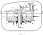
- the crankcase 10 comprises at least a first vertical projection 11a and at least a second vertical projection 11b for fixing the stator 40. Additionally, the crankcase 10 comprises a through hole for receiving the rotating shaft 20.
- Said rotating shaft 20 comprises at least one inner axial channel 21 for circulating lubricating oil, said inner axial channel 21 extending from the lower end to the upper end of said rotating shaft 20. Furthermore, the inner axial channel 21 is connected to at least one inner radial channel 22a, 22b for lubricating oil outlet, the inner axial channel 21 and the at least one inner radial channel 22a, 22b are fluidly connected to each other, so that the lubricating oil which enters the inner axial channel 21 exits through the inner radial channels 22a, 22b.
- the upper end of the rotating shaft 20 comprises a crankpin 23 associated with a connecting rod 24, the connecting rod 24 also being associated with a movable piston 25 within a compression cylinder 26.
- the rotor 30 comprises magnets 31 and is fixed to the rotating shaft 20 by means of a first fixing arrangement 32, said first fixing arrangement 32 may comprise any known fixation arrangement (by interference, welding, adhesive, screw, among others).
- the fixing arrangement 32 having the function of transmitting the movement of the rotor 30 to the rotating shaft 20.
- the rotor 30 is disposed above the stator 40.
- an axial bearing 50a is provided, used to limit the relative axial displacement between rotor 30 and stator 40 and, disposed between the lower region of the upper flange of the rotating shaft 20 and the upper region of the crankcase 10.
- This axial bearing 50a (which may comprise, for example, a plain sliding bearing, bearing or bushings of materials with a low friction coefficient), in addition to assisting the rotation of the rotating shaft 20, also prevents said rotating shaft 20 from undergoing axial displacements due to the magnetic attraction existing between the rotor 30 and the stator 40 when the motor is started.
- the stator 40 is above the rotor 30.
- an axial bearing 50b is provided, used to limit the relative axial displacement between rotor 30 and stator 40, and disposed between the rotor 30 and the stator 40 or between the rotor 30 and the annular structure 60.
- this configuration also provides a radial bearing which, integrated with the stator 40, is arranged around the rotating shaft 20.
- Said radial bearing can comprise any type of bearing already known, such as, for example, a hydrodynamic bearing (bearing with some type of lubricant supply between the minimum clearance of parallel surfaces and, in this case, axially aligned) or a hydrostatic bearing (bearing with forced supply of some type of lubricant injected under pressure between two parallel surfaces and, in this case, axially aligned), or bushings of some low-friction or self-lubricating material.
- the general structure of the stator 40 is used to enable the formation of a radial bearing for said rotating shaft 20, so that the rotating shaft 20 does not present problems of eccentricity and misalignment.
- the space formed between the annular structure 60 and the rotating axis 20 segment is adapted to retain a film of lubricating oil (from the inner radial channel 22a), forming a radial hydrodynamic bearing.
- the crankcase 10 can comprise an extended bearing hub 11c.
- the stator 40 is arranged above the rotor 30.
- an axial bearing 50c is provided between the rotor 30 and the extended bearing hub 11c.
- Figure 6 illustrates a second embodiment of the reciprocating compressor with axial flux motor according to the present invention.
- the reciprocating compressor comprises a crankcase 100, with a crankcase upper part 100a and a crankcase lower part 100b, a rotating shaft 200, with a rotating shaft first part 200a and a rotating shaft second part 200b, an oil pump C and an axial flux electric motor basically composed of a rotor 300 and a stator 400.
- the crankcase 100 comprises a first through hole 120a and a second through hole 120b for receiving the rotating shaft first part 200a and the rotating shaft second part 200b respectively.
- the rotating shaft 200 comprises an eccentric pin 230 disposed between the first part 200a and the second part 200b, the eccentric pin 230 being associated with a connecting rod 240, the connecting rod 240 also being associated with a movable piston 250 inside of a compression cylinder 260.
- the rotor 300 comprises magnets 310 and is fixed to the rotating shaft 200 by means of a first fixing arrangement 320
- said first fixing arrangement 320 can comprise any known fixation arrangement (welding, adhesive, screw, among others).
- the fixing arrangement 320 having the function of transmitting the movement of the rotor 300 to the rotating shaft 200.
- the stator 400 comprises electrical coils 410 and is fixed to the crankcase 100 by means of a second fixation arrangement 420, said fixation arrangement 420 comprising any known fixation arrangement (welding, adhesive, screw, among others).
- the fixing arrangement 420 having as function to keep the positioning of the stator 400, in relation to the crankcase 100, static.
- the space between the inner face of the first through hole 120a and the rotating shaft first part 200a receives a film of lubricating oil, forming a first hydrodynamic radial bearing 500a.
- the space between the inner face of the second through hole 120b and the rotating shaft second part 200b also receives a film of lubricating oil, forming a second hydrodynamic radial bearing 500b.
- the second embodiment of the present invention provides an axial bearing 600 to keep the axial spacing between rotor 300 and stator 400 stable. Therefore, the axial bearing 600 can be mounted between the eccentric pin 230 and the crankcase upper part 100a.
- the axial bearing 600 could also be mounted between the bearing hub 700 and the rotor 300.
- the second embodiment of the present invention also provides a radial bearing which, integrated with the stator 400, is arranged around the rotating shaft 200.
- Said radial bearing can comprise any type of bearing already known, such as, for example, a hydrodynamic bearing (bearing with some type of lubricant supply between the minimum clearance of parallel surfaces and, in this case, axially aligned) or a hydrostatic bearing (bearing with forced supply of some type of lubricant injected under pressure between two parallel surfaces and, in this case, axially aligned), or bushings of some low-friction or self-lubricating material.
- the general structure of the stator 400 is used to enable the formation of a radial bearing for said rotating shaft 200, so that the rotating shaft 200 does not present problems of eccentricity and misalignment.
- the radial bearing is defined by an annular structure 610, no part of the invention, integrated with the stator 400 and arranged around the rotating shaft 200. More particularly, the annular structure 610 is arranged around a segment of the rotating shaft 200 where the inner radial channel 222a is located.
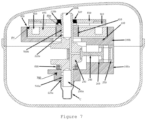
- Figure 7 illustrates an optional configuration of the second embodiment.
- the motor is above the cylinder.
- the present invention also provides configurations applicable to the first embodiment and to the second embodiment.
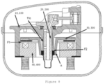
- the rotor 30, 300 and stator 40, 400 can be separated by a first axial clearance F1, and the rotating shaft 20, 200 and the crankcase 10, 100 can be separated by a second axial clearance F2.
- the first F1 and the second F2 clearances are adjustable using a bushing B arranged between the rotor 30, 300 and the rotating shaft 20, 200. Additionally, the first clearance F1 is formed by the displacement of rotor 30, 300 over the bushing B or by the displacement of stator 40, 400 over the crankcase 10, 100, while the second clearance F2 is formed by displacing the bushing B over the rotating axis 20, 200.
- the bushing B is an annular (sliding) part disposed between rotor 30, 300 and shaft 20, 200, allowing the second clearance F2 to be formed regardless of the formation of the first clearance F1.
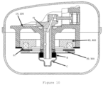
- an oil pump C of frustum-conical shape can be provided in the inner axial channel 21 of the rotating shaft 20, 200 or can be provided in the rotor 30, 300.
- the oil intake is optimized.
- the oil pump C also acts as an interface of physical contact between the rotor 30, 300 and the rotating shaft 20, 200, ensuring the fixation of these elements and transmitting the movement of the rotor 30, 300 to the rotating shaft 20, 200.
- the oil pump C can be fitted under interference on the rotating shaft 20, 200.
Landscapes
- Engineering & Computer Science (AREA)
- Mechanical Engineering (AREA)
- General Engineering & Computer Science (AREA)
- Compressor (AREA)
- Sliding-Contact Bearings (AREA)
- Shafts, Cranks, Connecting Bars, And Related Bearings (AREA)
- Connection Of Motors, Electrical Generators, Mechanical Devices, And The Like (AREA)
Claims (10)
- Hubkolbenverdichter, der Folgendes umfasst:ein Kurbelgehäuse (10),eine drehende Welle (20), die mindestens einen inneren axialen Kanal (21) umfasst, wobei der innere axiale Kanal (21) mit mindestens einem inneren radialen Kanal (22a, 22b) oder mit einem Kurbelzapfen (23) verbunden ist;der Kurbelzapfen (23) ist mit einer Verbindungsstange (24) verbunden, und die Verbindungsstange (24) ist mit einem beweglichen Kolben (25) in einem Verdichtungszylinder (26) verbunden; undeine Ölpumpe (C),einen Scheibenläufer-Elektromotor, der einen Rotor (30) mit Magneten (31) und einen Stator (40) mit Spulen (41) umfasst;wobei der Rotor (30) und der Stator (40) an der Welle (20) beziehungsweise am Kurbelgehäuse (10) über Lager oder Befestigungsanordnungen befestigt sind;wobei der Stator (40) sich zwischen dem Kurbelgehäuse (10) und dem Rotor (30) befindet und der Rotor (30) und der Stator (40) durch einen ersten axialen Zwischenraum (F1) getrennt sind;wobei die Welle (20) und das Kurbelgehäuse (10) durch einen zweiten, unteren axialen Zwischenraum (F2) getrennt sind;dadurch gekennzeichnet, dassder erste Zwischenraum (F1) und der zweite, untere axiale Zwischenraum (F2) durch Verschieben einer Buchse (B), die zwischen dem Rotor (30) und der drehenden Welle (20) angeordnet ist, verstellbar sind.
- Hubkolbenverdichter gemäß Anspruch 1, dadurch gekennzeichnet, dass der Rotor (30) an der drehenden Welle (20) über eine erste Befestigungsanordnung (32) befestigt ist.
- Hubkolbenverdichter gemäß Anspruch 1, dadurch gekennzeichnet, dass der Stator (40) am Kurbelgehäuse (10) über eine zweite Befestigungsanordnung (42) befestigt ist.
- Hubkolbenverdichter gemäß Anspruch 1, dadurch gekennzeichnet, dass er weiter ein Axiallager (50a) umfasst, angeordnet zwischen dem unteren Teil des oberen Flanschs der drehenden Welle (20) und dem oberen Teil des Kurbelgehäuses (10) .
- Hubkolbenverdichter gemäß Anspruch 1, dadurch gekennzeichnet, dass er weiter ein Axiallager (50b) umfasst, angeordnet zwischen der Buchse (B) des Rotors (30) und dem Stator (40).
- Hubkolbenverdichter gemäß Anspruch 1, dadurch gekennzeichnet, dass der Stator (40) weiter ein Radiallager umfasst, das um die drehende Welle (20) herum angeordnet ist, wobei das Radiallager durch eine Ringstruktur (60) bestimmt ist, welche, vom Stator (40) vorstehend, um ein Segment der drehenden Welle (20) herum angeordnet ist.
- Hubkolbenverdichter gemäß Anspruch 1, dadurch gekennzeichnet, dass er weiter eine verlängerte Lagernabe (11c) umfasst.
- Hubkolbenverdichter gemäß Anspruch 1, dadurch gekennzeichnet, dass er weiter ein Axiallager (50c) umfasst, das zwischen der Buchse (B) des Rotors (30) und der verlängerten Lagernabe (11c) angeordnet ist.
- Hubkolbenverdichter gemäß einem beliebigen der obigen Ansprüche, dadurch gekennzeichnet, dass der erste Zwischenraum (F1) durch Verschiebung des Rotors (30, 300) oder des Stators (40, 400) gebildet wird und der zweite Zwischenraum (F2b) durch Verschiebung der Buchse (B) gebildet wird.
- Hubkolbenverdichter gemäß einem beliebigen der obigen Ansprüche, dadurch gekennzeichnet, dass er eine Ölpumpe (C) mit Kegelstumpfform umfasst, angebracht im inneren axialen Kanal (21) der drehenden Welle (20, 200) oder im Rotor (30, 300).
Applications Claiming Priority (6)
| Application Number | Priority Date | Filing Date | Title |
|---|---|---|---|
| BR102019026313-0A BR102019026313A2 (pt) | 2019-12-11 | 2019-12-11 | Mecanismo de movimento alternativo provido de motor elétrico de fluxo axial |
| BR102019026308-3A BR102019026308A2 (pt) | 2019-12-11 | 2019-12-11 | compressor alternativo |
| BR102019026307-5A BR102019026307A2 (pt) | 2019-12-11 | 2019-12-11 | Compressor alternativo |
| BR102019026310-5A BR102019026310A2 (pt) | 2019-12-11 | 2019-12-11 | Compressor alternativo |
| BR102019026312-1A BR102019026312A2 (pt) | 2019-12-11 | 2019-12-11 | compressor alternativo |
| PCT/BR2020/050540 WO2021113943A1 (pt) | 2019-12-11 | 2020-12-11 | Compressor hermético alternativo com motor de fluxo axial |
Publications (3)
| Publication Number | Publication Date |
|---|---|
| EP4074968A1 EP4074968A1 (de) | 2022-10-19 |
| EP4074968C0 EP4074968C0 (de) | 2025-04-09 |
| EP4074968B1 true EP4074968B1 (de) | 2025-04-09 |
Family
ID=74346755
Family Applications (1)
| Application Number | Title | Priority Date | Filing Date |
|---|---|---|---|
| EP20848688.6A Active EP4074968B1 (de) | 2019-12-11 | 2020-12-11 | Hermetischer hubkolbenverdichter mit scheibenläufermotor |
Country Status (6)
| Country | Link |
|---|---|
| US (1) | US20230014696A1 (de) |
| EP (1) | EP4074968B1 (de) |
| JP (1) | JP7770317B2 (de) |
| CN (1) | CN115038868B (de) |
| BR (1) | BR112022011552A2 (de) |
| WO (1) | WO2021113943A1 (de) |
Families Citing this family (4)
| Publication number | Priority date | Publication date | Assignee | Title |
|---|---|---|---|---|
| US11936256B2 (en) | 2020-04-24 | 2024-03-19 | Jacobi Motors, Llc | Flux-mnemonic permanent magnet synchronous machine and magnetizing a flux-mnemonic permanent magnet synchronous machine |
| JP2023147824A (ja) * | 2022-03-30 | 2023-10-13 | セイコーエプソン株式会社 | 容積型機械、圧縮機、冷却装置及び電子機器 |
| US12558980B2 (en) | 2023-11-09 | 2026-02-24 | Jacobi Motors, Llc | Integrated variable flux memory motor charger |
| US12614998B2 (en) | 2024-03-04 | 2026-04-28 | Jacobi Motors, Llc | System for multi-variable flux memory motor configuration |
Family Cites Families (30)
| Publication number | Priority date | Publication date | Assignee | Title |
|---|---|---|---|---|
| US2715685A (en) * | 1953-03-23 | 1955-08-16 | Arthur E Brown | Dynamo-electric machine and reciprocable power unit therefor |
| US2797857A (en) * | 1953-07-16 | 1957-07-02 | Whirlpool Seeger Corp | Refrigerator compressor |
| DE1628157C3 (de) * | 1968-02-01 | 1973-10-11 | Danfoss A/S, Nordborg (Daenemark) | Einrichtung zum Kuhlen eines ge kapselten Motorverdichters, insbesondere Klemkaltemaschine |
| US3953751A (en) * | 1971-09-01 | 1976-04-27 | Papst Motoren Kg | Motor and mounting thereof |
| DE2711065C3 (de) * | 1977-03-14 | 1982-05-19 | Gesellschaft für Kernverfahrenstechnik mbH, 5170 Jülich | Radial gedämpftes Fanglager für überkritisch laufende Rotoren |
| AR222411A1 (es) * | 1979-09-21 | 1981-05-15 | Siegas Metallwarenfab | Motocompresor blindado para camaras frigorificas en especial |
| JPH0526915Y2 (de) * | 1986-10-29 | 1993-07-08 | ||
| DE59401553D1 (de) * | 1994-09-23 | 1997-02-20 | Siemens Ag | Axialspieleinstellung |
| KR100702369B1 (ko) * | 1999-08-09 | 2007-04-02 | 페름 모터 게엠베하 | 전기 축류장치와 그 제조방법 |
| US6484847B2 (en) * | 2000-11-30 | 2002-11-26 | Tecumseh Products Company | Lubricant pump with magnetic and centrifugal traps |
| US6765327B2 (en) * | 2002-03-27 | 2004-07-20 | The Timken Company | Integral driveline support and electric motor |
| US6922004B2 (en) * | 2002-04-05 | 2005-07-26 | The Timken Company | Axial flux motor assembly |
| KR20070054368A (ko) * | 2005-11-23 | 2007-05-29 | 주식회사 대우일렉트로닉스 | 로터의 위치 조절이 가능한 모터 |
| US7888904B2 (en) * | 2006-01-26 | 2011-02-15 | The Timken Company | Virtual moving air gap for an axial flux permanent magnet motor with dual stators |
| JP2007255244A (ja) * | 2006-03-22 | 2007-10-04 | Matsushita Electric Ind Co Ltd | 圧縮機 |
| WO2008014253A2 (en) * | 2006-07-24 | 2008-01-31 | The Timken Company | Electric motor with axially deformable rotor assembly |
| JP2008245504A (ja) * | 2007-10-24 | 2008-10-09 | Daikin Ind Ltd | 電機子コアの製造方法及び電機子コア |
| JP2011250537A (ja) * | 2010-05-25 | 2011-12-08 | Daikin Ind Ltd | アキシャルギャップ型モータ、流体機械、及び流体機械の組立て方法 |
| JP5460566B2 (ja) * | 2010-12-13 | 2014-04-02 | 株式会社日立製作所 | アキシャルギャップ型回転電機 |
| JP2013133758A (ja) * | 2011-12-27 | 2013-07-08 | Panasonic Corp | 密閉型圧縮機 |
| EP3090174A1 (de) * | 2013-11-29 | 2016-11-09 | Arçelik Anonim Sirketi | Hubkolbenverdichter mit reduzierten abmessungen und verbesserter form zur verwendung in einer kühlvorrichtung |
| CN203962324U (zh) * | 2014-07-01 | 2014-11-26 | 安徽美芝制冷设备有限公司 | 具有外转子式电机的压缩机 |
| CN105370537B (zh) * | 2014-08-28 | 2018-06-26 | 上海海立电器有限公司 | 一种压缩机及其复合机架的制造方法 |
| CN105332895B (zh) * | 2015-11-23 | 2018-01-02 | 珠海格力节能环保制冷技术研究中心有限公司 | 压缩机及其活塞组件 |
| CN106979140B (zh) * | 2016-01-19 | 2021-04-06 | 恩布拉科压缩机工业和制冷解决方案有限公司 | 包括润滑油泵送系统的变速冷却压缩机 |
| EP3270490B1 (de) * | 2016-07-13 | 2020-04-29 | Schwarzer Precision GmbH & Co. KG | Pumpe und verfahren zur verringerung oder beseitigung von störgeräuschen und/oder vibrationen bei pumpen |
| AT520633B1 (de) * | 2018-02-08 | 2019-06-15 | Miba Sinter Austria Gmbh | Pumpenanordnung, Axialflussmaschine und Kompressor |
| US10985639B2 (en) * | 2019-03-08 | 2021-04-20 | Regal Beloit America, Inc. | Axial flux electrical motor assembly and methods of assembling the same |
| DE102020126183A1 (de) * | 2020-10-07 | 2022-04-07 | Schaeffler Technologies AG & Co. KG | Axialflussmaschine |
| DE102020130125A1 (de) * | 2020-11-16 | 2022-05-19 | Aerolas Gmbh, Aerostatische Lager- Lasertechnik | Kraft- oder Arbeitsmaschine |
-
2020
- 2020-12-11 US US17/784,527 patent/US20230014696A1/en not_active Abandoned
- 2020-12-11 CN CN202080095325.6A patent/CN115038868B/zh active Active
- 2020-12-11 EP EP20848688.6A patent/EP4074968B1/de active Active
- 2020-12-11 BR BR112022011552A patent/BR112022011552A2/pt unknown
- 2020-12-11 WO PCT/BR2020/050540 patent/WO2021113943A1/pt not_active Ceased
- 2020-12-11 JP JP2022535643A patent/JP7770317B2/ja active Active
Also Published As
| Publication number | Publication date |
|---|---|
| CN115038868A (zh) | 2022-09-09 |
| JP2023510088A (ja) | 2023-03-13 |
| BR112022011552A2 (pt) | 2022-09-27 |
| JP7770317B2 (ja) | 2025-11-14 |
| WO2021113943A1 (pt) | 2021-06-17 |
| EP4074968C0 (de) | 2025-04-09 |
| CN115038868B (zh) | 2024-04-05 |
| US20230014696A1 (en) | 2023-01-19 |
| EP4074968A1 (de) | 2022-10-19 |
Similar Documents
| Publication | Publication Date | Title |
|---|---|---|
| EP4074968B1 (de) | Hermetischer hubkolbenverdichter mit scheibenläufermotor | |
| US6796120B2 (en) | Electrohydraulic actuator | |
| EP1065383B1 (de) | Dichtungslose integrierte Motorpumpe mit Seitenkanallaufrad | |
| AU2015272637B2 (en) | Piston pump and valve plate for piston pump | |
| US10876524B2 (en) | Linear compressor | |
| JP2008106941A (ja) | 油圧差動装置 | |
| EP2607696A1 (de) | Integrierte elektrohydraulische vorrichtung | |
| CA2772845A1 (en) | Piston engine having magnetic piston bearing | |
| US6135727A (en) | Detachably affixed counterweight and method of assembly | |
| EP2390511A1 (de) | Zusätzliche Abstützung für AMB-gestützte Rotoren mit Hilfe von Dauermagnetlagern | |
| CN104329232B (zh) | 一种永磁盘式电机驱动的一体式的径向柱塞泵 | |
| EP3759351B1 (de) | Vakuumpumpsystem mit einer vakuumpumpe und sein motor | |
| US6447267B1 (en) | Locomotive air compressor with motor supported by outside bearing | |
| JP4818378B2 (ja) | 電液一体型液圧装置 | |
| CN1303324C (zh) | 带有外部轴承所支承的电动机的机车空气压缩机 | |
| JPH0286976A (ja) | スクロール流体機械 | |
| JP3356460B2 (ja) | 密閉型圧縮機 | |
| US20120100021A1 (en) | Hermetic compressor | |
| JPH0291489A (ja) | スクロール流体機械 | |
| CN211950783U (zh) | 往复式压缩机 | |
| KR20000061153A (ko) | 피스톤식 압축기의 베어링구조 | |
| EP1247990A1 (de) | Kreiselpumpe mit selbstausgleichendem Axialantrieb | |
| CN211924399U (zh) | 往复式压缩机 | |
| CN211924400U (zh) | 往复式压缩机 | |
| JP7460923B2 (ja) | 回転式流体機械 |
Legal Events
| Date | Code | Title | Description |
|---|---|---|---|
| STAA | Information on the status of an ep patent application or granted ep patent |
Free format text: STATUS: UNKNOWN |
|
| STAA | Information on the status of an ep patent application or granted ep patent |
Free format text: STATUS: THE INTERNATIONAL PUBLICATION HAS BEEN MADE |
|
| PUAI | Public reference made under article 153(3) epc to a published international application that has entered the european phase |
Free format text: ORIGINAL CODE: 0009012 |
|
| STAA | Information on the status of an ep patent application or granted ep patent |
Free format text: STATUS: REQUEST FOR EXAMINATION WAS MADE |
|
| 17P | Request for examination filed |
Effective date: 20220613 |
|
| AK | Designated contracting states |
Kind code of ref document: A1 Designated state(s): AL AT BE BG CH CY CZ DE DK EE ES FI FR GB GR HR HU IE IS IT LI LT LU LV MC MK MT NL NO PL PT RO RS SE SI SK SM TR |
|
| DAV | Request for validation of the european patent (deleted) | ||
| DAX | Request for extension of the european patent (deleted) | ||
| STAA | Information on the status of an ep patent application or granted ep patent |
Free format text: STATUS: EXAMINATION IS IN PROGRESS |
|
| 17Q | First examination report despatched |
Effective date: 20240417 |
|
| GRAP | Despatch of communication of intention to grant a patent |
Free format text: ORIGINAL CODE: EPIDOSNIGR1 |
|
| STAA | Information on the status of an ep patent application or granted ep patent |
Free format text: STATUS: GRANT OF PATENT IS INTENDED |
|
| INTG | Intention to grant announced |
Effective date: 20241118 |
|
| GRAS | Grant fee paid |
Free format text: ORIGINAL CODE: EPIDOSNIGR3 |
|
| GRAA | (expected) grant |
Free format text: ORIGINAL CODE: 0009210 |
|
| STAA | Information on the status of an ep patent application or granted ep patent |
Free format text: STATUS: THE PATENT HAS BEEN GRANTED |
|
| AK | Designated contracting states |
Kind code of ref document: B1 Designated state(s): AL AT BE BG CH CY CZ DE DK EE ES FI FR GB GR HR HU IE IS IT LI LT LU LV MC MK MT NL NO PL PT RO RS SE SI SK SM TR |
|
| REG | Reference to a national code |
Ref country code: GB Ref legal event code: FG4D |
|
| REG | Reference to a national code |
Ref country code: CH Ref legal event code: EP |
|
| REG | Reference to a national code |
Ref country code: DE Ref legal event code: R096 Ref document number: 602020049263 Country of ref document: DE |
|
| REG | Reference to a national code |
Ref country code: IE Ref legal event code: FG4D |
|
| U01 | Request for unitary effect filed |
Effective date: 20250507 |
|
| U07 | Unitary effect registered |
Designated state(s): AT BE BG DE DK EE FI FR IT LT LU LV MT NL PT RO SE SI Effective date: 20250513 |
|
| REG | Reference to a national code |
Ref country code: SK Ref legal event code: T3 Ref document number: E 46568 Country of ref document: SK |
|
| PG25 | Lapsed in a contracting state [announced via postgrant information from national office to epo] |
Ref country code: ES Free format text: LAPSE BECAUSE OF FAILURE TO SUBMIT A TRANSLATION OF THE DESCRIPTION OR TO PAY THE FEE WITHIN THE PRESCRIBED TIME-LIMIT Effective date: 20250409 |
|
| PG25 | Lapsed in a contracting state [announced via postgrant information from national office to epo] |
Ref country code: NO Free format text: LAPSE BECAUSE OF FAILURE TO SUBMIT A TRANSLATION OF THE DESCRIPTION OR TO PAY THE FEE WITHIN THE PRESCRIBED TIME-LIMIT Effective date: 20250709 Ref country code: GR Free format text: LAPSE BECAUSE OF FAILURE TO SUBMIT A TRANSLATION OF THE DESCRIPTION OR TO PAY THE FEE WITHIN THE PRESCRIBED TIME-LIMIT Effective date: 20250710 |
|
| PG25 | Lapsed in a contracting state [announced via postgrant information from national office to epo] |
Ref country code: PL Free format text: LAPSE BECAUSE OF FAILURE TO SUBMIT A TRANSLATION OF THE DESCRIPTION OR TO PAY THE FEE WITHIN THE PRESCRIBED TIME-LIMIT Effective date: 20250409 |
|
| PG25 | Lapsed in a contracting state [announced via postgrant information from national office to epo] |
Ref country code: HR Free format text: LAPSE BECAUSE OF FAILURE TO SUBMIT A TRANSLATION OF THE DESCRIPTION OR TO PAY THE FEE WITHIN THE PRESCRIBED TIME-LIMIT Effective date: 20250409 |
|
| PG25 | Lapsed in a contracting state [announced via postgrant information from national office to epo] |
Ref country code: RS Free format text: LAPSE BECAUSE OF FAILURE TO SUBMIT A TRANSLATION OF THE DESCRIPTION OR TO PAY THE FEE WITHIN THE PRESCRIBED TIME-LIMIT Effective date: 20250709 |
|
| PG25 | Lapsed in a contracting state [announced via postgrant information from national office to epo] |
Ref country code: IS Free format text: LAPSE BECAUSE OF FAILURE TO SUBMIT A TRANSLATION OF THE DESCRIPTION OR TO PAY THE FEE WITHIN THE PRESCRIBED TIME-LIMIT Effective date: 20250809 |
|
| PG25 | Lapsed in a contracting state [announced via postgrant information from national office to epo] |
Ref country code: SM Free format text: LAPSE BECAUSE OF FAILURE TO SUBMIT A TRANSLATION OF THE DESCRIPTION OR TO PAY THE FEE WITHIN THE PRESCRIBED TIME-LIMIT Effective date: 20250409 |
|
| PGFP | Annual fee paid to national office [announced via postgrant information from national office to epo] |
Ref country code: TR Payment date: 20251114 Year of fee payment: 6 |
|
| PG25 | Lapsed in a contracting state [announced via postgrant information from national office to epo] |
Ref country code: CZ Free format text: LAPSE BECAUSE OF FAILURE TO SUBMIT A TRANSLATION OF THE DESCRIPTION OR TO PAY THE FEE WITHIN THE PRESCRIBED TIME-LIMIT Effective date: 20250409 |
|
| PGFP | Annual fee paid to national office [announced via postgrant information from national office to epo] |
Ref country code: SK Payment date: 20251202 Year of fee payment: 6 |
|
| U20 | Renewal fee for the european patent with unitary effect paid |
Year of fee payment: 6 Effective date: 20251230 |
|
| PLBE | No opposition filed within time limit |
Free format text: ORIGINAL CODE: 0009261 |
|
| STAA | Information on the status of an ep patent application or granted ep patent |
Free format text: STATUS: NO OPPOSITION FILED WITHIN TIME LIMIT |
|
| REG | Reference to a national code |
Ref country code: CH Ref legal event code: L10 Free format text: ST27 STATUS EVENT CODE: U-0-0-L10-L00 (AS PROVIDED BY THE NATIONAL OFFICE) Effective date: 20260218 |
|
| 26N | No opposition filed |
Effective date: 20260112 |