EP4074995A1 - LIAISON ARTICULAIRE ET PROCÉDÉ D'ACCOUPLEMENT MOBILE d'un PREMIER COMPOSANT À UN SECOND COMPOSANT - Google Patents
LIAISON ARTICULAIRE ET PROCÉDÉ D'ACCOUPLEMENT MOBILE d'un PREMIER COMPOSANT À UN SECOND COMPOSANT Download PDFInfo
- Publication number
- EP4074995A1 EP4074995A1 EP22165789.3A EP22165789A EP4074995A1 EP 4074995 A1 EP4074995 A1 EP 4074995A1 EP 22165789 A EP22165789 A EP 22165789A EP 4074995 A1 EP4074995 A1 EP 4074995A1
- Authority
- EP
- European Patent Office
- Prior art keywords
- connecting element
- area
- receiving element
- recess area
- transverse dimension
- Prior art date
- Legal status (The legal status is an assumption and is not a legal conclusion. Google has not performed a legal analysis and makes no representation as to the accuracy of the status listed.)
- Withdrawn
Links
- 230000008878 coupling Effects 0.000 title claims description 9
- 238000010168 coupling process Methods 0.000 title claims description 9
- 238000005859 coupling reaction Methods 0.000 title claims description 9
- 238000000034 method Methods 0.000 title claims description 7
- 239000011248 coating agent Substances 0.000 claims description 12
- 238000000576 coating method Methods 0.000 claims description 12
- 238000004519 manufacturing process Methods 0.000 claims description 7
- 230000003993 interaction Effects 0.000 claims description 5
- 238000003780 insertion Methods 0.000 claims description 4
- 230000037431 insertion Effects 0.000 claims description 4
- 238000006073 displacement reaction Methods 0.000 claims description 2
- 239000000463 material Substances 0.000 description 10
- 239000000725 suspension Substances 0.000 description 9
- 239000007769 metal material Substances 0.000 description 4
- 239000004033 plastic Substances 0.000 description 4
- 229920003023 plastic Polymers 0.000 description 4
- 230000008901 benefit Effects 0.000 description 3
- 238000005516 engineering process Methods 0.000 description 3
- 230000008569 process Effects 0.000 description 3
- XAGFODPZIPBFFR-UHFFFAOYSA-N aluminium Chemical compound [Al] XAGFODPZIPBFFR-UHFFFAOYSA-N 0.000 description 2
- 229910052782 aluminium Inorganic materials 0.000 description 2
- 230000008859 change Effects 0.000 description 2
- 238000010276 construction Methods 0.000 description 2
- 230000006870 function Effects 0.000 description 2
- 238000009434 installation Methods 0.000 description 2
- 230000007704 transition Effects 0.000 description 2
- 229920002430 Fibre-reinforced plastic Polymers 0.000 description 1
- 229910000831 Steel Inorganic materials 0.000 description 1
- 239000004809 Teflon Substances 0.000 description 1
- 229920006362 Teflon® Polymers 0.000 description 1
- RTAQQCXQSZGOHL-UHFFFAOYSA-N Titanium Chemical compound [Ti] RTAQQCXQSZGOHL-UHFFFAOYSA-N 0.000 description 1
- 238000005299 abrasion Methods 0.000 description 1
- 238000005260 corrosion Methods 0.000 description 1
- 230000007797 corrosion Effects 0.000 description 1
- 238000013016 damping Methods 0.000 description 1
- 230000001419 dependent effect Effects 0.000 description 1
- 239000011151 fibre-reinforced plastic Substances 0.000 description 1
- 238000011089 mechanical engineering Methods 0.000 description 1
- 230000007246 mechanism Effects 0.000 description 1
- 230000009993 protective function Effects 0.000 description 1
- 230000035939 shock Effects 0.000 description 1
- 239000004447 silicone coating Substances 0.000 description 1
- 239000010959 steel Substances 0.000 description 1
- 239000012815 thermoplastic material Substances 0.000 description 1
- 229910052719 titanium Inorganic materials 0.000 description 1
- 239000010936 titanium Substances 0.000 description 1
- 239000013598 vector Substances 0.000 description 1
- 230000000007 visual effect Effects 0.000 description 1
Images



Classifications
-
- F—MECHANICAL ENGINEERING; LIGHTING; HEATING; WEAPONS; BLASTING
- F16—ENGINEERING ELEMENTS AND UNITS; GENERAL MEASURES FOR PRODUCING AND MAINTAINING EFFECTIVE FUNCTIONING OF MACHINES OR INSTALLATIONS; THERMAL INSULATION IN GENERAL
- F16C—SHAFTS; FLEXIBLE SHAFTS; ELEMENTS OR CRANKSHAFT MECHANISMS; ROTARY BODIES OTHER THAN GEARING ELEMENTS; BEARINGS
- F16C11/00—Pivots; Pivotal connections
- F16C11/04—Pivotal connections
- F16C11/06—Ball-joints; Other joints having more than one degree of angular freedom, i.e. universal joints
- F16C11/0685—Manufacture of ball-joints and parts thereof, e.g. assembly of ball-joints
-
- F—MECHANICAL ENGINEERING; LIGHTING; HEATING; WEAPONS; BLASTING
- F16—ENGINEERING ELEMENTS AND UNITS; GENERAL MEASURES FOR PRODUCING AND MAINTAINING EFFECTIVE FUNCTIONING OF MACHINES OR INSTALLATIONS; THERMAL INSULATION IN GENERAL
- F16C—SHAFTS; FLEXIBLE SHAFTS; ELEMENTS OR CRANKSHAFT MECHANISMS; ROTARY BODIES OTHER THAN GEARING ELEMENTS; BEARINGS
- F16C11/00—Pivots; Pivotal connections
- F16C11/04—Pivotal connections
- F16C11/06—Ball-joints; Other joints having more than one degree of angular freedom, i.e. universal joints
- F16C11/0604—Construction of the male part
-
- F—MECHANICAL ENGINEERING; LIGHTING; HEATING; WEAPONS; BLASTING
- F16—ENGINEERING ELEMENTS AND UNITS; GENERAL MEASURES FOR PRODUCING AND MAINTAINING EFFECTIVE FUNCTIONING OF MACHINES OR INSTALLATIONS; THERMAL INSULATION IN GENERAL
- F16C—SHAFTS; FLEXIBLE SHAFTS; ELEMENTS OR CRANKSHAFT MECHANISMS; ROTARY BODIES OTHER THAN GEARING ELEMENTS; BEARINGS
- F16C11/00—Pivots; Pivotal connections
- F16C11/04—Pivotal connections
- F16C11/06—Ball-joints; Other joints having more than one degree of angular freedom, i.e. universal joints
- F16C11/0619—Ball-joints; Other joints having more than one degree of angular freedom, i.e. universal joints the female part comprising a blind socket receiving the male part
- F16C11/0623—Construction or details of the socket member
-
- B—PERFORMING OPERATIONS; TRANSPORTING
- B64—AIRCRAFT; AVIATION; COSMONAUTICS
- B64D—EQUIPMENT FOR FITTING IN OR TO AIRCRAFT; FLIGHT SUITS; PARACHUTES; ARRANGEMENT OR MOUNTING OF POWER PLANTS OR PROPULSION TRANSMISSIONS IN AIRCRAFT
- B64D11/00—Passenger or crew accommodation; Flight-deck installations not otherwise provided for
- B64D11/003—Stowage devices for passengers' personal luggage
-
- F—MECHANICAL ENGINEERING; LIGHTING; HEATING; WEAPONS; BLASTING
- F16—ENGINEERING ELEMENTS AND UNITS; GENERAL MEASURES FOR PRODUCING AND MAINTAINING EFFECTIVE FUNCTIONING OF MACHINES OR INSTALLATIONS; THERMAL INSULATION IN GENERAL
- F16C—SHAFTS; FLEXIBLE SHAFTS; ELEMENTS OR CRANKSHAFT MECHANISMS; ROTARY BODIES OTHER THAN GEARING ELEMENTS; BEARINGS
- F16C2226/00—Joining parts; Fastening; Assembling or mounting parts
- F16C2226/50—Positive connections
- F16C2226/70—Positive connections with complementary interlocking parts
- F16C2226/72—Positive connections with complementary interlocking parts with bayonet joints, i.e. parts are rotated to create positive interlock
Definitions
- the present invention relates to the making of articulated, moveable couplings between components.
- the present invention relates to an articulation for movably coupling a first component to a second component and an aircraft with such an articulation and a method for producing a movably attachment of a first component to a second component.
- components to be connected are often coupled to one another by means of movable or flexible connections.
- fixtures or secondary structures are securely fastened inside the vehicle or aircraft in order to ensure certain minimum requirements for operational safety.
- loads acting on the vehicle installations are introduced by means of a suspension from the installations into the primary structure of the vehicle or aircraft.
- the structural integrity can also require that some of such components are movably connected to one another in order to meet specific requirements for the respectively desired introduction of force into the primary structure.
- articulated connections should also be easy to produce, that is, they should be easy to assemble. This can be particularly relevant if the view of the assembly point for the articulated joint is blocked by adjacent components or the assembly point is difficult to access.
- DE 10 2017 131 150 A1 and U.S. 2019/0 193 872 A1 describe a modular system for installing modules on a body structure of a vehicle.
- the system comprises several modules with holders arranged on them for fastening to a fuselage structure, several assembly frames that can be moved on a floor level and at least one connecting element which is at least partially flexible and extends over all modules and couples them to one another when installed on the fuselage structure.
- an articulation for movably coupling a first component to a second component includes a receiving element and a connecting element. It can be provided that the first component on the receiving element and the second component on the Connecting element is attached.
- the receiving member has a recessed portion including an opening recessed portion on a surface of the receiving member and an inner recessed portion, the inner recessed portion being accessible along a recessed axis via the opening recessed portion.
- the interior cutout area has a first transverse dimension that is greater than a first transverse dimension of the opening cutout area.
- the fastener has a neck portion and a first end portion having a curved surface contour, the neck portion and first end portion being disposed along a fastener axis.
- the first end portion has a first transverse dimension that is greater than a first transverse dimension of the neck portion.
- the connecting element can be inserted at least partially into the cut-out area of the receiving element when the connecting element and the receiving element are in a predetermined first orientation relative to one another.
- the connecting element can be converted into a locking state in the recess area of the receiving element, in which the connecting element and the receiving element are in a predetermined second orientation relative to one another, so that the connecting element is prevented from moving out of the recess area. Starting from the locked state, the connecting element can then be rotated relative to the receiving element in order to thus provide the movable coupling between the first component and the second component.
- the articulated connection With the articulated connection according to the invention, a simply constructed and therefore easy to manufacture and cost-effective articulated connection is provided, which enables components of any design to be movably attached to one another.
- a significant advantage of the articulated connection is its self-centering property during assembly, that is to say when the connecting element is inserted into the recess area of the receiving element.
- the first end area of the connecting element which faces the opening recess area of the receiving element during assembly, has a curved surface contour which is designed in such a way that the first end area and thus the connecting element move when they come into contact with an opening boundary of the Opening recess area self-aligns or self-centered.
- This self-centering simplifies the insertion of the connecting element into the recess area and the subsequent turning of the connecting element into the locking state, so that assembly is also easily possible without visual contact with the articulated connection.
- the assembly can be carried out in such a way that the first end area is inserted or pushed into the recess area in that the connecting element rotates automatically in relation to the receiving element into the correct assembly alignment as soon as the curved surface contour of the first end area of the connecting element meets the opening recess area and thus the surface of the receiving element comes into contact.
- the first end portion of the connector can be slid fully into the socket portion of the socket. Once there, the articulation is brought into the locking state by rotating the elongate connecting element about its axis, ie about the axis of the connecting element.
- the locking state prevents the connecting element from being moved or pulled out of the recess area of the receiving element, but at least a limited rotational movement of the connecting element relative to the receiving element remains possible in principle, in order to enable the movable coupling as described above. Consequently, due to the flexible coupling possibility of different components to be connected, the articulated connection provides suitable tolerance compensation, which plays a major role in particular for the structural integrity.
- the articulated connection avoids the occurrence of high torques within the connection, while the advantageous properties with regard to tolerance compensation and self-centering or assembly simplicity are nevertheless achieved.
- the receiving member may enclose most or all of the first end portion when the first end portion is inserted into the socket portion of the receiving member and the first end portion is within the socket portion. In this way, a quasi-closed profile of the articulated connection can be provided.
- the fact that the joint connection according to the invention requires comparatively few individual parts not only simplifies assembly but also leads to a lighter overall design of the joint connection, which is particularly important in lightweight construction, for example in aircraft technology.
- the connecting element and/or the receiving element can have a metallic material or a plastic material, for example. Fiber-reinforced plastics also come into consideration.
- metallic material the connecting element and/or the receiving element can be made of aluminum, in particular surface-coated aluminum, titanium or steel.
- the connecting element and/or the receiving element can have thermoplastic material, for example, which can also be fiber-reinforced.
- the receiving element can be attached to the first component or integrated into it.
- the connecting element can be attached to the second component or integrated into it.
- the first component can be movably coupled to the second component via the articulated joint, so that the first component is rotatable relative to the second component, the rotation being enabled in the locked state of the articulated joint, i.e. when the connecting element and the receiving element are in any of several predetermined second orientations to each other, which in any case differs from the first orientation.
- the connecting element or the first end area of the connecting element can only be inserted into the inner recess area of the receiving element or moved out again when the connecting element and the receiving element are essentially or exactly in the predetermined first orientation to one another. In any other Orientation deviating from the first orientation can be prevented from being inserted or moved out.
- the receiving element can be rotated at least partially around the first end region of the connecting element in the locked state.
- the locking state can thus describe a state in which, although the first end region is prevented from moving out of the inner recess region of the receiving element and is thus locked, a rotational movement of the connecting element with respect to the receiving element can remain possible.
- the locked state can prevent a relative translational movement between the connecting element and the receiving element, but allow a rotational movement of both parts to one another.
- the connecting element can be introduced into the cut-out area by displacing the connecting element along the cut-out axis.
- the opening cutout area of the receiving element can be designed such that the first end area of the connecting element fits through the opening cutout area in exactly one orientation (first orientation) and can be inserted into the cutout area in this orientation.
- first orientation first orientation
- the connecting element is pushed into the cut-out area in particular along the connecting element axis and/or the cut-out axis.
- the insertion can be made possible when the axis of the connecting element and the axis of the recess lie on top of one another, but are at least aligned in parallel.
- the connecting element is in the recess area of the receiving element by a rotary movement about the axis of the connecting element the locked state can be converted in order to thus movably couple the first component to the second component.
- the connecting element can be brought into the second orientation, which differs from the first orientation, relative to the receiving element, a rotation about the axis of the connecting element takes place, which leads to the locking state explained above.
- this rotation can only take place when the first end area of the connecting element is located completely within the inner recess area of the receiving element. If, for example, the first end area of the connecting element is located in the opening cutout area of the receiving element, then rotation would be prevented since the first end area in particular is larger in its first transverse extent than the opening cutout area in its first transverse dimension.
- the neck area of the connecting element has a smaller transverse extent in the radial direction than the opening recess area, the neck area can, on the other hand, be rotated completely within the opening recess area. This will also become clearer in more detail in the description of the figures.
- the connecting element is blocked from moving out of the cutout area in the locked state by interaction of the first end area with the opening cutout area, in particular with an opening delimitation of the opening cutout area.
- first transverse extent of the end region is greater than the first transverse dimension of the opening cutout area, so that the first end region does not fit through the opening defined by the opening cutout area when the connecting element is in a different from the first orientation to the receiving element, second orientation is located.
- Said interaction can be characterized by abutting or contact between the first end area and a material projection of the opening delimitation that forms the opening recess area.
- the connecting element and the receiving element are in the predetermined first orientation with respect to one another when the first transverse dimension of the opening relief region is substantially or exactly perpendicular to the first transverse extent of the first end region.
- the first end area fits through the opening recess area solely in this first orientation due to its shape and/or size.
- the connecting element and the receiving element are in the predetermined second orientation with respect to one another when the first transverse dimension of the opening relief area is not oriented perpendicularly to the first transverse extent of the first end area.
- the second orientation may be any of a variety of different orientations, so long as the first transverse dimension of the opening relief portion is not oriented perpendicular to the first transverse extent of the first end portion.
- there can be a plurality of second orientations namely all those orientations in which the first transverse dimension of the opening cutout area is not perpendicular to the first transverse extent of the first end area, wherein in all second orientations the first end area is not defined by the Opening recess area passes through and thus moving out of the first end portion is blocked from the inner recess area.
- the inner recess area at least partially has a spherical segment surface and the first end area also at least partially has a spherical segment surface.
- a type of ball joint connection can thus be provided, so that a rotational movement in the locked state results in a rotation of the connecting element is possible with respect to the receiving element.
- the spherical segment surface of the first end portion may define a spherical shape that extends around the first end portion except for the point of attachment of the first end portion to the neck portion of the fastener.
- the first end area can thus form a type of joint ball and the inner recess area can form the corresponding joint socket. This offers the advantage of a comparatively large contact area within the joint connection, which also increases the loads that can be transmitted.
- the socket area has an inner surface that is provided with a coating.
- the first end area has an outer surface that is provided with a coating.
- a damping function for shock loads or vibrations can be provided, which improves both the mechanical and the acoustic properties when the joint connection is integrated into a system.
- a mechanical protective function can be provided, for example by the coating being a wear-resistant coating which reduces abrasion during relative movement of the first end region within the inner recess region.
- the coating can reduce friction between these two components.
- the coating can be a Teflon coating or a silicone coating.
- a corrosion-resistant and impact-resistant articulated connection can be provided by the coating and the materials used for the connecting element and the receiving element.
- an aircraft with an articulation as described above and below is provided.
- the articulation may be part of a truss structure or suspension within the aircraft.
- the articulated connection according to the invention can also be used in other areas of application, for example in vehicle construction, in shipbuilding or in transport in general.
- the articulated joint can be used to transport loads when a moveable attachment of the load to the respective means of transport is required.
- the articulated connection can be used when transporting containers by means of crane systems, etc.
- the use of the articulated connection in stationary facilities, for example in buildings, is also possible.
- a method for producing a movable attachment of a first component to a second component is specified.
- a receiving element is provided with a cut-out area, which comprises an opening cut-out area on a surface of the receiving element and an inner cut-out area, the inner cut-out area being accessible along a cut-out axis via the opening cut-out area.
- the interior cutout area has a first transverse dimension that is greater than a first transverse dimension of the opening cutout area.
- a connecting element is provided with a neck area and a first end area, the neck area and the first end area being arranged along a connecting element axis.
- the first end portion has a first transverse dimension that is greater than a first transverse dimension of the neck portion.
- the connecting element is displaced along the cut-out axis in the direction of the cut-out area, so that the connecting element centers itself relative to the receiving element by interacting with a boundary surface of the opening cut-out area.
- the connecting element is inserted or pushed into the cut-out area of the receiving element when the connecting element and the receiving element are in a predetermined first orientation relative to one another, with the connecting element axis and the cut-out axis in particular lying on top of one another or lying parallel to one another.
- the connecting element is transferred within the recess area of the receiving element into a locking state in which the connecting element and the receiving element are in a predetermined second orientation relative to one another, so that the connecting element is moved out is prevented from the recess area.
- FIG. 1 shows a plan view of a receiving element 20 for an articulated connection, in particular for those in FIGS Figures 7 to 10 described articulation 10.
- the in the Figures 1, 2 and 7 to 10 The representations of the receiving element 20 shown each represent a sectional view of the receiving element 20, the section of these sectional views possibly running through a point of the largest diameter of the recess region 21.
- the receiving element 20 has a recess area 21 which is divided into an opening recess area 22 in the area of a surface 23 of the receiving element 20 and an inner recess area 24 in a central area of the receiving element 20 .
- the inner cutout area 24 is accessible along a cutout axis 25 via the opening cutout area 22 .
- the receiving element 20 forms a material body 27 which, for example, comprises a metallic material or a plastic material, the material body 27 defining the recess area 21 in the interior of the receiving element 20 .
- the inner recess area 24 has at least partially an inner surface in the shape of a segment of a sphere, which here is in the form of a segment of a hemisphere.
- FIG 2 shows a side view of the receiving element 20 of FIG 1 .
- a comparison of Figures 1 and 2 ie the plan view and the side view of the receiving element 20, makes it clear that the receiving element 20 has different cross sections in the two views.
- the two views of Figures 1 and 2 are perpendicular to each other in the present case.
- the inner recess area 24 has a first transverse dimension A 1 that is greater than a first transverse dimension B 1 of the opening recess area 22. That is, in the side view, the cross section tapers at least partially, starting from the inner recess area 24 towards the opening recess area 22.
- the taper is in the form of a curved contour.
- the internal recess area 24 thus has a second transverse dimension A2 which is substantially equal or exactly equal to a second transverse dimension B2 of the Opening recess area 22 is.
- the receiving element 20 comprises an undercut in the first transverse dimension direction (cf. 2 ), whereby an undercut in the second transverse dimension direction is not provided (cf. 1 ).
- FIG. 1 and 2 For a better understanding shows 3 a front view of the receiving element 20 of FIG Figures 1 and 2 .
- the undercut in the first transverse dimension direction can be seen, the undercut resulting from the fact that the first transverse dimension A 1 of the inner recess area 24 is larger than the first transverse dimension B 1 of the opening recess area 22.
- the second transverse dimension A 2 and B 2 of the inner recess area 24 or the opening recess area 22 is the same size, so that there is no undercut in the second transverse dimension direction.
- connection element 30 has an elongate or rod-shaped neck region 31 and a first end region 32 with a curved surface contour 33.
- the curved surface contour 33 has the shape of a spherical surface which extends at least partially around the first end area 32 , apart from a connection point which connects the first end area 32 to the neck area 31 .
- the neck portion 31 and the first end portion 32 are arranged along a connector axis 35 . This means that the first end area 32 and the neck area 31 are connected to one another along the connecting element axis 35 .
- the connecting element 30 forms a material body 37 which, for example, comprises a metallic material or a plastic material, the material body 37 defining the first end region 32 and the neck region 31 of the connecting element 30 .
- figure 5 shows a side view of the connecting element 30 of FIG 4 .
- a comparison of Figures 4 and 5 ie the plan view and the side view of the connecting element 30, makes it clear that the connecting element 30 has different cross sections in the two views.
- the two views of Figures 4 and 5 are perpendicular to each other in the present case.
- the first End region 32 has a first transverse extent C 1 which is greater than a first transverse extent D 1 of neck region 31.
- the taper is in the form of a curved contour.
- the curved contour here has the shape of a circular arc.
- the first end region 32 thus has a second transverse dimension C 2 which is substantially equal or exactly equal to a second transverse dimension D2 of the neck region 31 .
- figure 5 also shows that the curved surface contour 33 of the first end area 32 forms a termination of the connecting element 30, i.e. faces away from the neck area 31.
- This curved surface contour 33 at the end of the connecting element offers advantages for a self-centering function when inserting the connecting element 30 into the receiving element 20, as shown in FIGS Figures 7 and 8 shown.
- FIG 6 still shows the front view of the connecting element 30 of FIG Figures 4 and 5 .
- the lateral ends (relative to the first transverse direction of extension) of the first end region 32 also have a curved shape.
- the respective second transverse dimensions C 2 and D 2 of the first end region 32 and of the neck region 31 are also shown, in which case in FIG 6 shown view of the neck area 31 is completely covered by the first end area 32.
- FIG. 7 shows the connecting element 30 of FIG Figures 4 to 6 and the receiving element 20 of Figures 1 to 3 , wherein both parts 20, 30 are shown in a disassembled state.
- the connecting element 30 and the receiving element 20 are in a predetermined first orientation 40 to one another. That is, both parts 20, 30 are arranged in a specific orientation relative to one another such that the first transverse dimension B 1 of the opening recess area 22 is perpendicular to the first transverse dimension C 1 of the first end portion 32 is located.
- the first transverse extent C 1 shows in 7 perpendicular to the plane of the drawing.
- the second transverse dimension C 2 of the first end region 32 is slightly smaller than the first transverse dimension B 1 of the opening recess region 22, so that the connecting element 30, after being brought into the first orientation 40, is then introduced into the recess region 21 of the receiving element 20 can be. If the first end region 32 strikes the opening recess region or the surface 23 of the receiving element 20 in an orientation that deviates from the first orientation 40, the connecting element 30 cannot be inserted directly into the recess region 21, although the connecting element 30 can automatically move into center the first orientation 40 with respect to the receiving member 20 . This is achieved by the curved surface 33 of the first end area 32 (cf. figure 5 ) and the curved lateral surfaces of the first end region 32 (cf. 6 ) allows, since these curved surfaces can slide on contact with the opening boundary of the opening recess area 22, so that the connecting element 30 rotates relative to the receiving element 20 and is thus automatically centered.
- the second transverse dimensions C 2 and D 2 of the first end portion 32 and the neck portion 31 are parallel to the first transverse dimensions A 1 and B 1 of the inner relief portion 24 and the opening relief portion 22, respectively.
- the connecting element 30 can be inserted into the recess area 21, which in 8 indicated by arrow 50.
- the connecting element 30 is thus introduced into the recess region 21 by sliding 50 the connecting element 30 in the direction of the arrow along the recess axis 25 .
- the connecting element axis 35 and the recess axis 25 lie one on top of the other or are in any case arranged parallel to one another.
- FIG. 8 shows the connecting element 30 and the receiving element 20 during an assembly process. It can be seen that the connecting element 30 has been pushed into the recess area 21 of the receiving element 20 almost as far as it will go. In this assembly state, the first end region 32 is located completely in the inner recess region 24 of the receiving element 20. However, the receiving element 20 and the connecting element 30 are still in the first orientation 40 to one another, so that the connecting element 30 can still be moved out of the recess region 21.
- the articulated connection comprises the connecting element 30 and the receiving element 20 in an assembled state, which is also referred to as the locking state 13 .
- the connecting element 30 was thus transferred to the locking state 13 within the recess area 21 of the receiving element 20, in which the connecting element 30 and the receiving element 20 are in a predetermined second orientation 60 to one another, so that the connecting element 30 is prevented from moving out of the recess area 21 .
- the connecting element 30 was transferred to the locking state 13 in particular within the cutout area 21 of the receiving element 20 by a rotary movement 51 (represented by a double arrow) about the connecting element axis 35 .
- This locking state 13 can be given by several different second orientations 60 of the connecting element 30 relative to the receiving element 20 as long as the first transverse dimension B 1 of the opening recess region 22 is not perpendicular to the first transverse extent C 1 of the first end region 32, with the perpendicular state in the Figures 7 and 8 is shown.
- there can be a plurality of second orientations 60 namely all those orientations 60 in which the first transverse dimension B 1 of the opening recess region 24 is not perpendicular to the first transverse extent C 1 of the first end region 32, with the first end region 32 due to its shape and/or size, does not fit through the opening recess area 22 and thus blocks the first end region 32 from moving out of the inner recess area 24 is.
- This blocked or locked state 13 is in 9 shown, wherein in the specifically illustrated case the connecting element 30 was rotated through 90° relative to the receiving element 20 during the rotary movement 51 in order to lock both parts 20, 30 together, so that here the first transverse dimensions A 1 , B 1 of the inner recess area 22 or . _ Moving out of the connecting element 30 from the recess area 21 is blocked in the locking state 13 by the interaction of the first end area 32 with the opening delimitation in the opening recess area 22 .
- the receiving element 20 is always movably mounted relative to the connecting element 30, so that the connecting element axis 35 and the recess axis 25 can enclose a non-zero variable angle, i.e. do not have to be parallel to one another .
- articulation 10 provides a movable coupling of two components.
- the inner recess area 24 can have an inner surface 26 ( 7 ) which is provided with a coating.
- the first end portion 32 may have an outer surface 34 ( figure 5 ) which is provided with a coating.
- the transverse dimensions A 1 , A 2 , B 1 , B 2 and transverse extents C 1 , C 2 , D 1 , D 2 illustrated in the figures can each indicate directional vectors.
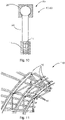
- 10 shows the in 9 manufactured joint connection 10 with a locking unit 14.
- 10 shows in particular a system with the joint connection 10 and the locking unit 14.
- the locking unit 14 has a mechanism 15 which causes the connecting element 30 to rotate relative to the receiving element 20 and can lock a specific rotational position in the locking state 13, so that the
- the connecting element 30 is first pushed into the receiving element 20 and then brought into the locked state, ie the locking state 13, by the rotation of the connecting element 30.
- FIG. 11 12 shows a suspension 110 or truss structure 110 having a plurality of articulations 10 disposed within the suspension 110 to provide moveable, i.e. flexible, load transfer points within the suspension 110.
- the suspension 110 can be part of a vehicle or aircraft.
- the suspension 110 can be coupled via the articulated connections 10 to a primary structure, such as frames and stringers of the vehicle or aircraft.
- the means of transport 120 can be a drone, a helicopter or the like.
- four receiving elements 20 are shown on the means of transport 120, which includes the first component 11 in the form of a fastening unit.
- These four female members 20 each face four corresponding connector members 30 with which they can be engaged by displacement 50 to form four articulations 10 so that the second component 12, which is in unit load form, via the articulations made therewith 10 can be movably attached to the first component 11 of the transport means 120 .
- FIG. 1 shows an aircraft 100 with an articulation 10.
- the articulation 10 may be part of a suspension 110 of the aircraft.
- the articulated connections 10 can be connected to a primary structure of the aircraft, such as frames and stringers.
- a receiving element 20 is provided with a recess area 21, which has an opening recess area 22 on a surface 23 of the receiving element 20 and comprises an inner recess area 24, the inner recess area 24 being accessible along a recess axis 25 via the opening recess area 22 and the inner recess area 24 having a first transverse dimension A 1 which is greater than a first transverse dimension B 1 of the opening recess area 22.
- a second step S2 takes place providing a fastener 30 having a neck portion 31 and a first end portion 32, the neck portion 31 and the first end portion 32 being disposed along a fastener axis 35, the first end portion 32 having a first transverse dimension C 1 a
- the connecting element 30 is displaced 50 along the cut-out axis 25 in the direction of the cut-out area 21, so that the connecting element 30 opposes itself by interacting with the opening cut-out area 22 centered on the receiving element 2 itself.
- the connecting element 30 is inserted into the recess area 21 of the receiving element 20 when the connecting element 30 and the receiving element 20 are in a predetermined first orientation 40 to one another.
- step S5 the connecting element 30 in the recess area 21 of the receiving element 20 is transferred into a locking state 13, in which the connecting element 30 and the receiving element 20 are in a predetermined second orientation 60 to one another, so that the connecting element 30 can be moved out the recess area 21 is prevented.
Landscapes
- Engineering & Computer Science (AREA)
- General Engineering & Computer Science (AREA)
- Mechanical Engineering (AREA)
- Connection Of Plates (AREA)
- Toys (AREA)
Applications Claiming Priority (1)
| Application Number | Priority Date | Filing Date | Title |
|---|---|---|---|
| DE102021109529.8A DE102021109529A1 (de) | 2021-04-15 | 2021-04-15 | Gelenkverbindung und Verfahren zum beweglichen Koppeln einer ersten Komponente an einer zweiten Komponente |
Publications (1)
| Publication Number | Publication Date |
|---|---|
| EP4074995A1 true EP4074995A1 (fr) | 2022-10-19 |
Family
ID=81074149
Family Applications (1)
| Application Number | Title | Priority Date | Filing Date |
|---|---|---|---|
| EP22165789.3A Withdrawn EP4074995A1 (fr) | 2021-04-15 | 2022-03-31 | LIAISON ARTICULAIRE ET PROCÉDÉ D'ACCOUPLEMENT MOBILE d'un PREMIER COMPOSANT À UN SECOND COMPOSANT |
Country Status (2)
| Country | Link |
|---|---|
| EP (1) | EP4074995A1 (fr) |
| DE (1) | DE102021109529A1 (fr) |
Cited By (1)
| Publication number | Priority date | Publication date | Assignee | Title |
|---|---|---|---|---|
| EP4764237A1 (fr) * | 2024-12-20 | 2026-06-24 | Stabilus GmbH | Joint articulé entre une tige de couplage et un chariot d'un guidage linéaire et procédé de montage |
Citations (3)
| Publication number | Priority date | Publication date | Assignee | Title |
|---|---|---|---|---|
| US20150251511A1 (en) * | 2014-03-04 | 2015-09-10 | Federal-Mogul Motorparts Corporation | Ball joint assembly for a control arm |
| DE102017131150A1 (de) | 2017-12-22 | 2019-06-27 | Airbus Operations Gmbh | Modulsystem zur Installation von Modulen an einer Rumpfstruktur eines Fahrzeugs |
| FR3100504A1 (fr) * | 2019-09-09 | 2021-03-12 | Valeo Systemes D'essuyage | Maneton, boîte à rotule et système de tringlerie d’actionnement d’essuie-glaces correspondant et son procédé d’assemblage |
Family Cites Families (5)
| Publication number | Priority date | Publication date | Assignee | Title |
|---|---|---|---|---|
| US3462179A (en) | 1967-10-16 | 1969-08-19 | Donald L Hinkle | Safety coupling or connector |
| US3661411A (en) | 1970-11-16 | 1972-05-09 | Jewell Mfg Co | Joint construction |
| US4619549A (en) | 1984-11-13 | 1986-10-28 | Builders Equipment And Tool Manufacturing Company | Scaffolding connection apparatus and method |
| DE102017219150A1 (de) | 2017-10-25 | 2019-04-25 | Airbus Operations Gmbh | Drehgelenk und Befestigungsanordnung |
| DE102018220223A1 (de) | 2018-11-26 | 2020-05-28 | Ford Global Technologies, Llc | Lagereinheit für ein Kugelgelenk, Kugelgelenk und Kraftfahrzeug |
-
2021
- 2021-04-15 DE DE102021109529.8A patent/DE102021109529A1/de active Pending
-
2022
- 2022-03-31 EP EP22165789.3A patent/EP4074995A1/fr not_active Withdrawn
Patent Citations (4)
| Publication number | Priority date | Publication date | Assignee | Title |
|---|---|---|---|---|
| US20150251511A1 (en) * | 2014-03-04 | 2015-09-10 | Federal-Mogul Motorparts Corporation | Ball joint assembly for a control arm |
| DE102017131150A1 (de) | 2017-12-22 | 2019-06-27 | Airbus Operations Gmbh | Modulsystem zur Installation von Modulen an einer Rumpfstruktur eines Fahrzeugs |
| US20190193872A1 (en) | 2017-12-22 | 2019-06-27 | Airbus Operations Gmbh | Modular System For Installing Modules On A Fuselage Structure Of A Vehicle |
| FR3100504A1 (fr) * | 2019-09-09 | 2021-03-12 | Valeo Systemes D'essuyage | Maneton, boîte à rotule et système de tringlerie d’actionnement d’essuie-glaces correspondant et son procédé d’assemblage |
Cited By (1)
| Publication number | Priority date | Publication date | Assignee | Title |
|---|---|---|---|---|
| EP4764237A1 (fr) * | 2024-12-20 | 2026-06-24 | Stabilus GmbH | Joint articulé entre une tige de couplage et un chariot d'un guidage linéaire et procédé de montage |
Also Published As
| Publication number | Publication date |
|---|---|
| DE102021109529A1 (de) | 2022-10-20 |
Similar Documents
| Publication | Publication Date | Title |
|---|---|---|
| DE102007011621B4 (de) | Vorrichtung, insbesondere Samerstange, zur Aussteifung einer Rumpfzellenstruktur eines Luftfahrzeugs und/oder zur Befestigung eines Bauteils | |
| DE69007382T2 (de) | Steckverbindung. | |
| DE60207765T2 (de) | Triebwerkaufhängungsvorrichtung an einem Luftfahrzeug | |
| DE60005884T2 (de) | Verbindungsstruktur eines Flugzeugfahrwerkes zum Flugzeugrumpf | |
| EP1577211A2 (fr) | Dispositif de fixation d'une unité à un aéronef | |
| DE102005042510A1 (de) | Außenliegende mechanische Verriegelung für einen Linearaktuator | |
| DE60100589T2 (de) | Gestängeanordnung für Steuerflächen eines Flugzeuges | |
| DE10157967A1 (de) | Spurstange | |
| DE102021109529A1 (de) | Gelenkverbindung und Verfahren zum beweglichen Koppeln einer ersten Komponente an einer zweiten Komponente | |
| DE102011084722A1 (de) | Zugstrebe zur Anbindung eines Ausrüstungsbeschlags eines Ausrüstungsmoduls, insbesondere einer Gepäckablage, an einen Strukturbeschlag einer Rumpfzellenstruktur eines Luftfahrzeugs | |
| DE102017219150A1 (de) | Drehgelenk und Befestigungsanordnung | |
| EP3193011A1 (fr) | Procédé de production d'un raccord à bride, utilisation, raccord à bride et éolienne | |
| EP3770038B1 (fr) | Accouplement de véhicule ferroviaire | |
| DE102022105548A1 (de) | Luftleitvorrichtung einer Kraftfahrzeugkarosserie eines Kraftfahrzeugs | |
| DE4400752C2 (de) | Transportsicherung für mehrteilige Werkzeuge | |
| EP3482119A1 (fr) | Dispositif d'accouplement | |
| EP4187110B1 (fr) | Connecteur d'articulation permettant de relier plusieurs composants dans un moyen de transport | |
| EP4219304B1 (fr) | Dispositif d'accouplement pour une bielle de liaison | |
| DE102004056265A1 (de) | Buchse | |
| EP4286275B1 (fr) | Système de fixation à compensation de tolérances pour un espace intérieur d'un aéronef | |
| DE102012011048A1 (de) | Scharniervorrichtung und eine Türanlage mit der Scharniervorrichtung | |
| EP0181411B1 (fr) | Dispositif d'application de forces dans un point (d'application de force) commun | |
| DE102020128482A1 (de) | Flugzeugschwenkverbindungsanordnung zur schwenkbaren Verbindung zweier Flugzeugbauteile | |
| DE69912439T2 (de) | Grö enverstellbare Halteringvorrichtung | |
| DE102021102576A1 (de) | Gelenkverbinder zum Verbinden mehrerer Bauteile |
Legal Events
| Date | Code | Title | Description |
|---|---|---|---|
| PUAI | Public reference made under article 153(3) epc to a published international application that has entered the european phase |
Free format text: ORIGINAL CODE: 0009012 |
|
| STAA | Information on the status of an ep patent application or granted ep patent |
Free format text: STATUS: THE APPLICATION HAS BEEN PUBLISHED |
|
| AK | Designated contracting states |
Kind code of ref document: A1 Designated state(s): AL AT BE BG CH CY CZ DE DK EE ES FI FR GB GR HR HU IE IS IT LI LT LU LV MC MK MT NL NO PL PT RO RS SE SI SK SM TR |
|
| STAA | Information on the status of an ep patent application or granted ep patent |
Free format text: STATUS: REQUEST FOR EXAMINATION WAS MADE |
|
| 17P | Request for examination filed |
Effective date: 20230419 |
|
| RBV | Designated contracting states (corrected) |
Designated state(s): AL AT BE BG CH CY CZ DE DK EE ES FI FR GB GR HR HU IE IS IT LI LT LU LV MC MK MT NL NO PL PT RO RS SE SI SK SM TR |
|
| STAA | Information on the status of an ep patent application or granted ep patent |
Free format text: STATUS: THE APPLICATION IS DEEMED TO BE WITHDRAWN |
|
| 18D | Application deemed to be withdrawn |
Effective date: 20230420 |