EP4075678A1 - Funkkommunikationssystem für die metrologie - Google Patents
Funkkommunikationssystem für die metrologie Download PDFInfo
- Publication number
- EP4075678A1 EP4075678A1 EP21168397.4A EP21168397A EP4075678A1 EP 4075678 A1 EP4075678 A1 EP 4075678A1 EP 21168397 A EP21168397 A EP 21168397A EP 4075678 A1 EP4075678 A1 EP 4075678A1
- Authority
- EP
- European Patent Office
- Prior art keywords
- measurement
- clock
- station
- interface
- frequency hopping
- Prior art date
- Legal status (The legal status is an assumption and is not a legal conclusion. Google has not performed a legal analysis and makes no representation as to the accuracy of the status listed.)
- Withdrawn
Links
- 238000004891 communication Methods 0.000 title claims abstract description 53
- 238000005259 measurement Methods 0.000 claims abstract description 195
- 239000000523 sample Substances 0.000 claims abstract description 108
- 230000000737 periodic effect Effects 0.000 claims abstract description 31
- 238000000034 method Methods 0.000 claims description 15
- 230000001360 synchronised effect Effects 0.000 claims description 11
- 238000001228 spectrum Methods 0.000 claims description 4
- 230000005540 biological transmission Effects 0.000 description 9
- 230000008569 process Effects 0.000 description 7
- 238000012937 correction Methods 0.000 description 4
- 230000010355 oscillation Effects 0.000 description 4
- 230000008859 change Effects 0.000 description 3
- 239000013078 crystal Substances 0.000 description 3
- 238000010586 diagram Methods 0.000 description 3
- 230000000694 effects Effects 0.000 description 3
- 230000001934 delay Effects 0.000 description 2
- 230000001788 irregular Effects 0.000 description 2
- 238000002604 ultrasonography Methods 0.000 description 2
- 230000004913 activation Effects 0.000 description 1
- 230000032683 aging Effects 0.000 description 1
- 230000003679 aging effect Effects 0.000 description 1
- 238000010420 art technique Methods 0.000 description 1
- 238000006243 chemical reaction Methods 0.000 description 1
- 230000000593 degrading effect Effects 0.000 description 1
- 230000003111 delayed effect Effects 0.000 description 1
- 238000013461 design Methods 0.000 description 1
- 238000001514 detection method Methods 0.000 description 1
- 238000003384 imaging method Methods 0.000 description 1
- 230000003116 impacting effect Effects 0.000 description 1
- 230000001939 inductive effect Effects 0.000 description 1
- 238000012423 maintenance Methods 0.000 description 1
- 230000003287 optical effect Effects 0.000 description 1
- 230000001151 other effect Effects 0.000 description 1
- 230000002093 peripheral effect Effects 0.000 description 1
- 230000001105 regulatory effect Effects 0.000 description 1
Images


Classifications
-
- H—ELECTRICITY
- H04—ELECTRIC COMMUNICATION TECHNIQUE
- H04B—TRANSMISSION
- H04B1/00—Details of transmission systems, not covered by a single one of groups H04B3/00 - H04B13/00; Details of transmission systems not characterised by the medium used for transmission
- H04B1/69—Spread spectrum techniques
- H04B1/713—Spread spectrum techniques using frequency hopping
- H04B1/7156—Arrangements for sequence synchronisation
-
- H—ELECTRICITY
- H04—ELECTRIC COMMUNICATION TECHNIQUE
- H04J—MULTIPLEX COMMUNICATION
- H04J3/00—Time-division multiplex systems
- H04J3/02—Details
- H04J3/06—Synchronising arrangements
- H04J3/0635—Clock or time synchronisation in a network
- H04J3/0638—Clock or time synchronisation among nodes; Internode synchronisation
-
- G—PHYSICS
- G01—MEASURING; TESTING
- G01B—MEASURING LENGTH, THICKNESS OR SIMILAR LINEAR DIMENSIONS; MEASURING ANGLES; MEASURING AREAS; MEASURING IRREGULARITIES OF SURFACES OR CONTOURS
- G01B5/00—Measuring arrangements characterised by the use of mechanical techniques
- G01B5/004—Measuring arrangements characterised by the use of mechanical techniques for measuring coordinates of points
- G01B5/008—Measuring arrangements characterised by the use of mechanical techniques for measuring coordinates of points using coordinate measuring machines
-
- H—ELECTRICITY
- H04—ELECTRIC COMMUNICATION TECHNIQUE
- H04B—TRANSMISSION
- H04B1/00—Details of transmission systems, not covered by a single one of groups H04B3/00 - H04B13/00; Details of transmission systems not characterised by the medium used for transmission
- H04B1/69—Spread spectrum techniques
- H04B1/713—Spread spectrum techniques using frequency hopping
-
- G—PHYSICS
- G01—MEASURING; TESTING
- G01B—MEASURING LENGTH, THICKNESS OR SIMILAR LINEAR DIMENSIONS; MEASURING ANGLES; MEASURING AREAS; MEASURING IRREGULARITIES OF SURFACES OR CONTOURS
- G01B2210/00—Aspects not specifically covered by any group under G01B, e.g. of wheel alignment, caliper-like sensors
- G01B2210/58—Wireless transmission of information between a sensor or probe and a control or evaluation unit
Definitions
- the present invention relates to a frequency hopping radio communications system comprising a measurement station and an interface station.
- the present invention relates to a frequency hopping radio communications system for passing metrology (measurement) data from a machine tool measurement probe to an associated probe interface.
- Co-ordinate positioning apparatus e.g. machine tools
- a measurement device for example a touch trigger probe which measures the position of points on the surface of a workpiece.
- a touch trigger probe has a stylus which, when deflected by contact with a surface, produces a so-called trigger signal. This trigger signal is used to freeze the outputs of the measurement scales of the machine tool thereby indicating the position of the probe and thus, with appropriate calibration, the position of a point on the surface of the workpiece.
- a wireless transmission system is used to communicate the trigger signal to the machine controller via a probe interface.
- FHSS frequency hopping spread spectrum
- Such a communications protocol is described in WO2004/057552 and is also used in the "RMP" range of machine tool probes and the associated "RMI" probe interfaces sold by Renishaw plc, Wotton-under-Edge, Gloucestershire, UK.
- RMP frequency hopping spread spectrum
- RMI frequency hopping spread spectrum
- a similar FHSS communications protocol is also used in the Primo range of measurement probes, also sold by Renishaw plc. It has been found that the above described FHSS systems provide robust communications in often harsh (RF) operating environments.
- Frequency hopping communication links rely on maintaining close synchronisation between the two stations at each end of the link, regardless of whether a transmission is going to be made. This is to ensure the two stations hop together (i.e. in synchronisation) between the frequency channels according to a predefined hopping pattern.
- the maintenance of such frequency channel synchronisation is especially important for systems that relay time critical information, such as the trigger event information transmitted between a measurement probe an associated interface. For example, in the above described RMI/RMP system, there is periodic adjustment of the clock provided in the interface to maintain synchronisation with the master clock of the probe.
- the present inventors have, however, found the above described clock adjustment process can affect the metrology accuracy of the system, especially when communicating asynchronous measurement events such as trigger signals.
- a frequency hopping radio communications system comprising a measurement station having a first clock and an interface station having a second clock, wherein;
- the present invention thus relates to a frequency hopping spread spectrum (FHSS) radio communication system in which a wireless (FHSS) radio communication link is provided between a measurement station (e.g. provided as part of a battery operated measurement device) and an interface station (e.g. provided as part of a measurement interface that is hardwired to a machine tool).
- the measurement and interface stations both include their own clocks, which are termed the first and second clocks respectively.
- the first and second clocks may include oscillators and be arranged to output a series of clock pulses at the same nominal intervals.
- the measurement station is configured to transmit measurement information arising from a measurement event.
- the measurement station may transmit information about touch trigger events that are generated by a touch trigger sensor.
- the measurement information also includes timing information that links the measurement event to a timing derived from the first clock.
- the timing information may be provided as data (e.g. a time value) and/or it may be encoded in the transmitted message (e.g. the edges of transmitted frames may be synchronised to the first clock).
- the timing information comprises a clock count defining a time a measurement event occurred within a frame (e.g. relative to the starting edge of that frame).
- the interface station is configured to receive the measurement information from the measurement station.
- the interface station is arranged to receive the measurement information transmitted by the measurement station (i.e. over the FHSS link).
- the interface station is also configured to generate a measurement output that includes timing information defined relative to the second clock.
- a measurement output e.g. a trigger signal
- the interface station times all events relative to its own clock (i.e. the second clock) and hence the measurement output is made at a time defined relative to the second clock.
- the measurement and interface stations necessarily use different clocks. Although such clocks could be nominally identical, it is typically impractical or impossible to provide clocks that remain fully synchronised over long periods of time.
- the first and second clocks thus need to be periodically aligned or synchronised.
- one of the first and second clocks is designated as a master clock (i.e. all system timing are to be tied to this master clock).
- a periodic clock adjustment of the other of the first and second clocks is then performed to maintain synchronisation with the designated master clock.
- this synchronisation can be performed by periodically sending timing messages between the measurement and interface stations. These timing messages may be sent at regular or irregular intervals.
- the system of the present invention thus takes account of (i.e. uses) any timing changes that were used to maintain clock synchronisation when calculating the time (relative to the second clock) at which the measurement output should be generated.
- the timing information of the measurement output generated by the interface station takes into account any of the periodic clock adjustments that are applied between the occurrence of the measurement event and the generation of the measurement output. In this manner, clock synchronisation is maintained without degrading measurement accuracy.
- the measurement information transmitted by the measurement station is timestamped relative to a time defined by the first clock.
- the measurement information may include a time value (as defined by the first clock) that defines when a certain measurement event occurred.
- the timestamp may thus comprise data defining a time.
- the measurement station transmits information to the interface station using a series of frames and the interface station operates using a similar series of frames. Each frame may be allocated a frequency channel, in accordance with a cyclically repeating hopping pattern or sequence that is known to both the measurement and interface stations.
- the measurement information may thus be timestamped by the measurement station to define a time relative to the edge of a frame. For example, a 250 ⁇ s frame may be subdivided into 250 counts from the clock.
- the timestamp associated with the measurement information may define the count (i.e. as a numerical value between 0 and 249) during which the measurement event occurred.
- each clock may include an oscillator that increments a clock count value.
- a clock count value may be cyclical.
- One of the first and second clocks may be designated as a master clock.
- the periodic clock adjustment may then comprise incrementing or decrementing the clock count of the other of the first and second clocks to maintain synchronisation (i.e. of the clock count) with the designated master clock.
- the measurement and probe stations may generate a series of clock counts that are aligned (synchronised) with one another.
- Frames may be defined by a plurality of such clock counts (e.g. they may be 250 clock counts of 1 ⁇ s duration defining a 250 ⁇ s frame) and the edges of such frames will thus also remain synchronised.
- the periodic clock adjustment may be performed in any suitable manner.
- the periodic clock adjustment comprises the exchange of messages between the measurement and interface stations that include timing information.
- the measurement station may transmit its current clock count value to the interface station.
- the measurement station may transmit a message at a certain time (or clock count) as defined by its (first) clock.
- the interface station may receive the transmission from the probe station and compare the timing information provided by the received message within the time defined by its (second) clock. This would allow any difference in count between the first and second clocks to be determined.
- the interface station may then instruct the probe station to alter its first clock to remove that difference.
- the probe station could receive instructions to add clock counts to a frame, or skip clock counts in a frame, so as to bring the counts of the first and second clocks back into synchronisation.
- the periodic clock adjustment may be performed at irregular intervals; e.g. on demand or when messages (e.g. conveying measurement information) are exchanged between the probe and interface stations.
- the periodic clock adjustment is performed at regular intervals. This ensures synchronisation is maintained, even when no other messages are being exchanged by the probe and interface stations.
- ad hoc clock adjustments may also be performed (e.g. when passing on measurement information).
- the first or second clock may be used as the master clock for system timing.
- the second clock is the master clock and the periodic clock adjustment comprises adjusting the first clock to remain synchronised with the second clock.
- the master clock may thus be the (second) clock provided in the interface station.
- the second clock may also be used to define timings for other components of the system, such as apparatus to which the interface station is connected.
- the measurement station may be provided as part of a measurement device.
- the measurement device may also include a measurement sensor.
- the measurement sensor may generate metrology data.
- the measurement sensor may be of any type.
- the measurement sensor may comprise at least one of a touch trigger sensor, a scanning sensor, an ultrasound sensor or an imaging sensor.
- the measurement sensor may allow the measurement of dimensions, positions, temperature etc.
- the measurement sensor may be a contact sensor (i.e. it may physically touch an object being measured) or it may be a noncontact sensor (e.g. it may use optical, inductive, capacitive etc sensing).
- the measurement sensor of the measurement device comprises a touch trigger sensor.
- the touch trigger sensor may sense a trigger event on attaining a certain spatial relationship with a point on the surface of an object. For example, a trigger event may be sensed when a stylus is deflected.
- the measurement device may be provided as a measurement probe for a machine tool.
- the measurement device may be battery operated. It is therefore advantageous for the measurement device to use as little electrical power as possible to maximise battery life.
- the measurement probe may also include at least one of a stylus, a shank and a battery.
- the measurement information transmitted by the measurement station may relate to a touch trigger event as sensed by a touch trigger sensor.
- a touch trigger measurement event may occur at any point in time.
- the measurement output generated by the interface station may comprise a trigger signal.
- a touch trigger signal may be output by latching the voltage of a line connected to the SKIP input of the controller or by generating a pulse or series of pulses that are passed to the SKIP input.
- the trigger signal may alternatively be passed to the controller over a digital data bus (e.g. as described in WO2018/134585 ).
- the measurement event may thus comprise an asynchronous measurement event. In other words, a measurement isn't recorded at a particular time but instead the measurement event can occur at an undefined point in time (e.g.
- the delay between the asynchronous measurement event being recorded by the probe station and the generation of the measurement output by the interface station is unaffected by any periodic clock adjustments that are applied between the measurement event and the generation of the measurement output.
- the latency of the system is preferably unaffected by the periodic clock adjustment process.
- the communications link between the probe and interface stations is preferably a two-way communications link.
- the probe and interface stations preferably both transmit and receives radio signals over multiple frequency channels which are preferably spread over a certain frequency band (e.g. over the 2.4GHz radio band). Data packets may then be transmitted and received during each frame on the designated frequency channel.
- the probe and interface stations may be operable in a plurality of different modes. For example, a plurality of communication modes using different frame rates may be implemented. A plurality of different hopping patterns may also be used. For example, the interface station may use different hopping patterns to communicate with different measurement stations. However, it should be remembered that both the probe and interface stations communicating with one another need to use the same hopping pattern to maintain hopping synchronisation.
- the measurement station and the probe station preferably comprise frequency hopping spread spectrum modems operating using the same hopping pattern.
- An acquisition mode may also be implemented where the measurement station passively receives information (whilst hopping between channels) until an activation message is received from the measurement station.
- the probe and interface stations may include communication modules implemented in a variety of ways.
- such communication modules may comprise a suitably configured circuit or processor.
- the communication modules may also comprise a RF antenna or be connectable to an associated RF antenna.
- the communication modules may also comprise a processor for calculating the hopping patterns (e.g. from a unique identifier).
- the communications module may be formed as a circuit board (e.g. an FPGA) for mounting inside a measurement probe and/or within a measurement probe interface.
- the circuit board may implement other functions connected to the frequency hopping communications or for other processes. Other components may be included with the probe or interface station.
- the plurality of frequency channels used by the system may comprise frequency channels within the 2.4GHz radio frequency band (which extends from 2.4000-2.4835GHz). This is also known as the Industrial, Scientific and Medical (ISM) band and is licence free in most countries. Each frequency channel may be 2MHz wide, although it should be noted that any transmission may only be over a part of the frequency range of each channel. In a preferred embodiment, 39 channels are provided (each 2MHz wide) that extend from 2.404GHz to 2.480GHz. It should be noted that the invention may be used in any radio frequency band and is not limited to ISM band operation. Preferably, the system is configured to operate on a standard, licence free, wireless frequency band. It should be noted that such frequency bands may vary from country to country, or over time, depending on regulatory rules but this does not alter the benefits associated with the present invention.
- a method of using a frequency hopping radio communications system that comprises a measurement station having a first clock and an interface station having a second clock, the method comprising the steps of; transmitting measurement information from the measurement station to the interface station, the measurement information transmitted by the measurement station arising from a measurement event and including timing information that relates the measurement event to the first clock, receiving the measurement information at the interface station and generating a measurement output that includes timing information related to the second clock, and designating one of the first and second clocks as a master clock and periodically adjusting the other of the first and second clocks to maintain synchronisation with the designated master clock, characterised by taking into account, when generating the timing information of the measurement output generated by the interface station, any periodic clock adjustments that are applied between the measurement event and the generation of the measurement output.
- the method may also include any of the features described above in connection with the associated apparatus.
- the system may comprise a measurement station.
- the measurement station may have a first clock.
- the system may comprise an interface station.
- the interface station may have a second clock.
- the measurement station may be configured to transmit measurement information arising from a measurement event (e.g. a touch trigger event).
- the measurement information may include timing information that relates the measurement event to the first clock.
- the interface station may be configured to receive the measurement information from the measurement station.
- the interface station may be configured to generate a measurement output including timing information that relates the measurement event to the second clock.
- One of the first and second clocks may be designated as a master clock and a periodic clock adjustment of the other of the first and second clocks may be performed to maintain synchronisation with the designated master clock.
- the timing information of the measurement output generated by the interface station may take into account any of the periodic clock adjustments that are applied between the occurrence of the measurement event and the generation of the measurement output. In other word, timing corrections may be implemented that account for the clock adjustments.
- a touch trigger measurement probe 10 mounted to the spindle 12 of a machine tool.
- the measurement probe 10 has a deflectable stylus 14 with a workpiece-contacting tip 16.
- the measurement probe also includes a first frequency hopping radio communications module or station 18 that would typically be integrated within the body of the measurement probe but is shown separately in figure 1 for clarity.
- a measurement probe interface 20 is mounted on a stationary part 22 of the machine tool structure and is connected (typically via a cable) to the machine tool controller 24.
- the measurement probe interface 20 also includes a second frequency hopping radio communications module or station 26.
- a frequency hopping radio communications link that is established between the first frequency hopping radio communications module 18 and the second frequency hopping radio communications module 26.
- the first and second frequency hopping radio communications modules need to hop between frequency channels in synchronisation in order to allow a communications link to be established.
- the sequence in which the various different frequency channels are used is typically termed the "hopping pattern".
- the hopping pattern describes the order or sequence in which the different frequency channels will always be used and is used to ensure that, after appropriate synchronisation, both ends of the radio link are transmitting/receiving on the same frequency channel at the same point in time (assuming both ends use the same frame rate).
- the hopping pattern describes the sequence of "hopping" between the different frequency channels.
- both ends of the link i.e. the probe and interface stations
- both ends of the link need to maintain close synchronisation.
- both ends of the link will change to the next channel in the hopping sequence or pattern, regardless of whether a transmission is going to be made. This enables the two ends of the link to be ready to make and receive a data packet on the correct channel and at the correct time.
- each frame has a duration of 250 ⁇ s. This frame duration is timed using a clock within the probe that counts from 0 to 249 in 1 ⁇ s intervals.
- the 250 counts generated by the probe clock define each frame.
- the clock count of 0 defines the start of the frame and the clock count of 249 is the last count of that frame. The clock count thus increments from 0 to 249 before being reset to zero for the start of the next frame.
- FIG 3 the effect of a very small difference in the oscillation frequency of the clocks provided within the probe and interface is illustrated.
- Frames F1 to F9 of the probe are shown with the corresponding frames F 1' to F9' of the interface.
- the inset to figure 3 shows that drift between the probe and interface clocks has caused the start of the frames F2 and F2' to be slightly offset by the time indicated by arrow 36.
- this slight frame misalignment is unlikely to affect the communication of data, it would likely increase (accumulate) over time until the frames of the probe and interface were no longer aligned, whereupon the probe and interface would no longer be using the same frequency channels together (i.e. the frequency hopping synchronisation would be lost) and communications would fail.
- the probe may send a message at a certain count within a frame.
- the probe may transmit a status message on count 74 within a certain frame.
- the interface may read this message and compare the clock count of the probe to its own count. If the counts differ, the interface may send a message back to the probe telling the probe to adjust its clock count to bring it into synchronisation with the count of the interface clock. For example, the interface may tell the probe to skip or add a certain number of counts to the next frame to provide the necessary clock realignment.
- the probe may send a so-called heartbeat message to its associated interface once every 32ms (regardless of the frame rate). If a message is missed, the probe will retry every frame. The interface will wait until one of the following two things occurs: (a) the message sent by the probe is received by the interface or (b) 63ms passes without a heartbeat message, in which case the interface will output an error. After outputting an error, it will start searching for a probe to re-connect to (i.e. it will try to establish a communications link from scratch).
- the maximum acceptable drift between two period oscillators will thus occur in the latter case (b).
- the oscillation frequency is 32MHz and the calibration tolerance is ⁇ 15ppm.
- the frequency stability over the temperature range of -20 to 85°C is ⁇ 15ppm and the ageing effect is less than ⁇ 3ppm per year.
- the following assumptions can be made: (i) the probe and interface are at opposite ends of the calibration tolerance, (ii) the probe and interface are at opposite ends of the usable temperature range and (iii) this correlates with opposite ends of the frequency stability range.
- the probe and interface are both five years old and have aged according to the worst case scenario, in opposite directions to each other.
- FIG 4 the collection of a touch trigger point using the probe and interface described above will be illustrated.
- the probe and interface cycle through a series of frames together.
- the probe frames F1 to F14 are shown aligned with the interface frames F1' to F14'
- the probe may sense a trigger event at any point in time.
- the trigger event 40 occurs during frame F2.
- the clock count within frame F2 i.e. as measured using the probe clock
- An accurate touch trigger measurement process relies on the interface always issuing a trigger signal a certain (invariant) time after the trigger event occurs.
- the trigger signal 44 is issued by the interface during the interface frame F13'.
- the delay (or latency) between the trigger event 40 and the trigger signal 44 is labelled as "t latency " in figure 4 .
- Information about the trigger event is passed between the probe and interface by the exchange of messages.
- the probe may transmit a message 42 that informs the interface that a measurement event has been detected and that it occurred at a particular clock count within frame F2.
- This message may be a few frames after the event occurred and there may be the option to retransmit the message multiple times in case communications on a certain frequency channel fail (e.g. due to interference).
- the interface may acknowledge receipt of this message (i.e. so the probe knows it has been safely received).
- the interface can then act on the information in the message. In particular, it then knows the frame and clock count within that frame associated during which the trigger event occurred. This enables the interface to calculate the time (i.e. the frame and clock count within that frame) at which the trigger signal 44 needs to be issued (i.e. to ensure it is delayed by t latency relative to the trigger event).
- clock adjustments to maintain clock synchronisation have been used previously, such prior art techniques treated clock synchronisation separately to the communication of trigger event information.
- the clock adjustment (i.e. synchronisation) process could occur at any point in time relative to the communication of a trigger event (such trigger events being asynchronous events that may occur at any time). It was thus possible for there to be a change of clock timing at or around the time of a metrology point being recorded. The clock adjustment process was thus found to add an error to the latency, which appeared as jitter in the trigger signal. As will now be described in detail, the present invention removes this source of error by taking any clock adjustments into account when generating the trigger signal.
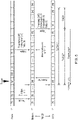
- the goal of the metrology system is to assert the SKIP or status output of the RMI-QE (i.e. the trigger signal output from the interface) a fixed latency after the probe receives a trigger.
- the latency must be as short as possible and have very low jitter.
- the latency is shown in the diagram as t LATENCY and is 2.5ms in this example.
- the frame timer on both the probe and interface is running at 250 ⁇ s, so there are 10 frames in the 2.5ms latency. This will allow 1 frame for the trigger, 1 "house keeping'" frame to allow the transmission to be scheduled, 1 frame for transmitting the message, and 7 frames for retries.
- the probe sends an ordinary periodic message to the RMI-QE interface.
- the periodic message from the probe is always sent at a specific offset within the frame (t PROBE_SEND ).
- the offset is 74 ⁇ s.
- the RMI-QE modem (interface) receives this message towards the end of the 75th microsecond, and it calculates the probe has drifted by -1 ⁇ s and needs to apply an adjustment of -1 ⁇ s (t ADJUST ) to bring the two frame timers into sync.
- the RMI-QE sends the adjustment message to the probe a few microseconds later, and the probe applies the adjustment, which takes effect at the end of the next frame.
- a trigger is received (t TRIGGER ); this is shown at 247 ⁇ s into the frame. Note that the adjustment to the frame length to bring it into line with the RMI-QE frame timer has not yet taken effect. To reduce jitter, it is clear from the diagram that although the trigger occurred at 247 ⁇ s on the probe frame timer, the RMI-QE needs to calculate that it occurred at 249 ⁇ s on its own frame timer.
- the probe On the second frame after the trigger occurred, the probe will send the timestamp (t TRIGGER ), the adjustment it applied (t ADJUST ), and the number of retries to the modem on the RMI-QE.
- t TRIGGER the timestamp
- t ADJUST the adjustment it applied
- t DRIFT the number of retries to the modem on the RMI-QE.
- no frame timer adjustments are applied in frames after a trigger event and before the event acknowledgment has been received from the RMI-QE interface. For example, if the trigger event occurs in the same frame as a periodic message containing a probe adjust value, the adjustment should not be applied. Instead, the interface will calculate the drift compensation required when it receives the event message and this will be used to correct the latency.
- the acknowledgment to the event message will contain an adjustment value for the probe and this can then be used to correct the clock in the probe.
- SPI serial peripheral interface
- t OFFSET consists of the offset within the frame that the FPGA will start the time t TIMER_START , 225 ⁇ s in the example), the distance of the timestamp (t TRIGGER ) from the end of the frame that it occurred in (t TRIGGER_INV ) and any retries that have occurred.
- t TIMERSTART_MAX 230 ⁇ s. If this is not possible then a drift allowance will need to be added to the timer to prevent a negative timer value being requested.
- t TIMER t LATENCY ⁇ t TIMER START ⁇ t TRIGGER INV ⁇ R ⁇ t FRAME
- t TRIGGER INV can be calculated by taking the trigger timestamp away from the frame length.
- the above technique thus permits clock adjustments to ensure the probe and interface clocks remain synchronised, but allows this to be done without impacting on metrology accuracy. In particular, the jitter previously seen due to the clock adjustment process is removed.
Landscapes
- Engineering & Computer Science (AREA)
- Computer Networks & Wireless Communication (AREA)
- Signal Processing (AREA)
- Physics & Mathematics (AREA)
- General Physics & Mathematics (AREA)
- Synchronisation In Digital Transmission Systems (AREA)
- Arrangements For Transmission Of Measured Signals (AREA)
Priority Applications (6)
| Application Number | Priority Date | Filing Date | Title |
|---|---|---|---|
| EP21168397.4A EP4075678A1 (de) | 2021-04-14 | 2021-04-14 | Funkkommunikationssystem für die metrologie |
| US18/283,250 US20240178879A1 (en) | 2021-04-14 | 2022-04-06 | A metrology radio communications system |
| CN202280028830.8A CN117178489A (zh) | 2021-04-14 | 2022-04-06 | 计量无线电通信系统 |
| PCT/GB2022/050855 WO2022219307A1 (en) | 2021-04-14 | 2022-04-06 | A metrology radio communications system |
| EP22715689.0A EP4324100A1 (de) | 2021-04-14 | 2022-04-06 | Metrologiefunkkommunikationssystem |
| JP2023563167A JP2024513612A (ja) | 2021-04-14 | 2022-04-06 | 計測無線通信システム |
Applications Claiming Priority (1)
| Application Number | Priority Date | Filing Date | Title |
|---|---|---|---|
| EP21168397.4A EP4075678A1 (de) | 2021-04-14 | 2021-04-14 | Funkkommunikationssystem für die metrologie |
Publications (1)
| Publication Number | Publication Date |
|---|---|
| EP4075678A1 true EP4075678A1 (de) | 2022-10-19 |
Family
ID=75529891
Family Applications (2)
| Application Number | Title | Priority Date | Filing Date |
|---|---|---|---|
| EP21168397.4A Withdrawn EP4075678A1 (de) | 2021-04-14 | 2021-04-14 | Funkkommunikationssystem für die metrologie |
| EP22715689.0A Pending EP4324100A1 (de) | 2021-04-14 | 2022-04-06 | Metrologiefunkkommunikationssystem |
Family Applications After (1)
| Application Number | Title | Priority Date | Filing Date |
|---|---|---|---|
| EP22715689.0A Pending EP4324100A1 (de) | 2021-04-14 | 2022-04-06 | Metrologiefunkkommunikationssystem |
Country Status (5)
| Country | Link |
|---|---|
| US (1) | US20240178879A1 (de) |
| EP (2) | EP4075678A1 (de) |
| JP (1) | JP2024513612A (de) |
| CN (1) | CN117178489A (de) |
| WO (1) | WO2022219307A1 (de) |
Citations (4)
| Publication number | Priority date | Publication date | Assignee | Title |
|---|---|---|---|---|
| WO2004057552A1 (en) | 2002-12-23 | 2004-07-08 | Renishaw Plc | Signal transmission system for a measurement device |
| EP2402714A1 (de) * | 2010-07-02 | 2012-01-04 | Tesa Sa | Vorrichtung zum Messen von Abmessungen |
| EP2901920A1 (de) * | 2012-09-25 | 2015-08-05 | Terumo Kabushiki Kaisha | System zur verarbeitung biologischer informationen, vorrichtung zur messung biologischer informationen, steuerungsvorrichtung, verfahren zu deren steuerung und speichermedium |
| WO2018134585A1 (en) | 2017-01-18 | 2018-07-26 | Renishaw Plc | Machine tool apparatus |
Family Cites Families (6)
| Publication number | Priority date | Publication date | Assignee | Title |
|---|---|---|---|---|
| GB2100944B (en) * | 1981-06-24 | 1985-03-06 | Racal Res Ltd | Synchronisation circuits |
| US5519717A (en) * | 1994-08-24 | 1996-05-21 | The United States Of America As Represented By The Secretary Of The Army | Method for time drift reduction of frequency hopping network clock |
| FI20001298A7 (fi) * | 2000-05-30 | 2001-12-01 | Nokia Corp | Kehyslähetysten synkronointi tietoliikenneverkossa |
| JP4577019B2 (ja) * | 2004-03-04 | 2010-11-10 | ソニー株式会社 | 無線通信システム、無線通信装置及び無線通信方法、並びにコンピュータ・プログラム |
| GB201116521D0 (en) * | 2011-09-23 | 2011-11-09 | Imagination Tech Ltd | Method and apparatus for time synchronisation in wireless networks |
| GB201222274D0 (en) * | 2012-12-11 | 2013-01-23 | Renishaw Plc | Radio interface |
-
2021
- 2021-04-14 EP EP21168397.4A patent/EP4075678A1/de not_active Withdrawn
-
2022
- 2022-04-06 EP EP22715689.0A patent/EP4324100A1/de active Pending
- 2022-04-06 CN CN202280028830.8A patent/CN117178489A/zh active Pending
- 2022-04-06 US US18/283,250 patent/US20240178879A1/en active Pending
- 2022-04-06 JP JP2023563167A patent/JP2024513612A/ja active Pending
- 2022-04-06 WO PCT/GB2022/050855 patent/WO2022219307A1/en not_active Ceased
Patent Citations (4)
| Publication number | Priority date | Publication date | Assignee | Title |
|---|---|---|---|---|
| WO2004057552A1 (en) | 2002-12-23 | 2004-07-08 | Renishaw Plc | Signal transmission system for a measurement device |
| EP2402714A1 (de) * | 2010-07-02 | 2012-01-04 | Tesa Sa | Vorrichtung zum Messen von Abmessungen |
| EP2901920A1 (de) * | 2012-09-25 | 2015-08-05 | Terumo Kabushiki Kaisha | System zur verarbeitung biologischer informationen, vorrichtung zur messung biologischer informationen, steuerungsvorrichtung, verfahren zu deren steuerung und speichermedium |
| WO2018134585A1 (en) | 2017-01-18 | 2018-07-26 | Renishaw Plc | Machine tool apparatus |
Also Published As
| Publication number | Publication date |
|---|---|
| JP2024513612A (ja) | 2024-03-26 |
| CN117178489A (zh) | 2023-12-05 |
| US20240178879A1 (en) | 2024-05-30 |
| EP4324100A1 (de) | 2024-02-21 |
| WO2022219307A1 (en) | 2022-10-20 |
Similar Documents
| Publication | Publication Date | Title |
|---|---|---|
| EP1576560B1 (de) | Signalübertragungssystem für eine messvorrichtung | |
| US20170041897A1 (en) | Apparatus and methods for synchronizing a controller and sensors | |
| CN104641589B (zh) | 校正参数计算装置及时刻同步系统、以及校正参数计算方法 | |
| CN110492965A (zh) | 一种主从系统内串行报文对时的方法和装置 | |
| KR20180071268A (ko) | 제어기와 센서들을 동기화하기 위한 장치 및 방법들 | |
| US11419084B1 (en) | Time synchronization in hybrid wired-wireless time-sensitive networking | |
| WO2023057441A1 (en) | Device and method for clock synchronisation in a wireless network | |
| EP4075678A1 (de) | Funkkommunikationssystem für die metrologie | |
| JP2012195840A (ja) | 通信装置、通信制御方法 | |
| CN102710359A (zh) | 一种基于ieee1588的精确时钟频率同步方法及装置 | |
| US7249272B1 (en) | Apparatus and method for coordinating activities of one or more computers | |
| JP5626589B2 (ja) | ネットワーク機器、および同機器における時刻同期方法 | |
| CN118019099B (zh) | 一种提高精度的无线时间同步方法 | |
| US20240171214A1 (en) | A measurement device and a measurement interface having a radio communications module | |
| US20240171213A1 (en) | Radio communications apparatus for a measurement system | |
| WO2020100374A1 (ja) | 遅延時間検出回路、打刻情報生成装置および遅延時間検出方法 | |
| JP2017175309A (ja) | 通信システム | |
| CN114116579B (zh) | 信息处理装置、信息处理系统以及信息处理方法 | |
| JP3571218B2 (ja) | 同期動作システム | |
| JP2024513612A5 (de) | ||
| JP2020053842A (ja) | 通信装置、集約装置、通信システムおよび制御プログラム |
Legal Events
| Date | Code | Title | Description |
|---|---|---|---|
| PUAI | Public reference made under article 153(3) epc to a published international application that has entered the european phase |
Free format text: ORIGINAL CODE: 0009012 |
|
| STAA | Information on the status of an ep patent application or granted ep patent |
Free format text: STATUS: THE APPLICATION HAS BEEN PUBLISHED |
|
| AK | Designated contracting states |
Kind code of ref document: A1 Designated state(s): AL AT BE BG CH CY CZ DE DK EE ES FI FR GB GR HR HU IE IS IT LI LT LU LV MC MK MT NL NO PL PT RO RS SE SI SK SM TR |
|
| STAA | Information on the status of an ep patent application or granted ep patent |
Free format text: STATUS: THE APPLICATION IS DEEMED TO BE WITHDRAWN |
|
| 18D | Application deemed to be withdrawn |
Effective date: 20230420 |