EP4075683A1 - Procédé de transmission - Google Patents
Procédé de transmission Download PDFInfo
- Publication number
- EP4075683A1 EP4075683A1 EP22160664.3A EP22160664A EP4075683A1 EP 4075683 A1 EP4075683 A1 EP 4075683A1 EP 22160664 A EP22160664 A EP 22160664A EP 4075683 A1 EP4075683 A1 EP 4075683A1
- Authority
- EP
- European Patent Office
- Prior art keywords
- reference signal
- network device
- terminal
- resource
- dci
- Prior art date
- Legal status (The legal status is an assumption and is not a legal conclusion. Google has not performed a legal analysis and makes no representation as to the accuracy of the status listed.)
- Granted
Links
Images

Classifications
-
- H—ELECTRICITY
- H04—ELECTRIC COMMUNICATION TECHNIQUE
- H04L—TRANSMISSION OF DIGITAL INFORMATION, e.g. TELEGRAPHIC COMMUNICATION
- H04L5/00—Arrangements affording multiple use of the transmission path
- H04L5/003—Arrangements for allocating sub-channels of the transmission path
- H04L5/0048—Allocation of pilot signals, i.e. of signals known to the receiver
-
- H—ELECTRICITY
- H04—ELECTRIC COMMUNICATION TECHNIQUE
- H04B—TRANSMISSION
- H04B7/00—Radio transmission systems, i.e. using radiation field
- H04B7/02—Diversity systems; Multi-antenna system, i.e. transmission or reception using multiple antennas
- H04B7/04—Diversity systems; Multi-antenna system, i.e. transmission or reception using multiple antennas using two or more spaced independent antennas
- H04B7/06—Diversity systems; Multi-antenna system, i.e. transmission or reception using multiple antennas using two or more spaced independent antennas at the transmitting station
- H04B7/0613—Diversity systems; Multi-antenna system, i.e. transmission or reception using multiple antennas using two or more spaced independent antennas at the transmitting station using simultaneous transmission
- H04B7/0615—Diversity systems; Multi-antenna system, i.e. transmission or reception using multiple antennas using two or more spaced independent antennas at the transmitting station using simultaneous transmission of weighted versions of same signal
- H04B7/0617—Diversity systems; Multi-antenna system, i.e. transmission or reception using multiple antennas using two or more spaced independent antennas at the transmitting station using simultaneous transmission of weighted versions of same signal for beam forming
-
- H—ELECTRICITY
- H04—ELECTRIC COMMUNICATION TECHNIQUE
- H04B—TRANSMISSION
- H04B7/00—Radio transmission systems, i.e. using radiation field
- H04B7/02—Diversity systems; Multi-antenna system, i.e. transmission or reception using multiple antennas
- H04B7/04—Diversity systems; Multi-antenna system, i.e. transmission or reception using multiple antennas using two or more spaced independent antennas
- H04B7/06—Diversity systems; Multi-antenna system, i.e. transmission or reception using multiple antennas using two or more spaced independent antennas at the transmitting station
- H04B7/0613—Diversity systems; Multi-antenna system, i.e. transmission or reception using multiple antennas using two or more spaced independent antennas at the transmitting station using simultaneous transmission
- H04B7/0615—Diversity systems; Multi-antenna system, i.e. transmission or reception using multiple antennas using two or more spaced independent antennas at the transmitting station using simultaneous transmission of weighted versions of same signal
- H04B7/0619—Diversity systems; Multi-antenna system, i.e. transmission or reception using multiple antennas using two or more spaced independent antennas at the transmitting station using simultaneous transmission of weighted versions of same signal using feedback from receiving side
-
- H—ELECTRICITY
- H04—ELECTRIC COMMUNICATION TECHNIQUE
- H04B—TRANSMISSION
- H04B7/00—Radio transmission systems, i.e. using radiation field
- H04B7/02—Diversity systems; Multi-antenna system, i.e. transmission or reception using multiple antennas
- H04B7/04—Diversity systems; Multi-antenna system, i.e. transmission or reception using multiple antennas using two or more spaced independent antennas
- H04B7/06—Diversity systems; Multi-antenna system, i.e. transmission or reception using multiple antennas using two or more spaced independent antennas at the transmitting station
- H04B7/0613—Diversity systems; Multi-antenna system, i.e. transmission or reception using multiple antennas using two or more spaced independent antennas at the transmitting station using simultaneous transmission
- H04B7/0615—Diversity systems; Multi-antenna system, i.e. transmission or reception using multiple antennas using two or more spaced independent antennas at the transmitting station using simultaneous transmission of weighted versions of same signal
- H04B7/0619—Diversity systems; Multi-antenna system, i.e. transmission or reception using multiple antennas using two or more spaced independent antennas at the transmitting station using simultaneous transmission of weighted versions of same signal using feedback from receiving side
- H04B7/0621—Feedback content
- H04B7/0626—Channel coefficients, e.g. channel state information [CSI]
-
- H—ELECTRICITY
- H04—ELECTRIC COMMUNICATION TECHNIQUE
- H04B—TRANSMISSION
- H04B7/00—Radio transmission systems, i.e. using radiation field
- H04B7/02—Diversity systems; Multi-antenna system, i.e. transmission or reception using multiple antennas
- H04B7/04—Diversity systems; Multi-antenna system, i.e. transmission or reception using multiple antennas using two or more spaced independent antennas
- H04B7/06—Diversity systems; Multi-antenna system, i.e. transmission or reception using multiple antennas using two or more spaced independent antennas at the transmitting station
- H04B7/0613—Diversity systems; Multi-antenna system, i.e. transmission or reception using multiple antennas using two or more spaced independent antennas at the transmitting station using simultaneous transmission
- H04B7/0615—Diversity systems; Multi-antenna system, i.e. transmission or reception using multiple antennas using two or more spaced independent antennas at the transmitting station using simultaneous transmission of weighted versions of same signal
- H04B7/0619—Diversity systems; Multi-antenna system, i.e. transmission or reception using multiple antennas using two or more spaced independent antennas at the transmitting station using simultaneous transmission of weighted versions of same signal using feedback from receiving side
- H04B7/0621—Feedback content
- H04B7/063—Parameters other than those covered in groups H04B7/0623 - H04B7/0634, e.g. channel matrix rank or transmit mode selection
-
- H—ELECTRICITY
- H04—ELECTRIC COMMUNICATION TECHNIQUE
- H04B—TRANSMISSION
- H04B7/00—Radio transmission systems, i.e. using radiation field
- H04B7/02—Diversity systems; Multi-antenna system, i.e. transmission or reception using multiple antennas
- H04B7/04—Diversity systems; Multi-antenna system, i.e. transmission or reception using multiple antennas using two or more spaced independent antennas
- H04B7/06—Diversity systems; Multi-antenna system, i.e. transmission or reception using multiple antennas using two or more spaced independent antennas at the transmitting station
- H04B7/0613—Diversity systems; Multi-antenna system, i.e. transmission or reception using multiple antennas using two or more spaced independent antennas at the transmitting station using simultaneous transmission
- H04B7/0615—Diversity systems; Multi-antenna system, i.e. transmission or reception using multiple antennas using two or more spaced independent antennas at the transmitting station using simultaneous transmission of weighted versions of same signal
- H04B7/0619—Diversity systems; Multi-antenna system, i.e. transmission or reception using multiple antennas using two or more spaced independent antennas at the transmitting station using simultaneous transmission of weighted versions of same signal using feedback from receiving side
- H04B7/0636—Feedback format
- H04B7/0639—Using selective indices, e.g. of a codebook, e.g. pre-distortion matrix index [PMI] or for beam selection
-
- H—ELECTRICITY
- H04—ELECTRIC COMMUNICATION TECHNIQUE
- H04L—TRANSMISSION OF DIGITAL INFORMATION, e.g. TELEGRAPHIC COMMUNICATION
- H04L1/00—Arrangements for detecting or preventing errors in the information received
- H04L1/0001—Systems modifying transmission characteristics according to link quality, e.g. power backoff
- H04L1/0023—Systems modifying transmission characteristics according to link quality, e.g. power backoff characterised by the signalling
- H04L1/0027—Scheduling of signalling, e.g. occurrence thereof
-
- H—ELECTRICITY
- H04—ELECTRIC COMMUNICATION TECHNIQUE
- H04L—TRANSMISSION OF DIGITAL INFORMATION, e.g. TELEGRAPHIC COMMUNICATION
- H04L5/00—Arrangements affording multiple use of the transmission path
- H04L5/003—Arrangements for allocating sub-channels of the transmission path
- H04L5/0048—Allocation of pilot signals, i.e. of signals known to the receiver
- H04L5/0051—Allocation of pilot signals, i.e. of signals known to the receiver of dedicated pilots, i.e. pilots destined for a single user or terminal
-
- H—ELECTRICITY
- H04—ELECTRIC COMMUNICATION TECHNIQUE
- H04L—TRANSMISSION OF DIGITAL INFORMATION, e.g. TELEGRAPHIC COMMUNICATION
- H04L5/00—Arrangements affording multiple use of the transmission path
- H04L5/003—Arrangements for allocating sub-channels of the transmission path
- H04L5/0053—Allocation of signalling, i.e. of overhead other than pilot signals
-
- H—ELECTRICITY
- H04—ELECTRIC COMMUNICATION TECHNIQUE
- H04L—TRANSMISSION OF DIGITAL INFORMATION, e.g. TELEGRAPHIC COMMUNICATION
- H04L5/00—Arrangements affording multiple use of the transmission path
- H04L5/0091—Signalling for the administration of the divided path, e.g. signalling of configuration information
- H04L5/0094—Indication of how sub-channels of the path are allocated
-
- H—ELECTRICITY
- H04—ELECTRIC COMMUNICATION TECHNIQUE
- H04W—WIRELESS COMMUNICATION NETWORKS
- H04W24/00—Supervisory, monitoring or testing arrangements
- H04W24/10—Scheduling measurement reports ; Arrangements for measurement reports
-
- H—ELECTRICITY
- H04—ELECTRIC COMMUNICATION TECHNIQUE
- H04W—WIRELESS COMMUNICATION NETWORKS
- H04W56/00—Synchronisation arrangements
- H04W56/001—Synchronization between nodes
-
- H—ELECTRICITY
- H04—ELECTRIC COMMUNICATION TECHNIQUE
- H04W—WIRELESS COMMUNICATION NETWORKS
- H04W72/00—Local resource management
- H04W72/04—Wireless resource allocation
- H04W72/044—Wireless resource allocation based on the type of the allocated resource
- H04W72/046—Wireless resource allocation based on the type of the allocated resource the resource being in the space domain, e.g. beams
-
- H—ELECTRICITY
- H04—ELECTRIC COMMUNICATION TECHNIQUE
- H04W—WIRELESS COMMUNICATION NETWORKS
- H04W72/00—Local resource management
- H04W72/20—Control channels or signalling for resource management
- H04W72/23—Control channels or signalling for resource management in the downlink direction of a wireless link, i.e. towards a terminal
Definitions
- This application relates to the communications field, and more specifically, to a transmission method, a network device, and a terminal.
- a terminal performs channel estimation by using a reference signal sent by a network device, and after obtaining state information of a downlink channel, the terminal feeds back the channel state information (channel state information, CSI) to the network device.
- the terminal may feed back a precoding matrix index (precoding matrix index, PMI), a rank index (rank index, RI), and a channel quality index (channel quality index, CQI) to the network device, and the network device sends data based on the information.
- precoding matrix index precoding matrix index, PMI
- rank index rank index
- CQI channel quality index
- the network device may perform beam management (beam management) by using a reference signal.
- the network device repeatedly sends the reference signal in different time units, and the terminal performs receive beam training in different time units by using different receive beams (beam). In this case, the terminal does not need to report a measurement result of the reference signal.
- This application provides a transmission method, a network device, and a terminal, to save resources.
- a transmission method includes: determining, by a network device, downlink control information (downlink control information, DCI), wherein the DCI includes a first request field, information in the first request field is only used to instruct to send a first reference signal on a first resource, or the information in the first request field is used to instruct to send the first reference signal on the first resource and instruct a terminal to report a measurement result of the first reference signal on the first resource, and the measurement result includes channel state information CSI and/or beam state information (beam state information, BSI); and sending, by the network device, the DCI to the terminal.
- DCI downlink control information
- BSI beam state information
- the beam state information BSI may include information such as reference signal received power (reference signal received power, RSRP), a beam index, or an identity (identity, ID).
- RSRP reference signal received power
- ID identity
- the first reference signal may be a secondary synchronization signal (secondary synchronization signal, SSS), a primary synchronization signal (primary synchronization signal, PSS), a channel state information reference signal (channel state information reference signal, CSI-RS), or a demodulation reference signal (demodulation reference signal, DMRS).
- secondary synchronization signal secondary synchronization signal
- PSS primary synchronization signal
- PSS primary synchronization signal
- channel state information reference signal channel state information reference signal
- CSI-RS channel state information reference signal
- demodulation reference signal demodulation reference signal
- the PSS and/or the SSS may be sent in a form of an SS block. That is, the PSS, the SSS, and a physical broadcast channel (physical broadcast channel, PBCH) are sent at different time in an SS block, or the PSS and/or the SSS may not be sent in an SS block, that is, the PSS and/or the SSS may be separately sent.
- a physical broadcast channel physical broadcast channel, PBCH
- the first request field may be a CSI request field (value of CSI request field) in an existing DCI format.
- the DCI format can be less modified and better compatible with the prior art.
- the network device when the terminal does not need to report a measurement result of a reference signal (for example, the first reference signal), the network device instructs the terminal not to report the measurement result. Because the terminal does not need to report the measurement result, the network device does not allocate a resource to the terminal for reporting the measurement result, so that the resource can be saved.
- a reference signal for example, the first reference signal
- a format of the DCI is a first format, and the DCI satisfying the first format is used for downlink data transmission; and the information in the first request field is only used to instruct to send the first reference signal.
- the format of the DCI is a second format, and the DCI satisfying the second format is used for uplink data transmission; and the information in the first request field instructs to send the first reference signal and instructs the terminal to report the measurement result of the first reference signal.
- the first format may alternatively be a newly-defined DCI format (for example, denoted as a third format).
- the third format is different from the existing DCI format, and the DCI satisfying the third format may include only the first request field and a scheduling information field, or may include only the first request field.
- Information in the scheduling information field is used to indicate downlink data scheduling information of the terminal. The terminal can determine, based on the information in the scheduling information field, a resource that is occupied by downlink data sent by the network device.
- the first request field in the DCI may trigger reporting of the CSI, or the first request field in the DCI may trigger reporting of the BSI, or the first request field in the DCI triggers reporting of both the CSI and the BSI.
- Specific state information that needs to be reported by the terminal may be configured by using higher layer signaling.
- the network device may configure, by using the higher layer signaling, the specific state information to be reported by the terminal.
- the higher layer signaling in this application may be radio resource control (radio resource control, RRC) signaling or Media Access Control control signaling (media access control control element, MAC CE) signaling.
- RRC radio resource control
- MAC CE Media Access Control control element
- the network device may trigger, by selecting different DCIs, the terminal to perform a corresponding operation.
- the method improves flexibility of the DCI.
- the first resource is a first reference signal resource set in S first reference signal resource sets;
- the first request field occupies ⁇ log 2 ( T ) ⁇ bits, a value of T is any one of S, S+1, SN , and SN+1, and ⁇ ⁇ represents rounding up.
- the S first reference signal resource sets may be configured by the network device for the terminal by using at least one of higher layer signaling, layer 2 signaling, and layer 1 signaling.
- a layer 2 herein means a MAC layer
- a layer 1 is a physical layer.
- the first resource triggered by the DCI for example, the 1 st reference signal resource in the 1 st first reference signal resource set, or the first reference signal resource set, may be information such as a location of the first reference signal, a quantity of ports for sending the first reference signal, and port numbers of the ports for sending the first reference signal.
- the method may further include: sending, by the network device, power information to the terminal, wherein the power information is used by the terminal to determine transmit power of the first reference signal.
- the network device may send the power information by using a broadcast channel, system information, or higher layer signaling.
- the terminal may determine the transmit power of the first reference signal based on the power information, so that the terminal may control uplink power based on the transmit power of the first reference signal, thereby improving accuracy of a channel measurement result.
- the power information is used to indicate a power ratio of the first reference signal to a second reference signal.
- the second reference signal may be an SSS.
- X may alternatively be a predefined value, and Z is configurable.
- the network device may determine, based on the foregoing formula, whether a measurement report currently sent by the terminal is a measurement report for a first reference signal that is last sent by the network device. In this way, the network device may send data by using a latest measurement result, thereby improving transmission performance.
- a transmission method includes: receiving, by a terminal, downlink control information DCI sent by a network device, wherein the DCI includes a first request field, information in the first request field is only used to instruct to send a first reference signal on a first resource, or the information in the first request field is used to instruct to send the first reference signal on the first resource and instruct the terminal to report a measurement result of the first reference signal on the first resource, and the measurement result includes channel state information CSI and/or beam state information BSI; and determining, by the terminal based on the DCI, whether to report the measurement result.
- DCI downlink control information
- the DCI includes a first request field, information in the first request field is only used to instruct to send a first reference signal on a first resource, or the information in the first request field is used to instruct to send the first reference signal on the first resource and instruct the terminal to report a measurement result of the first reference signal on the first resource, and the measurement result includes channel state information CSI and/or beam state information BSI; and determining
- the first reference signal may be an SSS, a PSS, a CSI-RS, or a demodulation reference signal.
- the PSS and/or the SSS may be sent in a form of an SS block. That is, the PSS, the SSS, and a physical broadcast channel PBCH are sent at different time in an SS block, or the PSS and/or the SSS may not be sent in an SS block, that is, the PSS and/or the SSS may be separately sent.
- the first request field may be a CSI request field (value of CSI request field) in an existing DCI format.
- the DCI format can be less modified and better compatible with the prior art.
- the network device when the terminal does not need to report a measurement result of a reference signal (for example, the first reference signal), the network device instructs the terminal not to report the measurement result. Because the terminal does not need to report the measurement result, the network device does not allocate a resource to the terminal for reporting the measurement result, so that the resource can be saved.
- a reference signal for example, the first reference signal
- a format of the DCI is a first format, and the DCI satisfying the first format is used for downlink data transmission; and the information in the first request field is only used to instruct to send the first reference signal.
- the format of the DCI is a second format, and the DCI satisfying the second format is used for uplink data transmission; and the information in the first request field instructs to send the first reference signal and instructs the terminal to report the measurement result of the first reference signal.
- the network device may trigger, by selecting different DCIs, the terminal to perform a corresponding operation.
- the method improves flexibility of the DCI.
- the first resource is a first reference signal resource set in S first reference signal resource sets;
- the first request field occupies ⁇ log 2 ( T ) ⁇ bits, a value of T is any one of S, S+1, SN , and SN +1, and ⁇ ⁇ represents rounding up.
- the S first reference signal resource sets may be configured by the network device for the terminal by using at least one of higher layer signaling, layer 2 signaling, and layer 1 signaling.
- a layer 2 herein means a MAC layer
- a layer 1 is a physical layer.
- the first resource triggered by the DCI for example, the 1 st first reference signal resource set, the 1 st first reference signal resource in the first reference signal resource set, or the 1 st group of first reference signal resources in the first reference signal resource set, may be information such as a time-frequency resource location of the first reference signal, a quantity of ports for sending the first reference signal, and port numbers of the ports for sending the first reference signal.
- the method may further include: receiving, by the terminal, power information sent by the network device; and determining, by the terminal, transmit power of the first reference signal based on the power information.
- the terminal may receive, by using a broadcast channel, system information, or higher layer signaling, the power information sent by the network device.
- the terminal may determine the transmit power of the first reference signal based on the power information, so that the terminal may control uplink power based on the transmit power of the first reference signal, thereby improving accuracy of a channel measurement result.
- the power information is used to indicate a power ratio of the first reference signal to a second reference signal.
- the second reference signal may be an SSS.
- X may alternatively be a predefined value, and Z is configurable.
- the network device may determine, based on the foregoing formula, whether a measurement report currently sent by the terminal is a measurement report for a first reference signal that is last sent by the network device. In this way, the network device may send data by using a latest measurement result, thereby improving transmission performance.
- a network device configured to perform the method according to the first aspect or any possible implementation of the first aspect.
- the network device includes units configured to perform the method according to the first aspect or any possible implementation of the first aspect.
- a terminal configured to perform the method according to the second aspect or any possible implementation of the second aspect.
- the terminal includes units configured to perform the method according to the second aspect or any possible implementation of the second aspect.
- a network device includes a transceiver, a memory, and a processor.
- the memory is configured to store a computer program
- the processor is configured to invoke the computer program from the memory and execute the computer program, so that a system performs the method according to the first aspect or any possible implementation of the first aspect.
- a terminal includes a transceiver, a memory, and a processor.
- the memory is configured to store a computer program
- the processor is configured to invoke the computer program from the memory and execute the computer program, so that a system performs the method according to the second aspect or any possible implementation of the second aspect.
- a computer readable storage medium configured to store a computer program, wherein the computer program includes instructions used to perform the method according to the foregoing aspects or any possible implementation of the foregoing aspects.
- a computer program product including an instruction is provided.
- the computer program product runs on a computer, the computer is enabled to perform the method according to the foregoing aspects or any possible implementation of the foregoing aspects.
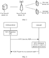
- FIG. 1 is a schematic diagram of an architecture of a mobile communications system applied to embodiments of this application.
- the mobile communications system includes a core network device 110, an access network device 120, and at least one terminal device (a terminal device 130 and a terminal device 140 shown in FIG. 1 ).
- the terminal device is connected to the access network device 120 in a wireless manner
- the access network device 120 is connected to the core network device 110 in a wired or wireless manner.
- the core network device 110 and the access network device 120 may be different independent physical devices, or functions of the core network device 110 and logical functions of the access network device may be integrated into one physical device, or one physical device integrates some functions of the core network device 210 and some functions of the access network device 120.
- the terminal device may be disposed at fixed positions, or may be movable.
- FIG. 1 is only a schematic diagram, and the communications system may further include other network devices, for example, a wireless relay device and a wireless backhaul device (not shown in FIG. 1 ).
- quantities of core network devices, access network devices, and terminal devices included in the mobile communications system are not limited.
- the access network device 120 is an access device used by the terminal device to access the mobile communications system in a wireless manner.
- the access network device 120 may be a nodeB (nodeB, NB), an evolved nodeB (evolved nodeB, eNB), a base station in a 5G mobile communications system, a base station in a new radio (new radio, NR) communications system, a base station in a future mobile communications system, an access node in a Wi-Fi system, or the like.
- a specific technology and a specific device form used by a wireless access network device are not limited in the embodiments of this application. Unless otherwise stated, in this application, expressions of a 5G system and an NR system are interchangeable.
- the terminal device may also be referred to as a terminal (Terminal), user equipment (user equipment, UE), a mobile station (mobile station, MS), a mobile terminal (mobile terminal, MT), or the like.
- the terminal device may be a mobile phone (mobile phone), a tablet computer (Pad), a computer having wireless sending and receiving functions, a virtual reality (virtual reality, VR) terminal device, an augmented reality (augmented reality, AR) terminal device, a wireless terminal in industrial control (industrial control), a wireless terminal in self-driving (self-driving), a wireless terminal in remote medical surgery (remote medical surgery), a wireless terminal in a smart grid (smart grid), a wireless terminal in transportation safety (transportation safety), a wireless terminal in a smart city (smart city), a wireless terminal in a smart home (smart home), or the like.
- the access network device and the terminal device may be deployed terrestrially, including indoors or outdoors, or may be handheld or vehicle-mounted; or may be deployed on a water surface; or may be deployed on a plane, a balloon, or a man-made satellite in the sky.
- Application scenarios of the access network device and the terminal device are not limited in the embodiments of this application.
- the access network device may communicate with the terminal device and one terminal device may communicate with another terminal device by using either a licensed spectrum (licensed spectrum) or an unlicensed spectrum (unlicensed spectrum), or by using both a licensed spectrum and an unlicensed spectrum.
- the access network device may communicate with the terminal device and one terminal device may communicate with another terminal device by using either a spectrum below 6 gigahertz (gigahertz, GHz) or a spectrum above 6 GHz, or by using both a spectrum below 6 GHz and a spectrum above 6 GHz.
- Spectrum resources used between the access network device and the terminal device are not limited in the embodiments of this application.
- a network device in the following description may be the access network device in the foregoing description, or may be another network device that communicates with the terminal in a wireless manner. This is not limited in this application.
- a terminal performs channel estimation by using a reference signal sent by a network device, and after obtaining state information of a downlink channel, the terminal feeds back CSI to the network device. For example, the terminal may feed back a PMI, an RI, and a CQI to the network device, and the network device sends data based on the information.
- the network device may perform beam management by using a reference signal.
- the network device repeatedly sends the reference signal in different time units, and the terminal performs receive beam training in different time units by using different receive beams. In this case, the terminal does not need to report a measurement result of the reference signal.
- this application provides a transmission method.
- the transmission method in this application when the terminal does not need to report a measurement result (for example, beam state information BSI) that is obtained by measuring a reference signal, the network device instructs the terminal not to report the measurement result. Because the terminal does not need to report the measurement result, the network device does not allocate a resource to the terminal for reporting the measurement result, so that the resource can be saved.
- a measurement result for example, beam state information BSI
- first and second in the embodiments of this application are merely used for distinguishing purposes, and are not intended to constitute any limitation on the present invention.
- a first reference signal and a second reference signal are merely used for distinguishing between different types of reference signals.
- FIG. 2 is a schematic flowchart of a transmission method according to an embodiment of the present invention from a perspective of device interaction.
- a network device in FIG. 2 may be the wireless access network device 120 in FIG. 1
- a terminal device in FIG. 2 may be the terminal device 130 or the terminal device 140 in FIG. 1 .
- the network device determines downlink control information DCI.
- the DCI includes a first request field, and information in the first request field is only used to instruct to send a first reference signal on a first resource, or the information in the first request field may instruct to send the first reference signal on the first resource and instruct the terminal to report a measurement result of the first reference signal on the first resource.
- the network device determines whether to trigger the sending of the first reference signal, that is, whether to send the first reference signal to the terminal. If determining to send the first reference signal to the terminal, the network device determines a resource (for example, denoted as the first resource) used for sending the first reference signal, and determines whether the terminal needs to report the measurement result of the first reference signal (referred to as the measurement result below) corresponding to the first resource.
- the network device determines the DCI based on the foregoing determining result, and indicates, to the terminal based on the information in the first request field in the DCI, the first resource and an operation that needs to be performed by the terminal. That is, the first request field only instructs to send the first reference signal on the first resource (that is, Case 1), or the first request field instructs to send the first reference signal and instructs to send the measurement result (that is, Case 2).
- the information in the first request field is only used to instruct to send the first reference signal on the first resource, but not to instruct the terminal to report the measurement result of the first reference signal on the first resource. That is, the information in the first request field is used to indicate to the terminal that the network device sends the first reference signal on the first resource, and the terminal does not need to report the measurement result of the first reference signal on the first resource. In other words, the first request field instructs to send the first reference signal on the first resource and instructs the terminal not to report the measurement result.
- the network device instructs the terminal not to report the measurement result. Because the terminal does not need to report the measurement result, the network device does not allocate a resource to the terminal for reporting the measurement result, so that the resource can be saved.
- a reference signal for example, the first reference signal
- a format of the DCI may be a first format.
- the DCI satisfying the first format is used for downlink data transmission.
- the network device when the network device performs beam management and the terminal performs receive beam training, the network device only needs to trigger an aperiodic first reference signal and does not require the terminal to report the measurement result.
- the network device may use the DCI in the first format, and based on instruction of the information in a first request field in the DCI in the first format, the network device sends the first reference signal and does not require the terminal to report the measurement result.
- the first format may be a DCI format 2.
- the first format may alternatively be a newly-defined DCI format (for example, denoted as a third format).
- the third format is different from the existing DCI format, and the DCI satisfying the third format may include only the first request field and a scheduling information field, or may include only the first request field.
- Information in the scheduling information field is used to indicate downlink data scheduling information of the terminal. The terminal can determine, based on the information in the scheduling information field, a resource that is occupied by downlink data sent by the network device.
- the first format is not limited to the DCI formats listed above, but the first format may alternatively be a DCI format defined in a 5G system or a future new system.
- the information in the first request field not only indicates to the terminal that the network device sends the first reference signal on the first resource, but also indicates to the terminal that the terminal needs to report the measurement result of the first reference signal that is sent on the first resource.
- the measurement result includes channel state information CSI and/or beam state information BSI.
- the first request field in the DCI may trigger reporting of the CSI, or the first request field in the DCI may trigger reporting of the BSI, or the first request field in the DCI triggers reporting of both the CSI and the BSI.
- Specific state information that needs to be reported by the terminal may be configured by using higher layer signaling. In other words, the network device may configure, by using the higher layer signaling, the specific state information to be reported by the terminal.
- the beam state information BSI may include information such as reference signal received power RSRP, a beam index, or an ID.
- a format of the DCI is a second format.
- the DCI satisfying the second format is used for uplink data transmission.
- the network device may trigger, by using the DCI in the second format, both sending of an aperiodic first reference signal and reporting of a measurement result of the aperiodic first reference signal.
- the terminal reports the measurement result based on the DCI and an instruction of higher layer signaling.
- the second format may be a DCI format 0 or a DCI format 4, or a DCI format in any other form. This is not specifically limited herein.
- the second format is not limited to the DCI formats listed above, but the second format may alternatively be a DCI format defined in a 5G system or a future new system.
- the first request field may be a CSI request field (value of CSI request field) in an existing DCI format.
- the existing DCI format the DCI format can be less modified and better compatible with the prior art.
- the first request field may alternatively be a newly-defined request field. This is not limited herein.
- the first reference signal may be a secondary synchronization signal (secondary synchronization signal, SSS), a primary synchronization signal (primary synchronization signal, PSS), a channel state information reference signal (channel state information reference signal, CSI-RS), or a demodulation reference signal (demodulation reference signal, DMRS).
- secondary synchronization signal secondary synchronization signal
- PSS primary synchronization signal
- PSS primary synchronization signal
- channel state information reference signal channel state information reference signal
- CSI-RS channel state information reference signal
- demodulation reference signal demodulation reference signal
- the PSS and/or the SSS may be sent in a form of an SS block. That is, the PSS, the SSS, and a physical broadcast channel PBCH are sent at different time in an SS block, or the PSS and/or the SSS may not be sent in an SS block, that is, the PSS and/or the SSS may be separately sent.
- first reference signal is not specifically limited in this application, but the first reference signal may alternatively be another reference signal that may emerge in the future.
- the network device when the terminal does not need to report a measurement result (for example, BSI and/or CSI) that is obtained by measuring a reference signal, the network device instructs the terminal not to report the measurement result. Because the terminal does not need to report the measurement result, the network device does not allocate a resource to the terminal for reporting the measurement result, so that the resource can be saved.
- a measurement result for example, BSI and/or CSI
- the network device may trigger, by selecting different DCIs, the terminal to perform a corresponding operation.
- the method improves flexibility of the DCI.
- the first resource may be a first reference signal resource set in S first reference signal resource sets.
- the first reference signal resource set includes N groups of first reference signal resources or at least one first reference signal resource, a group of first reference signal resources includes at least one first reference signal resource, and both S and N are integers greater than or equal to 1.
- the S first reference signal resource sets may be configured by the network device for the terminal by using at least one of higher layer signaling, layer 2 signaling, and layer 1 signaling, and may be triggered by the DCI.
- the first resource triggered by the DCI may be a first reference signal resource set in the S first reference signal resource sets. That is, the first reference signal sent by the network device is a first reference signal corresponding to all first reference signal resources that are included in the first reference signal resource set.
- the resource triggered by the DCI for example, may be information such as a time-frequency resource location of the first reference signal, a quantity of ports for sending the first reference signal, and port numbers of the ports for sending the first reference signal.
- the terminal may measure the first reference signal based on the resource information.
- the first request field may occupy ⁇ log 2 ( T ) ⁇ bits, a value of T is any one of S, S+1, SN , or SN+1, and ⁇ ⁇ represents rounding up.
- the higher layer signaling in this application may be RRC signaling, MAC CE signaling, or the like.
- Table 1 shows an example of Case 1, and information in a first request field shown in Table 1 only instructs to send a first reference signal on a first reference signal resource set.
- Table 1 Value of a first Request Field (Information in a First Request Field) Description 000 Not triggering sending of a first reference signal 001 Trigger sending of a first reference signal corresponding to the 1 st first reference signal resource set in S first reference signal resource sets 010
- Trigger sending of a first reference signal corresponding to the 4 th first reference signal resource set in S first reference signal resource sets 101 Trigger sending of a first reference signal corresponding to the 5 th first reference signal resource set in S first reference signal resource sets 110
- step S210 if the value of the first request field in the DCI determined by the network device is "000", it indicates that the sending of the first reference signal is not triggered; or if the value of the first request field in the DCI is "001", it indicates that the network device is to send the first reference signal on the 1 st first reference signal resource set in the S first reference signal resource sets and the terminal does not need to report the measurement result of the first reference signal sent on all resources that are included in the first reference signal resource.
- Table 2 shows an example of Case 2, and the information in the first request field shown in Table 2 is used to instruct to send the first reference signal on the first reference signal resource in the first reference signal resource set and instruct to report the measurement result.
- the value of the first request field in the DCI determined by the network device is "000", it indicates that the network device does not trigger the sending of the first reference signal and the reporting of the measurement result.
- the value of the first request field is "001”
- the first resource may be a first reference signal resource or a group of first reference signal resources in a first reference signal resource set in the S first reference signal resource sets.
- the first reference signal resource set includes at least one first reference signal resource or N groups of first reference signal resources, a group of first reference signal resources includes at least one first reference signal resource, and both S and N are integers greater than or equal to 1.
- the S first reference signal resource sets may be configured by the network device for the terminal by using at least one of higher layer signaling, layer 2 signaling, and layer 1 signaling, and may be triggered by the DCI.
- the first resource triggered by the DCI may be a first reference signal resource in a first reference signal resource set in the S first reference signal resource sets, or a group of first reference signal resources in a first reference signal resource set in the S first reference signal resource sets, for example, the 1 st first reference signal resource in the 1 st first reference signal resource set or the 1 st group of first reference signal resources in the 1 st first reference signal resource set.
- the resource triggered by the DCI may be information such as a time-frequency resource location of the first reference signal, a quantity of ports for sending the first reference signal, and port numbers of the ports for sending the first reference signal.
- the terminal may measure the first reference signal based on the resource information.
- the network device may indicate, by using the higher layer signaling, the first reference signal resource set in the S first reference signal resource sets triggered by the network device.
- the network device may indicate, by using the higher layer signaling, the 1 st first reference signal resource set in the S first reference signal resource sets triggered by the network device.
- the first request field occupies ⁇ log 2 ( T ) ⁇ bits, a value of T is any one of S, S+1, SN , or SN+1, and ⁇ ⁇ represents rounding up.
- Table 3 shows another example of Case 1, and the information in the first request field shown in Table 3 only instructs to send the first reference signal on resource(s) that are in the first reference signal resource set.
- Table 3 Value of a first Request Field (Information in a First Request Field) Description 000 Not triggering sending of a first reference signal 001 Trigger sending of a first reference signal corresponding to the 1 st first reference signal resource or the 1 st group of first reference signal resources in a first reference signal resource set 010
- Trigger sending of a first reference signal corresponding to the 3 rd first reference signal resource or the 3 rd group of first reference signal resources in a first reference signal resource set 100 Trigger sending of a first reference signal corresponding to the 4 th first reference signal resource or the 4 th group of first reference signal resources in a first reference signal resource set 101 Trigger sending of a
- step S210 if the value of the first request field in the DCI determined by the network device is "000", it indicates that the sending of the first reference signal is not triggered; or if the value of the first request field is "001", it indicates that the network device is to send the first reference signal on the 1 st first reference signal resource or the 1 st group of first reference signal resources in the 1 st first reference signal resource set and the terminal does not need to report the measurement result of the first reference signal sent on the 1 st first reference signal resource or the 1 st group of first reference signal resources in the 1 st first reference signal resource set.
- Table 4 shows another example of Case 2, and the information in the first request field shown in Table 4 is used to instruct to send the first reference signal on resources that are in the first reference signal resource set and instruct to report the measurement result.
- Table 4 Value of a first Request Field (Information in a First Request Field) Description 000 Not triggering sending of a first reference signal and reporting of CSI and/or BSI 001 Trigger sending of a first reference signal corresponding to the 1 st first reference signal resource or the 1 st group of first reference signal resources in a first reference signal resource set and reporting of CSI and/or BSI 010
- step S210 if the value of the first request field in the DCI determined by the network device is "000", it indicates that the sending of the first reference signal and the reporting of the measurement result are not triggered; or if the value of the first request field is "001", it indicates that the network device is to send the first reference signal on the 1 st first reference signal resource or the 1 st group of first reference signal resources in the 1 st first reference signal resource set and the terminal needs to report the measurement result of the first reference signal sent on the 1 st first reference signal resource or the 1 st group of first reference signal resources in the 1 st first reference signal resource set.
- the network device sends the DCI to the terminal.
- the terminal receives the DCI, and may measure a first reference signal based on information in a first request field in the DCI and determine whether a measurement result needs to be reported.
- the method may further include:
- the terminal sends a measurement report to the network device.
- the terminal may send the measurement report to the network device by using an uplink shared channel (Physical Uplink Shared Channel, PUSCH).
- an uplink shared channel Physical Uplink Shared Channel, PUSCH.
- transmit power of the PUSCH may be determined based on a path loss from the terminal to the network device.
- the path loss is equal to a difference between transmit power of the first reference signal and receive power of the first reference signal, and the receive power of the first reference signal is known to the terminal. Therefore, the path loss can be determined, provided that transmit power of the first reference signal is determined.
- the terminal may determine the transmit power of the first reference signal based on power information sent by the network device. In this way, the terminal may determine the path loss and may further determine the transmit power of the PUSCH.
- the network device may notify the terminal of the power information by using a broadcast channel, system information, or higher layer signaling.
- the power information may indicate a power ratio of the first reference signal to a second reference signal.
- the second reference signal may be an SSS.
- the first reference signal may be a CSI-RS. That is, the terminal may determine a power ratio of the CSI-RS to the SSS based on the power information, and may further determine transmit power of the CSI-RS.
- the network device notifies the terminal of power of the SSS by using at least one of higher layer signaling, layer 2 signaling, and layer 1 signaling.
- the higher layer signaling herein may include either the broadcast channel or the system information.
- PUCCH Physical Uplink Control Channel
- SRS Sounding Reference Signal
- PRACH Physical Random Access Channel
- transmit power of the PUCCH, PRACH, or the like may also be determined based on a path loss.
- a method for determining the path loss refer to the method for determining the path loss of the PUSCH.
- P CMAX,c ( i ) is total transmit power of the terminal on a primary serving cell carrier c.
- M PUSCH,c ( i ) is a quantity of PUSCH scheduling resource blocks in a unit of a physical resource block (physical resource block, PRB).
- P O_USCH,c ( j ) includes P O_NOMINAL_PUSCH,c ( j ) and P O_UE_PUSCH,c ( j ).
- P O_UE_PUSCH,c ( j ) is used to represent target receive power of the terminal, and is semi-statically configured by using higher layer RRC signaling.
- P O_NOMINAL_PUSCH,c ( j ) is a cell-specific parameter, and is semi-statically configured by using RRC signaling.
- ⁇ c ( j ) is a path loss compensation factor and a cell-specific parameter, and is also semi-statically configured by using higher layer RRC signaling.
- ⁇ TF , c i 10 log 10 2 BPREK s ⁇ 1 ⁇ ⁇ offset PUSCH is a power adjustment value for different modulation and coding schemes. It is a cell-specific parameter, and is semi-statically configured by using higher layer RRC signaling.
- f c ( i ) is a closed-loop power adjustment value, and is a feedback value quantized by a receive end based on a receiving/measurement error.
- PL c is a path loss determined by the terminal.
- the terminal may determine the transmit power of the first reference signal based on the power information, so that the terminal may control uplink power based on the transmit power of the first reference signal, thereby improving accuracy of a channel measurement result.
- X may alternatively be a predefined value, and Z is configurable.
- the network device may determine, based on the foregoing formula, whether a measurement report currently sent by the terminal is a measurement report for a first reference signal that is last sent by the network device. In this way, the network device may send data by using a latest measurement result, thereby improving transmission performance.
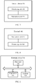
- FIG. 3 is a schematic block diagram of a network device 300 according to an embodiment of this application. As shown in FIG. 3 , the network device 300 includes a processing unit 310 and a transceiver unit 320.
- the processing unit 310 is configured to determine downlink control information DCI, wherein the DCI includes a first request field, information in the first request field is only used to instruct to send a first reference signal on a first resource, or the information in the first request field is used to instruct to send the first reference signal on the first resource and instruct a terminal to report a measurement result of the first reference signal on the first resource, and the measurement result includes channel state information CSI and/or beam state information BSI.
- the transceiver unit 320 is configured to send the DCI to the terminal.
- the units in the network device 300 are respectively configured to perform actions or processing processes performed by the network device in the foregoing methods, and therefore the beneficial effects of the method embodiments can also be achieved. To avoid repeated description, detailed description is omitted herein.
- FIG. 4 is a schematic block diagram of a terminal 400 according to an embodiment of this application. As shown in FIG. 4 , the terminal 400 includes a transceiver unit 410 and a processing unit 420.
- the transceiver unit 410 is configured to receive downlink control information DCI sent by a network device, wherein the DCI includes a first request field, information in the first request field is only used to instruct to send a first reference signal on a first resource, or the information in the first request field is used to instruct to send the first reference signal on the first resource and instruct the terminal to report a measurement result of the first reference signal on the first resource, and the measurement result includes channel state information CSI and/or beam state information BSI.
- the processing unit 420 is configured to determine, based on the DCI, whether to report the measurement result.
- the units in the terminal 400 are respectively configured to perform actions or processing processes performed by the terminal in the foregoing methods, and therefore can also achieve the beneficial effects of the method embodiments. To avoid repeated description, detailed description is omitted herein.
- FIG. 5 is a schematic structural diagram of a network device 500 according to an embodiment of this application.
- the network device 500 includes a transceiver 510, a processor 520, and a memory 530.
- the transceiver 510, the processor 520, and the memory 530 communicate with each other and transfer control and/or digital signals by using an internal connection channel.
- the processor 520 is configured to determine downlink control information DCI, wherein the DCI includes a first request field, information in the first request field is only used to instruct to send a first reference signal on a first resource, or the information in the first request field is used to instruct to send the first reference signal on the first resource and instruct a terminal to report a measurement result of the first reference signal on the first resource, and the measurement result includes channel state information CSI and/or beam state information BSI.
- the transceiver 510 is configured to send the DCI to the terminal.
- the processor 520 when the processor 520 invokes a computer program from the memory and executes the computer program, the processor 520 may be configured to: perform a data processing function of the network device in the foregoing method embodiments, and control the transceiver 510 to complete corresponding information sending and receiving functions of the network device.
- FIG. 6 is a schematic structural diagram of a terminal 600 according to an embodiment of this application.
- the terminal 600 includes a transceiver 610, a processor 620, and a memory 630.
- the transceiver 610, the processor 620, and the memory 630 communicate with each other and transfer control and/or digital signals by using an internal connection channel.
- the transceiver 610 is configured to receive downlink control information DCI sent by a network device, wherein the DCI includes a first request field, information in the first request field is only used to instruct to send a first reference signal on a first resource, or the information in the first request field is used to instruct to send the first reference signal on the first resource and instruct the terminal to report a measurement result of the first reference signal on the first resource, and the measurement result includes channel state information CSI and/or beam state information BSI.
- the processor 620 is configured to determine, based on the DCI, whether to report the measurement result.
- the processor 620 when the processor 620 invokes the computer program from the memory and executes the computer program, the processor 620 may be configured to: perform a data processing function of the terminal in the foregoing method embodiments, and control the transceiver 610 to complete corresponding information sending and receiving functions of the terminal.
- the embodiments of this application may be applied to a processor, or may be implemented by a processor.
- the processor may be an integrated circuit chip and has a signal processing capability. In an implementation process, steps in the foregoing method embodiments may be implemented by using a hardware integrated logical circuit in the processor, or by using instructions in a form of software.
- the processor may be a central processing unit (central processing unit, CPU).
- the processor may be another general purpose processor, digital signal processor (digital signal processor, DSP), application-specific integrated circuit (application-specific integrated circuit, ASIC), field programmable gate array (field programmable gate array, FPGA), another programmable logic device, discrete gate or transistor logic device, or a discrete hardware component.
- the processor can implement or perform the methods, steps, and logical block diagrams that are disclosed in the embodiments of this application.
- the general purpose processor may be a microprocessor, or the processor may be any conventional processor or the like.
- the steps of the methods disclosed with reference to the embodiments of this application may be directly embodied as being executed by a hardware decoding processor, or executed by a combination of hardware of a decoding processor and a software component.
- the software component may be located in a mature storage medium in the art, such as a random access memory, a flash memory, a read-only memory, a programmable read-only memory, an electrically erasable programmable memory, or a register.
- the storage medium is located in the memory, and the processor reads information in the memory and completes the steps in the foregoing methods in combination with hardware of the processor.
- the network device chip implements the function of the processing unit 310 or the processor 520.
- the network device chip sends the DCI to another module (for example, a radio frequency module or an antenna) in the network device.
- the DCI is sent to the terminal by the another module in the network device.
- the network device chip may further receive the measurement report from the another module (for example, the frequency module or the antenna) in the network device, and the measurement report is sent by the terminal to the network device.
- the terminal chip implements the function of the processing unit 420 or the processor 620.
- the terminal chip receives the DCI from another module (for example, a radio frequency module or an antenna) in the terminal, and the DCI is sent by the network device to the terminal.
- the terminal chip may further send the measurement report to the another module (for example, the frequency module or the antenna) in the terminal, and the measurement report is sent by the another module in the terminal to the network device.
- the memory in the embodiments of this application may be a volatile memory or a nonvolatile memory, or may include both a volatile memory and a nonvolatile memory.
- the nonvolatile memory may be a read-only memory (read-only memory, ROM), a programmable read-only memory (programmable ROM, PROM), an erasable programmable read-only memory (erasable PROM, EPROM), an electrically erasable programmable read-only memory (electrically EPROM, EEPROM), or a flash memory.
- the volatile memory may be a random access memory (random access memory, RAM), used as an external cache.
- RAMs for example, a static random access memory (static RAM, SRAM), a dynamic random access memory (dynamic RAM, DRAM), a synchronous dynamic random access memory (synchronous DRAM, SDRAM), a double data rate synchronous dynamic random access memory (double data rate SDRAM, DDR SDRAM), an enhanced synchronous dynamic random access memory (enhanced SDRAM, ESDRAM), a synchronous-link dynamic random access memory (synchlink DRAM, SLDRAM), and a direct rambus random access memory (direct rambus RAM, DRRAM), may be used.
- static random access memory static random access memory
- DRAM dynamic random access memory
- DRAM dynamic random access memory
- SDRAM synchronous dynamic random access memory
- double data rate SDRAM double data rate SDRAM
- DDR SDRAM double data rate SDRAM
- ESDRAM enhanced synchronous dynamic random access memory
- SLDRAM synchronous-link dynamic random access memory
- direct rambus RAM direct rambus RAM
- Embodiment 1 A transmission method, comprising:
- Embodiment 2 The method according to embodiment 1, wherein a format of the DCI is a first format, and the DCI satisfying the first format is used for downlink data transmission; and the information in the first request field is only used to instruct to send the first reference signal.
- Embodiment 3 The method according to embodiment 1 or 2, wherein the format of the DCI is a second format, and the DCI satisfying the second format is used for uplink data transmission; and the information in the first request field instructs to send the first reference signal and instructs the terminal to report the measurement result of the first reference signal.
- Embodiment 4 The method according to any one of embodiments 1 to 3, wherein:
- Embodiment 5 The method according to embodiment 4, wherein the first request field occupies ⁇ log 2 ( T ) ⁇ bits, a value of T is any one of S, S+1, SN , and SN+1, and ⁇ ⁇ represents rounding up.
- Embodiment 6 The method according to any one of embodiments 1 to 5, wherein the method further comprises: sending, by the network device, power information to the terminal, wherein the power information is used by the terminal to determine transmit power of the first reference signal.
- Embodiment 7 The method according to embodiment 6, wherein the power information is used to indicate a power ratio of the first reference signal to a second reference signal.
- Embodiment 9 A transmission method, comprising:
- Embodiment 10 The method according to embodiment 9, wherein a format of the DCI is a first format, and the DCI satisfying the first format is used for downlink data transmission; and the information in the first request field is only used to instruct to send the first reference signal.
- Embodiment 11 The method according to embodiment 9 or 10, wherein the format of the DCI is a second format, and the DCI satisfying the second format is used for uplink data transmission; and the information in the first request field instructs to send the first reference signal and instructs the terminal to report the measurement result of the first reference signal.
- Embodiment 12 The method according to any one of embodiments 9 to 11, wherein:
- Embodiment 13 The method according to embodiment 12, wherein the first request field occupies ⁇ log 2 ( T ) ⁇ bits, a value of T is any one of S, S+1, SN , and SN+1, and ⁇ ⁇ represents rounding up.
- Embodiment 14 The method according to any one of embodiments 9 to 13, wherein the method further comprises:
- Embodiment 15 The method according to embodiment 14, wherein the power information is used to indicate a power ratio of the first reference signal to a second reference signal.
- Embodiment 17 A network device, comprising:
- Embodiment 18 The network device according to embodiment 17, wherein a format of the DCI is a first format, and the DCI satisfying the first format is used for downlink data transmission; and the information in the first request field is only used to instruct to send the first reference signal.
- Embodiment 19 The network device according to embodiment 17 or 18, wherein the format of the DCI is a second format, and the DCI satisfying the second format is used for uplink data transmission; and the information in the first request field instructs to send the first reference signal and instructs the terminal to report the measurement result of the first reference signal.
- Embodiment 20 The network device according to any one of embodiments 17 to 19, wherein:
- Embodiment 21 The network device according to embodiment 20, wherein the first request field occupies ⁇ log 2 ( T ) ⁇ bits, a value of T is any one of S, S+1, SN , and SN+1, and ⁇ ⁇ represents rounding up.
- Embodiment 22 The network device according to any one of embodiments 17 to 21, wherein the transceiver unit is further configured to: send power information to the terminal, wherein the power information is used by the terminal to determine transmit power of the first reference signal.
- Embodiment 23 The network device according to embodiment 22, wherein the power information is used to indicate a power ratio of the first reference signal to a second reference signal.
- a terminal comprising:
- Embodiment 25 The terminal according to embodiment 24, wherein a format of the DCI is a first format, and the DCI satisfying the first format is used for downlink data transmission; and the information in the first request field is only used to instruct to send the first reference signal
- Embodiment 26 The terminal according to embodiment 24 or 25, wherein the format of the DCI is a second format, and the DCI satisfying the second format is used for uplink data transmission; and the information in the first request field instructs to send the first reference signal and instructs the terminal to report the measurement result of the first reference signal.
- Embodiment 27 The terminal according to any one of embodiments 24 to 26, wherein:
- Embodiment 28 The terminal according to embodiment 27, wherein the first request field occupies ⁇ log 2 ( T ) ⁇ bits, a value of T is any one of S, S+1, SN , and SN +1, and ⁇ ⁇ represents rounding up.
- Embodiment 29 The terminal according to any one of embodiments 24 to 28, wherein the transceiver unit is further configured to receive power information sent by the network device; and the processing unit is further configured to determine transmit power of the first reference signal based on the power information.
- Embodiment 30 The terminal according to embodiment 29, wherein the power information is used to indicate a power ratio of the first reference signal to a second reference signal.
- a network device comprising:
- Embodiment 32 The network device according to embodiment 31, wherein a format of the DCI is a first format, and the DCI satisfying the first format is used for downlink data transmission; and the information in the first request field is only used to instruct to send the first reference signal.
- Embodiment 33 The network device according to embodiment 31 or 32, wherein the format of the DCI is a second format, and the DCI satisfying the second format is used for uplink data transmission; and the information in the first request field instructs to send the first reference signal and instructs the terminal to report the measurement result of the first reference signal.
- Embodiment 34 The network device according to any one of embodiments 31 to 33, wherein:
- Embodiment 35 The network device according to embodiment 34, wherein the first request field occupies ⁇ log 2 ( T ) ⁇ bits, a value of T is any one of S, S+1, SN , and SN +1, and ⁇ ⁇ represents rounding up.
- Embodiment 36 The network device according to any one of embodiments 31 to 35, wherein the transceiver is further configured to: send power information to the terminal, wherein the power information is used by the terminal to determine transmit power of the first reference signal.
- Embodiment 37 The network device according to embodiment 36, wherein the power information is used to indicate a power ratio of the first reference signal to a second reference signal.
- a terminal comprising:
- Embodiment 39 The terminal according to embodiment 38, wherein a format of the DCI is a first format, and the DCI satisfying the first format is used for downlink data transmission; and the information in the first request field is only used to instruct to send the first reference signal.
- Embodiment 40 The terminal according to embodiment 38 or 39, wherein the format of the DCI is a second format, and the DCI satisfying the second format is used for uplink data transmission; and the information in the first request field instructs to send the first reference signal and instructs the terminal to report the measurement result of the first reference signal
- Embodiment 41 The terminal according to any one of embodiments 38 to 40, wherein:
- Embodiment 42 The terminal according to embodiment 41, wherein the first request field occupies ⁇ log 2 ( T ) ⁇ bits, a value of T is any one of S, S+1, SN , and SN +1, and ⁇ ⁇ represents rounding up.
- Embodiment 43 The terminal according to any one of embodiments 38 to 42, wherein the transceiver unit is further configured to receive power information sent by the network device; and the processing unit is further configured to determine transmit power of the first reference signal based on the power information.
- Embodiment 44 The terminal according to embodiment 43, wherein the power information is used to indicate a power ratio of the first reference signal to a second reference signal.
- Embodiment 45 A chip system, comprising: a processor, configured to invoke a computer program from a memory and execute the computer program, so that a device on which the chip system is installed performs the method according to any one of embodiments 1 to 16.
- Embodiment 46 A computer readable storage medium, comprising a computer program, wherein when the computer program runs on a computer, the computer is enabled to perform the method according to any one of embodiments 1 to 16.
- Embodiment 47 A computer program product, wherein the computer program product comprises a computer program, and when the computer program runs on a computer, the computer is enabled to perform the method according to any one of embodiments 1 to 16.
- Embodiment 48 A communications system, comprising:
- sequence numbers of the foregoing processes do not mean execution sequences in the embodiments of this application.
- the execution sequences of the processes should be determined according to functions and internal logic of the processes, and should not be construed as any limitation on the implementation processes of the embodiments of this application.
- the disclosed apparatus and method may be implemented in other manners.
- the described apparatus embodiment is merely an example.
- the unit division is merely logical function division and may be other division in actual implementation.
- a plurality of units or components may be combined or integrated into another system, or some features may be ignored or not performed.
- the displayed or discussed mutual couplings or direct couplings or communication connections may be implemented by using some interfaces.
- the indirect couplings or communication connections between the apparatuses or units may be implemented in electronic, mechanical, or other forms.
- the units described as separate parts may or may not be physically separate, and parts displayed as units may or may not be physical units, that is, may be located in one position, or may be distributed on a plurality of network units. Some or all of the units may be selected based on actual requirements to achieve the objectives of the solutions of the embodiments.
- the functions When the functions are implemented in a form of a software functional unit and sold or used as an independent product, the functions may be stored in a computer-readable storage medium. Based on such an understanding, the technical solutions of this application essentially, or the part contributing to the prior art, or some of the technical solutions may be implemented in a form of a software product.
- the software product is stored in a storage medium, and includes several instructions for instructing a computer device (which may be a personal computer, a server, a network device, or the like) to perform all or some of the steps of the methods described in the embodiments of this application.
- the foregoing storage medium includes: any medium that can store program code, such as a USB flash drive, a removable hard disk, a read-only memory (read-only memory, ROM), a random access memory (random access memory, RAM), a magnetic disk, or an optical disc.
- program code such as a USB flash drive, a removable hard disk, a read-only memory (read-only memory, ROM), a random access memory (random access memory, RAM), a magnetic disk, or an optical disc.
Landscapes
- Engineering & Computer Science (AREA)
- Signal Processing (AREA)
- Computer Networks & Wireless Communication (AREA)
- Physics & Mathematics (AREA)
- Mathematical Physics (AREA)
- Quality & Reliability (AREA)
- Mobile Radio Communication Systems (AREA)
- Radio Relay Systems (AREA)
Priority Applications (1)
| Application Number | Priority Date | Filing Date | Title |
|---|---|---|---|
| EP23199596.0A EP4366215A3 (fr) | 2017-06-16 | 2018-06-15 | Procédé de transmission, dispositif de réseau et terminal |
Applications Claiming Priority (3)
| Application Number | Priority Date | Filing Date | Title |
|---|---|---|---|
| CN201710459498.1A CN109151885B (zh) | 2017-06-16 | 2017-06-16 | 传输方法、网络设备和终端 |
| PCT/CN2018/091508 WO2018228535A1 (fr) | 2017-06-16 | 2018-06-15 | Procédé de transmission, dispositif de réseau, et terminal |
| EP18817412.2A EP3562201B1 (fr) | 2017-06-16 | 2018-06-15 | Procédé de transmission, dispositif de réseau, et terminal |
Related Parent Applications (1)
| Application Number | Title | Priority Date | Filing Date |
|---|---|---|---|
| EP18817412.2A Division EP3562201B1 (fr) | 2017-06-16 | 2018-06-15 | Procédé de transmission, dispositif de réseau, et terminal |
Related Child Applications (1)
| Application Number | Title | Priority Date | Filing Date |
|---|---|---|---|
| EP23199596.0A Division EP4366215A3 (fr) | 2017-06-16 | 2018-06-15 | Procédé de transmission, dispositif de réseau et terminal |
Publications (2)
| Publication Number | Publication Date |
|---|---|
| EP4075683A1 true EP4075683A1 (fr) | 2022-10-19 |
| EP4075683B1 EP4075683B1 (fr) | 2023-10-18 |
Family
ID=64659680
Family Applications (3)
| Application Number | Title | Priority Date | Filing Date |
|---|---|---|---|
| EP22160664.3A Active EP4075683B1 (fr) | 2017-06-16 | 2018-06-15 | Procédé de transmission |
| EP23199596.0A Pending EP4366215A3 (fr) | 2017-06-16 | 2018-06-15 | Procédé de transmission, dispositif de réseau et terminal |
| EP18817412.2A Active EP3562201B1 (fr) | 2017-06-16 | 2018-06-15 | Procédé de transmission, dispositif de réseau, et terminal |
Family Applications After (2)
| Application Number | Title | Priority Date | Filing Date |
|---|---|---|---|
| EP23199596.0A Pending EP4366215A3 (fr) | 2017-06-16 | 2018-06-15 | Procédé de transmission, dispositif de réseau et terminal |
| EP18817412.2A Active EP3562201B1 (fr) | 2017-06-16 | 2018-06-15 | Procédé de transmission, dispositif de réseau, et terminal |
Country Status (8)
| Country | Link |
|---|---|
| US (2) | US11184887B2 (fr) |
| EP (3) | EP4075683B1 (fr) |
| JP (1) | JP6972142B2 (fr) |
| CN (4) | CN110446226B (fr) |
| BR (1) | BR112019012989A2 (fr) |
| CA (1) | CA3047498C (fr) |
| ES (1) | ES2910053T3 (fr) |
| WO (1) | WO2018228535A1 (fr) |
Families Citing this family (19)
| Publication number | Priority date | Publication date | Assignee | Title |
|---|---|---|---|---|
| WO2018010184A1 (fr) * | 2016-07-15 | 2018-01-18 | 广东欧珀移动通信有限公司 | Procédé de communication basé sur un réseau sans fil, dispositif terminal, et dispositif de réseau |
| US11057091B2 (en) * | 2018-02-16 | 2021-07-06 | Qualcomm Incorporated | Reference signals for tracking |
| CN114567928B (zh) * | 2019-02-15 | 2024-03-26 | 成都华为技术有限公司 | 用于定位终端设备的方法和装置 |
| CN111586855B (zh) * | 2019-02-15 | 2024-02-09 | 华为技术有限公司 | 信号传输的方法与装置 |
| CN112997525A (zh) | 2019-02-15 | 2021-06-18 | Oppo广东移动通信有限公司 | 无线通信方法、终端设备和网络设备 |
| CN111934829B (zh) | 2019-05-12 | 2024-04-12 | 华为技术有限公司 | 传输信号的方法、终端设备和网络设备 |
| WO2020237424A1 (fr) * | 2019-05-24 | 2020-12-03 | 北京小米移动软件有限公司 | Procédé et appareil de communication basés sur un spectre sans licence, et support de stockage |
| WO2021056566A1 (fr) * | 2019-09-29 | 2021-04-01 | 华为技术有限公司 | Procédé et appareil d'envoi de résultat de mesure d'angle |
| CN112788654B (zh) | 2019-11-08 | 2023-04-14 | 大唐移动通信设备有限公司 | 信息上报方法、终端及基站 |
| CN117354904A (zh) * | 2020-01-10 | 2024-01-05 | 华为技术有限公司 | 通信方法及装置 |
| CN115066925B (zh) * | 2020-04-01 | 2025-02-28 | 华为技术有限公司 | 终端定位方法及装置 |
| CN113766645B (zh) * | 2020-06-03 | 2024-11-19 | 华为技术有限公司 | 资源信息的传输方法及装置 |
| WO2022073492A1 (fr) * | 2020-10-10 | 2022-04-14 | 上海朗帛通信技术有限公司 | Procédé et dispositif utilisés dans un nœud pour une communication sans fil |
| CN114501546B (zh) * | 2020-10-26 | 2024-11-26 | 大唐移动通信设备有限公司 | 一种定位测量方法和装置及设备 |
| CN115442007A (zh) * | 2021-06-04 | 2022-12-06 | 维沃移动通信有限公司 | 一种信号传输方法、装置、设备及系统 |
| CN115884249A (zh) * | 2021-09-29 | 2023-03-31 | 华为技术有限公司 | 一种通信方法及通信装置 |
| CN121359560A (zh) * | 2023-10-26 | 2026-01-16 | 北京小米移动软件有限公司 | 信道测量信息确定方法、终端、网络设备 |
| CN121142584A (zh) * | 2024-06-14 | 2025-12-16 | 华为技术有限公司 | 一种测量及上报方法及装置 |
| WO2026055944A1 (fr) * | 2024-09-13 | 2026-03-19 | Nec Corporation | Procédé, dispositif et support de stockage informatique de communication |
Citations (1)
| Publication number | Priority date | Publication date | Assignee | Title |
|---|---|---|---|---|
| US20170026938A1 (en) * | 2015-07-21 | 2017-01-26 | Samsung Electronics Co., Ltd | Method and apparatus for beam-level radio resource management and mobility in cellular network |
Family Cites Families (26)
| Publication number | Priority date | Publication date | Assignee | Title |
|---|---|---|---|---|
| CN103004116B (zh) * | 2010-07-16 | 2017-04-12 | Lg电子株式会社 | 发送控制信息的方法和设备 |
| WO2012092720A1 (fr) * | 2011-01-07 | 2012-07-12 | 富士通株式会社 | Procédé d'envoi de signal de référence de sondage, nœud b évolué et équipement utilisateur |
| EP2763471B1 (fr) * | 2011-09-30 | 2018-07-04 | Sharp Kabushiki Kaisha | Terminal et procédé de communication |
| CN103220076B (zh) * | 2012-01-21 | 2016-12-07 | 华为技术有限公司 | 通信方法、设备及系统 |
| CN104081827B (zh) * | 2012-01-27 | 2018-04-13 | 三星电子株式会社 | 用于非周期性的信道状态信息的多个过程的报告 |
| US9198071B2 (en) | 2012-03-19 | 2015-11-24 | Qualcomm Incorporated | Channel state information reference signal configuring and reporting for a coordinated multi-point transmission scheme |
| JP2013236288A (ja) * | 2012-05-10 | 2013-11-21 | Sharp Corp | 端末、通信方法および集積回路 |
| US9178583B2 (en) * | 2013-01-08 | 2015-11-03 | Samsung Electronics Co., Ltd. | Channel state information feedback design in advanced wireless communication systems |
| JP6161347B2 (ja) * | 2013-03-19 | 2017-07-12 | 株式会社Nttドコモ | ユーザ端末、無線基地局及び無線通信方法 |
| CN104244319A (zh) * | 2013-06-20 | 2014-12-24 | 北京三星通信技术研究有限公司 | 测量并上报csi的方法及设备 |
| WO2015005462A1 (fr) * | 2013-07-12 | 2015-01-15 | シャープ株式会社 | Dispositif de terminal, procédé et circuit intégré |
| US20150089382A1 (en) * | 2013-09-26 | 2015-03-26 | Wu-chi Feng | Application context migration framework and protocol |
| CN106537964B (zh) | 2014-01-31 | 2020-01-03 | 华为技术有限公司 | 用于网络适配和利用下行链路发现参考信号的设备、网络和方法 |
| US9743392B2 (en) * | 2015-01-30 | 2017-08-22 | Motorola Mobility Llc | Method and apparatus for signaling aperiodic channel state indication reference signals for LTE operation |
| CN106301692B (zh) | 2015-05-21 | 2019-12-10 | 电信科学技术研究院 | 一种信道状态信息获取方法及装置 |
| BR112017023357A2 (pt) * | 2015-05-22 | 2018-07-17 | Fujitsu Limited | método e aparelho de configuração de recurso de sinal de referência e sistema de comunicação |
| CN114024805B (zh) * | 2015-07-20 | 2024-05-21 | 北京三星通信技术研究有限公司 | 一种多用户数据传输方法和设备 |
| CN106375044A (zh) * | 2015-07-23 | 2017-02-01 | 中兴通讯股份有限公司 | 非授权载波的信道状态信息测量反馈方法、基站、终端 |
| JP2017050758A (ja) * | 2015-09-03 | 2017-03-09 | ソニー株式会社 | 端末装置及び無線通信装置 |
| CN106559109A (zh) | 2015-09-25 | 2017-04-05 | 中兴通讯股份有限公司 | 一种信道状态信息测量反馈方法和装置 |
| EP3379747A4 (fr) * | 2015-11-17 | 2018-11-14 | Sony Corporation | Dispositif terminal, dispositif de communication par radio et procédé de communication |
| CN106792786A (zh) * | 2015-11-24 | 2017-05-31 | 中国移动通信集团公司 | 一种邻频测量方法、基站及终端 |
| JP2017184000A (ja) * | 2016-03-30 | 2017-10-05 | ソニー株式会社 | 通信装置、通信方法及びプログラム |
| US11171746B2 (en) * | 2016-06-15 | 2021-11-09 | Apple Inc. | Channel state and beam related information reporting |
| US10505618B2 (en) * | 2016-08-10 | 2019-12-10 | Samsung Electronics Co., Ltd. | Method and apparatus for beam measurement and management in wireless systems |
| US10944450B2 (en) * | 2017-01-06 | 2021-03-09 | Lg Electronics Inc. | Method for receiving reference signal in wireless communication system and apparatus therefor |
-
2017
- 2017-06-16 CN CN201910249952.XA patent/CN110446226B/zh active Active
- 2017-06-16 CN CN201910259525.XA patent/CN109905224B/zh active Active
- 2017-06-16 CN CN201710459498.1A patent/CN109151885B/zh active Active
-
2018
- 2018-06-15 BR BR112019012989A patent/BR112019012989A2/pt unknown
- 2018-06-15 CA CA3047498A patent/CA3047498C/fr active Active
- 2018-06-15 EP EP22160664.3A patent/EP4075683B1/fr active Active
- 2018-06-15 EP EP23199596.0A patent/EP4366215A3/fr active Pending
- 2018-06-15 CN CN201880039860.2A patent/CN110754108B/zh active Active
- 2018-06-15 WO PCT/CN2018/091508 patent/WO2018228535A1/fr not_active Ceased
- 2018-06-15 EP EP18817412.2A patent/EP3562201B1/fr active Active
- 2018-06-15 JP JP2019540581A patent/JP6972142B2/ja active Active
- 2018-06-15 ES ES18817412T patent/ES2910053T3/es active Active
-
2019
- 2019-06-14 US US16/441,938 patent/US11184887B2/en active Active
-
2021
- 2021-11-05 US US17/520,416 patent/US11778633B2/en active Active
Patent Citations (1)
| Publication number | Priority date | Publication date | Assignee | Title |
|---|---|---|---|---|
| US20170026938A1 (en) * | 2015-07-21 | 2017-01-26 | Samsung Electronics Co., Ltd | Method and apparatus for beam-level radio resource management and mobility in cellular network |
Non-Patent Citations (4)
| Title |
|---|
| CATT: "CSI feedback for beamformed CSI-RS on PUSCH", vol. RAN WG1, no. Beijing, China; 20150824 - 20150828, 15 August 2015 (2015-08-15), XP050993048, Retrieved from the Internet <URL:http://www.3gpp.org/ftp/tsg_ran/WG1_RL1/TSGR1_82/Docs/> [retrieved on 20150815] * |
| HUAWEI ET AL: "Independent and joint control of CSI-RS transmission and CSI reporting for NR MIMO", vol. RAN WG1, no. Athens, Greece; 20170213 - 20170217, 6 February 2017 (2017-02-06), XP051220556, Retrieved from the Internet <URL:http://www.3gpp.org/ftp/tsg_ran/WG1_RL1/TSGR1_88/Docs/> [retrieved on 20170206] * |
| QUALCOMM INCORPORATED: "Remaining details on aperiodic CSI-RS", vol. RAN WG1, no. Lisbon, Portugal; 20161010 - 20161014, 9 October 2016 (2016-10-09), XP051149997, Retrieved from the Internet <URL:http://www.3gpp.org/ftp/Meetings_3GPP_SYNC/RAN1/Docs/> [retrieved on 20161009] * |
| TEXAS INSTRUMENTS: "CQI reference resource with CSI-RS", 3GPP DRAFT; R1-110260 TI CQI REFERENCE RESOURCE WITH CSI-RS_V5, 3RD GENERATION PARTNERSHIP PROJECT (3GPP), MOBILE COMPETENCE CENTRE ; 650, ROUTE DES LUCIOLES ; F-06921 SOPHIA-ANTIPOLIS CEDEX ; FRANCE, vol. RAN WG1, no. Dublin, Ireland; 20110117 - 20110121, 31 January 2011 (2011-01-31), XP050599030 * |
Also Published As
| Publication number | Publication date |
|---|---|
| WO2018228535A1 (fr) | 2018-12-20 |
| BR112019012989A2 (pt) | 2019-12-03 |
| CA3047498C (fr) | 2023-10-03 |
| JP6972142B2 (ja) | 2021-11-24 |
| CA3047498A1 (fr) | 2018-12-20 |
| ES2910053T3 (es) | 2022-05-11 |
| JP2020507970A (ja) | 2020-03-12 |
| CN110446226A (zh) | 2019-11-12 |
| EP3562201A1 (fr) | 2019-10-30 |
| US20190327719A1 (en) | 2019-10-24 |
| CN109905224B (zh) | 2020-06-26 |
| EP3562201A4 (fr) | 2020-02-26 |
| EP4075683B1 (fr) | 2023-10-18 |
| EP4366215A2 (fr) | 2024-05-08 |
| CN109905224A (zh) | 2019-06-18 |
| CN109151885B (zh) | 2023-11-10 |
| US20220061038A1 (en) | 2022-02-24 |
| CN110754108A (zh) | 2020-02-04 |
| EP3562201B1 (fr) | 2022-03-09 |
| CN109151885A (zh) | 2019-01-04 |
| US11184887B2 (en) | 2021-11-23 |
| CN110446226B (zh) | 2021-03-23 |
| EP4366215A3 (fr) | 2024-06-19 |
| US11778633B2 (en) | 2023-10-03 |
| CN110754108B (zh) | 2021-11-30 |
Similar Documents
| Publication | Publication Date | Title |
|---|---|---|
| US11778633B2 (en) | Transmission method, network device, and terminal | |
| US10785010B2 (en) | Wireless communications method and apparatus | |
| US20220231745A1 (en) | Wireless Communication Method, Network Device, and Terminal Device | |
| JP7287494B2 (ja) | 信号送受信方法、装置及びシステム | |
| EP3860028A1 (fr) | Procédé de communication sans fil et appareil de communications sans fil | |
| EP3429281B1 (fr) | Procédé et dispositif de commande de puissance | |
| US20190238210A1 (en) | Beam Tracking Method, Terminal Device, and Network-Side Device | |
| EP3116155A1 (fr) | Procédé et équipement pour rapport csi | |
| KR20200013041A (ko) | 채널 품질 피드백 방법 및 장치 | |
| EP3965493A1 (fr) | Procédé de rapport de csi et dispositif terminal | |
| US11470635B2 (en) | Communication method and device | |
| WO2022067823A1 (fr) | Procédé et dispositif de commande de puissance de liaison montante | |
| EP3694279A1 (fr) | Procédé et dispositif de communication | |
| EP3531753A1 (fr) | Procédé de contrôle de puissance de liaison montante et appareil de communication | |
| EP4708983A1 (fr) | Procédé, dispositif et système de communications | |
| US9467956B2 (en) | Method for indication of reference symbol transmission power change in cellular network | |
| US20250062874A1 (en) | Signal transmitting and receiving apparatus and method | |
| EP4665013A1 (fr) | Procédé de rapport de réserve de puissance, appareil de communication, terminal et dispositif réseau |
Legal Events
| Date | Code | Title | Description |
|---|---|---|---|
| PUAI | Public reference made under article 153(3) epc to a published international application that has entered the european phase |
Free format text: ORIGINAL CODE: 0009012 |
|
| STAA | Information on the status of an ep patent application or granted ep patent |
Free format text: STATUS: REQUEST FOR EXAMINATION WAS MADE |
|
| 17P | Request for examination filed |
Effective date: 20220308 |
|
| AC | Divisional application: reference to earlier application |
Ref document number: 3562201 Country of ref document: EP Kind code of ref document: P |
|
| AK | Designated contracting states |
Kind code of ref document: A1 Designated state(s): AL AT BE BG CH CY CZ DE DK EE ES FI FR GB GR HR HU IE IS IT LI LT LU LV MC MK MT NL NO PL PT RO RS SE SI SK SM TR |
|
| RIC1 | Information provided on ipc code assigned before grant |
Ipc: H04W 72/04 20090101ALN20230328BHEP Ipc: H04W 24/10 20090101ALN20230328BHEP Ipc: H04L 5/00 20060101ALI20230328BHEP Ipc: H04B 7/06 20060101AFI20230328BHEP |
|
| GRAP | Despatch of communication of intention to grant a patent |
Free format text: ORIGINAL CODE: EPIDOSNIGR1 |
|
| STAA | Information on the status of an ep patent application or granted ep patent |
Free format text: STATUS: GRANT OF PATENT IS INTENDED |
|
| INTG | Intention to grant announced |
Effective date: 20230510 |
|
| GRAS | Grant fee paid |
Free format text: ORIGINAL CODE: EPIDOSNIGR3 |
|
| GRAA | (expected) grant |
Free format text: ORIGINAL CODE: 0009210 |
|
| STAA | Information on the status of an ep patent application or granted ep patent |
Free format text: STATUS: THE PATENT HAS BEEN GRANTED |
|
| AC | Divisional application: reference to earlier application |
Ref document number: 3562201 Country of ref document: EP Kind code of ref document: P |
|
| AK | Designated contracting states |
Kind code of ref document: B1 Designated state(s): AL AT BE BG CH CY CZ DE DK EE ES FI FR GB GR HR HU IE IS IT LI LT LU LV MC MK MT NL NO PL PT RO RS SE SI SK SM TR |
|
| REG | Reference to a national code |
Ref country code: GB Ref legal event code: FG4D |
|
| REG | Reference to a national code |
Ref country code: CH Ref legal event code: EP |
|
| REG | Reference to a national code |
Ref country code: DE Ref legal event code: R096 Ref document number: 602018059813 Country of ref document: DE |
|
| REG | Reference to a national code |
Ref country code: IE Ref legal event code: FG4D |
|
| REG | Reference to a national code |
Ref country code: LT Ref legal event code: MG9D |
|
| REG | Reference to a national code |
Ref country code: NL Ref legal event code: MP Effective date: 20231018 |
|
| REG | Reference to a national code |
Ref country code: AT Ref legal event code: MK05 Ref document number: 1623397 Country of ref document: AT Kind code of ref document: T Effective date: 20231018 |
|
| PG25 | Lapsed in a contracting state [announced via postgrant information from national office to epo] |
Ref country code: NL Free format text: LAPSE BECAUSE OF FAILURE TO SUBMIT A TRANSLATION OF THE DESCRIPTION OR TO PAY THE FEE WITHIN THE PRESCRIBED TIME-LIMIT Effective date: 20231018 |
|
| PG25 | Lapsed in a contracting state [announced via postgrant information from national office to epo] |
Ref country code: GR Free format text: LAPSE BECAUSE OF FAILURE TO SUBMIT A TRANSLATION OF THE DESCRIPTION OR TO PAY THE FEE WITHIN THE PRESCRIBED TIME-LIMIT Effective date: 20240119 |
|
| PG25 | Lapsed in a contracting state [announced via postgrant information from national office to epo] |
Ref country code: IS Free format text: LAPSE BECAUSE OF FAILURE TO SUBMIT A TRANSLATION OF THE DESCRIPTION OR TO PAY THE FEE WITHIN THE PRESCRIBED TIME-LIMIT Effective date: 20240218 |
|
| PG25 | Lapsed in a contracting state [announced via postgrant information from national office to epo] |
Ref country code: LT Free format text: LAPSE BECAUSE OF FAILURE TO SUBMIT A TRANSLATION OF THE DESCRIPTION OR TO PAY THE FEE WITHIN THE PRESCRIBED TIME-LIMIT Effective date: 20231018 |
|
| PG25 | Lapsed in a contracting state [announced via postgrant information from national office to epo] |
Ref country code: AT Free format text: LAPSE BECAUSE OF FAILURE TO SUBMIT A TRANSLATION OF THE DESCRIPTION OR TO PAY THE FEE WITHIN THE PRESCRIBED TIME-LIMIT Effective date: 20231018 |
|
| PG25 | Lapsed in a contracting state [announced via postgrant information from national office to epo] |
Ref country code: ES Free format text: LAPSE BECAUSE OF FAILURE TO SUBMIT A TRANSLATION OF THE DESCRIPTION OR TO PAY THE FEE WITHIN THE PRESCRIBED TIME-LIMIT Effective date: 20231018 |
|
| PG25 | Lapsed in a contracting state [announced via postgrant information from national office to epo] |
Ref country code: LT Free format text: LAPSE BECAUSE OF FAILURE TO SUBMIT A TRANSLATION OF THE DESCRIPTION OR TO PAY THE FEE WITHIN THE PRESCRIBED TIME-LIMIT Effective date: 20231018 Ref country code: IS Free format text: LAPSE BECAUSE OF FAILURE TO SUBMIT A TRANSLATION OF THE DESCRIPTION OR TO PAY THE FEE WITHIN THE PRESCRIBED TIME-LIMIT Effective date: 20240218 Ref country code: GR Free format text: LAPSE BECAUSE OF FAILURE TO SUBMIT A TRANSLATION OF THE DESCRIPTION OR TO PAY THE FEE WITHIN THE PRESCRIBED TIME-LIMIT Effective date: 20240119 Ref country code: ES Free format text: LAPSE BECAUSE OF FAILURE TO SUBMIT A TRANSLATION OF THE DESCRIPTION OR TO PAY THE FEE WITHIN THE PRESCRIBED TIME-LIMIT Effective date: 20231018 Ref country code: BG Free format text: LAPSE BECAUSE OF FAILURE TO SUBMIT A TRANSLATION OF THE DESCRIPTION OR TO PAY THE FEE WITHIN THE PRESCRIBED TIME-LIMIT Effective date: 20240118 Ref country code: AT Free format text: LAPSE BECAUSE OF FAILURE TO SUBMIT A TRANSLATION OF THE DESCRIPTION OR TO PAY THE FEE WITHIN THE PRESCRIBED TIME-LIMIT Effective date: 20231018 Ref country code: PT Free format text: LAPSE BECAUSE OF FAILURE TO SUBMIT A TRANSLATION OF THE DESCRIPTION OR TO PAY THE FEE WITHIN THE PRESCRIBED TIME-LIMIT Effective date: 20240219 |
|
| PG25 | Lapsed in a contracting state [announced via postgrant information from national office to epo] |
Ref country code: SE Free format text: LAPSE BECAUSE OF FAILURE TO SUBMIT A TRANSLATION OF THE DESCRIPTION OR TO PAY THE FEE WITHIN THE PRESCRIBED TIME-LIMIT Effective date: 20231018 Ref country code: RS Free format text: LAPSE BECAUSE OF FAILURE TO SUBMIT A TRANSLATION OF THE DESCRIPTION OR TO PAY THE FEE WITHIN THE PRESCRIBED TIME-LIMIT Effective date: 20231018 Ref country code: PL Free format text: LAPSE BECAUSE OF FAILURE TO SUBMIT A TRANSLATION OF THE DESCRIPTION OR TO PAY THE FEE WITHIN THE PRESCRIBED TIME-LIMIT Effective date: 20231018 Ref country code: NO Free format text: LAPSE BECAUSE OF FAILURE TO SUBMIT A TRANSLATION OF THE DESCRIPTION OR TO PAY THE FEE WITHIN THE PRESCRIBED TIME-LIMIT Effective date: 20240118 Ref country code: LV Free format text: LAPSE BECAUSE OF FAILURE TO SUBMIT A TRANSLATION OF THE DESCRIPTION OR TO PAY THE FEE WITHIN THE PRESCRIBED TIME-LIMIT Effective date: 20231018 Ref country code: HR Free format text: LAPSE BECAUSE OF FAILURE TO SUBMIT A TRANSLATION OF THE DESCRIPTION OR TO PAY THE FEE WITHIN THE PRESCRIBED TIME-LIMIT Effective date: 20231018 |
|
| PG25 | Lapsed in a contracting state [announced via postgrant information from national office to epo] |
Ref country code: DK Free format text: LAPSE BECAUSE OF FAILURE TO SUBMIT A TRANSLATION OF THE DESCRIPTION OR TO PAY THE FEE WITHIN THE PRESCRIBED TIME-LIMIT Effective date: 20231018 |
|
| REG | Reference to a national code |
Ref country code: DE Ref legal event code: R097 Ref document number: 602018059813 Country of ref document: DE |
|
| PG25 | Lapsed in a contracting state [announced via postgrant information from national office to epo] |
Ref country code: CZ Free format text: LAPSE BECAUSE OF FAILURE TO SUBMIT A TRANSLATION OF THE DESCRIPTION OR TO PAY THE FEE WITHIN THE PRESCRIBED TIME-LIMIT Effective date: 20231018 |
|
| PG25 | Lapsed in a contracting state [announced via postgrant information from national office to epo] |
Ref country code: SK Free format text: LAPSE BECAUSE OF FAILURE TO SUBMIT A TRANSLATION OF THE DESCRIPTION OR TO PAY THE FEE WITHIN THE PRESCRIBED TIME-LIMIT Effective date: 20231018 |
|
| PG25 | Lapsed in a contracting state [announced via postgrant information from national office to epo] |
Ref country code: SM Free format text: LAPSE BECAUSE OF FAILURE TO SUBMIT A TRANSLATION OF THE DESCRIPTION OR TO PAY THE FEE WITHIN THE PRESCRIBED TIME-LIMIT Effective date: 20231018 Ref country code: SK Free format text: LAPSE BECAUSE OF FAILURE TO SUBMIT A TRANSLATION OF THE DESCRIPTION OR TO PAY THE FEE WITHIN THE PRESCRIBED TIME-LIMIT Effective date: 20231018 Ref country code: RO Free format text: LAPSE BECAUSE OF FAILURE TO SUBMIT A TRANSLATION OF THE DESCRIPTION OR TO PAY THE FEE WITHIN THE PRESCRIBED TIME-LIMIT Effective date: 20231018 Ref country code: IT Free format text: LAPSE BECAUSE OF FAILURE TO SUBMIT A TRANSLATION OF THE DESCRIPTION OR TO PAY THE FEE WITHIN THE PRESCRIBED TIME-LIMIT Effective date: 20231018 Ref country code: EE Free format text: LAPSE BECAUSE OF FAILURE TO SUBMIT A TRANSLATION OF THE DESCRIPTION OR TO PAY THE FEE WITHIN THE PRESCRIBED TIME-LIMIT Effective date: 20231018 Ref country code: DK Free format text: LAPSE BECAUSE OF FAILURE TO SUBMIT A TRANSLATION OF THE DESCRIPTION OR TO PAY THE FEE WITHIN THE PRESCRIBED TIME-LIMIT Effective date: 20231018 Ref country code: CZ Free format text: LAPSE BECAUSE OF FAILURE TO SUBMIT A TRANSLATION OF THE DESCRIPTION OR TO PAY THE FEE WITHIN THE PRESCRIBED TIME-LIMIT Effective date: 20231018 |
|
| PLBE | No opposition filed within time limit |
Free format text: ORIGINAL CODE: 0009261 |
|
| STAA | Information on the status of an ep patent application or granted ep patent |
Free format text: STATUS: NO OPPOSITION FILED WITHIN TIME LIMIT |
|
| 26N | No opposition filed |
Effective date: 20240719 |
|
| PG25 | Lapsed in a contracting state [announced via postgrant information from national office to epo] |
Ref country code: SI Free format text: LAPSE BECAUSE OF FAILURE TO SUBMIT A TRANSLATION OF THE DESCRIPTION OR TO PAY THE FEE WITHIN THE PRESCRIBED TIME-LIMIT Effective date: 20231018 |
|
| PG25 | Lapsed in a contracting state [announced via postgrant information from national office to epo] |
Ref country code: SI Free format text: LAPSE BECAUSE OF FAILURE TO SUBMIT A TRANSLATION OF THE DESCRIPTION OR TO PAY THE FEE WITHIN THE PRESCRIBED TIME-LIMIT Effective date: 20231018 |
|
| PG25 | Lapsed in a contracting state [announced via postgrant information from national office to epo] |
Ref country code: MC Free format text: LAPSE BECAUSE OF FAILURE TO SUBMIT A TRANSLATION OF THE DESCRIPTION OR TO PAY THE FEE WITHIN THE PRESCRIBED TIME-LIMIT Effective date: 20231018 |
|
| REG | Reference to a national code |
Ref country code: CH Ref legal event code: PL |
|
| PG25 | Lapsed in a contracting state [announced via postgrant information from national office to epo] |
Ref country code: LU Free format text: LAPSE BECAUSE OF NON-PAYMENT OF DUE FEES Effective date: 20240615 |
|
| GBPC | Gb: european patent ceased through non-payment of renewal fee |
Effective date: 20240615 |
|
| PG25 | Lapsed in a contracting state [announced via postgrant information from national office to epo] |
Ref country code: BE Free format text: LAPSE BECAUSE OF NON-PAYMENT OF DUE FEES Effective date: 20240630 Ref country code: CH Free format text: LAPSE BECAUSE OF NON-PAYMENT OF DUE FEES Effective date: 20240630 |
|
| PG25 | Lapsed in a contracting state [announced via postgrant information from national office to epo] |
Ref country code: GB Free format text: LAPSE BECAUSE OF NON-PAYMENT OF DUE FEES Effective date: 20240615 |
|
| REG | Reference to a national code |
Ref country code: BE Ref legal event code: MM Effective date: 20240630 |
|
| PGFP | Annual fee paid to national office [announced via postgrant information from national office to epo] |
Ref country code: DE Payment date: 20250429 Year of fee payment: 8 |
|
| PGFP | Annual fee paid to national office [announced via postgrant information from national office to epo] |
Ref country code: FR Payment date: 20250508 Year of fee payment: 8 |
|
| PGFP | Annual fee paid to national office [announced via postgrant information from national office to epo] |
Ref country code: IE Payment date: 20250509 Year of fee payment: 8 |
|
| PG25 | Lapsed in a contracting state [announced via postgrant information from national office to epo] |
Ref country code: FI Free format text: LAPSE BECAUSE OF FAILURE TO SUBMIT A TRANSLATION OF THE DESCRIPTION OR TO PAY THE FEE WITHIN THE PRESCRIBED TIME-LIMIT Effective date: 20231019 |
|
| PG25 | Lapsed in a contracting state [announced via postgrant information from national office to epo] |
Ref country code: CY Free format text: LAPSE BECAUSE OF FAILURE TO SUBMIT A TRANSLATION OF THE DESCRIPTION OR TO PAY THE FEE WITHIN THE PRESCRIBED TIME-LIMIT; INVALID AB INITIO Effective date: 20180615 |
|
| PG25 | Lapsed in a contracting state [announced via postgrant information from national office to epo] |
Ref country code: HU Free format text: LAPSE BECAUSE OF FAILURE TO SUBMIT A TRANSLATION OF THE DESCRIPTION OR TO PAY THE FEE WITHIN THE PRESCRIBED TIME-LIMIT; INVALID AB INITIO Effective date: 20180615 |