EP4075797A1 - Dispositif de transmission de données de nuage de points, procédé de transmission de données de nuage de points, dispositif de réception de données de nuage de points, et procédé de réception de données de nuage de points - Google Patents
Dispositif de transmission de données de nuage de points, procédé de transmission de données de nuage de points, dispositif de réception de données de nuage de points, et procédé de réception de données de nuage de points Download PDFInfo
- Publication number
- EP4075797A1 EP4075797A1 EP20911772.0A EP20911772A EP4075797A1 EP 4075797 A1 EP4075797 A1 EP 4075797A1 EP 20911772 A EP20911772 A EP 20911772A EP 4075797 A1 EP4075797 A1 EP 4075797A1
- Authority
- EP
- European Patent Office
- Prior art keywords
- point cloud
- cloud data
- information
- video
- pcc
- Prior art date
- Legal status (The legal status is an assumption and is not a legal conclusion. Google has not performed a legal analysis and makes no representation as to the accuracy of the status listed.)
- Ceased
Links
Images

























Classifications
-
- G—PHYSICS
- G06—COMPUTING OR CALCULATING; COUNTING
- G06T—IMAGE DATA PROCESSING OR GENERATION, IN GENERAL
- G06T9/00—Image coding
-
- G—PHYSICS
- G06—COMPUTING OR CALCULATING; COUNTING
- G06T—IMAGE DATA PROCESSING OR GENERATION, IN GENERAL
- G06T9/00—Image coding
- G06T9/001—Model-based coding, e.g. wire frame
-
- H—ELECTRICITY
- H04—ELECTRIC COMMUNICATION TECHNIQUE
- H04N—PICTORIAL COMMUNICATION, e.g. TELEVISION
- H04N13/00—Stereoscopic video systems; Multi-view video systems; Details thereof
- H04N13/10—Processing, recording or transmission of stereoscopic or multi-view image signals
- H04N13/194—Transmission of image signals
-
- H—ELECTRICITY
- H04—ELECTRIC COMMUNICATION TECHNIQUE
- H04N—PICTORIAL COMMUNICATION, e.g. TELEVISION
- H04N13/00—Stereoscopic video systems; Multi-view video systems; Details thereof
- H04N13/10—Processing, recording or transmission of stereoscopic or multi-view image signals
- H04N13/106—Processing image signals
- H04N13/161—Encoding, multiplexing or demultiplexing different image signal components
-
- H—ELECTRICITY
- H04—ELECTRIC COMMUNICATION TECHNIQUE
- H04N—PICTORIAL COMMUNICATION, e.g. TELEVISION
- H04N13/00—Stereoscopic video systems; Multi-view video systems; Details thereof
- H04N13/10—Processing, recording or transmission of stereoscopic or multi-view image signals
- H04N13/106—Processing image signals
- H04N13/172—Processing image signals image signals comprising non-image signal components, e.g. headers or format information
-
- H—ELECTRICITY
- H04—ELECTRIC COMMUNICATION TECHNIQUE
- H04N—PICTORIAL COMMUNICATION, e.g. TELEVISION
- H04N19/00—Methods or arrangements for coding, decoding, compressing or decompressing digital video signals
- H04N19/50—Methods or arrangements for coding, decoding, compressing or decompressing digital video signals using predictive coding
- H04N19/597—Methods or arrangements for coding, decoding, compressing or decompressing digital video signals using predictive coding specially adapted for multi-view video sequence encoding
-
- H—ELECTRICITY
- H04—ELECTRIC COMMUNICATION TECHNIQUE
- H04N—PICTORIAL COMMUNICATION, e.g. TELEVISION
- H04N19/00—Methods or arrangements for coding, decoding, compressing or decompressing digital video signals
- H04N19/70—Methods or arrangements for coding, decoding, compressing or decompressing digital video signals characterised by syntax aspects related to video coding, e.g. related to compression standards
-
- H—ELECTRICITY
- H04—ELECTRIC COMMUNICATION TECHNIQUE
- H04N—PICTORIAL COMMUNICATION, e.g. TELEVISION
- H04N21/00—Selective content distribution, e.g. interactive television or video on demand [VOD]
- H04N21/80—Generation or processing of content or additional data by content creator independently of the distribution process; Content per se
- H04N21/81—Monomedia components thereof
- H04N21/816—Monomedia components thereof involving special video data, e.g 3D video
-
- H—ELECTRICITY
- H04—ELECTRIC COMMUNICATION TECHNIQUE
- H04N—PICTORIAL COMMUNICATION, e.g. TELEVISION
- H04N21/00—Selective content distribution, e.g. interactive television or video on demand [VOD]
- H04N21/80—Generation or processing of content or additional data by content creator independently of the distribution process; Content per se
- H04N21/85—Assembly of content; Generation of multimedia applications
- H04N21/854—Content authoring
- H04N21/85406—Content authoring involving a specific file format, e.g. MP4 format
-
- G—PHYSICS
- G06—COMPUTING OR CALCULATING; COUNTING
- G06T—IMAGE DATA PROCESSING OR GENERATION, IN GENERAL
- G06T2207/00—Indexing scheme for image analysis or image enhancement
- G06T2207/10—Image acquisition modality
- G06T2207/10028—Range image; Depth image; 3D point clouds
Definitions
- Embodiments provide a method for providing point cloud content to provide a user with various services such as virtual reality (VR), augmented reality (AR), mixed reality (MR), and self-driving services.
- VR virtual reality
- AR augmented reality
- MR mixed reality
- self-driving services such as virtual reality (VR), augmented reality (AR), mixed reality (MR), and self-driving services.
- a point cloud is a set of points in a three-dimensional (3D) space. It is difficult to generate point cloud data because the number of points in the 3D space is large.
- a large throughput is required to transmit and receive data of a point cloud.
- An object of the present disclosure is to provide a point cloud data transmission device, a point cloud data transmission method, a point cloud data reception device, and a point cloud data reception method for efficiently transmitting and receiving a point cloud.
- Another object of the present disclosure is to provide a point cloud data transmission device, a point cloud data transmission method, a point cloud data reception device, and a point cloud data reception method for addressing latency and encoding/decoding complexity.
- Embodiments are not limited to the above-described objects, and the scope of the embodiments may be extended to other objects that can be inferred by those skilled in the art based on the entire contents of the present disclosure.
- a method for transmitting point cloud data may include encoding point cloud data, encapsulating the point cloud data, and transmitting the point cloud data.
- a method for receiving point cloud data may include receiving point cloud data, decapsulating the point cloud data, and decoding the point cloud data.
- the point cloud data transmission method, the point cloud data transmission apparatus, the point cloud data reception method, and the point cloud data reception apparatus may provide a good-quality point cloud service.
- the point cloud data transmission method, the point cloud data transmission apparatus, the point cloud data reception method, and the point cloud data reception apparatus may achieve various video codec methods.
- the point cloud data transmission method, the point cloud data transmission apparatus, the point cloud data reception method, and the point cloud data reception apparatus may provide universal point cloud content such as a self-driving service.
- FIG. 1 illustrates an exemplary structure of a transmission/reception system for providing point cloud content according to embodiments.
- the present disclosure provides a method of providing point cloud content to provide a user with various services such as virtual reality (VR), augmented reality (AR), mixed reality (MR), and self-driving.
- the point cloud content represent data representing objects as points, and may be referred to as a point cloud, point cloud data, point cloud video data, point cloud image data, or the like.
- a point cloud data transmission device 10000 may include a point cloud video acquirer 10001, a point cloud video encoder 10002, a file/segment encapsulation module 10003, and/or a transmitter (or communication module) 10004.
- the transmission device according to the embodiments may secure and process point cloud video (or point cloud content) and transmit the same.
- the transmission device may include a fixed station, a base transceiver system (BTS), a network, an artificial intelligence (AI) device and/or system, a robot, and an AR/VR/XR device and/or a server.
- BTS base transceiver system
- AI artificial intelligence
- the transmission device 10000 may include a device robot, a vehicle, AR/VR/XR devices, a portable device, a home appliance, an Internet of Thing (IoT) device, and an AI device/server which are configured to perform communication with a base station and/or other wireless devices using a radio access technology (e.g., 5G New RAT (NR), Long Term Evolution (LTE)).
- a radio access technology e.g., 5G New RAT (NR), Long Term Evolution (LTE)
- the point cloud video acquirer 10001 acquires a point cloud video through a process of capturing, synthesizing, or generating a point cloud video.
- the point cloud video encoder 10002 encodes the point cloud video data.
- the point cloud video encoder 10002 may be referred to as a point cloud encoder, a point cloud data encoder, an encoder, or the like.
- the point cloud compression coding (encoding) according to the embodiments is not limited to the above-described embodiment.
- the point cloud video encoder may output a bitstream containing the encoded point cloud video data.
- the bitstream may not only include encoded point cloud video data, but also include signaling information related to encoding of the point cloud video data.
- the encoder may support both the geometry-based point cloud compression (G-PCC) encoding scheme and/or the video-based point cloud compression (V-PCC) encoding scheme.
- the encoder may encode a point cloud (referring to either point cloud data or points) and/or signaling data related to the point cloud. The specific operation of encoding according to embodiments will be described below.
- V-PCC may stand for Video-based Point Cloud Compression (V-PCC).
- V-PCC may be the same as Visual Volumetric Video-based Coding (V3C). These terms may be complementarily used.
- the file/segment encapsulation module 10003 encapsulates the point cloud data in the form of a file and/or segment form.
- the point cloud data transmission method/device according to the embodiments may transmit the point cloud data in a file and/or segment form.
- the transmitter (or communication module) 10004 transmits the encoded point cloud video data in the form of a bitstream.
- the file or segment may be transmitted to a reception device over a network, or stored in a digital storage medium (e.g., USB, SD, CD, DVD, Blu-ray, HDD, SSD, etc.).
- the transmitter according to the embodiments is capable of wired/wireless communication with the reception device (or the receiver) over a network of 4G, 5G, 6G, etc.
- the transmitter may perform necessary data processing operation according to the network system (e.g., a 4G, 5G or 6G communication network system).
- the transmission device may transmit the encapsulated data in an on-demand manner.
- a point cloud data reception device 10005 may include a receiver 10006, a file/segment decapsulation module 10007, a point cloud video decoder 10008, and/or a renderer 10009.
- the reception device may include a device robot, a vehicle, AR/VR/XR devices, a portable device, a home appliance, an Internet of Thing (IoT) device, and an AI device/server which are configured to perform communication with a base station and/or other wireless devices using a radio access technology (e.g., 5G New RAT (NR), Long Term Evolution (LTE)).
- a radio access technology e.g., 5G New RAT (NR), Long Term Evolution (LTE)
- the receiver 10006 receives a bitstream containing point cloud video data. According to embodiments, the receiver 10006 may transmit feedback information to the point cloud data transmission device 10000.
- the file/segment decapsulation module 10007 decapsulates a file and/or a segment containing point cloud data.
- the decapsulation module according to the embodiments may perform a reverse process of the encapsulation process according to the embodiments.
- the point cloud video decoder 10007 decodes the received point cloud video data.
- the decoder according to the embodiments may perform a reverse process of encoding according to the embodiments.
- the renderer 10009 renders the decoded point cloud video data.
- the renderer 10009 may transmit the feedback information obtained at the reception side to the point cloud video decoder 10008.
- the point cloud video data may carry feedback information to the receiver.
- the feedback information received by the point cloud transmission device may be provided to the point cloud video encoder.
- the arrows indicated by dotted lines in the drawing represent a transmission path of feedback information acquired by the reception device 10005.
- the feedback information is information for reflecting interactivity with a user who consumes point cloud content, and includes user information (e.g., head orientation information), viewport information, and the like).
- the feedback information may be provided to the content transmitting side (e.g., the transmission device 10000) and/or the service provider.
- the feedback information may be used in the reception device 10005 as well as the transmission device 10000, and may not be provided.
- the head orientation information is information about a user's head position, orientation, angle, motion, and the like.
- the reception device 10005 may calculate viewport information based on the head orientation information.
- the viewport information may be information about a region of the point cloud video that the user is viewing.
- a viewpoint is a point where a user is viewing a point cloud video, and may refer to a center point of the viewport region. That is, the viewport is a region centered on the viewpoint, and the size and shape of the region may be determined by a field of view (FOV).
- FOV field of view
- the reception device 10005 may extract the viewport information based on a vertical or horizontal FOV supported by the device in addition to the head orientation information.
- the reception device 10005 performs gaze analysis to check how the user consumes a point cloud, a region that the user gazes at in the point cloud video, a gaze time, and the like.
- the reception device 10005 may transmit feedback information including the result of the gaze analysis to the transmission device 10000.
- the feedback information according to the embodiments may be acquired in the rendering and/or display process.
- the feedback information according to the embodiments may be secured by one or more sensors included in the reception device 10005.
- the feedback information may be secured by the renderer 10009 or a separate external element (or device, component, etc.).
- the dotted lines in FIG. 1 represent a process of transmitting the feedback information secured by the renderer 10009.
- the point cloud content providing system may process (encode/decode) point cloud data based on the feedback information. Accordingly, the point cloud video data decoder 10008 may perform a decoding operation based on the feedback information.
- the reception device 10005 may transmit the feedback information to the transmission device.
- the transmission device (or the point cloud video data encoder 10002) may perform an encoding operation based on the feedback information. Accordingly, the point cloud content providing system may efficiently process necessary data (e.g., point cloud data corresponding to the user's head position) based on the feedback information rather than processing (encoding/decoding) all point cloud data, and provide point cloud content to the user.
- the transmission device 10000 may be called an encoder, a transmission device, a transmitter, or the like, and the reception device 10004 may be called a decoder, a reception device, a receiver, or the like.
- the point cloud data processed in the point cloud content providing system of FIG. 1 may be referred to as point cloud content data or point cloud video data.
- the point cloud content data may be used as a concept covering metadata or signaling information related to point cloud data.
- the elements of the point cloud content providing system illustrated in FIG. 1 may be implemented by hardware, software, a processor, and/or combinations thereof.
- Embodiments may provide a method of providing point cloud content to provide a user with various services such as virtual reality (VR), augmented reality (AR), mixed reality (MR), and self-driving.
- VR virtual reality
- AR augmented reality
- MR mixed reality
- self-driving a method of providing point cloud content to provide a user with various services such as virtual reality (VR), augmented reality (AR), mixed reality (MR), and self-driving.
- a point cloud video may be acquired first.
- the acquired point cloud video may be transmitted through a series of processes, and the reception side may process the received data back into the original point cloud video and render the processed point cloud video. Thereby, the point cloud video may be provided to the user.
- Embodiments provide a method of effectively performing this series of processes.
- the entire processes for providing a point cloud content service may include an acquisition process, an encoding process, a transmission process, a decoding process, a rendering process, and/or a feedback process.
- the process of providing point cloud content may be referred to as a point cloud compression process.
- the point cloud compression process may represent a geometry-based point cloud compression process.
- Each element of the point cloud data transmission device and the point cloud data reception device may be hardware, software, a processor, and/or a combination thereof.
- a point cloud video may be acquired.
- the acquired point cloud video is transmitted through a series of processes, and the reception side may process the received data back into the original point cloud video and render the processed point cloud video. Thereby, the point cloud video may be provided to the user.
- Embodiments provide a method of effectively performing this series of processes.
- the entire processes for providing a point cloud content service may include an acquisition process, an encoding process, a transmission process, a decoding process, a rendering process, and/or a feedback process.
- the point cloud compression system may include a transmission device and a reception device.
- the transmission device may output a bitstream by encoding a point cloud video, and deliver the same to the reception device through a digital storage medium or a network in the form of a file or a stream (streaming segment).
- the digital storage medium may include various storage media such as a USB, SD, CD, DVD, Blu-ray, HDD, and SSD.
- the transmission device may include a point cloud video acquirer, a point cloud video encoder, a file/segment encapsulator, and a transmitter.
- the reception device may include a receiver, a file/segment decapsulator, a point cloud video decoder, and a renderer.
- the encoder may be referred to as a point cloud video/picture/picture/frame encoder, and the decoder may be referred to as a point cloud video/picture/picture/frame decoding device.
- the transmitter may be included in the point cloud video encoder.
- the receiver may be included in the point cloud video decoder.
- the renderer may include a display.
- the renderer and/or the display may be configured as separate devices or external components.
- the transmission device and the reception device may further include a separate internal or external module/unit/component for the feedback process.
- the operation of the reception device may be the reverse process of the operation of the transmission device.
- the point cloud video acquirer may perform the process of acquiring point cloud video through a process of capturing, composing, or generating point cloud video.
- data of 3D positions (x, y, z)/attributes (color, reflectance, transparency, etc.) of multiple points for example, a polygon file format (PLY) (or the Stanford Triangle format) file may be generated.
- PLY polygon file format
- point cloud related metadata e.g., capture related metadata
- capture related metadata may be generated.
- a point cloud data transmission device may include an encoder configured to encode point cloud data, and a transmitter configured to transmit the point cloud data.
- the data may be transmitted in the form of a bitstream containing a point cloud.
- a point cloud data reception device may include a receiver configured to receive point cloud data, a decoder configured to decode the point cloud data, and a renderer configured to render the point cloud data.
- the method/device according to the embodiments represents the point cloud data transmission device and/or the point cloud data reception device.
- FIG. 2 illustrates capture of point cloud data according to embodiments.
- Point cloud data may be acquired by a camera or the like.
- a capturing technique according to embodiments may include, for example, inward-facing and/or outward-facing.
- one or more cameras inwardly facing an object of point cloud data may photograph the object from the outside of the object.
- one or more cameras outwardly facing an object of point cloud data may photograph the object.
- the point cloud data or the point cloud content may be a video or a still image of an object/environment represented in various types of 3D spaces.
- the point cloud content may include video/audio/an image of an object.
- a combination of camera equipment capable of acquiring depth and RGB cameras capable of extracting color information corresponding to the depth information
- the depth information may be extracted through LiDAR, which uses a radar system that measures the location coordinates of a reflector by emitting a laser pulse and measuring the return time.
- a shape of the geometry consisting of points in a 3D space may be extracted from the depth information, and an attribute representing the color/reflectance of each point may be extracted from the RGB information.
- the point cloud content may include information about the positions (x, y, z) and color (YCbCr or RGB) or reflectance (r) of the points.
- the outward-facing technique of capturing an external environment and the inward-facing technique of capturing a central object may be used.
- an object e.g., a core object such as a character, a player, a thing, or an actor
- the configuration of the capture camera may be based on the inward-facing technique.
- the configuration of the capture camera may be based on the outward-facing technique. Because the point cloud content may be captured by multiple cameras, a camera calibration process may need to be performed before the content is captured to configure a global coordinate system for the cameras.
- the point cloud content may be a video or still image of an object/environment presented in various types of 3D spaces.
- any point cloud video may be composed based on the captured point cloud video.
- capturing with an actual camera may not be performed. In this case, the capture process may be replaced simply by a process of generating related data.
- Post-processing may be needed for the captured point cloud video to improve the quality of the content.
- the maximum/minimum depth may be adjusted within a range provided by the camera equipment. Even after the adjustment, point data of an unwanted area may still be present. Accordingly, post-processing of removing the unwanted area (e.g., the background) or recognizing a connected space and filling the spatial holes may be performed.
- point clouds extracted from the cameras sharing a spatial coordinate system may be integrated into one piece of content through the process of transforming each point into a global coordinate system based on the coordinates of the location of each camera acquired through a calibration process. Thereby, one piece of point cloud content having a wide range may be generated, or point cloud content with a high density of points may be acquired.
- the point cloud video encoder may encode the input point cloud video into one or more video streams.
- One video may include a plurality of frames, each of which may correspond to a still image/picture.
- a point cloud video may include a point cloud image/frame/picture/video/audio.
- the term "point cloud video” may be used interchangeably with a point cloud image/frame/picture.
- the point cloud video encoder may perform a video-based point cloud compression (V-PCC) procedure.
- the point cloud video encoder may perform a series of procedures such as prediction, transformation, quantization, and entropy coding for compression and encoding efficiency.
- the encoded data (encoded video/image information) may be output in the form of a bitstream.
- the point cloud video encoder may encode point cloud video by dividing the same into a geometry video, an attribute video, an occupancy map video, and auxiliary information, which will be described later.
- the geometry video may include a geometry image
- the attribute video may include an attribute image
- the occupancy map video may include an occupancy map image.
- the auxiliary information may include auxiliary patch information.
- the attribute video/image may include a texture video/image.
- the encapsulation processor (file/segment encapsulation module) 1003 may encapsulate the encoded point cloud video data and/or metadata related to the point cloud video in the form of, for example, a file.
- the metadata related to the point cloud video may be received from the metadata processor.
- the metadata processor may be included in the point cloud video encoder or may be configured as a separate component/module.
- the encapsulation processor may encapsulate the data in a file format such as ISOBMFF or process the same in the form of a DASH segment or the like.
- the encapsulation processor may include the point cloud video-related metadata in the file format.
- the point cloud video metadata may be included, for example, in boxes at various levels on the ISOBMFF file format or as data in a separate track within the file.
- the encapsulation processor may encapsulate the point cloud video-related metadata into a file.
- the transmission processor may perform processing for transmission on the point cloud video data encapsulated according to the file format.
- the transmission processor may be included in the transmitter or may be configured as a separate component/module.
- the transmission processor may process the point cloud video data according to a transmission protocol.
- the processing for transmission may include processing for delivery over a broadcast network and processing for delivery through a broadband.
- the transmission processor may receive point cloud video-related metadata from the metadata processor along with the point cloud video data, and perform processing of the point cloud video data for transmission.
- the transmitter 1004 may transmit the encoded video/image information or data that is output in the form of a bitstream to the receiver of the reception device through a digital storage medium or a network in the form of a file or streaming.
- the digital storage medium may include various storage media such as USB, SD, CD, DVD, Blu-ray, HDD, and SSD.
- the transmitter may include an element for generating a media file in a predetermined file format, and may include an element for transmission over a broadcast/communication network.
- the receiver may extract the bitstream and transmit the extracted bitstream to the decoding device.
- the receiver 1003 may receive point cloud video data transmitted by the point cloud video transmission device according to the present disclosure. Depending on the transmission channel, the receiver may receive the point cloud video data over a broadcast network or through a broadband. Alternatively, the point cloud video data may be received through a digital storage medium.
- the reception processor may process the received point cloud video data according to the transmission protocol.
- the reception processor may be included in the receiver or may be configured as a separate component/module.
- the reception processor may reversely perform the above-described process of the transmission processor such that the processing corresponds to the processing for transmission performed at the transmission side.
- the reception processor may deliver the acquired point cloud video data to the decapsulation processor, and the acquired point cloud video-related metadata to the metadata parser.
- the point cloud video-related metadata acquired by the reception processor may take the form of a signaling table.
- the decapsulation processor (file/segment decapsulation module) 10007 may decapsulate the point cloud video data received in the form of a file from the reception processor.
- the decapsulation processor may decapsulate the files according to ISOBMFF or the like, and may acquire a point cloud video bitstream or point cloud video-related metadata (a metadata bitstream).
- the acquired point cloud video bitstream may be delivered to the point cloud video decoder, and the acquired point cloud video-related metadata (metadata bitstream) may be delivered to the metadata processor.
- the point cloud video bitstream may include the metadata (metadata bitstream).
- the metadata processor may be included in the point cloud video decoder or may be configured as a separate component/module.
- the point cloud video-related metadata acquired by the decapsulation processor may take the form of a box or a track in the file format.
- the decapsulation processor may receive metadata necessary for decapsulation from the metadata processor, when necessary.
- the point cloud video-related metadata may be delivered to the point cloud video decoder and used in a point cloud video decoding procedure, or may be transferred to the renderer and used in a point cloud video rendering procedure.
- the point cloud video decoder may receive the bitstream and decode the video/image by performing an operation corresponding to the operation of the point cloud video encoder.
- the point cloud video decoder may decode the point cloud video by dividing the same into a geometry video, an attribute video, an occupancy map video, and auxiliary information as described below.
- the geometry video may include a geometry image
- the attribute video may include an attribute image.
- the occupancy map video may include an occupancy map image.
- the auxiliary information may include auxiliary patch information.
- the attribute video/image may include a texture video/image.
- the 3D geometry may be reconstructed based on the decoded geometry image, the occupancy map, and auxiliary patch information, and then may be subjected to a smoothing process.
- a color point cloud image/picture may be reconstructed by assigning color values to the smoothed 3D geometry based on the texture image.
- the renderer may render the reconstructed geometry and the color point cloud image/picture.
- the rendered video/image may be displayed through the display. The user may view all or part of the rendered result through a VR/AR display or a typical display.
- the feedback process may include transferring various kinds of feedback information that may be acquired in the rendering/displaying process to the transmission side or to the decoder of the reception side. Interactivity may be provided through the feedback process in consuming point cloud video.
- head orientation information, viewport information indicating a region currently viewed by a user, and the like may be delivered to the transmission side in the feedback process.
- the user may interact with things implemented in the VR/AR/MR/self-driving environment. In this case, information related to the interaction may be delivered to the transmission side or a service provider during the feedback process.
- the feedback process may be skipped.
- the head orientation information may represent information about the location, angle and motion of a user's head. On the basis of this information, information about a region of the point cloud video currently viewed by the user, that is, viewport information may be calculated.
- the viewport information may be information about a region of the point cloud video currently viewed by the user. Gaze analysis may be performed using the viewport information to check the way the user consumes the point cloud video, a region of the point cloud video at which the user gazes, and how long the user gazes at the region.
- the gaze analysis may be performed at the reception side and the result of the analysis may be delivered to the transmission side on a feedback channel.
- a device such as a VR/AR/MR display may extract a viewport region based on the location/direction of the user's head, vertical or horizontal FOV supported by the device, and the like.
- the aforementioned feedback information may not only be delivered to the transmission side, but also be consumed at the reception side. That is, decoding and rendering processes at the reception side may be performed based on the aforementioned feedback information. For example, only the point cloud video for the region currently viewed by the user may be preferentially decoded and rendered based on the head orientation information and/or the viewport information.
- the viewport or viewport region may represent a region of the point cloud video currently viewed by the user.
- a viewpoint is a point which is viewed by the user in the point cloud video and may represent a center point of the viewport region. That is, a viewport is a region around a viewpoint, and the size and form of the region may be determined by the field of view (FOV).
- FOV field of view
- the present disclosure relates to point cloud video compression as described above.
- the methods/embodiments disclosed in the present disclosure may be applied to the point cloud compression or point cloud coding (PCC) standard of the moving picture experts group (MPEG) or the next generation video/image coding standard.
- PCC point cloud compression or point cloud coding
- MPEG moving picture experts group
- a picture/frame may generally represent a unit representing one image in a specific time interval.
- a pixel or a pel may be the smallest unit constituting one picture (or image).
- sample may be used as a term corresponding to a pixel.
- a sample may generally represent a pixel or a pixel value. It may represent only a pixel/pixel value of a luma component, only a pixel/pixel value of a chroma component, or only a pixel/pixel value of a depth component.
- a unit may represent a basic unit of image processing.
- the unit may include at least one of a specific region of the picture and information related to the region.
- the unit may be used interchangeably with term such as block or area in some cases.
- an M ⁇ N block may include samples (or a sample array) or a set (or array) of transform coefficients configured in M columns and N rows.
- FIG. 3 illustrates an example of a point cloud, a geometry image, and a texture image according to embodiments.
- a point cloud according to the embodiments may be input to the V-PCC encoding process of FIG. 4 , which will be described later, to generate a geometric image and a texture image.
- a point cloud may have the same meaning as point cloud data.
- the left part shows a point cloud, in which an object is positioned in a 3D space and may be represented by a bounding box or the like.
- the middle part shows the geometry
- the right part shows a texture image (non-padded image).
- Video-based point cloud compression may provide a method of compressing 3D point cloud data based on a 2D video codec such as HEVC or WC.
- Data and information that may be generated in the V-PCC compression process are as follows:
- Occupancy map this is a binary map indicating whether there is data at a corresponding position in a 2D plane, using a value of 0 or 1 in dividing the points constituting a point cloud into patches and mapping the same to the 2D plane.
- the occupancy map may represent a 2D array corresponding to ATLAS, and the values of the occupancy map may indicate whether each sample position in the atlas corresponds to a 3D point.
- An atlas is a collection of 2D bounding boxes positioned in a rectangular frame that correspond to a 3D bounding box in a 3D space in which volumetric data is rendered and information related thereto.
- the atlas bitstream is a bitstream for one or more atlas frames constituting an atlas and related data.
- the atlas frame is a 2D rectangular array of atlas samples onto which patches are projected.
- An atlas sample is a position of a rectangular frame onto which patches associated with the atlas are projected.
- An atlas frame may be partitioned into tiles.
- a tile is a unit in which a 2D frame is partitioned. That is, a tile is a unit for partitioning signaling information of point cloud data called an atlas.
- Patch A set of points constituting a point cloud, which indicates that points belonging to the same patch are adjacent to each other in 3D space and are mapped in the same direction among 6-face bounding box planes in the process of mapping to a 2D image.
- a patch is a unit in which a tile partitioned.
- the patch is signaling information on the configuration of point cloud data.
- the reception device may restore attribute video data, geometry video data, and occupancy video data, which are actual video data having the same presentation time, based on an atlas (tile, patch).
- Geometry image this is an image in the form of a depth map that presents position information (geometry) about each point constituting a point cloud on a patch-by-patch basis.
- the geometry image may be composed of pixel values of one channel.
- Geometry represents a set of coordinates associated with a point cloud frame.
- Texture image this is an image representing the color information about each point constituting a point cloud on a patch-by-patch basis.
- a texture image may be composed of pixel values of a plurality of channels (e.g., three channels of R, G, and B).
- the texture is included in an attribute.
- a texture and/or attribute may be interpreted as the same object and/or having an inclusive relationship.
- Auxiliary patch info this indicates metadata needed to reconstruct a point cloud with individual patches.
- Auxiliary patch info may include information about the position, size, and the like of a patch in a 2D/3D space.
- V-PCC components may include an atlas, an occupancy map, geometry, and attributes.
- Atlas represents a set of 2D bounding boxes. It may be patches, for example, patches projected onto a rectangular frame. Atlas may correspond to a 3D bounding box in a 3D space, and may represent a subset of a point cloud.
- An attribute may represent a scalar or vector associated with each point in the point cloud.
- the attributes may include color, reflectance, surface normal, time stamps, material ID.
- the point cloud data represents PCC data according to video-based point cloud compression (V-PCC) scheme.
- the point cloud data may include a plurality of components. For example, it may include an occupancy map, a patch, geometry and/or texture.
- FIG. 4 illustrates a V-PCC encoding process according to embodiments.
- the figure illustrates a V-PCC encoding process for generating and compressing an occupancy map, a geometry image, a texture image, and auxiliary patch information.
- the V-PCC encoding process of FIG. 4 may be processed by the point cloud video encoder 10002 of FIG. 1 .
- Each element of FIG. 4 may be performed by software, hardware, processor and/or a combination thereof.
- the patch generation or patch generator 40000 receives a point cloud frame (which may be in the form of a bitstream containing point cloud data).
- the patch generator 40000 generates a patch from the point cloud data.
- patch information including information about patch generation is generated.
- the patch packing or patch packer 40001 packs patches for point cloud data. For example, one or more patches may be packed.
- the patch packer generates an occupancy map containing information about patch packing.
- the geometry image generation or geometry image generator 40002 generates a geometry image based on the point cloud data, patches, and/or packed patches.
- the geometry image refers to data containing geometry related to the point cloud data.
- the texture image generation or texture image generator 40003 generates a texture image based on the point cloud data, patches, and/or packed patches.
- the texture image may be generated further based on smoothed geometry generated by smoothing processing of smoothing based on the patch information.
- the smoothing or smoother 40004 may mitigate or eliminate errors contained in the image data. For example, based on the patched reconstructed geometry image, portions that may cause errors between data may be smoothly filtered out to generate smoothed geometry.
- auxiliary patch info compression or auxiliary patch info compressor 40005 auxiliary patch information related to the patch information generated in the patch generation is compressed.
- the compressed auxiliary patch information may be transmitted to the multiplexer.
- the auxiliary patch information may be used in the geometry image generation 40002.
- the image padding or image padder 40006, 40007 may pad the geometry image and the texture image, respectively.
- the padding data may be padded to the geometry image and the texture image.
- the group dilation or group dilator 40008 may add data to the texture image in a similar manner to image padding.
- the added data may be inserted into the texture image.
- the video compression or video compressor 40009, 40010, 40011 may compress the padded geometry image, the padded texture image, and/or the occupancy map, respectively.
- the compression may encode geometry information, texture information, occupancy information, and the like.
- the entropy compression or entropy compressor 40012 may compress (e.g., encode) the occupancy map based on an entropy scheme.
- the entropy compression and/or video compression may be performed, respectively depending on whether the point cloud data is lossless and/or lossy.
- the multiplexer 40013 multiplexes the compressed geometry image, the compressed texture image, and the compressed occupancy map into a bitstream.
- the patch generation process refers to a process of dividing a point cloud into patches, which are mapping units, in order to map the point cloud to the 2D image.
- the patch generation process may be divided into three steps: normal value calculation, segmentation, and patch segmentation.
- FIG. 5 illustrates an example of a tangent plane and a normal vector of a surface according to embodiments.
- the surface of FIG. 5 is used in the patch generation process 40000 of the V-PCC encoding process of FIG. 4 as follows.
- Each point of a point cloud has its own direction, which is represented by a 3D vector called a normal vector.
- a tangent plane and a normal vector of each point constituting the surface of the point cloud as shown in the figure may be obtained.
- the search range applied to the process of searching for neighbors may be defined by the user.
- the tangent plane refers to a plane that passes through a point on the surface and completely includes a tangent line to the curve on the surface.
- FIG. 6 illustrates an exemplary bounding box of a point cloud according to embodiments.
- a method/device may employ a bounding box in generating a patch from point cloud data.
- the bounding box refers to a box of a unit for dividing point cloud data based on a hexahedron in a 3D space.
- the bounding box may be used in the process of projecting a target object of the point cloud data onto a plane of each planar face of a hexahedron in a 3D space.
- the bounding box may be generated and processed by the point cloud video acquirer 10000 and the point cloud video encoder 10002 of FIG. 1 . Further, based on the bounding box, the patch generation 40000, patch packing 40001, geometry image generation 40002, and texture image generation 40003 of the V-PCC encoding process of FIG. 2 may be performed.
- Segmentation is divided into two processes: initial segmentation and refine segmentation.
- the point cloud encoder 10002 projects a point onto one face of a bounding box. Specifically, each point constituting a point cloud is projected onto one of the six faces of a bounding box surrounding the point cloud as shown in the figure.
- Initial segmentation is a process of determining one of the planar faces of the bounding box onto which each point is to be projected.
- n p . dx which is a normal value corresponding to each of the six planar faces, is defined as follows:
- n Pidx a face that yields the maximum value of dot product of the normal vector n Pi of each point, which is obtained in the normal value calculation process, and n Pidx is determined as a projection plane of the corresponding point. That is, a plane whose normal vector is most similar to the direction of the normal vector of a point is determined as the projection plane of the point.
- the determined plane may be identified by one cluster index, which is one of 0 to 5.
- Refine segmentation is a process of enhancing the projection plane of each point constituting the point cloud determined in the initial segmentation process in consideration of the projection planes of neighboring points.
- a score normal which represents the degree of similarity between the normal vector of each point and the normal of each planar face of the bounding box which are considered in determining the projection plane in the initial segmentation process
- score smooth which indicates the degree of similarity between the projection plane of the current point and the projection planes of neighboring points
- Score smooth may be considered by assigning a weight to the score normal.
- the weight value may be defined by the user.
- the refine segmentation may be performed repeatedly, and the number of repetitions may also be defined by the user.
- Patch segmentation is a process of dividing the entire point cloud into patches, which are sets of neighboring points, based on the projection plane information about each point constituting the point cloud obtained in the initial/refine segmentation process.
- the patch segmentation may include the following steps:
- the occupancy map, geometry image and texture image for each patch as well as the size of each patch are determined through the patch segmentation process.
- FIG. 7 illustrates an example of determination of individual patch positions on an occupancy map according to embodiments.
- the point cloud encoder 10002 may perform patch packing and generate an occupancy map.
- the occupancy map which is a kind of 2D image, is a binary map that indicates whether there is data at a corresponding position, using a value of 0 or 1.
- the occupancy map is composed of blocks and the resolution thereof may be determined by the size of the block. For example, when the block is 1 ⁇ 1 block, a pixel-level resolution is obtained.
- the occupancy packing block size may be determined by the user.
- the process of determining the positions of individual patches on the occupancy map may be configured as follows:
- FIG. 7 there is a box corresponding to a patch having a patch size in a box corresponding to an occupancy packing size block, and a point (x, y) may be located in the box.
- FIG. 8 shows an exemplary relationship among normal, tangent, and bitangent axes according to embodiments.
- the point cloud encoder 10002 may generate a geometry image.
- the geometry image refers to image data including geometry information about a point cloud.
- the geometry image generation process may employ three axes (normal, tangent, and bitangent) of a patch in FIG. 8 .
- the depth values constituting the geometry images of individual patches are determined, and the entire geometry image is generated based on the positions of the patches determined in the patch packing process described above.
- the process of determining the depth values constituting the geometry images of individual patches may be configured as follows.
- a normal index indicating the normal axis is obtained in the previous patch generation process.
- the tangent axis is an axis coincident with the horizontal axis u of the patch image among the axes perpendicular to the normal axis
- the bitangent axis is an axis coincident with the vertical axis v of the patch image among the axes perpendicular to the normal axis.
- the three axes may be expressed as shown in the figure.
- FIG. 9 shows an exemplary configuration of the minimum mode and maximum mode of a projection mode according to embodiments.
- the point cloud encoder 10002 may perform patch-based projection to generate a geometry image, and the projection mode according to the embodiments includes a minimum mode and a maximum mode.
- 3D spatial coordinates of a patch may be calculated based on the bounding box of the minimum size surrounding the patch.
- the 3D spatial coordinates may include the minimum tangent value of the patch (on the patch 3d shift tangent axis) of the patch, the minimum bitangent value of the patch (on the patch 3d shift bitangent axis), and the minimum normal value of the patch (on the patch 3d shift normal axis).
- 2D size of a patch indicates the horizontal and vertical sizes of the patch when the patch is packed into a 2D image.
- the horizontal size (patch 2d size u) may be obtained as a difference between the maximum and minimum tangent values of the bounding box
- the vertical size (patch 2d size v) may be obtained as a difference between the maximum and minimum bitangent values of the bounding box.
- the projection mode may be either the min mode or the max mode.
- the geometry information about the patch is expressed with a depth value.
- the minimum depth in generating the two layers of images d0 and d1, the minimum depth may be configured for d0, and the maximum depth within the surface thickness from the minimum depth may be configured for d1, as shown in the figure.
- a point cloud when a point cloud is located in 2D as illustrated in the figure, there may be a plurality of patches including a plurality of points. As shown in the figure, it is indicated that points marked with the same style of shadow may belong to the same patch.
- the figure illustrates the process of projecting a patch of points marked with blanks.
- the depth When projecting points marked with blanks to the left/right, the depth may be incremented by 1 as 0, 1, 2,...,6, 7, 8, 9 with respect to the left side, and the number for calculating the depths of the points may be marked on the right side.
- the same projection mode may be applied to all point clouds or different projection modes may be applied to respective frames or patches according to user definition.
- a projection mode that may enhance compression efficiency or minimize missed points may be adaptively selected.
- image d0 is constructed with depth0, which is a value obtained by subtracting the minimum normal value of the patch (on the patch 3d shift normal axis) calculated in operation 1) from the minimum normal value of the patch (on the patch 3d shift normal axis) for the minimum normal value of each point. If there is another depth value within the range between depth0 and the surface thickness at the same position, this value is set to depth1. Otherwise, the value of depth0 is assigned to depth1. Image d1 is constructed with the value of depth1.
- a minimum value may be calculated in determining the depth of points of image d0 (4 2 4 4 0 6 0 0 9 9 0 8 0). In determining the depth of points of image d1, a greater value among two or more points may be calculated. When only one point is present, the value thereof may be calculated (4 4 4 4 6 6 6 8 9 9 8 8 9). In the process of encoding and reconstructing the points of the patch, some points may be lost (For example, in the figure, eight points are lost).
- image d0 is constructed with depth0, which is a value obtained by subtracting the minimum normal value of the patch (on the patch 3d shift normal axis) calculated in operation 1) from the minimum normal value of the patch (on the patch 3d shift normal axis) for the maximum normal value of each point. If there is another depth value within the range between depth0 and the surface thickness at the same position, this value is set to depth1. Otherwise, the value of depth0 is assigned to depth1. Image d1 is constructed with the value of depth1.
- a maximum value may be calculated in determining the depth of points of d0 (4 44 466 6 8 9 9 8 8 9).
- a lower value among two or more points may be calculated. When only one point is present, the value thereof may be calculated (4 2 4 4 5 6 0 6 9 9 0 8 0 ).
- some points may be lost (For example, in the figure, six points are lost).
- the entire geometry image may be generated by placing the geometry images of the individual patches generated through the above-described processes onto the entire geometry image based on the patch position information determined in the patch packing process.
- Layer d1 of the generated entire geometry image may be encoded using various methods.
- a first method absolute d1 method
- a second method is to encode a difference between the depth values of previously generated image d1 and the depth values of image d0.
- an enhanced-delta-depth (EDD) code may be used for lossless coding.
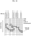
- FIG. 10 illustrates an exemplary EDD code according to embodiments.
- the geometry information about points may be encoded based on the EOD code.
- the EDD code is used for binary encoding of the positions of all points within the range of surface thickness including d1.
- a reception terminal may restore the geometry information about all points without loss.
- the code may be expressed based on 4 bits.
- Smoothing is an operation for eliminating discontinuity that may occur on the patch boundary due to deterioration of the image quality occurring during the compression process. Smoothing may be performed by the point cloud encoder or smoother:
- FIG. 11 illustrates an example of recoloring based on color values of neighboring points according to embodiments.
- the point cloud encoder or the texture image generator 40003 may generate a texture image based on recoloring.
- the texture image generation process which is similar to the geometry image generation process described above, includes generating texture images of individual patches and generating an entire texture image by arranging the texture images at determined positions. However, in the operation of generating texture images of individual patches, an image with color values (e.g., R, G, and B values) of the points constituting a point cloud corresponding to a position is generated in place of the depth values for geometry generation.
- color values e.g., R, G, and B values
- the geometry previously obtained through the smoothing process may be used.
- the positions of some points may have been shifted from the original point cloud, and accordingly a recoloring process of finding colors suitable for the changed positions may be required.
- Recoloring may be performed using the color values of neighboring points. For example, as shown in the figure, a new color value may be calculated in consideration of the color value of the nearest neighboring point and the color values of the neighboring points.
- a suitable color value for a changed position may be calculated based on the average of the attribute information about the closest original points to a point and/or the average of the attribute information about the closest original positions to the point.
- Texture images may also be generated in two layers of t0 and t1, like the geometry images, which are generated in two layers of d0 and d1.
- the point cloud encoder or the auxiliary patch info compressor may compress the auxiliary patch information (auxiliary information about the point cloud).
- the auxiliary patch info compressor compresses the auxiliary patch information generated in the patch generation, patch packing, and geometry generation processes described above.
- the auxiliary patch information may include the following parameters:
- the maximum number of candidate lists may be defined by a user.
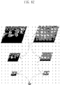
- FIG. 12 illustrates push-pull background filling according to embodiments.
- Image padding and group dilation (40006, 40007, 40008)
- the image padder according to the embodiments may fill the space except the patch area with meaningless supplemental data based on the push-pull background filling technique.
- Image padding is a process of filling the space other than the patch region with meaningless data to improve compression efficiency.
- pixel values in columns or rows close to a boundary in the patch may be copied to fill the empty space.
- a push-pull background filling method may be used. According to this method, the empty space is filled with pixel values from a low resolution image in the process of gradually reducing the resolution of a non-padded image and increasing the resolution again.
- Group dilation is a process of filling the empty spaces of a geometry image and a texture image configured in two layers, d0/d1 and t0/t1, respectively. In this process, the empty spaces of the two layers calculated through image padding are filled with the average of the values for the same position.
- FIG. 13 shows an exemplary possible traversal order for a 4 ⁇ 4 block according to embodiments.
- the occupancy map compressor may compress the previously generated occupancy map. Specifically, two methods, namely video compression for lossy compression and entropy compression for lossless compression, may be used. Video compression is described below.
- the entropy compression may be performed through the following operations.
- FIG. 14 illustrates an exemplary best traversal order according to embodiments.
- the entropy compressor may code (encode) a block based on the traversal order scheme as described above.
- the best traversal order with the minimum number of runs is selected from among the possible traversal orders and the index thereof is encoded.
- the figure illustrates a case where the third traversal order in FIG. 13 is selected.
- the number of runs may be minimized to 2, and therefore the third traversal order may be selected as the best traversal order.
- Encode lengths of the individual runs (as many as the number of runs). In the example of FIG. 14 , the lengths of the first run and the second run, 6 and 10, are sequentially encoded.
- Video compression (40009, 40010, 40011)
- the video compressor encodes a sequence of a geometry image, a texture image, an occupancy map image, and the like generated in the above-described operations, using a 2D video codec such as HEVC or WC.
- FIG. 15 illustrates an exemplary 2D video/image encoder according to embodiments.
- the figure which represents an embodiment to which the video compression or video compressor 40009, 40010, and 40011 described above is applied, is a schematic block diagram of a 2D video/image encoder 15000 configured to encode a video/image signal.
- the 2D video/image encoder 15000 may be included in the point cloud video encoder described above or may be configured as an internal/external component.
- Each component of FIG. 15 may correspond to software, hardware, processor and/or a combination thereof.
- the input image may include the geometry image, the texture image (attribute(s) image), and the occupancy map image described above.
- the output bitstream (i.e., the point cloud video/image bitstream) of the point cloud video encoder may include output bitstreams for the respective input images (i.e., the geometry image, the texture image (attribute(s) image), the occupancy map image, etc.).
- An inter-predictor 15090 and an intra-predictor 15100 may be collectively called a predictor. That is, the predictor may include the inter-predictor 15090 and the intra-predictor 15100.
- a transformer 15030, a quantizer 15040, an inverse quantizer 15050, and an inverse transformer 15060 may be included in the residual processor.
- the residual processor may further include a subtractor 15020.
- the image splitter 15010, the subtractor 15020, the transformer 15030, the quantizer 15040, the inverse quantizer 15050, the inverse transformer 15060, the adder 155, the filter 15070, the inter-predictor 15090, the intra-predictor 15100, and the entropy encoder 15110 described above may be configured by one hardware component (e.g., an encoder or a processor).
- the memory 15080 may include a decoded picture buffer (DPB) and may be configured by a digital storage medium.
- DPB decoded picture buffer
- the image splitter 15010 may spit an image (or a picture or a frame) input to the encoder 15000 into one or more processing units.
- the processing unit may be called a coding unit (CU).
- the CU may be recursively split from a coding tree unit (CTU) or a largest coding unit (LCU) according to a quad-tree binary-tree (QTBT) structure.
- CTU coding tree unit
- LCU largest coding unit
- QTBT quad-tree binary-tree
- one CU may be split into a plurality of CUs of a lower depth based on a quad-tree structure and/or a binary-tree structure.
- the quad-tree structure may be applied first and the binary-tree structure may be applied later.
- the binary-tree structure may be applied first.
- the coding procedure according to the present disclosure may be performed based on a final CU that is not split anymore.
- the LCU may be used as the final CU based on coding efficiency according to characteristics of the image.
- a CU may be recursively split into CUs of a lower depth, and a CU of the optimum size may be used as the final CU.
- the coding procedure may include prediction, transformation, and reconstruction, which will be described later.
- the processing unit may further include a prediction unit (PU) or a transform unit (TU).
- the PU and the TU may be split or partitioned from the aforementioned final CU.
- the PU may be a unit of sample prediction
- the TU may be a unit for deriving a transform coefficient and/or a unit for deriving a residual signal from the transform coefficient.
- an M ⁇ N block may represent a set of samples or transform coefficients configured in M columns and N rows.
- a sample may generally represent a pixel or a value of a pixel, and may indicate only a pixel/pixel value of a luma component, or only a pixel/pixel value of a chroma component.
- Sample may be used as a term corresponding to a pixel or a pel in one picture (or image).
- the encoder 15000 may generate a residual signal (residual block or residual sample array) by subtracting a prediction signal (predicted block or predicted sample array) output from the inter-predictor 15090 or the intra-predictor 15100 from an input image signal (original block or original sample array), and the generated residual signal is transmitted to the transformer 15030.
- the unit that subtracts the prediction signal (predicted block or predicted sample array) from the input image signal (original block or original sample array) in the encoder 15000 may be called a subtractor 15020.
- the predictor may perform prediction for a processing target block (hereinafter referred to as a current block) and generate a predicted block including prediction samples for the current block.
- the predictor may determine whether intra-prediction or inter-prediction is applied on a current block or CU basis. As will be described later in the description of each prediction mode, the predictor may generate various kinds of information about prediction, such as prediction mode information, and deliver the generated information to the entropy encoder 15110.
- the information about the prediction may be encoded and output in the form of a bitstream by the entropy encoder 15110.
- the intra-predictor 15100 may predict the current block with reference to the samples in the current picture.
- the samples may be positioned in the neighbor of or away from the current block depending on the prediction mode.
- the prediction modes may include a plurality of non-directional modes and a plurality of directional modes.
- the non-directional modes may include, for example, a DC mode and a planar mode.
- the directional modes may include, for example, 33 directional prediction modes or 65 directional prediction modes according to fineness of the prediction directions. However, this is merely an example, and more or fewer directional prediction modes may be used depending on the setting.
- the intra-predictor 15100 may determine a prediction mode to be applied to the current block, based on the prediction mode applied to the neighboring block.
- the inter-predictor 15090 may derive a predicted block for the current block based on a reference block (reference sample array) specified by a motion vector on the reference picture.
- the motion information may be predicted on a per block, subblock, or sample basis based on the correlation in motion information between the neighboring blocks and the current block.
- the motion information may include a motion vector and a reference picture index.
- the motion information may further include information about an inter-prediction direction (L0 prediction, L1 prediction, Bi prediction, etc.).
- the neighboring blocks may include a spatial neighboring block, which is present in the current picture, and a temporal neighboring block, which is present in the reference picture.
- the reference picture including the reference block may be the same as or different from the reference picture including the temporal neighboring block.
- the temporal neighboring block may be referred to as a collocated reference block or a collocated CU (colCU), and the reference picture including the temporal neighboring block may be referred to as a collocated picture (colPic).
- the inter-predictor 15090 may configure a motion information candidate list based on the neighboring blocks and generate information indicating a candidate to be used to derive a motion vector and/or a reference picture index of the current block.
- Inter-prediction may be performed based on various prediction modes. For example, in a skip mode and a merge mode, the inter-predictor 15090 may use motion information about a neighboring block as motion information about the current block. In the skip mode, unlike the merge mode, the residual signal may not be transmitted. In a motion vector prediction (MVP) mode, the motion vector of a neighboring block may be used as a motion vector predictor and the motion vector difference may be signaled to indicate the motion vector of the current block.
- MVP motion vector prediction
- the prediction signal generated by the inter-predictor 15090 or the intra-predictor 15100 may be used to generate a reconstruction signal or to generate a residual signal.
- the transformer 15030 may generate transform coefficients by applying a transformation technique to the residual signal.
- the transformation technique may include at least one of discrete cosine transform (DCT), discrete sine transform (DST), Karhunen-Loève transform (KLT), graph-based transform (GBT), or conditionally non-linear transform (CNT).
- DCT discrete cosine transform
- DST discrete sine transform
- KLT Karhunen-Loève transform
- GBT graph-based transform
- CNT conditionally non-linear transform
- the GBT refers to transformation obtained from a graph depicting the relationship between pixels.
- the CNT refers to transformation obtained based on a prediction signal generated based on all previously reconstructed pixels.
- the transformation operation may be applied to pixel blocks having the same size of a square, or may be applied to blocks of a variable size other than the square.
- the quantizer 15040 may quantize the transform coefficients and transmit the same to the entropy encoder 15110.
- the entropy encoder 15110 may encode the quantized signal (information about the quantized transform coefficients) and output a bitstream of the encoded signal.
- the information about the quantized transform coefficients may be referred to as residual information.
- the quantizer 15040 may rearrange the quantized transform coefficients, which are in a block form, in the form of a one-dimensional vector based on a coefficient scan order, and generate information about the quantized transform coefficients based on the quantized transform coefficients in the form of the one-dimensional vector.
- the entropy encoder 15110 may employ various encoding techniques such as, for example, exponential Golomb, context-adaptive variable length coding (CAVLC), and context-adaptive binary arithmetic coding (CABAC).
- the entropy encoder 15110 may encode information necessary for video/image reconstruction (e.g., values of syntax elements) together with or separately from the quantized transform coefficients.
- the encoded information (e.g., encoded video/image information) may be transmitted or stored in the form of a bitstream on a network abstraction layer (NAL) unit basis.
- NAL network abstraction layer
- the bitstream may be transmitted over a network or may be stored in a digital storage medium.
- the network may include a broadcast network and/or a communication network
- the digital storage medium may include various storage media such as USB, SD, CD, DVD, Blu-ray, HDD, and SSD.
- a transmitter (not shown) to transmit the signal output from the entropy encoder 15110 and/or a storage (not shown) to store the signal may be configured as internal/external elements of the encoder 15000. Alternatively, the transmitter may be included in the entropy encoder 15110.
- the quantized transform coefficients output from the quantizer 15040 may be used to generate a prediction signal.
- inverse quantization and inverse transform may be applied to the quantized transform coefficients through the inverse quantizer 15050 and the inverse transformer 15060 to reconstruct the residual signal (residual block or residual samples).
- the adder 155 may add the reconstructed residual signal to the prediction signal output from the inter-predictor 15090 or the intra-predictor 15100. Thereby, a reconstructed signal (reconstructed picture, reconstructed block, reconstructed sample array) may be generated.
- the predicted block may be used as the reconstructed block.
- the adder 155 may be called a reconstructor or a reconstructed block generator.
- the generated reconstructed signal may be used for intra-prediction of the next processing target block in the current picture, or may be used for inter-prediction of the next picture through filtering as described below.
- the filter 15070 may improve subjective/objective image quality by applying filtering to the reconstructed signal.
- the filter 15070 may generate a modified reconstructed picture by applying various filtering techniques to the reconstructed picture, and the modified reconstructed picture may be stored in the memory 15080, specifically, the DPB of the memory 15080.
- the various filtering techniques may include, for example, deblocking filtering, sample adaptive offset, adaptive loop filtering, and bilateral filtering.
- the filter 15070 may generate various kinds of information about filtering and deliver the generated information to the entropy encoder 15110.
- the information about filtering may be encoded and output in the form of a bitstream by the entropy encoder 15110.
- the modified reconstructed picture transmitted to the memory 15080 may be used as a reference picture by the inter-predictor 15090.
- the encoder may avoid prediction mismatch between the encoder 15000 and the decoder and improve encoding efficiency.
- the DPB of the memory 15080 may store the modified reconstructed picture so as to be used as a reference picture by the inter-predictor 15090.
- the memory 15080 may store the motion information about a block from which the motion information in the current picture is derived (or encoded) and/or the motion information about the blocks in a picture that has already been reconstructed.
- the stored motion information may be delivered to the inter-predictor 15090 so as to be used as motion information about a spatial neighboring block or motion information about a temporal neighboring block.
- the memory 15080 may store the reconstructed samples of the reconstructed blocks in the current picture and deliver the reconstructed samples to the intra-predictor 15100.
- At least one of the prediction, transform, and quantization procedures described above may be skipped.
- the prediction, transform, and quantization procedures may be skipped, and the value of the original sample may be encoded and output in the form of a bitstream.
- FIG. 16 illustrates an exemplary V-PCC decoding process according to embodiments.
- V-PCC decoding process or V-PCC decoder may follow the reverse process of the V-PCC encoding process (or encoder) of FIG. 4 .
- Each component in FIG. 16 may correspond to software, hardware, a processor, and/or a combination thereof.
- the demultiplexer 16000 demultiplexes the compressed bitstream to output a compressed texture image, a compressed geometry image, a compressed occupancy map, and compressed auxiliary patch information.
- the video decompression or video decompressor 16001, 16002 decompresses (or decodes) each of the compressed texture image and the compressed geometry image.
- the occupancy map decompression or occupancy map decompressor 16003 decompresses the compressed occupancy map.
- the auxiliary patch info decompression or auxiliary patch info decompressor 16004 decompresses auxiliary patch information.
- the geometry reconstruction or geometry reconstructor 16005 restores (reconstructs) the geometry information based on the decompressed geometry image, the decompressed occupancy map, and/or the decompressed auxiliary patch information. For example, the geometry changed in the encoding process may be reconstructed.
- the smoothing or smoother 16006 may apply smoothing to the reconstructed geometry. For example, smoothing filtering may be applied.
- the texture reconstruction or texture reconstructor 16007 reconstructs the texture from the decompressed texture image and/or the smoothed geometry.
- the color smoothing or color smoother 16008 smoothes color values from the reconstructed texture. For example, smoothing filtering may be applied.
- reconstructed point cloud data may be generated.
- the figure illustrates a decoding process of the V-PCC for reconstructing a point cloud by decoding the compressed occupancy map, geometry image, texture image, and auxiliary path information.
- Each process according to the embodiments is operated as follows.
- Video decompression is a reverse process of the video compression described above.
- a 2D video codec such as HEVC or VVC is used to decode a compressed bitstream containing the geometry image, texture image, and occupancy map image generated in the above-described process.
- FIG. 17 illustrates an exemplary 2D video/image decoder according to embodiments.
- the 2D video/image decoder may follow the reverse process of the 2D video/image encoder of FIG. 15 .
- the 2D video/image decoder of FIG. 17 is an embodiment of the video decompression or video decompressor of FIG. 16 .
- FIG. 17 is a schematic block diagram of a 2D video/image decoder 17000 by which decoding of a video/image signal is performed.
- the 2D video/image decoder 17000 may be included in the point cloud video decoder of FIG. 1 , or may be configured as an internal/external component.
- Each component in FIG. 17 may correspond to software, hardware, a processor, and/or a combination thereof.
- the input bitstream may include bitstreams for the geometry image, texture image (attribute(s) image), and occupancy map image described above.
- the reconstructed image (or the output image or the decoded image) may represent a reconstructed image for the geometry image, texture image (attribute(s) image), and occupancy map image described above.
- an inter-predictor 17070 and an intra-predictor 17080 may be collectively referred to as a predictor. That is, the predictor may include the inter-predictor 17070 and the intra-predictor 17080.
- An inverse quantizer 17020 and an inverse transformer 17030 may be collectively referred to as a residual processor. That is, the residual processor may include the inverse quantizer 17020 and the inverse transformer 17030.
- the entropy decoder 17010, the inverse quantizer 17020, the inverse transformer 17030, the adder 17040, the filter 17050, the inter-predictor 17070, and the intra-predictor 17080 described above may be configured by one hardware component (e.g., a decoder or a processor) according to an embodiment.
- the memory 170 may include a decoded picture buffer (DPB) or may be configured by a digital storage medium.
- DPB decoded picture buffer
- the decoder 17000 may reconstruct an image in a process corresponding to the process in which the video/image information is processed by the encoder of FIG. 0.2-1.
- the decoder 17000 may perform decoding using a processing unit applied in the encoder.
- the processing unit of decoding may be, for example, a CU.
- the CU may be split from a CTU or an LCU along a quad-tree structure and/or a binary-tree structure. Then, the reconstructed video signal decoded and output through the decoder 17000 may be played through a player.
- the decoder 17000 may receive a signal output from the encoder in the form of a bitstream, and the received signal may be decoded through the entropy decoder 17010.
- the entropy decoder 17010 may parse the bitstream to derive information (e.g., video/image information) necessary for image reconstruction (or picture reconstruction).
- the entropy decoder 17010 may decode the information in the bitstream based on a coding technique such as exponential Golomb coding, CAVLC, or CABAC, output values of syntax elements required for image reconstruction, and quantized values of transform coefficients for the residual.
- a bin corresponding to each syntax element in the bitstream may be received, and a context model may be determined based on decoding target syntax element information and decoding information about neighboring and decoding target blocks or information about a symbol/bin decoded in a previous step. Then, the probability of occurrence of a bin may be predicted according to the determined context model, and arithmetic decoding of the bin may be performed to generate a symbol corresponding to the value of each syntax element.
- the context model may be updated based on the information about the symbol/bin decoded for the context model of the next symbol/bin.
- Information about the prediction in the information decoded by the entropy decoder 17010 may be provided to the predictors (the inter-predictor 17070 and the intra-predictor 17080), and the residual values on which entropy decoding has been performed by the entropy decoder 17010, that is, the quantized transform coefficients and related parameter information, may be input to the inverse quantizer 17020.
- information about filtering of the information decoded by the entropy decoder 17010 may be provided to the filter 17050.
- a receiver (not shown) configured to receive a signal output from the encoder may be further configured as an internal/external element of the decoder 17000. Alternatively, the receiver may be a component of the entropy decoder 17010.
- the inverse quantizer 17020 may output transform coefficients by inversely quantizing the quantized transform coefficients.
- the inverse quantizer 17020 may rearrange the quantized transform coefficients in the form of a two-dimensional block. In this case, the rearrangement may be performed based on the coefficient scan order implemented by the encoder.
- the inverse quantizer 17020 may perform inverse quantization on the quantized transform coefficients using a quantization parameter (e.g., quantization step size information), and acquire transform coefficients.
- a quantization parameter e.g., quantization step size information
- the inverse transformer 17030 acquires a residual signal (residual block and residual sample array) by inversely transforming the transform coefficients.
- the predictor may perform prediction on the current block and generate a predicted block including prediction samples for the current block.
- the predictor may determine whether intra-prediction or inter-prediction is to be applied to the current block based on the information about the prediction output from the entropy decoder 17010, and may determine a specific intra-/inter-prediction mode.
- the intra-predictor 265 may predict the current block with reference to the samples in the current picture.
- the samples may be positioned in the neighbor of or away from the current block depending on the prediction mode.
- the prediction modes may include a plurality of non-directional modes and a plurality of directional modes.
- the intra-predictor 17080 may determine a prediction mode to be applied to the current block, using the prediction mode applied to the neighboring block.
- the inter-predictor 17070 may derive a predicted block for the current block based on a reference block (reference sample array) specified by a motion vector on the reference picture.
- the motion information may be predicted on a per block, subblock, or sample basis based on the correlation in motion information between the neighboring blocks and the current block.
- the motion information may include a motion vector and a reference picture index.
- the motion information may further include information about an inter-prediction direction (L0 prediction, L1 prediction, Bi prediction, etc.).
- the neighboring blocks may include a spatial neighboring block, which is present in the current picture, and a temporal neighboring block, which is present in the reference picture.
- the inter-predictor 17070 may configure a motion information candidate list based on neighboring blocks and derive a motion vector of the current block and/or a reference picture index based on the received candidate selection information.
- Inter-prediction may be performed based on various prediction modes.
- the information about the prediction may include information indicating an inter-prediction mode for the current block.
- the adder 17040 may add the acquired residual signal to the prediction signal (predicted block or prediction sample array) output from the inter-predictor 17070 or the intra-predictor 17080, thereby generating a reconstructed signal (a reconstructed picture, a reconstructed block, or a reconstructed sample array).
- the predicted block may be used as the reconstructed block.
- the adder 17040 may be called a reconstructor or a reconstructed block generator.
- the generated reconstructed signal may be used for intra-prediction of the next processing target block in the current picture, or may be used for inter-prediction of the next picture through filtering as described below.
- the filter 17050 may improve subjective/objective image quality by applying filtering to the reconstructed signal.
- the filter 17050 may generate a modified reconstructed picture by applying various filtering techniques to the reconstructed picture, and may transmit the modified reconstructed picture to the memory 250, specifically, the DPB of the memory 17060.
- the various filtering techniques may include, for example, deblocking filtering, sample adaptive offset, adaptive loop filtering, and bilateral filtering.
- the reconstructed picture stored in the DPB of the memory 17060 may be used as a reference picture in the inter-predictor 17070.
- the memory 17060 may store the motion information about a block from which the motion information is derived (or decoded) in the current picture and/or the motion information about the blocks in a picture that has already been reconstructed.
- the stored motion information may be delivered to the inter-predictor 17070 so as to be used as the motion information about a spatial neighboring block or the motion information about a temporal neighboring block.
- the memory 17060 may store the reconstructed samples of the reconstructed blocks in the current picture, and deliver the reconstructed samples to the intra-predictor 17080.
- the embodiments described regarding the filter 160, the inter-predictor 180, and the intra-predictor 185 of the encoding device 100 may be applied to the filter 17050, the inter-predictor 17070 and the intra-predictor 17080 of the decoder 17000, respectively, in the same or corresponding manner.
- At least one of the prediction, transform, and quantization procedures described above may be skipped.
- the prediction, transform, and quantization procedures may be skipped, and the value of a decoded sample may be used as a sample of the reconstructed image.
- Occupancy map decompression is a process for reconstructing the occupancy map by decompressing the occupancy map bitstream.
- the auxiliary patch information may be reconstructed by performing the reverse process of the aforementioned auxiliary patch info compression and decoding the compressed auxiliary patch info bitstream.
- a patch is extracted from the geometry image using the reconstructed occupancy map, the 2D position/size information about the patch included in the auxiliary patch info, and the information about mapping between a block and the patch. Then, a point cloud is reconstructed in a 3D space based on the geometry image of the extracted patch and the 3D position information about the patch included in the auxiliary patch info.
- Smoothing which is the same as the smoothing in the encoding process described above, is a process for eliminating discontinuity that may occur on the patch boundary due to deterioration of the image quality occurring during the compression process.
- Texture reconstruction is a process of reconstructing a color point cloud by assigning color values to each point constituting a smoothed point cloud. It may be performed by assigning color values corresponding to a texture image pixel at the same position as in the geometry image in the 2D space to points of a point of a point cloud corresponding to the same position in the 3D space, based on the mapping information about the geometry image and the point cloud in the geometry reconstruction process described above.
- Color smoothing is similar to the process of geometry smoothing described above. Color smoothing is a process for eliminating discontinuity that may occur on the patch boundary due to deterioration of the image quality occurring during the compression process. Color smoothing may be performed through the following operations:
- FIG. 18 is a flowchart illustrating operation of a transmission device according to embodiments of the present disclosure.
- the transmission device may correspond to the transmission device of FIG. 1 , the encoding process of FIG. 4 , and the 2D video/image encoder of FIG. 15 , or perform some/all of the operations thereof.
- Each component of the transmission device may correspond to software, hardware, a processor and/or a combination thereof.
- An operation process of the transmission terminal for compression and transmission of point cloud data using V-PCC may be performed as illustrated in the figure.
- the point cloud data transmission device may be referred to as a transmission device.
- a patch for 2D image mapping of a point cloud is generated.
- Auxiliary patch information is generated as a result of the patch generation.
- the generated information may be used in the processes of geometry image generation, texture image generation, and geometry reconstruction for smoothing.
- a patch packing process of mapping the generated patches into the 2D image is performed.
- an occupancy map may be generated.
- the occupancy map may be used in the processes of geometry image generation, texture image generation, and geometry reconstruction for smoothing.
- a geometry image generator 18002 generates a geometry image based on the auxiliary patch information and the occupancy map.
- the generated geometry image is encoded into one bitstream through video encoding.
- An encoding preprocessor 18003 may include an image padding procedure.
- the geometry image regenerated by decoding the generated geometry image or the encoded geometry bitstream may be used for 3D geometry reconstruction and then be subjected to a smoothing process.
- a texture image generator 18004 may generate a texture image based on the (smoothed) 3D geometry, the point cloud, the auxiliary patch information, and the occupancy map.
- the generated texture image may be encoded into one video bitstream.
- a metadata encoder 18005 may encode the auxiliary patch information into one metadata bitstream.
- a video encoder 18006 may encode the occupancy map into one video bitstream.
- a multiplexer 18007 may multiplex the video bitstreams of the generated geometry image, texture image, and occupancy map and the metadata bitstream of the auxiliary patch information into one bitstream.
- a transmitter 18008 may transmit the bitstream to the reception terminal.
- the video bitstreams of the generated geometry image, texture image, and the occupancy map and the metadata bitstream of the auxiliary patch information may be processed into a file of one or more track data or encapsulated into segments and may be transmitted to the reception terminal through the transmitter.
- FIG. 19 is a flowchart illustrating operation of a reception device according to embodiments.
- the reception device may correspond to the reception device of FIG. 1 , the decoding process of FIG. 16 , and the 2D video/image encoder of FIG. 17 , or perform some/all of the operations thereof.
- Each component of the reception device may correspond to software, hardware, a processor and/or a combination thereof.
- the operation of the reception terminal for receiving and reconstructing point cloud data using V-PCC may be performed as illustrated in the figure.
- the operation of the V-PCC reception terminal may follow the reverse process of the operation of the V-PCC transmission terminal of FIG. 18 .
- the point cloud data reception device may be referred to as a reception device.
- the bitstream of the received point cloud is demultiplexed into the video bitstreams of the compressed geometry image, texture image, occupancy map and the metadata bitstream of the auxiliary patch information by a demultiplexer 19000 after file/segment decapsulation.
- a video decoder 19001 and a metadata decoder 19002 decode the demultiplexed video bitstreams and metadata bitstream.
- 3D geometry is reconstructed by a geometry reconstructor 19003 based on the decoded geometry image, occupancy map, and auxiliary patch information, and is then subjected to a smoothing process performed by a smoother 19004.
- a color point cloud image/picture may be reconstructed by a texture reconstructor 19005 by assigning color values to the smoothed 3D geometry based on the texture image.
- a color smoothing process may be additionally performed to improve the objective/subjective visual quality, and a modified point cloud image/picture derived through the color smoothing process is shown to the user through the rendering process (through, for example, the point cloud renderer). In some cases, the color smoothing process may be skipped.
- FIG. 20 illustrates an exemplary architecture for V-PCC based storage and streaming of point cloud data according to embodiments.
- a part/the entirety of the system of FIG. 20 may include some or all of the transmission device and reception device of FIG. 1 , the encoding process of FIG. 4 , the 2D video/image encoder of FIG. 15 , the decoding process of FIG. 16 , the transmission device of FIG. 18 , and/or the reception device of FIG. 19 .
- Each component in the figure may correspond to software, hardware, a processor and/or a combination thereof.
- FIGS. 20 to 22 are diagrams illustrating a structure in which a system is additionally connected to the transmission device and the reception device according to embodiments.
- the transmission device and the reception device the system according to embodiments may be referred to as a transmission/reception apparatus according to the embodiments.
- the transmitting device corresponding to FIG. 18 or the like may generate a container suitable for a data format for transmission of a bitstream containing encoded point cloud data.
- the V-PCC system may create a container including point cloud data, and may further add additional data necessary for efficient transmission/reception to the container.
- the reception device may receive and parse the container based on the system shown in FIGS. 20 to 22 .
- the reception device corresponding to FIG. 19 or the like may decode and restore point cloud data from the parsed bitstream.
- the figure shows the overall architecture for storing or streaming point cloud data compressed based on video-based point cloud compression (V-PCC).
- the process of storing and streaming the point cloud data may include an acquisition process, an encoding process, a transmission process, a decoding process, a rendering process, and/or a feedback process.
- the embodiments propose a method of effectively providing point cloud media/content/data.
- a point cloud acquirer 20000 may acquire a point cloud video.
- one or more cameras may acquire point cloud data through capture, composition or generation of a point cloud.
- a point cloud video including a 3D position (which may be represented by x, y, and z position values, etc.) (hereinafter referred to as geometry) of each point and attributes (color, reflectance, transparency, etc.) of each point may be acquired.
- geometry which may be represented by x, y, and z position values, etc.
- attributes color, reflectance, transparency, etc.
- PLY Polygon File format
- For point cloud data having multiple frames, one or more files may be acquired.
- point cloud related metadata e.g., metadata related to capture, etc.
- Post-processing for improving the quality of the content may be needed for the captured point cloud video.
- the maximum/minimum depth may be adjusted within the range provided by the camera equipment. Even after the adjustment, point data of an unwanted area may still be present. Accordingly, post-processing of removing the unwanted area (e.g., the background) or recognizing a connected space and filling the spatial holes may be performed.
- point clouds extracted from the cameras sharing a spatial coordinate system may be integrated into one piece of content through the process of transforming each point into a global coordinate system based on the coordinates of the location of each camera acquired through a calibration process. Thereby, a point cloud video with a high density of points may be acquired.
- a point cloud pre-processor 20001 may generate one or more pictures/frames of the point cloud video.
- a picture/frame may generally represent a unit representing one image in a specific time interval.
- patches sets of points that constitute the point cloud video, wherein the points belonging to the same patch are adjacent to each other in the 3D space and are mapped in the same direction among the planar faces of a 6-face bounding box when mapped to a 2D image
- an occupancy map picture/frame of a binary map which indicates presence or absence of data at the corresponding position in the 2D plane with a value of 0 or 1 may be generated.
- a geometry picture/frame which is in the form of a depth map that represents the information about the position (geometry) of each point constituting the point cloud video on a patch-by-patch basis
- a texture picture/frame which represents the color information about each point constituting the point cloud video on a patch-by-patch basis, may be generated.
- metadata needed to reconstruct the point cloud from the individual patches may be generated.
- the metadata may include information about the patches, such as the position and size of each patch in the 2D/3D space.
- a point cloud video encoder 20002 may encode one or more video streams related to a point cloud video.
- One video may include multiple frames, and one frame may correspond to a still image/picture.
- the point cloud video may include a point cloud image/frame/picture, and the term "point cloud video" may be used interchangeably with the point cloud video/frame/picture.
- the point cloud video encoder may perform a video-based point cloud compression (V-PCC) procedure.
- the point cloud video encoder may perform a series of procedures such as prediction, transform, quantization, and entropy coding for compression and coding efficiency.
- the encoded data (encoded video/image information) may be output in the form of a bitstream.
- the point cloud video encoder may encode point cloud video by dividing the same into a geometry video, an attribute video, an occupancy map video, and metadata, for example, information about patches, as described below.
- the geometry video may include a geometry image
- the attribute video may include an attribute image
- the occupancy map video may include an occupancy map image.
- the patch data which is auxiliary information, may include patch related information.
- the attribute video/image may include a texture video/image.
- a point cloud image encoder 20003 may encode one or more images related to a point cloud video.
- the point cloud image encoder may perform a video-based point cloud compression (V-PCC) procedure.
- the point cloud image encoder may perform a series of procedures such as prediction, transform, quantization, and entropy coding for compression and coding efficiency.
- the encoded image may be output in the form of a bitstream.
- the point cloud image encoder may encode the point cloud image by dividing the same into a geometry image, an attribute image, an occupancy map image, and metadata, for example, information about patches, as described below.
- the point cloud video encoder and/or the point cloud image encoder according to the embodiments may generate a PCC bitstream (G-PCC and/or V-PCC bitstream) according to the embodiments.
- the video encoder 20002, the image encoder 20003, the video decoding 20006, and the image decoding may be performed by one encoder/decoder as described above, and may be performed along separate paths as shown in the figure.
- the encoded point cloud data and/or point cloud-related metadata may be encapsulated into a file or a segment for streaming.
- the point cloud-related metadata may be received from the metadata processor or the like.
- the metadata processor may be included in the point cloud video/image encoder or may be configured as a separate component/module.
- the encapsulation processor may encapsulate the corresponding video/image/metadata in a file format such as ISOBMFF or in the form of a DASH segment or the like.
- the encapsulation processor may include the point cloud metadata in the file format.
- the point cloud-related metadata may be included, for example, in boxes at various levels on the ISOBMFF file format or as data in a separate track within the file.
- the encapsulation processor may encapsulate the point cloud-related metadata into a file.
- the encapsulation or encapsulator may divide the G-PCC/V-PCC bitstream into one or multiple tracks and store the same in a file, and may also encapsulate signaling information for this operation.
- the atlas stream included on the G-PCC/V-PCC bitstream may be stored as a track in the file, and related signaling information may be stored.
- an SEI message present in the G-PCC/V-PCC bitstream may be stored in a track in the file and related signaling information may be stored.
- a transmission processor may perform processing of the encapsulated point cloud data for transmission according to the file format.
- the transmission processor may be included in the transmitter or may be configured as a separate component/module.
- the transmission processor may process the point cloud data according to a transmission protocol.
- the processing for transmission may include processing for delivery over a broadcast network and processing for delivery through a broadband.
- the transmission processor may receive point cloud-related metadata from the metadata processor as well as the point cloud data, and perform processing of the point cloud video data for transmission.
- the transmitter may transmit a point cloud bitstream or a file/segment including the bitstream to the receiver of the reception device over a digital storage medium or a network.
- processing according to any transmission protocol may be performed.
- the data processed for transmission may be delivered over a broadcast network and/or through a broadband.
- the data may be delivered to the reception side in an on-demand manner.
- the digital storage medium may include various storage media such as USB, SD, CD, DVD, Blu-ray, HDD, and SSD.
- the transmitter may include an element for generating a media file in a predetermined file format, and may include an element for transmission over a broadcast/communication network.
- the receiver may extract the bitstream and transmit the extracted bitstream to the decoder.
- the receiver may receive point cloud data transmitted by the point cloud data transmission device according to the present disclosure. Depending on the transmission channel, the receiver may receive the point cloud data over a broadcast network or through a broadband. Alternatively, the point cloud data may be received through the digital storage medium. The receiver may include a process of decoding the received data and rendering the data according to the viewport of the user.
- the reception processor may perform processing on the received point cloud video data according to the transmission protocol.
- the reception processor may be included in the receiver or may be configured as a separate component/module.
- the reception processor may reversely perform the process of the transmission processor above described so as to correspond to the processing for transmission performed at the transmission side.
- the reception processor may deliver the acquired point cloud video to a decapsulation processor, and the acquired point cloud-related metadata to a metadata parser.
- a decapsulation processor (file/segment decapsulation) 20005 may decapsulate the point cloud data received in the form of a file from the reception processor.
- the decapsulation processor may decapsulate files according to ISOBMFF or the like, and may acquire a point cloud bitstream or point cloud-related metadata (or a separate metadata bitstream).
- the acquired point cloud bitstream may be delivered to the point cloud decoder, and the acquired point cloud video-related metadata (metadata bitstream) may be delivered to the metadata processor.
- the point cloud bitstream may include the metadata (metadata bitstream).
- the metadata processor may be included in the point cloud decoder or may be configured as a separate component/module.
- the point cloud video-related metadata acquired by the decapsulation processor may take the form of a box or track in the file format.
- the decapsulation processor may receive metadata necessary for decapsulation from the metadata processor, when necessary.
- the point cloud-related metadata may be delivered to the point cloud decoder and used in a point cloud decoding procedure, or may be transferred to the renderer and used in a point cloud rendering procedure.
- the point cloud video decoder 20006 may receive the bitstream and decode the video/image by performing an operation corresponding to the operation of the point cloud video encoder.
- the point cloud video decoder may decode the point cloud video by dividing the same into a geometry video, an attribute video, an occupancy map video, and auxiliary patch information as described below.
- the geometry video may include a geometry image
- the attribute video may include an attribute image
- the occupancy map video may include an occupancy map image.
- the auxiliary information may include auxiliary patch information.
- the attribute video/image may include a texture video/image.
- the 3D geometry may be reconstructed based on the decoded geometry image, the occupancy map, and auxiliary patch information, and then may be subjected to a smoothing process.
- the color point cloud image/picture may be reconstructed by assigning a color value to the smoothed 3D geometry based on the texture image.
- the renderer may render the reconstructed geometry and the color point cloud image/picture.
- the rendered video/image may be displayed through the display. All or part of the rendered result may be shown to the user through a VR/AR display or a typical display.
- a sensor/tracker (sensing/tracking) 20007 acquires orientation information and/or user viewport information from the user or the reception side and delivers the orientation information and/or the user viewport information to the receiver and/or the transmitter.
- the orientation information may represent information about the position, angle, movement, etc. of the user's head, or represent information about the position, angle, movement, etc. of a device through which the user is viewing a video/image. Based on this information, information about the area currently viewed by the user in a 3D space, that is, viewport information may be calculated.
- the viewport information may be information about an area in a 3D space currently viewed by the user through a device or an HMD
- a device such as a display may extract a viewport area based on the orientation information, a vertical or horizontal FOV supported by the device, and the like.
- the orientation or viewport information may be extracted or calculated at the reception side.
- the orientation or viewport information analyzed at the reception side may be transmitted to the transmission side on a feedback channel.
- the receiver may efficiently extract or decode only media data of a specific area, i.e., the area indicated by the orientation information and/or the viewport information from the file.
- the transmitter may efficiently encode only the media data of the specific area, that is, the area indicated by the orientation information and/or the viewport information, or generate and transmit a file therefor.
- the renderer may render the decoded point cloud data in a 3D space.
- the rendered video/image may be displayed through the display.
- the user may view all or part of the rendered result through a VR/AR display or a typical display.
- the feedback process may include transferring various kinds of feedback information that may be acquired in the rendering/displaying process to the transmitting side or the decoder of the receiving side. Through the feedback process, interactivity may be provided in consumption of point cloud data. According to an embodiment, head orientation information, viewport information indicating an area currently viewed by a user, and the like may be delivered to the transmitting side in the feedback process. According to an embodiment, the user may interact with what is implemented in the VR/AR/MR/self-driving environment. In this case, information related to the interaction may be delivered to the transmitting side or a service provider in the feedback process. According to an embodiment, the feedback process may be skipped.
- the above-described feedback information may not only be transmitted to the transmitting side, but also be consumed at the receiving side. That is, the decapsulation processing, decoding, and rendering processes at the receiving side may be performed based on the above-described feedback information.
- the point cloud data about the area currently viewed by the user may be preferentially decapsulated, decoded, and rendered based on the orientation information and/or the viewport information.
- FIG. 21 is an exemplary block diagram of a device for storing and transmitting point cloud data according to embodiments.
- FIG. 21 shows a point cloud system according to embodiments.
- a part/the entirety of the system may include some or all of the transmission device and reception device of FIG. 1 , the encoding process of FIG. 4 , the 2D video/image encoder of FIG. 15 , the decoding process of FIG. 16 , the transmission device of FIG. 18 , and/or the reception device of FIG. 19 .
- it may be included or corresponded to a part/the entirety of the system of FIG. 20 .
- a point cloud data transmission device may be configured as shown in the figure.
- Each element of the transmission device may be a module/unit/component/hardware/software/a processor.
- the geometry, attribute, auxiliary data, and mesh data of the point cloud may each be configured as a separate stream or stored in different tracks in a file. Furthermore, they may be included in a separate segment.
- a point cloud acquirer (point cloud acquisition) 21000 acquires a point cloud.
- one or more cameras may acquire point cloud data through capture, composition or generation of a point cloud.
- point cloud data including a 3D position (which may be represented by x, y, and z position values, etc.) (hereinafter referred to as geometry) of each point and attributes (color, reflectance, transparency, etc.) of each point may be acquired.
- geometry which may be represented by x, y, and z position values, etc.
- attributes color, reflectance, transparency, etc.
- PLY Polygon File format
- point cloud related metadata e.g., metadata related to capture, etc.
- a patch generator (or patch generation) 21002 generates patches from the point cloud data.
- the patch generator generates point cloud data or point cloud video as one or more pictures/frames.
- a picture/frame may generally represent a unit representing one image in a specific time interval.
- points constituting the point cloud video is divided into one or more patches (sets of points that constitute the point cloud video, wherein the points belonging to the same patch are adjacent to each other in the 3D space and are mapped in the same direction among the planar faces of a 6-face bounding box when mapped to a 2D image) and mapped to a 2D plane
- an occupancy map picture/frame in a binary map which indicates presence or absence of data at the corresponding position in the 2D plane with 0 or 1 may be generated.
- a geometry picture/frame which is in the form of a depth map that represents the information about the position (geometry) of each point constituting the point cloud video on a patch-by-patch basis
- a texture picture/frame which represents the color information about each point constituting the point cloud video on a patch-by-patch basis, may be generated.
- metadata needed to reconstruct the point cloud from the individual patches may be generated.
- the metadata may include information about the patches, such as the position and size of each patch in the 2D/3D space.
- the patches may be used for 2D image mapping.
- the point cloud data may be projected onto each face of a cube.
- patch generation a geometry image, one or more attribute images, an occupancy map, auxiliary data, and/or mesh data may be generated based on the generated patches.
- Geometry image generation, attribute image generation, occupancy map generation, auxiliary data generation, and/or mesh data generation are performed by a pre-processor or a controller.
- geometry image generation 21002 a geometry image is generated based on the result of the patch generation. Geometry represents a point in a 3D space.
- the geometry image is generated using the occupancy map, which includes information related to 2D image packing of the patches, auxiliary data (patch data), and/or mesh data based on the patches.
- the geometry image is related to information such as a depth (e.g., near, far) of the patch generated after the patch generation.
- an attribute image is generated.
- an attribute may represent a texture.
- the texture may be a color value that matches each point.
- images of a plurality of attributes (such as color and reflectance) (N attributes) including a texture may be generated.
- the plurality of attributes may include material information and reflectance.
- the attributes may additionally include information indicating a color, which may vary depending on viewing angle and light even for the same texture.
- occupancy map generation 21004 an occupancy map is generated from the patches.
- the occupancy map includes information indicating presence or absence of data in the pixel, such as the corresponding geometry or attribute image.
- auxiliary data including information about the patches is generated. That is, the auxiliary data represents metadata about a patch of a point cloud object. For example, it may represent information such as normal vectors for the patches. Specifically, the auxiliary data may include information needed to reconstruct the point cloud from the patches (e.g., information about the positions, sizes, and the like of the patches in 2D/3D space, and projection (normal) plane identification information, patch mapping information, etc.)
- mesh data is generated from the patches.
- Mesh represents connection between neighboring points. For example, it may represent data of a triangular shape.
- the mesh data refers to connectivity between the points.
- a point cloud pre-processor or controller generates metadata related to patch generation, geometry image generation, attribute image generation, occupancy map generation, auxiliary data generation, and mesh data generation.
- the point cloud transmission device performs video encoding and/or image encoding in response to the result generated by the pre-processor.
- the point cloud transmission device may generate point cloud image data as well as point cloud video data.
- the point cloud data may have only video data, only image data, and/or both video data and image data.
- a video encoder 21007 performs geometry video compression, attribute video compression, occupancy map compression, auxiliary data compression, and/or mesh data compression.
- the video encoder generates video stream(s) containing encoded video data.
- point cloud geometry video data is encoded.
- attribute video data of the point cloud is encoded.
- auxiliary data compression auxiliary data associated with the point cloud video data is encoded.
- mesh data compression mesh data of the point cloud video data is encoded. The respective operations of the point cloud video encoder may be performed in parallel.
- An image encoder 21008 performs geometry image compression, attribute image compression, occupancy map compression, auxiliary data compression, and/or mesh data compression.
- the image encoder generates image(s) containing encoded image data.
- the point cloud geometry image data is encoded.
- the attribute image data of the point cloud is encoded.
- the auxiliary data compression the auxiliary data associated with the point cloud image data is encoded.
- the mesh data compression the mesh data associated with the point cloud image data is encoded. The respective operations of the point cloud image encoder may be performed in parallel.
- the video encoder and/or the image encoder may receive metadata from the pre-processor.
- the video encoder and/or the image encoder may perform each encoding process based on the metadata.
- a file/segment encapsulator (file/segment encapsulation) 21009 encapsulates the video stream(s) and/or image(s) in the form of a file and/or segment.
- the file/segment encapsulator performs video track encapsulation, metadata track encapsulation, and/or image encapsulation.
- one or more video streams may be encapsulated into one or more tracks.
- Metadata related to a video stream and/or an image may be encapsulated in one or more tracks.
- the metadata includes data related to the content of the point cloud data. For example, it may include initial viewing orientation metadata.
- the metadata may be encapsulated into a metadata track, or may be encapsulated together in a video track or an image track.
- one or more images may be encapsulated into one or more tracks or items.
- the four video streams and two images may be encapsulated in one file.
- the point cloud video encoder and/or the point cloud image encoder according to the embodiments may generate a G-PCC/V-PCC bitstream according to the embodiments.
- the file/segment encapsulator may receive metadata from the pre-processor.
- the file/segment encapsulator may perform encapsulation based on the metadata.
- a file and/or a segment generated by the file/segment encapsulation are transmitted by the point cloud transmission device or the transmitter.
- the segment(s) may be delivered based on a DASHbased protocol.
- the encapsulation or encapsulator may divide the V-PCC bitstream into one or multiple tracks and store the same in a file, and may also encapsulate signaling information for this operation.
- the atlas stream included on the V-PCC bitstream may be stored as a track in the file, and related signaling information may be stored.
- an SEI message present in the V-PCC bitstream may be stored in a track in the file and related signaling information may be stored.
- the transmitter may transmit a point cloud bitstream or a file/segment including the bitstream to the receiver of the reception device over a digital storage medium or a network. Processing according to any transmission protocol may be performed for transmission.
- the data that has been processed for transmission may be delivered over a broadcast network and/or through a broadband.
- the data may be delivered to the receiving side in an on-demand manner.
- the digital storage medium may include various storage media such as USB, SD, CD, DVD, Blu-ray, HDD, and SSD.
- the deliverer may include an element for generating a media file in a predetermined file format, and may include an element for transmission over a broadcast/communication network.
- the deliverer receives orientation information and/or viewport information from the receiver.
- the deliverer may deliver the acquired orientation information and/or viewport information (or information selected by the user) to the pre-processor, the video encoder, the image encoder, the file/segment encapsulator, and/or the point cloud encoder.
- the point cloud encoder may encode all point cloud data or the point cloud data indicated by the orientation information and/or the viewport information.
- the file/segment encapsulator may encapsulate all point cloud data or the point cloud data indicated by the orientation information and/or the viewport information.
- the deliverer may deliver all point cloud data or the point cloud data indicated by the orientation information and/or the viewport information.
- the pre-processor may perform the above-described operation on all the point cloud data or on the point cloud data indicated by the orientation information and/or the viewport information.
- the video encoder and/or the image encoder may perform the above-described operation on all the point cloud data or on the point cloud data indicated by the orientation information and/or the viewport information.
- the file/segment encapsulator may perform the above-described operation on all the point cloud data or on the point cloud data indicated by the orientation information and/or the viewport information.
- the transmitter may perform the above-described operation on all the point cloud data or on the point cloud data indicated by the orientation information and/or the viewport information.
- FIG. 22 is an exemplary block diagram of a point cloud data reception device according to embodiments.
- FIG. 22 shows a point cloud system according to embodiments.
- a part/the entirety of the system may include some or all of the transmission device and reception device of FIG. 1 , the encoding process of FIG. 4 , the 2D video/image encoder of FIG. 15 , the decoding process of FIG. 16 , the transmission device of FIG. 18 , and/or the reception device of FIG. 19 .
- it may be included or corresponded to a part/the entirety of the system of FIGS. 20 and 21 .
- Each component of the reception device may be a module/unit/component/hardware/software/processor.
- a delivery client may receive point cloud data, a point cloud bitstream, or a file/segment including the bitstream transmitted by the point cloud data transmission device according to the embodiments.
- the receiver may receive the point cloud data over a broadcast network or through a broadband depending on the channel used for the transmission. Alternatively, the point cloud video data may be received through a digital storage medium.
- the receiver may include a process of decoding the received data and rendering the received data according to the user viewport.
- the reception processor may perform processing on the received point cloud data according to a transmission protocol.
- a reception processor may be included in the receiver or configured as a separate component/module. The reception processor may reversely perform the process of the transmission processor described above so as to correspond to the processing for transmission performed at the transmitting side.
- the reception processor may deliver the acquired point cloud data to the decapsulation processor and the acquired point cloud related metadata to the metadata parser.
- the sensor/tracker acquires orientation information and/or viewport information.
- the sensor/tracker may deliver the acquired orientation information and/or viewport information to the delivery client, the file/segment decapsulator, and the point cloud decoder.
- the delivery client may receive all point cloud data or the point cloud data indicated by the orientation information and/or the viewport information based on the orientation information and/or the viewport information.
- the file/segment decapsulator may decapsulate all point cloud data or the point cloud data indicated by the orientation information and/or the viewport information based on the orientation information and/or the viewport information.
- the point cloud decoder (the video decoder and/or the image decoder) may decode all point cloud data or the point cloud data indicated by the orientation information and/or the viewport information based on the orientation information and/or the viewport information.
- the point cloud processor may process all point cloud data or the point cloud data indicated by the orientation information and/or the viewport information based on the orientation information and/or the viewport information.
- a file/segment decapsulator (file/segment decapsulation) 22000 performs video track decapsulation, metadata track decapsulation, and/or image decapsulation.
- the decapsulation processor (file/segment decapsulation) may decapsulate the point cloud data in the form of a file received from the reception processor.
- the decapsulation processor (file/segment decapsulation) may decapsulate files or segments according to ISOBMFF, etc., to acquire a point cloud bitstream or point cloud-related metadata (or a separate metadata bitstream).
- the acquired point cloud bitstream may be delivered to the point cloud decoder, and the acquired point cloud-related metadata (or metadata bitstream) may be delivered to the metadata processor.
- the point cloud bitstream may include the metadata (metadata bitstream).
- the metadata processor may be included in the point cloud video decoder or may be configured as a separate component/module.
- the point cloud-related metadata acquired by the decapsulation processor may take the form of a box or track in a file format.
- the decapsulation processor may receive metadata necessary for decapsulation from the metadata processor, when necessary.
- the point cloud-related metadata may be delivered to the point cloud decoder and used in a point cloud decoding procedure, or may be delivered to the renderer and used in a point cloud rendering procedure.
- the file/segment decapsulator may generate metadata related to the point cloud data.
- Video stream(s) including a geometry video, an attribute video, an occupancy map, auxiliary data, and/or mesh data are decapsulated.
- a bitstream containing metadata related to the point cloud data and/or auxiliary data is decapsulated.
- image(s) including a geometry image, an attribute image, an occupancy map, auxiliary data and/or mesh data are decapsulated.
- the decapsulation or decapsulator may divide and parse (decapsulate) the G-PCC/V-PCC bitstream based on one or more tracks in a file, and may also decapsulate signaling information therefor.
- the atlas stream included in the G-PCC/V-PCC bitstream may be decapsulated based on a track in the file, and related signaling information may be parsed.
- an SEI message present in the G-PCC/V-PCC bitstream may be decapsulated based on a track in the file, and related signaling information may be also acquired.
- the video decoding or video decoder 22001 performs geometry video decompression, attribute video decompression, occupancy map decompression, auxiliary data decompression, and/or mesh data decompression.
- the video decoder decodes the geometry video, the attribute video, the auxiliary data, and/or the mesh data in a process corresponding to the process performed by the video encoder of the point cloud transmission device according to the embodiments.
- the image decoding or image decoder 22002 performs geometry image decompression, attribute image decompression, occupancy map decompression, auxiliary data decompression, and/or mesh data decompression.
- the image decoder decodes the geometry image, the attribute image, the auxiliary data, and/or the mesh data in a process corresponding to the process performed by the image encoder of the point cloud transmission device according to the embodiments.
- the video decoding and the image decoding according to the embodiments may be processed by one video/image decoder as described above, and may be performed along separate paths as illustrated in the figure.
- the video decoding and/or the image decoding may generate metadata related to the video data and/or the image data.
- the point cloud video encoder and/or the point cloud image encoder according to the embodiments may decode the G-PCC/V-PCC bitstream according to the embodiments.
- the geometry video and/or geometry image are reconstructed from the decoded video data and/or decoded image data based on the occupancy map, auxiliary data and/or mesh data.
- the attribute video and/or the attribute image are reconstructed from the decoded attribute video and/or the decoded attribute image based on the occupancy map, auxiliary data, and/or mesh data.
- the attribute may be a texture.
- an attribute may represent a plurality of pieces of attribute information.
- the point cloud processor may receive metadata from the video decoder, the image decoder, and/or the file/segment decapsulator, and process the point cloud based on the metadata.
- the point cloud rendering or point cloud renderer renders the reconstructed point cloud.
- the point cloud renderer may receive metadata from the video decoder, the image decoder, and/or the file/segment decapsulator, and render the point cloud based on the metadata.
- the display actually displays the result of rendering on the display.
- the method/device after encoding/decoding, the method/device according to the embodiments the point cloud data as shown in 15 to 19, the bitstream containing the point cloud data may be encapsulated and/or decapsulated in the form of a file and/or a segment.
- a point cloud data device may encapsulate point cloud data based on a file.
- the file may include a V-PCC track containing parameters for a point cloud, a geometry track containing geometry, an attribute track containing an attribute, and an occupancy track containing an occupancy map.
- a point cloud data reception device decapsulates the point cloud data based on a file.
- the file may include a V-PCC track containing parameters for a point cloud, a geometry track containing geometry, an attribute track containing an attribute, and an occupancy track containing an occupancy map.
- the operation described above may be performed by the file/segment encapsulator 20004 of FIG. 20 , the file/segment encapsulator 21009 of FIG. 21 , and the file/segment encapsulator 22000 of FIG. 22 .
- FIG. 23 illustrates an exemplary structure operable in connection with point cloud data transmission/reception methods/devices according to embodiments.
- a server 2360 a robot 2310, a self-driving vehicle 2320, an XR device 2330, a smartphone 2340, a home appliance 2350 and/or a head-mount display (HMD) 2370 is connected to a cloud network 2300.
- the robot 2310, the self-driving vehicle 2320, the XR device 2330, the smartphone 2340, or the home appliance 2350 may be referred to as a device.
- the XR device 1730 may correspond to a point cloud data (PCC) device according to embodiments or may be operatively connected to the PCC device.
- PCC point cloud data
- the cloud network 2300 may represent a network that constitutes part of the cloud computing infrastructure or is present in the cloud computing infrastructure.
- the cloud network 2300 may be configured using a 3G network, 4G or Long Term Evolution (LTE) network, or a 5G network.
- LTE Long Term Evolution
- the server 2360 may be connected to at least one of the robot 2310, the self-driving vehicle 2320, the XR device 2330, the smartphone 2340, the home appliance 2350, and/or the HMD 2370 over the cloud network 2300 and may assist at least a part of the processing of the connected devices 2310 to 2370.
- the HMD 2370 represents one of the implementation types of the XR device and/or the PCC device according to the embodiments.
- An HMD type device includes a communication unit, a control unit, a memory, an I/O unit, a sensor unit, and a power supply unit.
- the devices 2310 to 2350 illustrated in FIG. 23 may be operatively connected/coupled to a point cloud data transmission and reception device according to the above-described embodiments.
- the XR/PCC device 2330 may employ PCC technology and/or XR (AR+VR) technology, and may be implemented as an HMD, a head-up display (HUD) provided in a vehicle, a television, a mobile phone, a smartphone, a computer, a wearable device, a home appliance, a digital signage, a vehicle, a stationary robot, or a mobile robot.
- HMD head-up display
- AR+VR XR
- the XR/PCC device 2330 may analyze 3D point cloud data or image data acquired through various sensors or from an external device and generate position data and attribute data about 3D points. Thereby, the XR/PCC device 2330 may acquire information about the surrounding space or a real object, and render and output an XR object. For example, the XR/PCC device 2330 may match an XR object including auxiliary information about a recognized object with the recognized object and output the matched XR object.
- the XR/PCC device 2330 may be implemented as a mobile phone 2340 by applying PCC technology.
- the mobile phone 2340 may decode and display point cloud content based on the PCC technology.
- the self-driving vehicle 2320 may be implemented as a mobile robot, a vehicle, an unmanned aerial vehicle, or the like by applying the PCC technology and the XR technology.
- the self-driving vehicle 2320 to which the XR/PCC technology is applied may represent an autonomous vehicle provided with means for providing an XR image, or an autonomous vehicle that is a target of control/interaction in the XR image.
- the self-driving vehicle 2320, which is a target of control/interaction in the XR image may be distinguished from the XR device 2330 and may be operatively connected thereto.
- the self-driving vehicle 2320 having means for providing an XR/PCC image may acquire sensor information from the sensors including a camera, and output the generated XR/PCC image based on the acquired sensor information.
- the self-driving vehicle may have an HUD and output an XR/PCC image thereto to provide an occupant with an XR/PCC object corresponding to a real object or an object present on the screen.
- the self-driving vehicle may output XR/PCC objects corresponding to objects such as a road, another vehicle, a traffic light, a traffic sign, a two-wheeled vehicle, a pedestrian, and a building.
- VR virtual reality
- AR augmented reality
- MR mixed reality
- PCC point cloud compression
- the VR technology is a display technology that provides only real-world objects, backgrounds, and the like as CG images.
- the AR technology refers to a technology for showing a CG image virtually created on a real object image.
- the MR technology is similar to the AR technology described above in that virtual objects to be shown are mixed and combined with the real world.
- the MR technology differs from the AR technology makes a clear distinction between a real object and a virtual object created as a CG image and uses virtual objects as complementary objects for real objects, whereas the MR technology treats virtual objects as objects having the same characteristics as real objects.
- an example of MR technology applications is a hologram service.
- the VR, AR, and MR technologies are sometimes referred to as extended reality (XR) technology rather than being clearly distinguished from each other. Accordingly, embodiments of the present disclosure are applicable to all VR, AR, MR, and XR technologies. For such technologies, encoding/decoding based on PCC, V-PCC, and G-PCC techniques may be applied.
- the PCC method/device according to the embodiments may be applied to a vehicle that provides a self-driving service.
- a vehicle that provides the self-driving service is connected to a PCC device for wired/wireless communication.
- the device may receive and process content data related to an AR/VR/PCC service that may be provided together with the self-driving service and transmit the processed content data to the vehicle.
- the point cloud transmitting and reception device may receive and process content data related to the AR/VR/PCC service according to a user input signal input through a user interface device and provide the processed content data to the user.
- the vehicle or the user interface device according to the embodiments may receive a user input signal.
- the user input signal according to the embodiments may include a signal indicating the self-driving service.
- a point cloud data transmission method/device may be referred to simply as a method/device according to embodiments.
- FIG. 24 shows an object for point cloud data and a bounding box for the object according to embodiments.
- the transmission device 10000 and the reception device 10005 in FIG. 1 , the encoder in FIG. 15 , the decoding process in FIG. 16 , the decoder in FIG. 17 , the transmission device in FIG. 18 , the reception device in FIG. 19 , the system structure for processing point cloud data in FIGS. 20 to 22 , the XR device 2330 in FIG. 23 , and the like may process an object 24000, which is a target of point cloud data.
- the methods/devices according to the embodiments may configure, encode, encapsulate, transmit, receive, decapsulate, decode, and reconstruct and render points representing the object 24000.
- the object 24000 may be processed based on a bounding box 24010 surrounding the object.
- the bounding box 24010 may be a basic access unit for representing and processing the object 24000. That is, the bounding box 24010 according to the embodiments may refer to a box representing the object 24000 as a target of point cloud data based on a hexahedron. According to embodiments, the bounding box 24010 may be divided and may change over time (24020 and 24030).
- the bounding box 24010 may be divided into sub-bounding boxes.
- the divided bounding boxes may be referred to as sub-bounding boxes, and the entire bounding box may be referred to as an overall bounding box.
- the object 24000 may change dynamically over time. For example, the object 24000 may move as shown in 24020, and reach a position as shown 24030. In this case, the bounding box 24010 may move along the object 24000.
- the method/device according to the embodiments provides metadata related to a bounding box of V-PCC content to support partial access or spatial access to the V-PCC content according to a user viewport.
- the method/device according to the embodiments defines bounding box information about point cloud content in a point cloud bitstream.
- the method/device proposes a method of storing and signaling point cloud-related bounding box information associated with a video track in a file.
- the method/device provides a method of storing point cloud bounding box information associated with an image item in a file.
- the method/device according to the embodiments relates to a transmission device or a reception device for providing a point cloud content service that efficiently stores a V-PCC bitstream in a track within a file and provides signaling for the V-PCC bitstream.
- the method/device according to the embodiments may enable efficient access to a V-PCC bitstream by efficiently storing and signaling the V-PCC bitstream in a file track.
- a method for storing a file and/or a method for partitioning and storing a V-PCC bitstream into one or more tracks in a file is provided.
- FIG. 25 shows a bounding box of a dynamic point cloud object and an overall bounding box according to embodiments.
- the bounding box of FIG. 25 may correspond to the bounding box 24010 of FIG. 24 .
- the bounding boxes 24010, 25000, and 25010 of a point cloud object may dynamically change over time.
- the box 25000 may be referred to as an overall bounding box.
- the box 25010 may correspond to a bounding box, a partial bounding box, a sub bounding box, or the like, not the overall bounding box.
- the box 25000 and the box 25010 may be processed for transmission/reception by the file encapsulators 20004 and 21009 and/or file decapsulators 20005 and 22000 based on a file structure of FIGS. 40 and 41 .
- each of box 25000 and box 25010 may be represented by a sample entry. Since the boxes change over time, the dynamically changing boxes 25000 and 25010 may be generated and processed based on sample entry information.
- the box 25000 and the box 25010 may describe an object 25020. According to embodiments, an anchor point 25030 for the object 25020 may be provided.
- the reception method/device according to the embodiments or a player connected thereto may receive information on a bounding box and the overall bounding box that change over time in order to enable spatial or partial access of the point cloud object/content according to the user viewport or the like.
- the point cloud data transmission method/device according to the embodiments may include information according to embodiments in a V-PCC bitstream, or in a file in the form of signaling or metadata.
- FIG. 26 shows the structure of a bitstream containing point cloud data according to embodiments.
- the bitstream 26000 of FIG. 26 corresponds to the bitstream 27000 of FIG. 27 .
- the bitstreams of FIGS. 26 and 27 are generated by the transmission device 10000 of FIG. 1 , the point cloud video encoder 10002 of FIG. 1 , the encoder of FIG.4 , the encoder of FIG.15 , the transmission device of FIG.18 , the processor 20001 of FIG.20 , and video/image encoder 20002 of FIG.20 , the processors 21001 to 21006 of FIG.21 , the video/image encoders 21007 and 21008 of FIG.21 , and the like.
- the bitstreams of FIGS. 26 and 27 are stored in a container (the file of FIGS.40 and 41 , etc.) by the file/segment encapsulator of FIG.1 , the file/segment encapsulator 20004 of FIG.20 , the file/segment encapsulator 21009 of FIG.20 , or the like.
- bitstreams of bitstreams of FIGS. 26 and 27 are transmitted by the transmitter 10004 of FIG.1 or the like.
- the reception device 10005, the receiver 10006, or the like of FIG.1 receives the container (the file of FIGS. 40 and 41 , etc.) including the bitstreams of FIGS. 26 and 27 .
- the bitstreams of FIGS. 26 and 27 are parsed from the container by the file/segment decapsulator 10007 of FIG.1 , the file/segment decapsulator 20005 of FIG.20 , the file/segment decapsulator 22000 of FIG.22 , or the like.
- the bitstreams of FIGS. 26 and 27 are decoded, reconstructed, and provided to the user by the point cloud video decoder 10008 of FIG.1 , the decoder of FIG.16 , the decoder of FIG.17 , the reception device of FIG.19 , the video/image decoder 20006 of FIG. 20 , the video/image decoders 22001 and 22002 of FIG. 22 , the processor 22003 of FIG. 22 , or the like.
- a sample stream V-PCC unit included in the bitstream 26000 for point cloud data may include a V-PCC unit size 26010 and a V-PCC unit 26020.
- VPS V-PCC parameter set
- AD Alignment data
- OVD Occupancy video data
- GVD Gaometry video data
- AVD Attribute video data
- Each V-PCC unit 26020 may include a V-PCC unit header 26030 and a V-PCC unit payload 26040.
- the V-PCC unit header 26030 may describe a V-PCC unit type.
- the V-PCC unit header of attribute video data may describe an attribute type, an index thereof, multiple instances of the same attribute type supported, and the like.
- the unit payloads 26050, 26060, and 26070 of occupancy, geometry and attribute video data may correspond to video data units.
- the occupancy video data, geometry video data, and attribute video data 26050, 26060, and 26070 may be HEVC NAL units.
- Such video data may be decoded by a video decoder according to embodiments.
- FIG. 27 shows the structure of a bitstream containing point cloud data according to embodiments.
- FIG. 27 shows the structure of a bitstream containing point cloud data to be encoded or decoded according to embodiments, as described with reference to FIGS. 18 to 25 .
- the method/device generates a bitstream for a dynamic point cloud object.
- a file format for the bitstream is proposed, and a signaling scheme therefor is provided.
- V-PCC V3C
- the method/device according to the embodiments provides a data format for storing a V-PCC bitstream containing point cloud data. Accordingly, the reception method/device according to the embodiments provides a data storage and signaling method for receiving point cloud data and efficiently accessing the point cloud data. Therefore, based on the storage technique for a file containing point cloud data for efficient access, the transmitter and/or the receiver may provide a point cloud content service.
- the method/device efficiently stores a point cloud bitstream (V-PCC bitstream) in a track of a file. It generates signaling information about an efficient storage technique and stores the same in the file.
- V-PCC bitstream point cloud bitstream
- a technique for partitioning and storing the V-PCC bitstream into one or more tracks in the file may be provided in addition to (or by modifying/in combination with) the file storage technique according to the embodiments.
- VPS V-PCC parameter set
- AD Atlas data
- OVD Occupancy video data
- GVD Geometry video data
- AVD Attribute video data
- ACL Atlas Coding Layer
- AAPS Atlas adaptation parameter set
- ASPS Atlas sequence parameter set, which may be a syntax structure containing syntax elements according to embodiments that apply to zero or more entire coded atlas sequences (CASs) as determined by the content of a syntax element found in the ASPS referred to by a syntax element found in each tile group header.
- CASs coded atlas sequences
- Atlas frame parameter set which may include a syntax structure containing syntax elements that apply to zero or more entire coded atlas frames as determined by the content of a syntax element found in the tile group header.
- Atlas A collection of 2D bounding boxes, for example, patches projected into a rectangular frame that corresponds to a 3D bounding box in 3D space. Atlas may represent a subset of a point cloud.
- Atlas sub-bitstream an extracted sub-bitstream from the V-PCC bitstream containing a part of an atlas NAL bitstream.
- V-PCC content A point cloud encoded based on V-PCC (V3C).
- V-PCC track A volumetric visual track which carries the atlas bitstream of the V-PCC bitstream.
- V-PCC component track A video track which carries 2D video encoded data for any of the occupancy map, geometry, or attribute component video bitstreams of the V-PCC bitstream.
- Embodiments for supporting partial access of a dynamic point cloud object will be described.
- Embodiments include atlas tile group information associated with some data of a V-PCC object included in each spatial region at a file system level. Further, embodiments include an extended signaling scheme for label and/or patch information included in each atlas tile group.
- FIG. 27 shows a structure of a point cloud bitstream included in data transmitted and received by the methods/devices according to the embodiments.
- a method of compressing and decompressing point cloud data refers to volumetric encoding and decoding of point cloud visual information.
- a point cloud bitstream (which may be referred to as a V-PCC bitstream or V3C bitstream) 27000 containing a coded point cloud sequence (CPCS) may include sample stream V-PCC units 27010.
- the sample stream V-PCC units 27010 may carry V-PCC parameter set (VPS) data 27020, an atlas bitstream 27030, a 2D video encoded occupancy map bitstream 27040, a 2D video encoded geometry bitstream 27050, and zero or one or more 2D video encoded attribute bitstreams 27060.
- VPS V-PCC parameter set
- the point cloud bitstream 27000 may include a sample stream VPCC header 27070.
- ssvh_unit_size_precision_bytes_minus1 A value obtained by adding 1 to this value specifies the precision, in bytes, of the ssvu_vpcc_unit_size element in all sample stream V-PCC units.
- ssvh_unit_size_precision_bytes_minus1 may be in the range of 0 to 7.
- Each sample stream V-PCC unit may include a type of one of V-PCC units of VPS, AD, OVD, GVD, and AVD.
- the content of each sample stream V-PCC unit may be associated with the same access unit as the V-PCC unit included in the sample stream V-PCC unit.
- ssvu_vpcc_unit_size specifies the size, in bytes, of the subsequent vpccunit.
- the number of bits used to represent ssvu_vpcc_unit_size is equal to (ssvh_unit_size_precision_bytes_minus1 + 1) ⁇ 8.
- the method/device receives the bitstream of FIG. 27 containing the encoded point cloud data, and generates a file as shown in FIGS. 40 and 41 through the encapsulator 20004 or 21009.
- the method/device according to the embodiments receives a file as shown in FIGS. 40 and 41 and decodes point cloud data through the decapsulator 22000 or the like.
- VPS 27020 and/or AD 27030 are encapsulated in track-4 (V3C track) 40030).
- the OVD 27040 is encapsulated in track-2 (occupancy track) 40010.
- the GVD 27050 is encapsulated in track-3 (geometry track) 40020.
- the AVD 27060 is encapsulated in track-1 (attribute track) 40000.
- FIG. 28 shows a V-PCC unit and a V-PCC unit header according to embodiments.
- FIG. 28 shows the syntaxes of the V-PCC unit 26020 and the V-PCC unit header 26030 described above with reference to FIG. 26 .
- a V-PCC bitstream according to embodiments may contain a series of V-PCC sequences.
- a vpcc unit type with a value of vuh_unit_type equal to VPCC_VPS may be expected to be the first V-PCC unit type in a V-PCC sequence. All other V-PCC unit types follow this unit type without any additional restrictions in their coding order.
- a V-PCC unit payload of a V-PCC unit carrying occupancy video, attribute video, or geometry video is composed of one or more NAL units.
- a VPCC unit may include a header and a payload.
- the VPCC unit header may include the following information based on the VUH unit type.
- vuh_unit_type indicates the type of the V-PCC unit 26020 as follows.
- vuh_unit_type Identifier V-PCC Unit Type Description 0 VPCC_VPS V-PCC parameter set V-PCC level parameters 1 VPCC_AD Atlas data Atlas information 2 VPCC_OVD Occupancy Video Data Occupancy information 3 VPCC_GVD Geometry Video Data Geometry information 4 VPCC_AVD Attribute Video Data Attribute information 5...31 VPCC_RSVD Reserved -
- vuh_unit_type indicates attribute video data (VPCC_AVD), geometry video data (VPCC_GVD), occupancy video data (VPCC_OVD), or atlas data (VPCC_AD), vuh_vpcc_parameter_set ID and vuh_atlas_id is carried in the unit header.
- a parameter set ID and an atlas ID associated with the V-PCC unit may be delivered.
- the header of the unit may carry an attribute index (vuh attribute_index), an attribute partition index (vuh attribute_partition index), a map index (vuh_map_index), and an auxiliary video flag (vuh auxiliary video _flag).
- vuh_map index and vuh auxiliary video flag may be carried.
- the header of the unit may contain additional reserved bits.
- FIG. 29 shows the payload of a V-PCC unit according to embodiments.
- FIG. 29 shows the syntax of the V-PCC unit payload 26040.
- V-PCC unit payload contains vpcc_parameter_set().
- V-PCC unit payload contains atlas_sub_bitstream( ).
- V-PCC unit payload contains video_sub_bitstream ().
- FIG. 30 shows a V-PCC parameter set according to embodiments.
- FIG. 30 shows the syntax of a parameter set when the payload 26040 of the unit 26020 of the bitstream according to the embodiments contains the parameter set as shown in FIGS. 26 to 29 .
- the VPS of FIG. 30 may include the following elements.
- the following parameters may be further included in the parameter set.
- vps _map_count minus 1[ j ] is greater than 0, the following parameters may be further included in the parameter set.
- vps_multiple_map_streams_present_flag[ j ] 0 indicates that all geometry or attribute maps for the atlas with index j are placed in a single geometry or attribute video stream, respectively.
- vps _multiple _map _streams_present _flag[ j ] 1 indicates that all geometry or attribute maps for the atlas with index j are placed in separate video streams.
- vps_multiple_map_streams_present_flag[ j ] indicates 1
- vps _map _absolute _coding_enabled_flag[ j ][ i ] may be further included in the parameter set. Otherwise, vps _map _absolute _coding_enabled_flag[j ][ i ] may have a value of 1..
- vps_map absolute _coding_-enabled _flag[ j ][ i ] is 0 and i is greater than 0, vps _map_predictor_index _diff[ j ][ i ] may be further included in the parameter set. Otherwise, vps_map_predictor_index_diff[ j ][ i ] may be 0.
- extension data may be further included in the parameter set.
- vps _extension data byte may have any value that may be included through extension.
- the method/device according to the embodiments may generate point information included in the bounding box in the transmission device through the above-described bounding box-related information according to the embodiments and transmit the same to the reception device.
- the reception device may efficiently acquire and decode point cloud data related to the bounding box based on the point information included in the bounding box.
- points related to the bounding box according to the embodiments include points included in the bounding box, and an origin point of the bounding box.
- FIG. 31 shows the structure of an atlas sub-bitstream according to embodiments.
- FIG. 31 shows an example in which the payload 26040 of the unit 26020 of the bitstream 26000 of FIG. 26 carries an atlas sub-bitstream 31000
- the V-PCC unit payload of the V-PCC unit carrying the atlas sub-bitstream may include one or more sample stream NAL units 31010.
- the atlas sub-bitstream 31000 may include a sample stream NAL header 31020 and one or more sample stream NAL units 31010.
- the sample stream NAL header 31020 may include ssnh_unit_size_precision_bytes_minus1.
- ssnh_unit_size_precision_bytes _minus1plus 1 specifies the precision, in bytes, of the ssnu_nal_unit_size element in all sample stream NAL units.
- ssnh_unit_size_precision_bytes_minus1 may be in the range of 0 to 7.
- the sample stream NAL unit 31010 may include ssnu_nal_unit_size.
- ssnu_nal_unit_size specifies the size, in bytes, of the subsequent NAL_unit.
- the number of bits used to represent ssnu_nal_unit_size may be equal to (ssnh_unit_size_precision_bytes_minus1 + 1) ⁇ 8.
- Each sample stream NAL unit may include an atlas sequence parameter set (ASPS) 31031, an atlas frame parameter set (AFPS) 31040, one or more pieces of atlas tile group information 31050, and one or more pieces of supplemental enhancement information (SEI) 31060, each of which will be described below.
- the atlas tile group may be referred to as an atlas tile.
- FIG. 32 shows an atlas sequence parameter set according to embodiments.
- FIG. 32 shows the syntax of an RBSP data structure included in a NAL unit when the NAL unit type is atlas sequence parameter.
- Each sample stream NAL unit may contain one of an atlas parameter set, for example, ASPS, AAPS, or AFPS, one or more atlas tile group about, and SEIs.
- the ASPS may contain syntax elements that apply to zero or more entire coded atlas sequences (CASs) as determined by the content of a syntax element found in the ASPS referred to by a syntax element found in each tile group header.
- CASs coded atlas sequences
- the ASPS may include the following elements.
- asps _normal_axis_limits _quantization_enabled flag 1 specifies that quantization parameters shall be signaled and used for quantizing the normal axis related elements of a patch data unit, a merge patch data unit, or an inter patch data unit. If asps _normal_axis_limits_quantization_enabled flag is equal to 0, then no quantization is applied on any normal axis related elements of a patch data unit, a merge patch data unit, or an inter patch data unit.
- asps_normal_axis_limits_quantization_enabled_flag 1
- atgh_pos_min_z_quantizer may be included in the atlas tile group (or tile) header.
- asps _normal_axis_max_delta_value_enabled flag 1 specifies that the maximum nominal shift value of the normal axis that may be present in the geometry information of a patch with index i in a frame with index j will be indicated in the bitstream for each patch data unit, a merge patch data unit, or an inter patch data unit.
- Atgh_pos_delta_max_z_quantizer may be included in the atlas tile group (or tile) header.
- Atgh_patch size_quantizer_present_flag is equal to 1
- atgh_patch size_x_info_quantizer and atgh_patch_size_y_info_quantizer may be included in the atlas tile group (or tile) header.
- asps_enhanced_occupancy_map_for_depth flag is 1 indicates that the decoded occupancy map video for the current atlas contains information related to whether intermediate depth positions between two depth maps are occupied.
- asps _eom_patch_enabled flag is 0 indicates that the decoded occupancy map video does not contain information related to whether intermediate depth positions between two depth maps are occupied.
- asps_enhanced _occupancy_mapfor depth flag or asps_point _local_reconstruction_enabled_flag is equal to 1, asps map _count minus1 may be included in the ASPS.
- asps_point_local_reconstruction_enabled_flag 1 indicates that point local reconstruction mode information may be present in the bitstream for the current atlas.
- asps_point _local_reconstruction_enabled_flag 0 indicates that no information related to the point local reconstruction mode is present in the bitstream for the current atlas.
- asps_point_local_reconstruction_enabled_flag When asps_point_local_reconstruction_enabled_flag is equal to 1, asps_point local_reconstruction_information may be carried in the atlas sequence parameter set.
- asps_enhanced _occupancy_map_fix_bit_count _minus1 may be included in the ASPS.
- asps_surface_thickness_minus1 plus 1 specifies the maximum absolute difference between an explicitly coded depth value and interpolated depth value when asps_pixel_deinterleaving_enabled flag (or asps_pixel_interleaving_flag) or asps_point_local_reconstruction_enabled_flag is equal to 1.
- the asps_surface_thickness_minus1 may be included in the ASPS.
- FIG. 33 shows an atlas frame parameter set according to embodiments.
- FIG. 33 shows the syntax of an atlas frame parameter set contained in the NAL unit when the NAL unit type is NAL_AFPS.
- the atlas frame parameter set contains a syntax structure containing syntax elements that apply to all zero or more entire coded atlas frames.
- FIG. 34 shows atlas_frame_tile_information according to embodiments.
- FIG. 34 shows the syntax of atlas frame tile _information included in FIG. 33 .
- afti uniform tile _spacing flag is not equal to 1, the following elements are included in the atlas frame tile information.
- afti_num_tile_groups_in_atlas_frame_minus1 Based on the value of afti_num_tile_groups_in_atlas_frame_minus1, afti_tile_idx[i] is included in the atlas frame tile information.
- afti_num_tile_groups_in_atlas_frame_minus1 is carried in the atlas frame tile information.
- afti_num_tile_groups_in_atlas _frame_minus1 plus 1 specifies the number of tile groups in each atlas frame referring to the AFPS.
- the value of afti_num_tile_groups_in_atlas_frame_minus1 may be in the range of 0 to NumTilesInAtlasFrame - 1, inclusive.
- afti_num_tile_groups_in_atlas _frame_minus1 may be inferred to be equal to NumTilesInAtlasFrame-1.
- the following elements are included in the atlas frame tile information according to the value of as much as afti_num_tile_groups_in atlas _frameminus1.
- afti_signalled_tile_group_id_flag When afti_signalled_tile_group_id_flag is equal to 1, afti signalled tile _group _id length minus1 and afti_tile_group_id[i] may be carried in the atlas frame tile information. When the value of this flag is 0, tile group IDs may not be signaled.
- FIG. 35 shows supplemental enhancement information (SEI) according to embodiments.
- FIG. 35 shows the detailed syntax of SEI information contained in a bitstream according to embodiments as shown in FIG. 31 .
- the reception method/device, the system, and the like according to the embodiments may decode, reconstruct, and display point cloud data based on the SEI message.
- the SEI message indicates, based on each payloadType, that the payload may contain corresponding data.
- the payload may contain 3D region bounding box information (3d bounding _box_info( payloadSize )).
- the SEI information may include buffering_period( payloadSize ), pic_timing( payloadSize ), filler_payload( payloadSize ), user_data_registered_itu_t_t35( payloadSize ), user_data_unregistered( payloadSize ), recovery _point( payloadSize ), no _display( payloadSize ), time _code( payloadSize ), regional_nesting( payloadSize ), sei_manifest( payloadSize ), sei_prefix_indication( payloadSize ), geometry _transformation_params ( payloadSize ), 3d_bounding_box_info( payloadSize ) (see FIG. 35 and the like), 3d_region_mapping( payloadSize ) ( see FIG. 36 and the like), and reserved_sei_message( payloadSize ).
- the SEI may include filler_payload( payloadSize ), user_data_registered_itu_t_t35( payloadSize), user_data_unregistered( payloadSize ), decoded_pcc_hash( payloadSize ), and reserved_sei_message( payloadSize).
- FIG. 36 shows 3D bounding box SEI according to embodiments.
- FIG. 36 shows detailed syntax of SEI information contained in a bitstream according to embodiments as shown in FIG. 31 .
- FIG. 37 shows volumetric tiling information according to embodiments.
- FIG. 37 shows detailed syntax of SEI information contained in the bitstream according to the embodiments as shown in FIG. 31 .
- This SEI message informs a V-PCC decoder according to the embodiments avoid different characteristics of a decoded point cloud, including correspondence of areas within a 2D atlas and the 3D space, relationship and labeling of areas and association with objects.
- the persistence scope for this SEI message may be the remainder of the bitstream or until a new volumetric tiling SEI message is encountered. Only the corresponding parameters specified in the SEI message may be updated. Previously defined parameters from an earlier SEI message may persist if not modified and if the value of vti _cancel flag is not equal to 1.
- FIG. 38 shows volumetric tiling information objects according to embodiments.
- FIG. 38 shows detailed syntax of volumetric tiling info _objects information included in FIG. 37 .
- volumetric tiling _info _objects may include elements as shown in FIG. 38 .
- FIG. 39 shows volumetric tiling information labels according to embodiments.
- FIG. 39 shows detailed syntax of volumetric tiling info _labels included in FIG. 37 .
- Object-related information is included in the volumetric tiling information object (see FIG. 38 ) according to the value of vti num object update.
- vti bounding box update flag is equal to 1 for vti_object_idx[ i ]
- the following bounding box elements for vti _object idx[ i ] are included in the volumetric tiling information object.
- vtiObjectPriorityPresentFlag 1
- the following priority related elements are included in the volumetric tiling information object.
- vtiObjectHiddenPresentFlag When vtiObjectHiddenPresentFlag is equal to 1, the following hidden information for vti _object _idx[ i ] is included in the volumetric tiling information object.
- vti_object _hidden flag[ i ] 1 indicates that the object with index i shall be hidden.
- vti_object _hidden flag[ i ] equal to 0 indicates that the object with index i shall become present.
- vtiObjectLabelPresentFlag When vtiObjectLabelPresentFlag is equal to 1, a label-related update flag is included in the volumetric tiling information object.
- vti _object label update flag 1 indicates that object label update information is present for object with object index i.
- vti _object label _update_flag[ i ] 0 indicates that object label update information is not present.
- vti_object _label_update flag is equal to 1 for vti_object_idx[ i ]
- the object label index for vti_object idx[i] is included in the volumetric tiling information object.
- vti _object _label idx[ i ] indicates the label index of an object with index i.
- vtiObjectCollisionShapePresentFlag When vtiObjectCollisionShapePresentFlag is equal to 1, an object collision related element is included in the volumetric tiling information object.
- vti_object_collision_shape_update_flag[ i ] 1 indicates that object collision shape update information is present for object with object index i.
- vti _object _collision shape _updateflag[ i ] indicates that object collision shape update information is not present.
- vti_object collision shape _updateflag is equal to 1 for vti_object_idx[ i ]
- vti_object collision shape _id[ i ] for vti _object _idx[ i ] is included in the volumetric tiling information object.
- vti_object_collision_shape_id[ i ] indicates the collision shape ID of an object with index i.
- vtiObjectDependencyPresentFlag When vtiObjectDependencyPresentFlag is equal to 1, an object dependency related element is included in the volumetric tiling information object.
- vti_object dependency _update_flag[ i ] 1 indicates that object dependency update information is present for object with object index i.
- vti object dependency _update_flag[ i ] 0 indicates that object dependency update information is not present.
- vti object dependency update flag is equal to 1 for vti_object_idx[ i ]
- an object dependency related element for vti_object _idx[ i ] is included in the volumetric tiling information object.
- vti _object_num _dependencies[ i ] indicates the number of dependencies of an object with index i.
- Object dependency indexes as many as the value of vti object num dependencies are included in the volumetric tiling information object.
- vti_object _dependency _idx[ i ] [ j ] indicates the index of the j-th object that has a dependency with the object with index i.
- FIG. 40 shows the structure of an encapsulated V-PCC data container according to embodiments.
- FIG. 41 shows an encapsulated V-PCC data container structure according to embodiments.
- the point cloud video encoder 10002 of the transmission device 10000 of FIG. 1 , the encoders of FIGS. 4 and 15 , the transmission device of FIG. 18 , the video/image encoders 20002 and 20003 of FIG. 29 , the processor and the encoders 21000 to 21008 of FIG. 21 , and the XR device 2330 of FIG. 23 generate a bitstream containing point cloud data according to embodiments.
- the file/segment encapsulator 10003 of FIG. 1 , the file/segment encapsulator 20004 of FIG. 20 , the file/segment encapsulator 21009 of FIG. 21 , and the XR device of FIG. 23 format the bitstream in the file structure of FIGS. 24 and 25 .
- the file/segment decapsulation module 10007 of the reception device 10005 of FIG. 1 , the file/segment decapsulators 20005, 21009, and 22000 of FIGS. 20 to 23 , and the XR device 2330 of FIG. 23 receive and decapsulate a file and parse the bitstream.
- the bitstream is decoded by the point cloud video decoder 10008 of FIG. 1 , the decoders of FIGS. 16 and 17 , the reception device of FIG. 19 , the video/image decoders 20006, 21007, 21008, 22001, and 22002 of FIGS. 20 to 23 , and the XR device 2330 of FIG. 23 to restore the point cloud data.
- FIGS. 40 and 41 show the structure of a point cloud data container according to the ISOBMFF file format.
- FIGS. 40 and 41 show the structure of a container for delivering point clouds based on multiple tracks.
- the methods/devices according to the embodiments may transmit/receive a container file containing point cloud data and additional data related to the point cloud data based on a plurality of tracks.
- Track-1 40000 is an attribute track, and may contain attribute data 40040 encoded as illustrated in FIGS. 1 , 4 , 15 , 18 , and the like.
- Track-2 40010 is an occupancy track, and may contain geometry data 40050 encoded as illustrated in FIGS. 1 , 4 , 15 , 18 , and the like.
- Track-3 40020 is a geometry track, and may contain occupancy data 40060 encoded as illustrated in FIGS. 1 , 4 , 15 , 18 , and the like.
- Track-4 40030 is a v-pcc (v3c) track, and may contain an atlas bitstream 40070 containing data related to point cloud data.
- Each track is composed of a sample entry and a sample.
- the sample is a unit corresponding to a frame.
- a sample or sample entry corresponding to the N-th frame is required.
- the sample entry may contain information describing the sample.
- FIG. 41 is a detailed structural diagram of FIG. 40 .
- the v3c track 41000 corresponds to track-4 40030. Data contained in the v3c track 41000 may have a format of a data container referred to as a box.
- the v3c track 41000 contains reference information about the V3C component tracks 41010 to 41030.
- the reception method/device may receive a container (which may be referred to as a file) containing point cloud data as shown in FIG. 41 and parses a V3C track, and may decode and restore occupancy data, geometry data, and attribute data based on the reference information contained in the V3C track.
- a container which may be referred to as a file
- V3C track parses a V3C track
- the occupancy track 41010 corresponds to track-2 40010 and contains occupancy data.
- the geometry track 41020 corresponds to track-3 40020 and contains geometry data.
- the attribute track 41030 corresponds to track-1 40000 and contains attribute data.
- Each volumetric visual scene is represented by a unique volumetric visual track.
- An ISOBMFF file may contain multiple scenes, and therefore multiple volumetric visual tracks may be present in the file.
- a volumetric visual track is identified by the volumetric visual media handler type 'volv' in the HandlerBox of the MediaBox.
- a volumetric visual media header is defined as follows.
- Volumetric visual tracks shall use a VolumetricVisualMediaHeaderBox in the MediaInformationBox.
- Volumetric visual tracks shall use a VolumetricVisualSampleEntry.
- the format of a volumetric visual sample is defined by the coding system.
- This box may be present in both the V-PCC track (in the sample entry) and in all video-coded V-PCC component tracks (in the scheme information). It contains the V-PCC unit header for the data carried by the respective tracks.
- the box contains a vpccunit _header() as the above.
- This record contains a version field. This version of the specification defines version 1 of this record. Incompatible changes to the record will be indicated by a change of version number. Readers are not attempt to decode this record or the streams to which it applies if the version number is unrecognizable.
- the array for VPCCParameterSet includes vpcc_parameter_set() defined as above.
- the atlas_setupUnit arrays shall include atlas parameter sets that are constant for the stream referred to by the sample entry in which the decoder configuration record is present as well as atlas stream SEI messages.
- VPCCParameterSet is a sample_stream_vpcc_unit() instance for a V-PCC unit of type VPCC_VPS.
- This V-PCC unit includes the vpcc_parameter_set() numOfAtlasSetupUnits indicates the number of setup arrays for the atlas stream signaled in this configuration record.
- Atlas_setupUnit is a sample_stream_vpcc_unit() instance containing an atlas sequence parameter set, an atlas frame parameter set, or a SEI atlas NAL unit.
- ISO/IEC 23090-5 reference may be made to the description of ISO/IEC 23090-5.
- VPCCDecoderConfigurationRecord may be defined as follows. aligned(8) class VPCCDecoderConfigurationRecord ⁇
- VPCCParameterSet is a sample_stream_vpcc_unit() instance for a V-PCC unit of type VPCC_VPS.
- NAL unit_type indicates the type of the atlas NAL units in the following array (which shall be all of that type). It takes a value as defined in ISO/IEC 23090-5. It may indicate a NAL_ASPS, NAL_PREFIX_SEI, or NAL_SUFFIX_SEI atlas NAL unit.
- the 'vaps' grouping_type for sample grouping represents the assignment of samples in V-PCC track to the atlas parameter sets carried in this sample group.
- a SampleToGroupBox with grouping_type equal to 'vaps' is present, a SampleGroupDescriptionBox with the same grouping type is present, and contains the ID of this group to which samples belong.
- a V-PCC track may contain at most one SampleToGroupBox with grouping_type equal to 'vaps'.
- the atlas parameter sample group description entry may be configured as follows.
- the 'vsei' grouping_type for sample grouping represents the assignment of samples in V-PCC track to the SEI information carried in this sample group.
- a SampleToGroupBox with grouping_type equal to 'vsei' is present, an accompanying SampleGroupDescriptionBox with the same grouping type is present, and contains the ID of this group of samples belong to.
- a V-PCC track may contain at most one SampleToGroupBox with grouping_type equal to 'vsei'.
- V-PCC SEI sample group description entry may be configured as follows.
- V-PCC track V-PCC component track.
- the V-PCC track (or v3c track) 40030 or 41000 is a track carrying the volumetric visual information in the V-PCC bitstream, which includes the atlas sub-bitstream and the sequence parameter sets.
- V-PCC component tracks are restricted video scheme tracks which carry 2D video encoded data for the occupancy map, geometry, and attribute sub-bitstreams of the V-PCC bitstream.
- V-PCC component tracks are restricted video scheme tracks which carry 2D video encoded data for the occupancy map, geometry, and attribute sub-bitstreams of the V-PCC bitstream.
- the atlas bitstream describing point cloud data according to embodiments, and signaling information may be included in a data structure called a box.
- the method/device according to the embodiments may include and transmit the atlas bitstream and parameter information in a v-pcc track (or V3C track) based on multiple tracks. Further, the method/device according to the embodiments may transmit the atlas bitstream and parameter information according to the embodiments in a sample entry of the v-pcc track (or V3C track).
- the method/device according to the embodiments may transmit the atlas bitstream and parameter information according to the embodiments in a V-PCC elementary stream track on the basis of a single track. Furthermore, the method/device according to the embodiments may transmit the atlas bitstream and parameter information in a sample entry or sample of a V-PCC elementary stream track.
- Tracks belonging to the same V-PCC sequence may be time-aligned. Samples that contribute to the same point cloud frame across the different video-encoded V-PCC component tracks and the V-PCC track has the same presentation time.
- the V-PCC atlas sequence parameter sets and atlas frame parameter sets used for such samples have a decoding time equal or prior to the composition time of the point cloud frame.
- all tracks belonging to the same V-PCC sequence have the same implied or explicit edit lists.
- Synchronization between the elementary streams in the component tracks may be handled by the ISOBMFF track timing structures (stts, ctts, and cslg), or equivalent mechanisms in movie fragments.
- V-PCC ISOBMFF container includes the following (see FIG. 24 ):
- V-PCC tracks
- V-PCC tracks use VPCCSampleEntry which extends VolumetricVisualSampleEntry.
- the sample entry type is 'vpc1' or 'vpcg'.
- a VPCC sample entry contains a VPCCConfigurationBox. This box includes a VPCCDecoderConfigurationRecord,
- the atlas sequence parameter sets, atlas frame parameter sets, and V-PCC SEIs may be present in this array, or in the stream.
- An optional BitRateBox may be present in the VPCC volumetric sample entry to signal the bit rate information of the V-PCC track.
- a method for transmitting point cloud data may include encoding point cloud data, encapsulating the point cloud data, and transmitting the point cloud data.
- the encapsulating of the point cloud data may include generating one or more tracks containing the point cloud data.
- the one or more tracks may contain point cloud data, for example, attribute data, occupancy data, geometry data, and/or parameters (metadata or signaling information) related thereto.
- a track may include a sample entry describing a sample and/or the sample.
- the plurality of tracks may be referred to as a first track, a second track, and the like.
- a point cloud data reception device may include a receiver configured to receive point cloud data, a decapsulator configured to parse the point cloud data, and a decoder configured to decode the point cloud data.
- the decapsulator according to the embodiments may parse one or more tracks containing point cloud data.
- FIG. 42 shows a V-PCC sample entry according to embodiments.
- FIG. 42 shows a structural diagram of sample entries included in the V-PCC track (or V3C track) 40030 of FIG. 40 and the V3C track 41000 of FIG. 41 .
- FIG. 42 shows an exemplary V-PCC sample entry structure according to the embodiments of the present disclosure.
- a sample entry may contain a V-PCC parameter set (VPS) 42000, and optionally contain an atlas sequence parameter set (ASPS) 42010, an atlas frame parameter set (AFPS) 42020, and/or SEI 42030.
- VPS V-PCC parameter set
- ASPS atlas sequence parameter set
- AFPS atlas frame parameter set
- SEI 42030 SEI 42030.
- the method/device according to the embodiments may store point cloud data in tracks in a file. Furthermore, parameters (or signaling information) related to the point cloud data may be stored and transmitted/received in a sample or sample entry of a track.
- the V-PCC bitstream of FIG. 42 may be generated and parsed by embodiments of generating and parsing of the V-PCC bitstream of FIG. 26 .
- the V-PCC bitstream may contain a sample stream V-PCC header, a sample stream header, a V-PCC unit header box, and a sample stream V-PCC unit.
- the V-PCC bitstream corresponds to the V-PCC bitstream described with reference to FIGS. 26 and 27 or is an example of an extended form thereof.
- V-PCC track sample format
- Each sample in the V-PCC track corresponds to a single point cloud frame. Samples corresponding to this frame in the various component tracks shall have the same composition time as the V-PCC track sample.
- Each V-PCC sample may include one or more atlas NAL units.
- VPCCDecoderConfigurationRecord indicates the decoder configuration record in the matching V-PCC sample entry.
- nalUnit contains a single atlas NAL unit in sample stream NAL unit format.
- NALUnitLength indicates the size of a subsequent NAL unit in bytes.
- NALUnit contains a single atlas NAL unit.
- V-PCC track sync sample A sync sample (random access point) in a V-PCC track is a V-PCC IRAP coded patch data access unit. Atlas parameter sets may be repeated at a sync sample for random access, if needed.
- Video-encoded V-PCC component tracks
- a restricted video scheme type may be defined for these video-coded tracks.
- V-PCC component video tracks may be represented in the file as restricted video, and identified by 'pccv' in the scheme_type field of the SchemeTypeBox of the RestrictedSchemeInfoBox of their restricted video sample entries.
- SchemeInformationBox may be present and contain a VPCCUnitHeaderBox.
- TrackReferenceTypeBox contains an array of track_IDs designating the video tracks which the V-PCC track references.
- the reference_type of a TrackReferenceTypeBox identifies the type of the component such as occupancy map, geometry, or attribute, or occupancy map.
- the track reference types are:
- the type of the V-PCC component carried by the referenced restricted video track, and signaled in the RestrictedSchemeInfoBox of the track, shall match the reference type of the track reference from the V-PCC track.
- FIG. 43 shows track replacement and grouping according to embodiments.
- FIG. 43 shows an example in which replacement or grouping of tracks of an ISOBMFF file structure is applied.
- replacement or grouping may be performed by the encapsulator 20004 or the like, and parsing may be performed by the decapsulator 20005 or the like at the receiving side.
- V-PCC component tracks which have the same alternate_group value are different encoded versions of the same V-PCC component.
- a volumetric visual scene may be coded in alternatives.
- all V-PCC tracks which are alternatives of each other have the same alternate_group value in their TrackHeaderBox.
- FIG. 43 shows V-PCC component tracks constituting V-PCC content based on a file structure.
- ID is 10, 11, or 12.
- Tracks 2 and 5, which are attribute videos, may be used interchangeably with each other.
- Tracks 3 and 6, which are geometry videos, may be replaced with each other.
- Tracks 4 and 7, which are occupancy videos, may be replaced with each other.
- V-PCC bitstream A single-track encapsulation of V-PCC data requires the V-PCC encoded elementary bitstream to be represented by a single-track declaration.
- Single-track encapsulation of PCC data may be utilized in the case of simple ISOBMFF encapsulation of a V-PCC encoded bitstream. Such a bitstream may be directly stored as a single track without further processing. V-PCC unit header data structures can be kept in the bitstream as-is.
- a single track container for V-PCC data may be provided to media workflows for further processing (e.g., multi-track file generation, transcoding, DASH segmentation, etc.).
- An ISOBMFF file which contains single-track encapsulated V-PCC data contains 'pcst' in the compatible _brands[] list of its FileTypeBox.
- V-PCC elementary stream track
- a VPCC elementary stream sample entry contains a VPCCConfigurationBox.
- Atlas sequence parameter sets, atlas frame parameter sets, and SEIs may be in the setupUnit array.
- atlas sequence parameter sets, atlas frame parameter sets, and SEIs may be present in this array or in the stream.
- a V-PCC elementary stream sample may be comprised of one or more V-PCC units which belong to the same presentation time. Each such sample has a unique presentation time, a size, and a duration.
- a sample may be a sync sample or decoding-wise dependent on other V-PCC elementary stream samples.
- a V-PCC elementary stream track contains SubSampleInformationBox in its SampleTableBox, or in the TrackFragmentBox of each of its MovieFragmentBoxes, which lists the V-PCC elementary stream subsamples.
- the 32-bit unit header of the V-PCC unit which represents the sub-sample may be copied to the 32-bit codec_specific_parameters field of the sub-sample entry in the SubSampleInformationBox.
- the V-PCC unit type of each sub-sample may be identified by parsing the codec _specific_parameters field of the sub-sample entry in the SubSampleInformationBox.
- point cloud data when point cloud data is static, it may be carried in a sample entry of a multi-track V3C track or a sample entry of an elementary track of a single track.
- point cloud data when the point cloud data is dynamic, the information may be carried in a separate timed metadata track.
- FIG. 44 shows a 3D bounding box information structure according to embodiments.
- FIG. 44 shows a 3D bounding box included in the file according to FIGS. 40 and 41 .
- the 3D bounding box may be carried in a multi-track and/or single track of a file, which is a container of a point cloud bitstream. It may be generated and parsed by the file/segment encapsulators 20004 and 21009 and the file/segment decapsulators 20005 and 22000 according to the embodiments.
- the 3D bounding box structure may provide a 3D bounding box of point cloud data, including X, Y, Z offsets of the 3D bounding box and the width, height, and depth of the 3D bounding box of the point cloud data.
- bb_x, bb_y, and bb_z specify the x, y, and z coordinate values of the origin position of the 3D bounding box of point cloud data in the coordinate system, respectively,.
- bb_delta x, bb_delta_y, and bb_delta_z indicate the extension of the 3D bounding box of point cloud data in the coordinate system along the x, y, and z axes with respect to the origin, respectively.
- the file/segment encapsulators 20004 and 21009, the file/segment decapsulators 20005 and 22000, and the like may generate and parse a point cloud bounding box based on the multi-track and/or single track of a file, which is a container of a point cloud bitstream.
- the bounding information box may be present in the sample entry of the V-PCC track of the multi-track and/or the V-PCC elementary stream track of the single track. When it is present in the sample entry of the V-PCC track or V-PCC elementary stream track, VPCCBoundingInformationBox may provide the overall bounding box information about the associated or carried point cloud data.
- the timed metadata track contains dynamically changing 3D bounding box information about point cloud data.
- the associated timed-metadata track contains a 'cdsc' track referencing the V-PCC track carrying the atlas stream.
- sample syntax of the sample entry type 'dybb' may be specified as follows:
- 3dBB provides 3D bounding box information signaled in the sample.
- 3DSpatialRegionStruct may provide information on partial access of volumetric visual data.
- the 3DSpatialRegionStruct and 3DBoundingBoxInfoStruct provide volumetric media including X, Y, and Z offsets of a spatial region, and the width, height, and depth of the region in 3D space, and information about the spatial region of the 3D bounding box of the volumetric media.
- 3d_region_id is an identifier for the 3D spatial region.
- X, Y, and Z represent X, Y, and Z coordinate values of a 3D point in the coordinate system.
- the transmission method/device according to the embodiments may transmit 3D bounding box information in the V3C track as described above, and the reception method/device according to the embodiments may efficiently acquire the 3D bounding box information based on the V3C track.
- the embodiments propose a file container for efficient transmission and decoding of a bitstream, and transmit the position information and/or size information about the 3D bounding box in a track in the file container, thereby enabling spatial or partial access of point cloud data.
- desired spatial data may be quickly acquired by decapsulating and parsing a track in a file, rather than decoding the entire bitstream.
- the method/device according to the embodiments may transfer 3D bounding box information according to the embodiments in a sample entry and/or a sample of the track according to the embodiments.
- a sample e.g., a sample syntax of a sample entry type 'dybb'
- 3D bounding box information information on a bounding box that changes over time may be signaled.
- a detailed spatial access may be supported at the time.
- FIG. 45 shows an overview of a structure for encapsulating non-timed V-PCC data according to embodiments.
- FIG. 45 shows a structure for transmitting non-timed V-PCC data when the point cloud data related devices of FIGS. 20 to 22 process non-timed point cloud data.
- the point cloud data transmission/reception method/device may encapsulate and transmit/receive non-timed V-PCC data as shown in FIG. 45 .
- the point cloud video encoder 10002 of FIG. 1 may encode the image
- the file/segment encapsulator 10003 may store the image and imagerelated information in a container (item) as shown in FIG. 45
- the transmitter 10004 may transmit the container.
- the receiver of FIG. 1 receives the container of FIG. 45 , and the file/segment decapsulator 10007 (or the file/segment decapsulator 20005 of FIG. 20 or the file/segment decapsulator 22000) parses the container.
- the point cloud video decoder 10008 of FIG. 1 (or the decoder of FIG. 16 , the decoder of FIG. 17 , the reception device of FIG. 19 , or the image decoder 20006, or the image decoder 22002) may decode the image included in the item and provide the decoded image to the user.
- the image may be a still image.
- the method/device according to the embodiments may transmit and receive point cloud data about the image.
- the method/device according to the embodiments may store and transmit/receive the image in an item based on the data container structure as shown in FIG. 45 .
- Attribute information about the image may be stored in an image property or the like.
- the non-timed V-PCC data is stored in the file as image items.
- Two new item types (V-PCC item and V-PCC unit item) are defined to encapsulate the non-timed V-PCC data.
- the new handler type 4CC code 'vpcc' is defined and stored in a HandlerBox of MetaBox to indicate presence of V-PCC items, V-PCC unit items, and other V-PCC-encoded content representation information.
- V-PCC Items 45000 A V-PCC item is an item which represents an independently decodable V-PCC access unit. An item type 'vpci' is defined to identify V-PCC items. V-PCC items store V-PCC unit payload(s) of the atlas sub-bitstream. If PrimaryItemBox exists, item id in this box is set to indicate a V-PCC item.
- V-PCC Unit Item 45010 A V-PCC unit item is an item which represents a V-PCC unit data. V-PCC unit items store V-PCC unit payload(s) of occupancy, geometry, and attribute video data units. A V-PCC unit item stores only one V-PCC access unit related data.
- V-PCC unit item An item type for a V-PCC unit item is set depending on the codec used to encode corresponding video data units.
- a V-PCC unit item is associated with corresponding V-PCC unit header item property and codec specific configuration item property.
- V-PCC unit items are marked as hidden items because it is not meaningful to display independently.
- V-PCC item In order to indicate the relationship between a V-PCC item and V-PCC unit items, three below item reference types are used. Item reference is defined "from” a V-PCC item "to” the related V-PCC unit items.
- the box type is'vpcp' and the property type is a descriptive item property.
- the container is an ItemPropertyContainerBox. It is mandatory per item for a V-PCC item of type 'vpci'. One or more properties per item may be present for a V-PCC item of type 'vpci'.
- V-PCC parameter sets are stored as descriptive item properties and are associated with the V-PCC items.
- vpcc_unit_payload_size specifies the size in bytes of the vpcc_unit_paylod().
- vpcc _unit_paylod() includes a V-PCC unit of type VPCC_VPS.
- V-PCC unit header is stored as descriptive item properties and is associated with the V-PCC items and the V-PCC unit items.
- the method/device/system may deliver non-timed point cloud data.
- the non-timed V-PCC data is stored in a file as image items.
- a new handler type 4CC code 'vpcc' is defined and stored in the HandlerBox of the MetaBox in order to indicate the presence of V-PCC items, V-PCC unit items and other V-PCC encoded content representation information.
- An item according to embodiments represents an image.
- it is data that does not move and may refer to a single image.
- the method/device according to the embodiments may generate and transmit data according to the embodiments based on a structure for encapsulating non-timed V-PCC data, as shown in FIG. 45 .
- a V-PCC item is an item which represents an independently decodable V-PCC access unit.
- a new item type 4CC code 'vpci' is defined to identify V-PCC items.
- V-PCC items store V-PCC unit payload(s) of atlas sub-bitstream.
- item id in this box shall be set to indicate a V-PCC item.
- a V-PCC unit item is an item which represents a V-PCC unit data.
- V-PCC unit items store V-PCC unit payload(s) of occupancy, geometry, and attribute video data units.
- a V-PCC unit item may contain only one V-PCC access unit related data.
- An item type 4CC code for a V-PCC unit item is set based on the codec used to encode corresponding video data units.
- a V-PCC unit item is associated with corresponding V-PCC unit header item property and codec specific configuration item property.
- V-PCC unit items are marked as hidden items, since it is not meaningful to display independently.
- Descriptive item properties are defined to carry the V-PCC parameter set information and V-PCC unit header information, respectively:
- vpcc_unit_payload_size specifies the size in bytes of the vpcc_unit_paylod().
- the essential is set to 1 for a 'vunt' item property.
- FIG. 46 shows a V-PCC 3D bounding box item property according to embodiments.
- FIG. 46 illustrates the 3D bounding box item properties included in the items of FIG. 45 .
- 3D bounding information is stored as descriptive item properties and is associated with the V-PCC items and the V-PCC unit items.
- a transmitter or receiver configured to provide a point cloud content service may configure a V-PCC bitstream and store a file as described above.
- Metadata for data processing and rendering in the V-PCC bitstream may be transmitted in a bitstream.
- the player or the like may be allowed to perform partial access or spatial access to the point cloud object/content according to the user viewport.
- the above-described data representation method may enable efficient access to a point cloud bitstream.
- the method/device may store and signal 3D bounding box information about a point cloud video/image in a track or item.
- information related to viewing information (viewing position, viewing orientation, viewing direction, etc.) of the point cloud video/image may be stored and signaled in a track or item.
- tracks/items associated with the viewing information and the 3D bounding box information may be grouped, and signaling for referencing the same may be provided.
- a transmitter or receiver for providing a point cloud content service that processes a file storage technique to support efficient access to the stored V-PCC bitstream is proposed.
- the 3D bounding box of point cloud data (a video image) may be static or change dynamically over time. There is a need for a method of configuring and signaling point cloud data according to a user viewport and/or viewing information about the point cloud data (video or image).
- VPS V-PCC parameter set
- AD atlas data
- OVD occupancy video data
- GVD geometry video data
- AVD attribute video data
- ACL atlas coding layer.
- AAPS Atlas adaptation parameter set. It may include camera parameters, e.g., camera position, rotation, scale, and camera model, and data associated with the part of an atlas sub-bitstream.
- ASPS Atlas sequence parameter set. It is a syntax structure containing syntax elements that apply to zero or more entire coded atlas sequences (CASs) as determined by the content of a syntax element found in the ASPS referred to by a syntax element found in each tile group header.
- CASs coded atlas sequences
- AFPS Atlas frame parameter set. It is a syntax structure containing syntax elements that apply to zero or more entire coded atlas frames as determined by the content of a syntax element found in the tile group header.
- Atlas This may be a collection of 2D bounding boxes, i.e. patches, projected into a rectangular frame that corresponds to a 3-dimensional bounding box in 3D space, which may represent a subset of a point cloud.
- Atlas sub-bitstream An extracted sub-bitstream from the V-PCC bitstream containing a part of an atlas NAL bitstream.
- V-PCC content A point cloud. It is encoded based on video-coded point cloud compression (V-PCC).
- V-PCC track A volumetric visual track which carries the atlas bitstream of the V-PCC bitstream.
- V-PCC component track A video track which carries 2D video encoded data for any of the occupancy map, geometry, or attribute component video bitstreams of the V-PCC bitstream.
- the 3D bounding box of point cloud data may be static or change dynamically over time.
- the information about the 3D bounding box of the point cloud data may be used to select a track or item containing the point cloud data in a file according to a user viewport, or the like, or to parse/decode/render data in the track or item.
- the method/device according to the embodiments enables the 3D bounding box information of point cloud data to be stored or signaled in a track or item.
- the 3D bounding box information may be carried in a sample entry, a track group, a sample group, or a separate metadata track.
- Viewing information (viewing position, viewing orientation, viewing direction, etc.) about the point cloud data (video or image) may be static or change dynamically over time.
- the method/device according to the embodiments may allow the viewing information to be stored or signaled in a track or item.
- the information may be carried in a sample entry, a track group, a sample group, or a separate metadata track.
- each V-PCC unit has a V-PCC unit header and a V-PCC unit payload.
- the V-PCC unit header describes the V-PCC unit type.
- the attribute video data V-PCC unit header specifies the attribute type and its index, allowing multiple instances of the same attribute type to be supported.
- the occupancy, geometry, and attribute video data unit payloads correspond to video data units, which may be, for example, NAL unit. Such units may be decoded by an appropriate video decoder.
- a V-PCC bitstream contains a series of V-PCC sequences.
- a V-PCC unit type with a value of vuh _unit_type equal to VPCC_VPS may be the first V-PCC unit type in a V-PCC sequence. All other V-PCC unit types may follow this unit type without any additional restrictions in their coding order.
- a V-PCC unit payload of a V-PCC unit carrying occupancy video, attribute video, or geometry video may be composed of one or more NAL units.
- FIG. 47 shows a V-PCC unit according to embodiments.
- FIG. 47 shows the syntax of the V-PCC unit 26020 and the V-PCC unit header 26030 described in FIGS. 26 and 28 .
- FIG. 48 shows a V-PCC parameter set according to embodiments.
- FIG. 48 shows the syntax of a parameter set when the payload 26040 of the unit 26020 of the bitstream according to the embodiments contains a parameter set, as shown in FIGS. 26 to 29 and 30 .
- FIG. 49 shows an atlas frame according to embodiments.
- FIG. 49 shows an atlas frame including tiles which are encoded by the encoder 10002 of FIG. 1 , the encoder of FIG. 4 , the encoder of FIG. 15 , the transmission device of FIG. 18 , the system of FIGS. 20 and 21 , and the like, and are decoded by the decoder 10008 of FIG. 1 , the decoder of FIGS. 16 and 17 , the reception device of FIG. 19 , the system of FIG. 23 , and the like.
- An atlas frame is divided into one or more tile rows and one or more tile columns.
- a tile is a rectangular region of an atlas frame.
- a tile group contains a plurality of tiles of an atlas frame.
- a tile and a tile group may not be distinguished from each other, and a tile group may correspond to one tile. Only rectangular tile groups are supported.
- a tile group (or tile) may contain a plurality of tiles of an atlas frame that collectively form a rectangular region of the atlas frame.
- FIG. 49 shows an example tile group (or tile) partitioning of an atlas frame according to embodiments, where the atlas frame is divided into 24 tiles (6 tile columns and 4 tile rows) and 9 rectangular tile groups.
- a tile group may be used as a term corresponding to a tile without distinction between a tile group and a tile according to embodiments.
- the tile group 49000 may correspond to a tile 49010 and may be referred to as the tile 49010.
- the tile 49010 may correspond to a tile partition and may be referred to as a tile partition.
- the terms signaling information may also be changed to and referred by another term according to the complementary relationship between the terms.
- FIG. 50 shows a structure of an atlas bitstream according to embodiments.
- FIG. 50 illustrates an exemplary case where the payload 26040 of the unit 26020 of the bitstream 26000 carries the atlas sub-bitstream 31000 according to the examples of FIGS. 26 and 31 .
- sub- may be interpreted as meaning a part.
- a sub-bitstream may be interpreted as a bitstream.
- an atlas bitstream may contain a sample stream NAL header and a sample stream NAL unit.
- the sample stream NAL unit may include an ASPS, an AAPS, an AFPS, one or more atlas tile groups, one or more essential SEIs, and/or one or more non-essential SEIs.
- FIG. 51 shows a sample stream NAL header, sample stream NAL units, a NAL unit, and a header of the NAL unit included in a containing point cloud data according to embodiments.
- FIG. 51 shows the syntax of data contained in the atlas bitstream of FIG. 50 ;
- NumBytesInNalUnit indicates the size in bytes of a NAL unit.
- NumBytesInRbsp indicates the number of bytes belonging to the payload of the NAL unit, and may be initialized to 0.
- FIG. 52 shows a NAL unit type according to embodiments.
- FIG. 52 shows NAL unit types contained in the NAL unit header of a NAL unit in the sample stream NAL unit of FIG. 50 .
- NAL_TRAIL A coded tile group of a non-TSA, non STSA trailing atlas frame may be included in the NAL unit.
- the RBSP syntax structure of the NAL unit is atlas_tile_group_layer_rbsp( ) or atlas_tile_layer_rbsp().
- the type class of the NAL unit is ACL. According to embodiments, a tile group may correspond to a tile.
- NAL TSA A coded tile group of a TSA atlas frame may be included in the NAL unit.
- the RBSP syntax structure of the NAL unit is atlas_tile_group_layer_rbsp( ) or atlas_tile_layer_rbsp().
- the type class of the NAL unit is ACL.
- NAL_STSA A coded tile group of an STSA atlas frame may be included in the NAL unit.
- the RBSP syntax structure of the NAL unit is atlas_tile_group_layer_rbsp() or atlas_tile_layer_rbsp().
- the type class of the NAL unit is ACL.
- NAL RADL A coded tile group of an RADL atlas frame may be included in the NAL unit.
- the RBSP syntax structure of the NAL unit is atlas_tile_group_layer_rbsp() or atlas_tile_layer_rbsp().
- the type class of the NAL unit is ACL.
- NAL_RASL A coded tile group of an RASL atlas frame may be included in the NAL unit.
- the RBSP syntax structure of the NAL unit is atlas_tile_group_layer_rbsp() or aatlas_tile_layer_rbsp().
- the type class of the NAL unit is ACL.
- NAL_SKIP A coded tile group of a skipped atlas frame may be included in the NAL unit.
- the RBSP syntax structure of the NAL unit is atlas_tile_group_layer_rbsp() or atlas_tile_layer_rbsp().
- the type class of the NAL unit is ACL.
- NAL_RSV_ACL_6 to NAL_RSV_ACL_9 Reserved non-IRAP ACL NAL unit types may be included in the NAL unit.
- the type class of the NAL unit is ACL.
- NAL_BLA W_LP NAL_BLA W _RADL
- NAL_BLA_N_LP A coded tile group of a BLA atlas frame may be included in the NAL unit.
- the RBSP syntax structure of the NAL unit is atlas_tile_group_layer_rbsp() or atlas_tile_layer_rbsp().
- the type class of the NAL unit is ACL.
- the RBSP syntax structure of the NAL unit is atlas_tile_group_layer_rbsp() or atlas_tile_layer_rbsp().
- the type class of the NAL unit is ACL.
- NAL_IDR_W RADL, NAL_IDR_N_LP A coded tile group of an IDR atlas frame may be included in the NAL unit.
- the RBSP syntax structure of the NAL unit is atlas_tile_group_layer_rbsp() or atlas_tile_layer_rbsp().
- the type class of the NAL unit is ACL.
- NAL_GIDR_W RADL, NAL_GIDR_N_LP A coded tile group of a GIDR atlas frame may be included in the NAL unit.
- the RBSP syntax structure of the NAL unit is atlas_tile_group_layer_rbsp() or atlas_tile_layer_rbsp().
- the type class of the NAL unit is ACL.
- NAL_CRA A coded tile group of a CRA atlas frame may be included in the NAL unit.
- the RBSP syntax structure of the NAL unit is atlas_tile_group_layer_rbsp() or atlas_tile_layer_rbsp().
- the type class of the NAL unit is ACL.
- NAL _GCRA A coded tile group of a GCRA atlas frame may be included in the NAL unit.
- the RBSP syntax structure of the NAL unit is atlas_tile_group_layer_rbsp() or atlas_tile_layer_rbsp().
- the type class of the NAL unit is ACL.
- the type class of the NAL unit is ACL.
- NAL_RSV_ACL_24 to NAL_RSV_ACL_31 Reserved non-IRAP ACL NAL unit types may be included in the NAL unit.
- the type class of the NAL unit is ACL.
- NAL_ASPS An atlas sequence parameter set may be included in the NAL unit.
- the RBSP syntax structure of the NAL unit is atlas_sequence_parameter_set_rbsp ().
- the type class of the NAL unit is non-ACL.
- NAL_AFPS An atlas frame parameter set may be included in the NAL unit.
- the RBSP syntax structure of the NAL unit is atlas_frame _parameter_set_rbsp ().
- the type class of the NAL unit is non-ACL.
- NAL_AUD An access unit delimiter may be included in the NAL unit.
- the RBSP syntax structure of the NAL unit is access_unit_delimiter_rbsp ().
- the type class of the NAL unit is non-ACL.
- NAL VPCC_AUD A V-PCC access unit delimiter may be included in the NAL unit.
- the RBSP syntax structure of the NAL unit is access_unit_delimiter_rbsp ().
- the type class of the NAL unit is non-ACL.
- NAL _EOS The NAL unit type may be end of sequence.
- the RBSP syntax structure of the NAL unit is end_of_seq_rbsp ().
- the type class of the NAL unit is non-ACL.
- NAL EOB The NAL unit type may be end of bitstream.
- the RBSP syntax structure of the NAL unit is end_of_atlas_sub_bitstream_rbsp ().
- the type class of the NAL unit is non-ACL.
- NAL_FD Filler The NAL unit type may be filler_data_rbsp().
- the type class of the NAL unit is non-ACL.
- NAL_PREFIX_NSEI NAL_SUFFIX_NSEI: The NAL unit type may be non-essential supplemental enhancement information.
- the RBSP syntax structure of the NAL unit is sei_rbsp ().
- the type class of the NAL unit is non-ACL.
- NAL _PREFIX_ESEI NAL_SUFFIX_ESEI
- the NAL unit type may be essential supplemental enhancement information.
- the RBSP syntax structure of the NAL unit is sei_rbsp ().
- the type class of the NAL unit is non-ACL.
- the NAL unit type may be atlas adaptation parameter set.
- the RBSP syntax structure of the NAL unit is atlas_adaptation_parameter_set_rbsp ().
- the type class of the NAL unit is non-ACL.
- the NAL unit type may be reserved non-ACL NAL unit types.
- the type class of the NAL unit is non-ACL.
- NAL_UNSPEC_48 to NAL_UNSPEC_63 The NAL unit type may be unspecified non-ACL NAL unit types.
- the type class of the NAL unit is non-ACL.
- FIG. 53 shows an atlas sequence parameter set according to embodiments.
- the atlas sequence parameter set of FIG. 53 may correspond to the atlas sequence parameter set of FIG. 32 .
- the asps_eom_fix_bit_count_minus1 element may be included in the ASPS.
- FIG. 54 shows an atlas frame parameter set according to embodiments.
- the atlas frame parameter set of FIG. 54 may correspond to the atlas frame parameter of FIG. 33 .
- Definition of the elements in FIG. 54 may conform to the definition of the corresponding elements in FIG. 33 .
- FIG. 55 shows an atlas adaptation parameter set (atlas_adaptation_parameter_set) according to embodiments.
- An AAPS RBSP includes parameters that may be referred to by the coded tile group NAL units of one or more coded atlas frames. At most one AAPS RBSP is considered active at any given moment during the operation of the decoding process. Activation of any particular AAPS RBSP results in deactivation of the previously active AAPS RBSP.
- FIG. 56 shows atlas camera parameters (atlas_camera_parameters) according to embodiments.
- FIG. 56 shows the atlas camera parameters included in FIG. 55 ; acp_camera_model indicates the camera model for point cloud frames that are associated with the current adaptation parameter set.
- acp camera model When acp camera model is equal to 1 acp camera model indicates an orthographic camera model.
- acp_camera model When acp_camera model has a value from 2 to 255, acp_camera model may be reserved for future use.
- FIG. 57 shows an atlas tile group layer and an atlas tile group header according to embodiments.
- the type is inter atlas tile group (P_TILE_GRP).
- the type is intra atlas tile group (I_TILE_GRP).
- the type is SKIP atlas tile group (SKIP_TILE_GRP).
- the type represents a reserved value.
- FIG. 58 shows a reference list structure (ref list struct) according to embodiments.
- FIG. 59 shows atlas tile group data (atlas tile _group _data unit) according to embodiments.
- atgdu_patch_mode[ p ] indicates the patch mode for the patch with index p in the current atlas tile group.
- a tile group with atgh type SKIP_TILE_GRP indicates that the entire tile group information is copied directly from the tile group with the same atgh address as the current tile group that corresponds to the first reference atlas frame.
- Patch mode types for I _TILE GRP type atlas tile groups may be specified as follows.
- the identifier is I_INTRA, which indicates a nonpredicted patch mode.
- the identifier is I_RAW, which indicates a RAW point patch mode.
- the identifier is I EOM, which indicates an EOM point patch mode.
- the identifier is I_RESERVED, which indicates reserved modes.
- the identifier is I_END, which indicates a patch termination mode.
- Patch mode types for P_TILE_GRP type atlas tile groups may be specified as follows.
- the identifier is P_SKIP, which indicates a patch skip mode.
- the identifier is P_MERGE, which indicates a patch merge mode.
- the identifier is P_INTER, which indicates an inter predicted patch mode.
- the identifier is P_INTRA, which indicates a nonpredicted patch mode.
- the identifier is P_RAW, which indicates a RAW point patch mode.
- the identifier is P EOM, which indicates an EOM point patch mode.
- the identifier is P_RESERVED, which indicates reserved modes.
- the identifier is P_END, which indicates a patch termination mode.
- the patch mode types for the SKIP_TILE_GRP type atlas tile groups may be specified as follows.
- the identifier is P_SKIP, which indicates a patch skip mode.
- FIG. 60 shows patch information data (patch information data) according to embodiments.
- the patch information data may carry the following information according to the patch index (patchIdx) and the patch mode (patchMode).
- skip_patch_data _unit( patchIdx ) may be carried.
- Atgh_type is P_TILE_GR
- the following elements may be carried. Specifically, when patchMode is P_SKIP, skip_patch_data_unit( patchIdx ) may be provided. When patchMode is P_MERGE, merge_patch_data_unit( patchIdx )) may be provided. When patchMode is P_INTRA, patch_data_unit( patchIdx ) may be carried. When patchMode is P_INTER, inter_patch_data_unit( patchIdx ) may be carried. When patchMode is P _RAW, raw_patch_ data _unit(patchIdx) may be carried. When patchMode is P EOM, eom_patch_data_unit( patchIdx) may be carried.
- patchMode is I_INTRA
- patch_data_unit patchIdx
- patchMode is I_RAW
- raw_patch_data_unit patchIdx
- patchMode is I EOM
- eom_patch_data_unit( patchIdx ) may be carried.
- FIG. 61 shows a patch data unit (patch data unit) according to embodiments.
- FIG. 61 shows detailed information in the patch data unit included in FIG. 60 .
- pdu _2d_pos_x[ p ] specifies the x-coordinate (or left offset) of the top-left corner of the patch bounding box for patch p in the current atlas tile group, tileGroupIdx, expressed as a multiple of PatchPackingBlockSize.
- pdu _2d_pos_y [ p ] specifies the y-coordinate (or top offset) of the top-left corner of the patch bounding box for patch p in the current atlas tile group, tileGroupIdx, expressed as a multiple of PatchPackingBlockSize.
- pdu _2d_size_x_ minus 1 [ p ] plus 1 specifies the quantized width value of the patch with index p in the current atlas tile group, tileGroupIdx.
- pdu_ 2d _size_y_minus 1 [ p ] plus 1 specifies the quantized height value of the patch with index p in the current atlas tile group, tileGroupIdx.
- pdu _3d_pos_x[ p ] specifies the shift to be applied to the reconstructed patch points in the patch with index p of the current atlas tile group along the tangent axis.
- pdu _ 3d_pos_y[ p ] specifies the shift to be applied to the reconstructed patch points in the patch with index p of the current atlas tile group along the bitangent axis.
- pdu _3d_posmin z[ p ] specifies the shift to be applied to the reconstructed patch points in the patch with index p of the current atlas tile group along the normal axis.
- pdu_3d_pos_delta_max_z[ p ] if present, specifies the nominal maximum value of the shift expected to be present in the reconstructed bitdepth patch geometry samples, after conversion to their nominal representation, in the patch with index p of the current atlas tile group along the normal axis.
- pdu_projection _id[ p ] specifies the values of the projection mode and of the index of the normal to the projection plane for the patch with index p of the current atlas tile group.
- pdu_orientation_index[ p ] indicates the patch orientation index for the patch with index p of the current atlas tile group.
- pdu_lod_scale_x_minus1[ p ] specifies the LOD scaling factor to be applied to the local x coordinate of a point in the patch with index p of the current atlas tile group, prior to its addition to the patch coordinate Patch3dPosX[ p ].
- pdu_ lod _scale_y[ p ] specifies the LOD scaling factor to be applied to the local y coordinate of a point in the patch with index p of the current atlas tile group, prior to its addition to the patch coordinate Patch3dPosY[ p ].
- FIG. 62 shows SEI information according to embodiments.
- SEI messages assist in processes related to decoding, reconstruction, display, or other purposes. According to embodiments, there may be two types of SEI messages: essential and non-essential.
- Non-essential SEI messages may not be required by the decoding process.
- Conforming decoders may not be required to process this information for output order conformance.
- Essential SEI messages may be an integral part of the V-PCC bitstream and may not be removed from the bitstream.
- the essential SEI messages may be categorized into two types:
- Type-A essential SEI messages These SEIs contain information required to check bitstream conformance and for output timing decoder conformance. Every V-PCC decoder conforming to point A may not discard any relevant Type-A essential SEI messages, but consider them for bitstream conformance and output timing decoder conformance.
- Type-B essential SEI messages V-PCC decoders that are to conform to a particular reconstruction profile may not discard any relevant Type-B essential SEI messages, but consider them for 3D point cloud reconstruction and conformance purposes.
- the payload may contain sei( payloadSize ).
- the payload may contain sei( payloadSize ).
- V-PCC system for delivering the above-described syntax elements and for delivery of point cloud data as shown in FIGS. 40 and 41 will be described.
- Information represents parameter information, an atlas bitstream, and the like necessary for decoding of point cloud data contained in a single track and/or multi-track in a file, as described with reference to FIGS. 40 and 41 .
- the file/segment encapsulator 10003 of FIG. 1 the file/segment encapsulator 20004 of FIG. 20 , and the file/segment encapsulator 21009 of FIG. 21 , and the XR device of FIG. 23 format the bitstream in the file structure of FIGS. 24 and 25 , as described in FIGS. 40 and 41 , etc..
- the file/segment decapsulator 10007 of the reception device 10005 of FIG. 1 receives and decapsulates the file and parse the bitstream.
- the file/segment decapsulators 20005, 21009, and 22000 of FIGS. 20 to 23 receive and decapsulate the file and parse the bitstream.
- V-PCC bitstream containing a coded point cloud sequence may be composed of V-PCC units that carry a V-PCC parameter set (VPS) coded atlas bitstream, a 2D video-encoded occupancy map bitstream, a 2D video-encoded geometry bitstream, and zero or more 2D video-encoded attribute bitstreams.
- VPS V-PCC parameter set
- the volumetric visual track may be identified by the volumetric media handler type 'volv' in HandlerBox of MediaBox.
- the volumetric visual track uses VolumetricVisualMediaHeaderBox in MediaInformationBox. aligned(8) class VolumetricVisualMediaHeaderBox
- 'version' is an integer that specifies the version of this box.
- Volumetric visual tracks shall use a VolumetricVisualSampleEntry.
- compressor name is a name for informative purposes. It may be formatted in a fixed 32-byte field, with the first byte set to the number of bytes to be displayed, followed by that number of bytes of displayable data encoded using UTF-8, and then padding may be performed to complete 32 bytes total (including the size byte). The field may be set to 0.
- the format of a volumetric visual sample is defined by the coding system.
- a V-PCC decoder configuration box includes a VPCCDecoderConfigurationRecord.
- This record contains a version field.
- This version may be defined as version 1.
- Incompatible changes to the record may be indicated by a change of the version number.
- the decoder may determine whether to decode this record or bitstream based on the version number.
- the VPCC parameter set array includes vpcc_parameter_set().
- the SetupUnit arrays include atlas parameter sets that are constant for the stream referred to by the sample entry in which the decoder configuration record is present as well as atlas sub-stream essential or non-essential SEI messages.
- the SetupUnit arrays may be constant for a stream referred to by a sample entry.
- the decoder configuration record may coexist with atlas substream SEI messages.
- configurationVersion is a version field. Incompatible changes to the record may be indicated by a change of the version number.
- lengthSizeMinusOne plus 1 indicates the length in bytes of the NALUnitLength field in a V-PCC sample in the stream to which this configuration record applies.
- a size of one byte may be indicated with a value of 0.
- the value of this field may be equal to ssnh_unit_size_precision bytes minus 1 in sample _stream _nal_header for the atlas substream.
- numOfVPCCParameterSets specifies the number of V-PCC parameter set units signaled in the decoder configuration record.
- VPCCParameterSetLength indicates the size, in bytes, of the vpccParameterSet field.
- NAL_unit_type indicates the type of the atlas NAL units in the following array. It may take one of the values indicating NAL _ASPS, NAL _AFPS, NAL _AAPS, NAL_PREFIX_ESEI, NAL_SUFFIX_ESEI, NAL _PREFIX_NSEI, or NAL_SUFFIX_NSEI atlas NAL unit.
- numNALUnits indicates the number of atlas NAL units of the indicated type included in the configuration record for the stream to which this configuration record applies.
- the SEI array may only contain SEI messages.
- SetupUnitLength indicates the size, in bytes, of the setupUnit field.
- the length field may include the size of both the NAL unit header and the NAL unit payload but does not include the length field itself.
- setupUnit may contain a unit of type NAL_ASPS, NAL_AFPS, NAL_AAPS, NAL_PREFIX_ESEI, NAL _PREFIX_NSEI, NAL_SUFFIX_ESEI or NAL _SUFFIX _NSEI.
- 3DSpatialRegionStruct and 3DBoundingBoxStruct provide information about a spatial region of the point cloud data, including the x, y, and z offsets of the spatial region and the width, height, and depth of the region in 3D space, and 3D bounding box information of the point cloud data.
- the anchor is a 3D point in the Cartesian coordinate system used as an anchor for the 3D spatial region.
- CuboidRegionStruct() includes cuboid region information relative to a signaled anchor point in the Cartesian coordinate system.
- FIG. 63 shows a 3D bounding box information structure according to embodiments.
- anchor_presenceflag 1 indicates that the 3D anchor point is present in signaled 3DBoundingBoxStruct, and that the 3D bounding box may be indicated relative to the signaled 3D anchor point in the Cartesian coordinate system.
- anchor_presence_flag 0 indicates that the 3D anchor point is not present in the signaled 3DBoundingBoxStruct and that the signaled 3D bounding box may be indicated relative to (0, 0, 0).
- ViewingInformationStruct contains information related to a viewing position, a viewing direction, a viewing orientation, and the like.
- the left vector or right vector may be inferred based on coord_type, up_x, up_y, up_z, front x, front_y, and front_z.
- the method/device according to the embodiments may group one or more samples to which the same 3D bounding box may be applied, and signal 3D bounding box information related to the group as follows.
- the '3bsg' grouping_type for sample grouping represents the assignment of samples in tracks carrying a V-PCC component bitstream or an atlas sub-bitstream, such as a V-PCC track or a V-PCC bitstream track, to the 3D bounding box information carried in this sample group.
- a SampleToGroupBox with grouping_type equal to '3bsg' is present, an accompanying SampleGroupDescriptionBox with the same grouping type may be present, and contain the ID to which this group of samples belongs.
- 3DBoundingBoxStruct contains 3D bounding box information that is applied to samples of this sample group.
- anchor_presenceflag 1 indicates that the 3D anchor point is present in signaled 3DBoundingBoxStruct and that the 3D bounding box is indicated relative to the signaled 3D anchor point in the Cartesian coordinates.
- anchor_presence_flag 0 indicates that the 3D anchor point is not present in the signaled 3DBoundingBoxStruct and that the signaled 3D bounding box is indicated relative to (0,0,0).
- 3DBoundingBoxStruct contains the 3D bounding box information that is applied to samples of this sample group.
- 3d bbupdated flag indicates that the 3D bounding box signaled in this structure is updated.
- the dynamically changing 3D bounding box information may be signaled by another sample group with another ID of the same sample group type or the timed metadata track.
- 3d bb_updated flag indicates that the 3D bounding box information of the corresponding V-PCC content does not change.
- the 3D bounding box equal to 0 indicates that the 3D bounding box information of the corresponding V-PCC content does not change.
- the largest bounding box information among the 3D bounding boxes associated with samples in the sample group may be signaled.
- the method/device according to the embodiments may group one or more samples to which the same viewing information (including viewing position, viewing orientation, and viewing direction) may be applied, and signal the viewing information (viewing position, viewing orientation, viewing direction) associated with the group as follows.
- the 'visg' grouping_type for sample grouping represents the assignment of samples in tracks carrying a V-PCC component bitstream or an atlas sub-bitstream, such as the V-PCC track or V-PCC bitstream track, to viewing information including viewing position, viewing orientation, and viewing direction carried in this sample group.
- a SampleToGroupBox with grouping_type equal to 'visg' is present, an accompanying SampleGroupDescriptionBox with the same grouping type may be present, and contain the ID to which this group of samples belong.
- ViewingInformationStruct contains viewing information including viewing position, viewing orientation, and viewing direction that are applied to samples of this sample group.
- a method/device according to embodiments may group tracks in a file.
- the method/device according to the embodiments may group one or more tracks to which the same 3D bounding box may be applied, and signal 3D bounding box information associated with the group as follows.
- information about an initial bounding box may be signaled in the track group.
- TrackGroupTypeBox with track_group_type equal to '3btg' indicates that this track belongs to a group of tracks carrying a V-PCC component bitstream or atlas sub-bitstream that is associated with the 3D bounding box information.
- Tracks belonging to the same 3D bounding box information have the same value of track_group_id for track_group_type '3btg'.
- the track_group_id of tracks from 3D bouning box information differs from the track_group_id of tracks from other 3D bounding box information.
- 3d_bb_type When 3d_bb_type is equal to 1, associated initial 3D bounding box information may be signaled, and the changing 3D bounding box information may be signaled by a separate metadata track or the like.
- One or more tracks to which the same viewing information may be applied may be grouped, and the viewing information associated with the group may be signaled as follows.
- TrackGroupTypeBox with track_group_type equal to 'vitg' indicates that this track belongs to a group of tracks carrying a V-PCC component bitsream or an atlas sub-bitstream that is associated with viewing information (including viewing position, viewing orientation, and viewing direction).
- Tracks associated with the same viewing information may have the same value of track_group_id for track_group_type 'vitg, and the track_group_id of tracks from viewing information may differ from the track_group_id of tracks from other viewing information.
- ViewingInformationStruct contains the viewing information including viewing position, viewing orientation, or viewing direction that is applied to tracks of this group.
- viewing information timed metadata track When viewing information timed metadata track is present, it indicates initial viewing information that is signaled in ViewingInformationStruct and applied to the tracks of this track group.
- the method/device according to the embodiments may generate and transmit/receive information associated with entity grouping as follows.
- One or more tracks or items to which the same 3D bounding box may be applied may be grouped, and 3D bounding box information associated with the group may be signaled as follows.
- EntityToGroupBox with track group type equal to '3deg' indicates that tracks or items belong to a group that is associated with the 3D bounding box informaiton.
- the signaled 3D bounding box information is applied to the timed track or non-timed items of this entity group.
- 3DBoundingBoxStruct contains the 3D bounding box information that is applied to timed tracks or non-timed items of this group.
- 3d_bb_updated_flag 1 indicates that the 3D bounding box signaled in this structure is an initial 3D bounding box information of the corresponding V-PCC content.
- the dynamically changing 3D bounding box information may be signaled by sample grouping or timed metadata track.
- 3d_bb_updated_flag 0 indicates that the 3D bounding box information of the corresponding V-PCC content does not change.
- 3d_bb_type When 3d_bb_type is equal to 1, associated initial 3D bounding box information may be signaled, and the changing 3D bounding box information may be signaled by a separate metadata track or the like.
- One or more tracks or items to which the same viewing information may be applied may be grouped, and viewing information associated with the group may be signaled as follows.
- EntityToGroupBox with track_group_type indicates that tracks or items belong to a group that is associated with viewing information (including viewing position, viewing orientation, and viewing direction).
- the signaled viewing information is applied to the timed track or non-timed items of this entity group.
- num_entities in group indicates the number of entities in this entity group.
- ViewingInformationStruct contains the viewing information including viewing position, viewing orientation, or viewing direction that is applied to tracks or items of this group.
- V-PCC units in a V-PCC bitstream may be mapped to individual tracks within the container file based on their types. An example may be shown in FIGS. 40 and 41 . There may be two types of tracks in a multi-track ISOBMFF V-PCC container: V-PCC track and V-PCC component track.
- V-PCC component tracks are video scheme tracks which carry 2D video encoded data for the occupancy map, geometry, and attribute sub-bitstreams of the V-PCC bitstream.
- V-PCC component tracks are video scheme tracks which carry 2D video encoded data for the occupancy map, geometry, and attribute sub-bitstreams of the V-PCC bitstream.
- the following conditions may be satisfied for V-PCC component tracks:
- Tracks belonging to the same V-PCC sequence are time-aligned. Samples that contribute to the same point cloud frame across the different video-encoded V-PCC component tracks and the V-PCC track have the same presentation time.
- the V-PCC atlas sequence parameter sets and atlas frame parameter sets used for such samples have a decoding time equal or prior to the composition time of the point cloud frame.
- all tracks belonging to the same V-PCC sequence have the same implicit or explicit edit lists. Synchronization between the elementary streams in the component tracks are handled by the ISOBMFF track timing structures (stts, ctts, and cslg), or equivalent mechanisms in movie fragments.
- the sync samples in the V-PCC track and V-PCC component tracks may or may not be time-aligned. In the absence of time-alignment, random access may involve pre-rolling various tracks from different sync start-times, to enable starting at a desired time.
- the sync samples of the V-PCC track may be considered as the random access points for the V-PCC content, and random access may be performed by referencing only the sync sample information of the V-PCC track.
- V-PCC ISOBMFF container may include the following:
- V-PCC tracks containing V-PCC parameter sets and atlas sub-bitstream parameter sets (in the sample entry) and samples carrying atlas sub-bitstream NAL units. These tracks include track references to other tracks carrying the payloads of video compressed V-PCC units (i.e., unit types VPCC_OVD, VPCC_GVD, and VPCC_AVD).
- One or more video scheme tracks where the samples contain access units of video-coded elementary streams for geometry data i.e., payloads of V-PCC units of type VPCC GVD).
- Zero or more video scheme tracks where the samples contain access units of video-coded elementary streams for attribute data i.e., payloads of V-PCC units of type VPCC_AVD.
- V-PCC tracks use VPCCSampleEntry which extends VolumetricVisualSampleEntry with a sample entry type of 'vpc1' or 'vpcg'.
- Atlas sequence parameter sets, atlas frame parameter sets, atlas adaptation parameter sets, or V-PCC essential SEI or V-PCC non-essential SEIs are in the setupUnit array.
- the atlas sequence parameter sets, atlas frame parameter sets, atlas adaptation parameter sets, V-PCC essential SEI or V-PCC non-essential SEIs may be present in this array, or in the stream.
- VPCC3DBoundingInformationBox indicates the 3D bounding box information of V-PCC content corresponding to samples carried in the track.
- 3d_bb_updated_flag 1 indicates that the signaled 3D bounding box information is initial 3D bounding box information of V-PCC content corresponding to samples carried in the track.
- the dynamically changing 3D bounding box information may be signaled by sample grouping or timed metadata track.
- 3d bbupdated flag 0 indicates that the 3D bounding box information of the corresponding V-PCC content does not change.
- 3d_bb_type When 3d_bb_type is equal to 0, information on the largest bounding box among 3D bounding boxes associated with sample data may be signaled. When 3d_bb_type is equal to 1, associated initial 3D bounding box information may be signaled, and the changing 3D bounding box information may be signaled by sample grouping, a separate metadata track, or the like.
- ViewingInformationBox indicates the viewing information (including viewing position, orientation, or direction) of V-PCC content corresponding to samples carried in the track. It may indicate initial viewing information when a viewing information sample group or a viewing information timed metadata track is present.
- VPCC ConfigurationBox config For the VPCC ConfigurationBox config, refer to the description given above in the common data structure.
- V-PCC track sample format
- Each sample in the V-PCC track corresponds to a single coded atlas access unit. Samples corresponding to this frame in the various component tracks have the same composition time as the V-PCC track sample.
- Each V-PCC sample may only contain one V-PCC unit payload of type VPCC_AD, which may include one or more atlas NAL units.
- nalUnit contains a single atlas NAL unit in NAL unit sample stream format.
- V-PCC track sync sample
- a sync sample in a V-PCC track is a sample that contains an intra random access point (IRAP) coded atlas access unit.
- Atlas sub-bitstream parameter sets e.g., ASPS, AAPS, AFPS
- SEI messages may be repeated, if needed, at a sync sample to allow for random access.
- Video-encoded V-PCC component tracks
- V-PCC component video tracks are represented in the file as restricted video, and identified by 'pccv' in the scheme_type field of the SchemeTypeBox of the RestrictedSchemeInfoBox of their restricted video sample entries.
- SchemeInformationBox may be present and contain a VPCCUnitHeaderBox.
- TrackReferenceTypeBox contains an array of track_IDs designating video tracks which the V-PCC track references.
- the reference_type of a TrackReferenceTypeBox identifies the type of the component (i.e., geometry, attribute, or occupancy map).
- the type of the V-PCC component carried by the referenced restricted video track and signaled in the RestrictedSchemeInfoBox of the track shall match the reference type of the track reference from the V-PCC track.
- V-PCC encoded elementary bitstream Single-track encapsulation of V-PCC data requires the V-PCC encoded elementary bitstream to be represented by a single track.
- Single-track encapsulation of PCC data may be utilized in the case of simple ISOBMFF encapsulation of a V-PCC encoded bitstream. Such a bitstream may be directly stored as a single track without further processing. V-PCC unit header data structures may be kept in the bitstream.
- a single track container may be provided to media workflows for further processing (e.g., multi-track file generation, transcoding, DASH segmentation, etc.).
- V-PCC bitstream tracks use VolumetricVisualSampleEntry with a sample entry type of 'vpe1' or 'vpeg'.
- a VPCC bitstream sample entry contains a VPCCConfigurationBox.
- all atlas sequence parameter sets, atlas frame parameter sets, atlas adaptation parameter sets, V-PCC essential SEI or V-PCC non-essential SEIs may be present in this array, or in the stream.
- VPCC3DBoundingInformationBox indicates the 3D bounding box information of V-PCC content corresponding to samples carried in the track.
- 3d_bb_updated_flag 1 indicates that the signaled 3D bounding box information is an initial 3D bounding box information of V-PCC content corresponding to samples carried in the track.
- the dynamically changing 3D bounding box information may be signaled by sample grouping or timed metadata track.
- 3d bbupdated flag 0 indicates that the 3D bounding box information of the corresponding V-PCC content does not change.
- 3d_bb_type When 3d_bb_type is equal to 0, information on the largest bounding box among 3D bounding boxes associated with sample data may be signaled. When 3d_bb_type is equal to 1, associated initial 3D bounding box information may be signaled, and the changing 3D bounding box information may be signaled by sample grouping, a separate metadata track, or the like.
- ViewingInformationBox may indicate the viewing information (including viewing position, orientation, or direction) of V-PCC content corresponding to samples carried in the track. It may indicate initial viewing information when a viewing information sample group or a viewing information timed metadata track is present.
- a V-PCC bitstream sample contains one or more V-PCC units which belong to the same presentation time, i.e., one V-PCC access unit.
- a sample may be self-contained (e.g., a sync sample) or decoding-wise dependent on other samples of V-PCC bitstream track.
- V-PCC bitstream sync sample satisfies all the following conditions:
- a V-PCC bitstream sub-sample is a V-PCC unit which is contained in a V-PCC bitstream sample.
- a V-PCC bitstream track shall contain one SubSampleInformationBox in its SampleTableBox, or in the TrackFragmentBox of each of its MovieFragmentBoxes, which lists the V-PCC bitstream sub-samples.
- the 32-bit unit header of the V-PCC unit which represents the sub-sample may be copied to the 32-bit codec_specific_parameters field of the sub-sample entry in the SubSampleInformationBox.
- the V-PCC unit type of each sub-sample may be identified by parsing the codec_specific_parameters field of the sub-sample entry in the SubSampleInformationBox.
- the dynamic 3D bounding box timed metadata track indicates 3D bounding box information of V-PCC content, and may dynamically change over time.
- the 3D bounding box timed metadata track may be linked to the respective tracks carrying an atlas sub-bitstream (e.g., V-PCC track or V-PCC bitstream track) or V-PCC component bitstreams by utilizing the 'cdsc' track reference.
- the 3D bounding box timed metadata track may be linked to the respective track groups by utilizing the 'cdsc' track reference.
- the sample entry of this timed metadata track contains 3D bounding box information that includes the default 3D bounding box information that apply to the corresponding V-PCC content.
- the sample format of the timed metadata track is configured as follows.
- anchor_updated_flag is a flag that indicates whether the 3D anchor point (the origin point) of the 3D bounding box is updated.
- anchor_updated_flag is equal to 1
- the 3D anchor point is present in this sample and the 3D bounding box is indicated relative to the signaled 3D anchor point in the Cartesian coordinates.
- anchor_updated_flag is equal to 0
- the 3D anchor point is not present in this sample and the 3D bounding box is indicate relative to 3D anchor point signaled in the sample entry.
- the dynamic viewing information timed metadata track indicates viewing information (including viewing position, viewing orientation, and viewing direction) and may dynamically change over time.
- the viewing information timed metadata track is linked to the respective tracks carrying atlas sub-bitstreams (e.g., V-PCC track or V-PCC bitstream track) or V-PCC component bitstreams by utilizing the 'cdsc' track reference.
- the viewing information timed metadata track is linked to the respective track groups by utilizing the 'cdsc' track reference.
- the sample entry of the viewing information timed metadata track contains initial viewing information (including viewing position, viewing orientation, and viewing direction) that applies to the corresponding V-PCC content.
- the sample format of the timed metadata track is configured as follows.
- ViewingInformationStruct contains the dynamically changing viewing information (including viewing position, viewing orientation, and viewing direction).
- data according to the above-described embodiments may be generated in a file as an image item, encapsulated, and transmitted/received when the point cloud data is non-timed data.
- This encapsulation is performed by the file/segment encapsulators 20004 and 21009 according to the embodiments, and the decapsulation corresponding to the encapsulation is performed by the file/segment decapsulator 22000 according to the embodiments.
- the item types according to the embodiments include a V-PCC item and a V-PCC unit item, and are defined to encapsulate non-timed V-PCC data.
- a VPCC configuration item property may store V-PCC parameter sets and may be associated with V-PCC items.
- anchor_presence_flag When anchor_presence_flag is equal to 1, the 3D anchor point is present in the signaled 3DBoundingBoxStruct and the 3D bounding box is indicated relative to the signaled 3D anchor point in the Cartesian coordinates. When anchor_presence_flag is equal to 0, the 3D anchor point is not present in the signaled 3DBoundingBoxStruct and the signaled 3D bounding box is indicated relative to (0, 0, 0).
- the anchor point is a reference point of a bounding box of point cloud data in a 3D space, and may be defined as an origin of x, y, and z axes of the bounding box in a 3D space.
- 3DBoundingBoxStruct() represents 3D bounding box information associated with a V-PCC item.
- ViewingInformationProperty indicates viewing information according to an image to be rendered to the user.
- ViewingInformationStruct which contains viewing information (including viewing position, viewing orientation, or viewing direction), is stored as an item property and is associated with the V-PCC items and the V-PCC unit items.
- ViewingInformationStruct() includes viewing information (including viewing position, viewing orientation, or viewing direction) associated with the V-PCC item.
- the file encapsulators 20004 and 21009 may process point cloud data according to the following flowchart.
- the file decapsulation or file decapsulator 22000 may process point cloud data according to the following flowchart.
- the methods/devices for transmitting and receiving point cloud data according to the embodiments may provide the following effects based on the operations of the file encapsulator and the file decapsulator according to the embodiments.
- the data of the above-described V-PCC and V-PCC system may be generated by the encapsulator (which may be referred to as a generator) of the transmission device according to the embodiments, and may be transmitted by the transmitter of the transmission device.
- the data of the V-PCC and V-PCC system may be received by the receiver of the reception device according to the embodiments, and may be acquired by the decapsulator (which may be referred to as a parser) of the reception device.
- the decoder, the renderer, and the like of the reception device may provide appropriate point cloud data to the user based on the data of the V-PCC and V-PCC system.
- a point cloud data transmission method may include encoding point cloud data, encapsulating a bitstream containing the point cloud data based on a file, and transmitting the file.
- the bitstream may include parameter information about point cloud data, wherein the parameter information may include offset information in coordinates of a box for the point cloud data and size information about the box. That is, information about the position and size of the bounding box is signaled (see FIG. 30 ).
Landscapes
- Engineering & Computer Science (AREA)
- Multimedia (AREA)
- Signal Processing (AREA)
- Physics & Mathematics (AREA)
- General Physics & Mathematics (AREA)
- Theoretical Computer Science (AREA)
- Computer Security & Cryptography (AREA)
- Compression Or Coding Systems Of Tv Signals (AREA)
Applications Claiming Priority (3)
| Application Number | Priority Date | Filing Date | Title |
|---|---|---|---|
| US202062958682P | 2020-01-08 | 2020-01-08 | |
| US202063008804P | 2020-04-12 | 2020-04-12 | |
| PCT/KR2020/018315 WO2021141264A1 (fr) | 2020-01-08 | 2020-12-15 | Dispositif de transmission de données de nuage de points, procédé de transmission de données de nuage de points, dispositif de réception de données de nuage de points, et procédé de réception de données de nuage de points |
Publications (2)
| Publication Number | Publication Date |
|---|---|
| EP4075797A1 true EP4075797A1 (fr) | 2022-10-19 |
| EP4075797A4 EP4075797A4 (fr) | 2023-05-31 |
Family
ID=76654132
Family Applications (1)
| Application Number | Title | Priority Date | Filing Date |
|---|---|---|---|
| EP20911772.0A Ceased EP4075797A4 (fr) | 2020-01-08 | 2020-12-15 | Dispositif de transmission de données de nuage de points, procédé de transmission de données de nuage de points, dispositif de réception de données de nuage de points, et procédé de réception de données de nuage de points |
Country Status (6)
| Country | Link |
|---|---|
| US (1) | US11341687B2 (fr) |
| EP (1) | EP4075797A4 (fr) |
| JP (2) | JP7477617B2 (fr) |
| KR (1) | KR102344072B1 (fr) |
| CN (3) | CN117978994A (fr) |
| WO (1) | WO2021141264A1 (fr) |
Families Citing this family (27)
| Publication number | Priority date | Publication date | Assignee | Title |
|---|---|---|---|---|
| EP3942827A1 (fr) | 2019-03-20 | 2022-01-26 | InterDigital VC Holdings, Inc. | Traitement de points manquants d'un nuage de points |
| US11368717B2 (en) * | 2019-09-16 | 2022-06-21 | Tencent America LLC | Method and apparatus for point cloud compression |
| CN115380528B (zh) * | 2020-04-11 | 2024-03-29 | Lg电子株式会社 | 点云数据发送设备、点云数据发送方法、点云数据接收设备和点云数据接收方法 |
| US11706450B2 (en) * | 2020-09-18 | 2023-07-18 | Samsung Electronics Co., Ltd. | Partial decoding and reconstruction of a video-based point cloud compression bitstream |
| KR20230078685A (ko) * | 2020-09-30 | 2023-06-02 | 인터디지털 씨이 페이튼트 홀딩스, 에스에이에스 | 다중평면 이미지 기반 볼류메트릭 비디오의 깊이를 시그널링하기 위한 방법 및 장치 |
| US12541883B2 (en) * | 2020-10-09 | 2026-02-03 | Interdigital Ce Patent Holdings, Sas | Method and an apparatus for reconstructing an occupancy map of a point cloud frame |
| WO2022225233A1 (fr) * | 2021-04-22 | 2022-10-27 | 엘지전자 주식회사 | Dispositif de transmission de données de nuage de points, procédé de transmission de données de nuage de points, dispositif de réception de données de nuage de points et procédé de réception de données de nuage de points |
| CN120343222A (zh) * | 2021-07-12 | 2025-07-18 | 腾讯科技(深圳)有限公司 | 容积媒体的数据处理方法、装置、设备以及存储介质 |
| EP4145832A1 (fr) * | 2021-09-02 | 2023-03-08 | Nokia Technologies Oy | Appareil, procédé et programme informatique pour vidéo volumétrique |
| KR102413505B1 (ko) | 2021-11-30 | 2022-06-28 | 주식회사 동방티씨에스 | 포인트 클라우드 데이터 시각화 장치 및 방법 |
| EP4465628A4 (fr) * | 2022-01-12 | 2025-12-03 | Lg Electronics Inc | Procédé de transmission de données de nuage de points, dispositif de transmission de données de nuage de points, procédé de réception de données de nuage de points, et dispositif de réception de données de nuage de points |
| US11706497B1 (en) * | 2022-02-11 | 2023-07-18 | Microsoft Technology Licensing, Llc | Ultra-low latency video streaming |
| CN114596363B (zh) * | 2022-05-10 | 2022-07-22 | 北京鉴智科技有限公司 | 一种三维点云标注方法、装置及终端 |
| US12363343B2 (en) * | 2022-07-14 | 2025-07-15 | Apple Inc. | Base mesh data and motion information sub-stream format for video-based dynamic mesh compression |
| US11736552B1 (en) | 2022-09-21 | 2023-08-22 | Microsoft Technology Licensing, Llc | Sender based adaptive bit rate control |
| GB2623524B (en) * | 2022-10-17 | 2025-06-18 | Canon Kk | Method, device, and computer program for improving transmission and/or storage of point cloud data |
| CN116347118B (zh) * | 2023-03-07 | 2025-09-16 | 腾讯科技(深圳)有限公司 | 一种沉浸媒体的数据处理方法及相关设备 |
| KR20240153925A (ko) * | 2023-04-17 | 2024-10-24 | 한국전자통신연구원 | 이머시브 영상 복호화 방법 및 이머시브 영상 부호화 방법 |
| GB2629152A (en) * | 2023-04-17 | 2024-10-23 | Canon Kk | Method, device, and computer program for improving random access in point cloud data bit-stream |
| KR20260004415A (ko) * | 2023-07-04 | 2026-01-08 | 엘지전자 주식회사 | 포인트 클라우드 데이터 송신 장치, 포인트 클라우드 데이터 송신 방법, 포인트 클라우드 데이터 수신 장치 및 포인트 클라우드 데이터 수신 방법 |
| CN121444462A (zh) * | 2023-07-13 | 2026-01-30 | Lg电子株式会社 | 点云数据发送装置、点云数据发送方法、点云数据接收装置及点云数据接收方法 |
| WO2025048542A1 (fr) * | 2023-08-30 | 2025-03-06 | 엘지전자 주식회사 | Dispositif de transmission de données de maillage, procédé de transmission de données de maillage, dispositif de réception de données de maillage et procédé de réception de données de maillage |
| KR102885890B1 (ko) * | 2023-12-28 | 2025-11-17 | 서울과학기술대학교 산학협력단 | 포인트 클라우드 데이터 송신 방법, 포인트 클라우드 데이터 송신 장치, 포인트 클라우드 데이터 수신 방법, 및 포인트 클라우드 데이터 수신 장치 |
| WO2025143933A1 (fr) * | 2023-12-28 | 2025-07-03 | 서울과학기술대학교 산학협력단 | Procédé de transmission de données de nuage de points, dispositif de transmission de données de nuage de points, procédé de réception de données de nuage de points, et dispositif de réception de données de nuage de points |
| US12519850B2 (en) | 2024-02-29 | 2026-01-06 | Microsoft Technology Licensing, Llc | Peer-to-peer ultra-low latency streaming of real-time media |
| JP2025161657A (ja) * | 2024-04-12 | 2025-10-24 | Kddi株式会社 | メッシュ復号装置、メッシュ復号方法及びプログラム |
| KR102916510B1 (ko) * | 2024-10-07 | 2026-01-22 | 서울과학기술대학교 산학협력단 | 포인트 클라우드 데이터 송신 방법, 포인트 클라우드 데이터 송신 장치, 포인트 클라우드 데이터 수신 방법, 및 포인트 클라우드 데이터 수신 장치 |
Family Cites Families (31)
| Publication number | Priority date | Publication date | Assignee | Title |
|---|---|---|---|---|
| US9159162B2 (en) * | 2011-12-28 | 2015-10-13 | St. Jude Medical, Atrial Fibrillation Division, Inc. | Method and system for generating a multi-dimensional surface model of a geometric structure |
| CN103577670B (zh) * | 2012-07-26 | 2016-10-26 | 上海工程技术大学 | 一种轨道建筑空间3d点云数据转换方法 |
| CN105784731B (zh) * | 2014-06-25 | 2019-02-22 | 同方威视技术股份有限公司 | 一种定位三维ct图像中的目标的方法和安检系统 |
| US10304203B2 (en) * | 2015-05-14 | 2019-05-28 | Qualcomm Incorporated | Three-dimensional model generation |
| US9773302B2 (en) * | 2015-10-08 | 2017-09-26 | Hewlett-Packard Development Company, L.P. | Three-dimensional object model tagging |
| US11297346B2 (en) * | 2016-05-28 | 2022-04-05 | Microsoft Technology Licensing, Llc | Motion-compensated compression of dynamic voxelized point clouds |
| US10008024B2 (en) * | 2016-06-08 | 2018-06-26 | Qualcomm Incorporated | Material-aware three-dimensional scanning |
| US11514613B2 (en) * | 2017-03-16 | 2022-11-29 | Samsung Electronics Co., Ltd. | Point cloud and mesh compression using image/video codecs |
| WO2019012975A1 (fr) * | 2017-07-10 | 2019-01-17 | ソニー株式会社 | Dispositif et procédé de traitement d'informations |
| US10909725B2 (en) * | 2017-09-18 | 2021-02-02 | Apple Inc. | Point cloud compression |
| US11113845B2 (en) * | 2017-09-18 | 2021-09-07 | Apple Inc. | Point cloud compression using non-cubic projections and masks |
| KR102494923B1 (ko) * | 2017-10-16 | 2023-02-06 | 소니그룹주식회사 | 정보 처리 장치 및 방법 |
| EP3474562A1 (fr) * | 2017-10-20 | 2019-04-24 | Thomson Licensing | Procédé, appareil et flux pour un format vidéo volumétrique |
| US10424083B2 (en) * | 2017-10-21 | 2019-09-24 | Samsung Electronics Co., Ltd. | Point cloud compression using hybrid transforms |
| US10535161B2 (en) * | 2017-11-09 | 2020-01-14 | Samsung Electronics Co., Ltd. | Point cloud compression using non-orthogonal projection |
| EP3489900A1 (fr) * | 2017-11-23 | 2019-05-29 | Thomson Licensing | Procédé, appareil et flux pour coder/décoder une vidéo volumétrique |
| WO2019135024A1 (fr) | 2018-01-02 | 2019-07-11 | Nokia Technologies Oy | Appareil, procédé et programme informatique pour vidéo volumétrique |
| US10939129B2 (en) * | 2018-04-10 | 2021-03-02 | Apple Inc. | Point cloud compression |
| US10909726B2 (en) * | 2018-04-10 | 2021-02-02 | Apple Inc. | Point cloud compression |
| US11381621B2 (en) * | 2018-04-11 | 2022-07-05 | Samsung Electronics Co., Ltd. | Device and method for processing data in multimedia system |
| US10984541B2 (en) * | 2018-04-12 | 2021-04-20 | Samsung Electronics Co., Ltd. | 3D point cloud compression systems for delivery and access of a subset of a compressed 3D point cloud |
| KR102138536B1 (ko) * | 2018-06-08 | 2020-07-28 | 엘지전자 주식회사 | 360 비디오 시스템에서 오버레이 처리 방법 및 그 장치 |
| JP7116199B2 (ja) * | 2018-06-26 | 2022-08-09 | ホアウェイ・テクノロジーズ・カンパニー・リミテッド | 点群符号化用の高レベルな構文設計 |
| CN110662087B (zh) * | 2018-06-30 | 2021-05-11 | 华为技术有限公司 | 点云编解码方法和编解码器 |
| JP7415936B2 (ja) * | 2018-10-02 | 2024-01-17 | ソニーグループ株式会社 | 情報処理装置および情報処理方法 |
| CN110097639B (zh) * | 2019-03-18 | 2023-04-18 | 北京工业大学 | 一种三维人体姿态估计方法 |
| WO2020190114A1 (fr) * | 2019-03-21 | 2020-09-24 | 엘지전자 주식회사 | Dispositif de transmission de données de nuage de points, procédé de transmission de données de nuage de points, dispositif de réception de données de nuage de points, et procédé de réception de données de nuage de points |
| WO2020189895A1 (fr) * | 2019-03-21 | 2020-09-24 | 엘지전자 주식회사 | Dispositif de transmission de données de nuage de points, procédé de transmission de données de nuage de points, dispositif de réception de données de nuage de points et procédé de réception de données de nuage de points |
| KR102625457B1 (ko) | 2019-08-16 | 2024-01-16 | 엘지전자 주식회사 | Xr 디바이스 및 그 제어 방법 |
| US11010927B2 (en) * | 2019-10-16 | 2021-05-18 | Automotive Research & Testing Center | Method and system for generating dynamic map information capable of providing environment information |
| WO2021117859A1 (fr) | 2019-12-13 | 2021-06-17 | ソニーグループ株式会社 | Dispositif et procédé de traitement d'images |
-
2020
- 2020-12-15 JP JP2022542094A patent/JP7477617B2/ja active Active
- 2020-12-15 CN CN202410273303.4A patent/CN117978994A/zh active Pending
- 2020-12-15 EP EP20911772.0A patent/EP4075797A4/fr not_active Ceased
- 2020-12-15 KR KR1020200175445A patent/KR102344072B1/ko active Active
- 2020-12-15 CN CN202410273290.0A patent/CN117978993A/zh active Pending
- 2020-12-15 CN CN202080092003.6A patent/CN114930813B/zh active Active
- 2020-12-15 WO PCT/KR2020/018315 patent/WO2021141264A1/fr not_active Ceased
-
2021
- 2021-01-08 US US17/144,890 patent/US11341687B2/en active Active
-
2024
- 2024-04-18 JP JP2024067219A patent/JP7749058B2/ja active Active
Also Published As
| Publication number | Publication date |
|---|---|
| KR102344072B1 (ko) | 2021-12-28 |
| CN114930813B (zh) | 2024-03-26 |
| JP2023509086A (ja) | 2023-03-06 |
| CN117978993A (zh) | 2024-05-03 |
| JP7749058B2 (ja) | 2025-10-03 |
| JP7477617B2 (ja) | 2024-05-01 |
| US11341687B2 (en) | 2022-05-24 |
| KR20210089573A (ko) | 2021-07-16 |
| WO2021141264A1 (fr) | 2021-07-15 |
| EP4075797A4 (fr) | 2023-05-31 |
| CN114930813A (zh) | 2022-08-19 |
| CN117978994A (zh) | 2024-05-03 |
| US20210209807A1 (en) | 2021-07-08 |
| JP2024096948A (ja) | 2024-07-17 |
Similar Documents
| Publication | Publication Date | Title |
|---|---|---|
| US11341687B2 (en) | Point cloud data transmission device, point cloud data transmission method, point cloud data reception device, and point cloud data reception method | |
| EP4047935B1 (fr) | Dispositif de transmission de données de nuage de points, procédé de transmission de données de nuage de points, dispositif de réception de données de nuage de points et procédé de réception de données de nuage de points | |
| US11544877B2 (en) | Point cloud data transmission device, point cloud data transmission method, point cloud data reception device, and point cloud data reception method | |
| US11631158B2 (en) | Point cloud data transmission device, point cloud data transmission method, point cloud data reception device, and point cloud data reception method | |
| US11601634B2 (en) | Point cloud data transmission device, point cloud data transmission method, point cloud data reception device, and point cloud data reception method | |
| US11017591B2 (en) | Point cloud data transmitting apparatus, point cloud transmitting method, point cloud data receiving apparatus, and point cloud receiving method | |
| US12273405B2 (en) | Point cloud data transmission device, point cloud data transmission method, point cloud data reception device, and point cloud data reception method | |
| US11418564B2 (en) | Point cloud data transmission device, point cloud data transmission method, point cloud data reception device, and point cloud data reception method | |
| EP4072132B1 (fr) | Dispositif de transmission de données de nuage de points, procédé de transmission de données de nuage de points, dispositif de réception de données de nuage de points, et procédé de réception de données de nuage de points | |
| US12457258B2 (en) | Point cloud data transmission device, point cloud data transmission method, point cloud data reception device, and point cloud data reception method | |
| US11908168B2 (en) | Point cloud data transmission device, point cloud data transmission method, point cloud data reception device, and point cloud data reception method | |
| EP4171035A1 (fr) | Dispositif et procédé de transmission de données de nuage de points ainsi que dispositif et procédé de réception de données de nuage de points | |
| US20250238962A1 (en) | Point cloud data transmission device, point cloud data transmission method, point cloud data reception device, and point cloud data reception method |
Legal Events
| Date | Code | Title | Description |
|---|---|---|---|
| STAA | Information on the status of an ep patent application or granted ep patent |
Free format text: STATUS: THE INTERNATIONAL PUBLICATION HAS BEEN MADE |
|
| PUAI | Public reference made under article 153(3) epc to a published international application that has entered the european phase |
Free format text: ORIGINAL CODE: 0009012 |
|
| STAA | Information on the status of an ep patent application or granted ep patent |
Free format text: STATUS: REQUEST FOR EXAMINATION WAS MADE |
|
| 17P | Request for examination filed |
Effective date: 20220712 |
|
| AK | Designated contracting states |
Kind code of ref document: A1 Designated state(s): AL AT BE BG CH CY CZ DE DK EE ES FI FR GB GR HR HU IE IS IT LI LT LU LV MC MK MT NL NO PL PT RO RS SE SI SK SM TR |
|
| DAV | Request for validation of the european patent (deleted) | ||
| DAX | Request for extension of the european patent (deleted) | ||
| A4 | Supplementary search report drawn up and despatched |
Effective date: 20230428 |
|
| RIC1 | Information provided on ipc code assigned before grant |
Ipc: G06T 9/00 20060101ALI20230421BHEP Ipc: H04N 21/81 20110101ALI20230421BHEP Ipc: H04N 21/434 20110101ALI20230421BHEP Ipc: H04N 21/236 20110101ALI20230421BHEP Ipc: H04N 13/194 20180101ALI20230421BHEP Ipc: H04N 13/178 20180101ALI20230421BHEP Ipc: H04N 13/161 20180101AFI20230421BHEP |
|
| STAA | Information on the status of an ep patent application or granted ep patent |
Free format text: STATUS: EXAMINATION IS IN PROGRESS |
|
| 17Q | First examination report despatched |
Effective date: 20240209 |
|
| REG | Reference to a national code |
Ref country code: DE Ref legal event code: R003 |
|
| STAA | Information on the status of an ep patent application or granted ep patent |
Free format text: STATUS: THE APPLICATION HAS BEEN REFUSED |
|
| 18R | Application refused |
Effective date: 20250129 |