EP4076114B1 - Broyeur, disque de broyage pour un broyeur et machine à café équipée d'un tel broyeur - Google Patents
Broyeur, disque de broyage pour un broyeur et machine à café équipée d'un tel broyeur Download PDFInfo
- Publication number
- EP4076114B1 EP4076114B1 EP20838388.5A EP20838388A EP4076114B1 EP 4076114 B1 EP4076114 B1 EP 4076114B1 EP 20838388 A EP20838388 A EP 20838388A EP 4076114 B1 EP4076114 B1 EP 4076114B1
- Authority
- EP
- European Patent Office
- Prior art keywords
- grinding
- carrier
- grinder
- grinding disk
- contour
- Prior art date
- Legal status (The legal status is an assumption and is not a legal conclusion. Google has not performed a legal analysis and makes no representation as to the accuracy of the status listed.)
- Active
Links
Images





Classifications
-
- A—HUMAN NECESSITIES
- A47—FURNITURE; DOMESTIC ARTICLES OR APPLIANCES; COFFEE MILLS; SPICE MILLS; SUCTION CLEANERS IN GENERAL
- A47J—KITCHEN EQUIPMENT; COFFEE MILLS; SPICE MILLS; APPARATUS FOR MAKING BEVERAGES
- A47J42/00—Coffee mills; Spice mills
- A47J42/02—Coffee mills; Spice mills having grinding cones
- A47J42/10—Grinding cones
-
- A—HUMAN NECESSITIES
- A47—FURNITURE; DOMESTIC ARTICLES OR APPLIANCES; COFFEE MILLS; SPICE MILLS; SUCTION CLEANERS IN GENERAL
- A47J—KITCHEN EQUIPMENT; COFFEE MILLS; SPICE MILLS; APPARATUS FOR MAKING BEVERAGES
- A47J31/00—Apparatus for making beverages
- A47J31/42—Beverage-making apparatus with incorporated grinding or roasting means for coffee
-
- A—HUMAN NECESSITIES
- A47—FURNITURE; DOMESTIC ARTICLES OR APPLIANCES; COFFEE MILLS; SPICE MILLS; SUCTION CLEANERS IN GENERAL
- A47J—KITCHEN EQUIPMENT; COFFEE MILLS; SPICE MILLS; APPARATUS FOR MAKING BEVERAGES
- A47J42/00—Coffee mills; Spice mills
- A47J42/12—Coffee mills; Spice mills having grinding discs
- A47J42/16—Coffee mills; Spice mills having grinding discs mechanically driven
-
- A—HUMAN NECESSITIES
- A47—FURNITURE; DOMESTIC ARTICLES OR APPLIANCES; COFFEE MILLS; SPICE MILLS; SUCTION CLEANERS IN GENERAL
- A47J—KITCHEN EQUIPMENT; COFFEE MILLS; SPICE MILLS; APPARATUS FOR MAKING BEVERAGES
- A47J42/00—Coffee mills; Spice mills
- A47J42/12—Coffee mills; Spice mills having grinding discs
- A47J42/20—Grinding discs
-
- A—HUMAN NECESSITIES
- A47—FURNITURE; DOMESTIC ARTICLES OR APPLIANCES; COFFEE MILLS; SPICE MILLS; SUCTION CLEANERS IN GENERAL
- A47J—KITCHEN EQUIPMENT; COFFEE MILLS; SPICE MILLS; APPARATUS FOR MAKING BEVERAGES
- A47J42/00—Coffee mills; Spice mills
- A47J42/38—Parts or details
- A47J42/46—Driving mechanisms; Coupling to drives
Definitions
- the invention relates to a grinder for grinding coffee beans according to the preamble of claim 1 as well as a grinding disk and a coffee machine, in particular a fully automatic coffee machine, with such a grinder.
- grinding discs in disc grinders are fixed to the respective supports using screw holes.
- these holes reduce the cutting performance of the grinding disc.
- coffee grounds can build up in these areas and are therefore not completely dispensed from the grinder.
- the invention therefore has the task of further developing a generic grinder in a functionally advantageous manner.
- the invention solves this problem by a grinder with the features of claim 1, a grinding disk with the feature of claim 14 and a coffee machine of claim 15.
- a grinder according to the invention for grinding coffee beans comprises a first grinding disc carrier with a first grinding disc, a second grinding disc carrier with a second grinding disk and a drive unit, by means of which at least one of the two grinding disks is rotatably operated. At least the grinding disk of the two grinding disks which is rotatably operated by the drive unit is coupled to the drive unit directly or indirectly via a centric positive connection, wherein this centric positive connection is designed as a continuous shaft-hub connection of a direct torque transmission from the drive unit directly or indirectly to the grinding disk.
- the grinder according to the invention is used to grind coffee beans. It can be used as a stand-alone device or integrated into a coffee machine, e.g. a fully automatic coffee machine.
- a grinding disk according to the invention for the above-mentioned grinder has an opening with a central inner contour. This is a great advantage for simple and quick assembly or replacement.
- the second grinding disk which is rotatably operated by the drive unit, has an opening with a centric inner contour, which is in positive engagement with a centric contour of a carrier of the second grinding disk carrier, wherein the carrier is connected to a drive shaft of the drive unit.
- a coffee machine according to the invention in particular a fully automatic coffee machine, has the grinder described above.
- a particular advantage is the form-fitting connection at the inner passage area of the grinding disc, which is usually designed as a simple hole and where there is no finely ground coffee powder at this point during the grinding process.
- the passage is designed as a form-fitting contour. This makes it possible to transfer particularly large drive torques and holding torques, and there are no disruptive geometries on the outer diameter of the grinding discs.
- Another particular advantage is that, unlike the state of the art, there are no screw holes with screws, which means that the cutting performance of the grinding disc is not impaired and no ground coffee can build up in these areas. The ground coffee can therefore be dispensed completely.
- the carrier of the second grinding disk carrier has a ring section which is arranged around the central contour. This creates a simple support surface for the second grinding disk.
- the carrier of the second grinding disk carrier has a free space which is defined by the ring section and the central contour. This creates a simple additional receptacle for a section of the grinding disk.
- a further embodiment provides that the first grinding disc and the second grinding disc each have an opening with a central inner contour, with the first grinding disc with its central inner contour engaging in a form-fitting manner with a central contour projection of a carrier of the first grinding disc carrier.
- the first grinding disc and the second grinding disc each have radially protruding lugs, which are formed on the outer circumferences of the first grinding disc and the second grinding disc in a regularly distributed manner.
- These lugs are also referred to as snap lugs and are advantageously used for axially securing the grinding discs in the respective grinding disc carrier. Since the torque for the respective grinding disc is transmitted via the positive connection of the contour of the carrier and the inner contour on the inner passage of the respective grinding disc, the lugs can be made very delicate, since they do not transmit any torque.
- the associated torque is a holding torque when the first grinding disc is stationary.
- the corresponding torque is a drive torque.
- the first grinding disc is inserted into a carrier of the first grinding disc carrier and is guided axially in the carrier and secured axially by means of the lugs.
- This first grinding disc also called the upper grinding disc, can be permanently clipped into a plastic carrier including compression springs for force control in a further embodiment.
- the plastic carrier can also be inserted into the carrier and locked or clipped in place. This enables advantageously simple assembly.
- the first grinding disc can be advantageously inserted into the carrier of the first grinding disc carrier in such a way that the lugs are each guided in a groove so as to be axially displaceable and are axially secured.
- tab-like projections are arranged in a regularly distributed manner on the outer circumference of the ring section of the carrier of the second grinding disk carrier, which protrude from the ring section of the carrier of the second grinding disk carrier, wherein the tab-like projections each have a molded-in recess which engages with a respective nose of the second grinding disk.
- the lugs in the lower carrier i.e. in the carrier of the second grinding disk carrier, can ideally be inserted into the recesses behind the ejector geometries, which are formed here by the tab-like projections.
- the lugs can also serve as a guide when inserting the grinding disk.
- the grinder can be designed as a disc, roller or cone grinder.
- the adjustment device therefore has a beneficially wide range of applications.
- the centric inner contours of the grinding discs, the contour projection of the carrier of the first grinding disc carrier and the centric contour of the carrier of the second grinding disc carrier are designed as polygons, preferably hexagons, triangles, squares, ovals, ellipses, etc., wherein the centric inner contour of the first grinding disc and the contour projection of the carrier of the first grinding disc carrier correspond to one another, and wherein the centric inner contour of the second grinding disc and the centric contour of the carrier of the second grinding disc carrier correspond to one another.
- the contours e.g. as a hexagon, can have a press fit on the driven second grinding disc and its carrier when the second grinding disc is inserted into the plastic carrier in the event that the operator no longer wants to remove the second grinding disc from the grinder. If it is desired to dismantle the second grinding disc for maintenance reasons, the form fit (e.g. hexagon) is designed as a clearance fit. Since the grinding discs are pushed apart during the grinding process, no further axial securing of the second grinding disc is required. The second grinding disc is therefore advantageously simply inserted into the carrier, which is a very assembly and maintenance-friendly solution.
- the grinding disc can have radially protruding lugs that are formed at regular intervals on the outer circumference of the grinding disc.
- these lugs only serve to guide the second grinding disc when inserting it into the carrier of the second grinding disc carrier and, on the other hand, for axial guidance and an axial stop of the first grinding disc in the carrier of the first grinding disc carrier.
- FIG.1 is a schematic front view in section of a principle of a grinder 1 according to the invention for grinding coffee beans 5.
- Fig.2 shows a schematic exploded view of an embodiment of the grinder 1 according to the invention according to Figure 1 .
- the grinder 1 has a grinder axis 1a, a first grinding disk carrier M1 with a first grinding disk 2, a second grinding disk carrier M2 with a second grinding disk 3 and a drive unit 4.
- the grinding disks 2, 3 are designed here as so-called grinding disks.
- the first grinding disk 2 is mounted in the first grinding disk carrier M1 in a rotationally fixed manner. In this respect, the first grinding disk 2 is stationary during operation of the grinder 1.
- the first grinding disc 2 has a cylindrical shell geometry and a central opening 5.
- the first grinding disc 2 can also be designed differently, e.g. as a grinding cone.
- the opening 5 is penetrated here by a filling funnel 6.
- Coffee beans 7 to be ground are fed to the grinder 1 through the filling funnel 6 and the opening 5.
- the grinder 1 can also be used to grind other luxury or food products, but it is preferably intended for grinding coffee beans 7.
- the filling funnel 6 is advantageously designed in such a way that undesirable bridging of the coffee beans 7 in the filling funnel 6 is prevented.
- Each grinding disc 2, 3 has a rear side 8, 9 and a grinding side 10, 11.
- the rear side 8 of the first grinding disc 2 faces the filling funnel 6.
- the second grinding disc 3 is coupled with its rear side 9 to the drive unit 4. This is explained in more detail below.
- the grinding sides 10, 11 are each provided with a concave or conical depression 12, 13 and with at least one grinding edge 14, 15.
- the grinding discs 2, 3 are arranged with their grinding sides 10, 11 facing each other.
- the second grinding disc 3 of the second grinding disc carrier M2 is arranged coaxially to the grinding mechanism axis 1a and to the first grinding disc 2 and below the first grinding disc 2.
- the term “below” refers to the drawing plane of the Fig.1
- the second grinding disc 3 rotates during operation of the grinder 1. This is described further below.
- the conical depression 12 of the first grinding disk 2 and the conical depression 13 of the second grinding disk 3 thus form a type of double-conical grinding chamber 16, which opens into a grinding gap 17 on its outer circumference.
- a collecting device (not shown here) can be connected to the grinding gap 17, which collects the coffee beans - preferably coffee powder - emerging from the grinding gap 17 and feeds them to an extraction process.
- the second grinding disk 3 also has a cylindrical envelope geometry.
- the second grinding disk 3 can also be designed differently, e.g. as a grinding cone.
- the second grinding disk 3 is rotatable relative to the first grinding disk 2 about the grinder axis 1a.
- the second grinding disk 3 is coupled to the drive unit 4 in such a way that the second grinding disk 3 is set in a rotary motion when the grinder 1 is in operation, while the first grinding disk 2 remains stationary.
- first grinding disc 2 can be rotatable while the second grinding disc 3 remains stationary. It is also possible for both grinding discs 2, 3 to be rotatable - e.g. in opposite directions. and/or at different speeds, so that there is always a relative movement between the two grinding discs 2, 3.
- the grinder 1 also has at least one force generating device 18.
- the force generating device 18 acts here on the first grinding disk 2.
- a respective force F acts continuously on coffee beans located between the first grinding disk 2 and the second grinding disk 3. This is advantageous, but not mandatory.
- the force generating device 18 can also act on the second rotatable grinding disk 3 or on both grinding disks 2, 3.
- the force generating device 18 here comprises two compression springs 18a, which can be pre-tensioned by a variable pre-tensioning path X by a corresponding device not designated here and not discussed further, for example by a servomotor, so that the respective force F acting on the first grinding disk 2 and thus on the coffee beans can be changed or adjusted in its amount.
- the compression springs 18a exert an axial force, which can be adjusted or changed in this way, perpendicular to a plane E of the grinding gap 17 on the first and/or second grinding disk 2, 3.
- the force acting on the coffee beans by the grinder 1 can advantageously be adjusted by the force generating device 18 depending on the coffee beans 7 to be ground and the respective desired degree of grinding.
- data sets relating to the respective degree of grinding, the type of bean and the force to be generated by the force generating device 18 are stored in a data memory of a control and/or evaluation unit 19 for controlling a coffee machine and in particular the grinder 1.
- the aforementioned control and/or evaluation unit 19 can be assigned to the grinder 1 or be part of a coffee machine, e.g. a fully automatic coffee machine.
- the second grinding disc 3 is driven by a drive motor 20 of the drive unit 4 via a drive shaft 21, which is Fig.1 is only hinted at.
- a shaftless direct drive is also possible, in which one of the grinding discs 2, 3 is the rotor of the drive motor 10, or an indirect drive, in which the drive motor 10 acts on one of the grinding discs 2, 8 via a gear.
- the first grinding disc carrier M1 comprises the first grinding disc 2, the filling funnel 6, and a carrier 24'.
- the first grinding disc carrier M1 is also called the upper grinding disc carrier M1.
- the first grinding disc carrier M1 with the first grinding disc 2 is arranged in the assembled state in a grinding housing 23 together with the second grinding disc 3 in the manner shown in Fig.1 is indicated schematically.
- the grinding housing 25 is arranged coaxially to the grinding mechanism axis 1a and has an ejection section 23a in a bottom section (not designated) which is open radially outward.
- the grinding housing 25 is not described further.
- Fig.2 In addition, an undesignated grinding degree indicator is indicated, which interacts with an adjustment device of the force generating device 18, also not shown.
- the grinding degree indicator is not described further here.
- the second grinding disc carrier M2 is also referred to as the lower grinding disc carrier M2 and comprises the second grinding disc 3 and a carrier 24.
- the second grinding disk 3 is placed on the carrier 24 and is connected to it in a rotationally fixed manner.
- a contour 25 of the carrier 24 engages with an inner contour 29 of the second grinding disk 3. This is described in more detail below.
- the carrier 24 is connected to the drive shaft 21, which is arranged in an interior of a housing of a gear 22 of the drive unit 4. This is not shown, but is easy to imagine.
- the drive motor 20 with a drive motor axis 20a is attached to the housing of the gear 22 via a screw-on flange 22a of the latter.
- the grinding housing 23 is fastened to a flange 22b of the housing of the gear 22, which here points upwards towards the grinding disk supports M2, M1, using fastening elements, e.g. screws.
- the bottom section of the grinding housing 23 surrounds the second grinding disk 3, with the first grinding disk 2 then being arranged in an upper section of the grinding housing 23 in the assembled state.
- Fig.3 shows a schematic perspective view of the drive unit 4 of the grinder 1 according to the invention Figure 2 with the second grinding disc not yet attached 3.
- Fig.4 a schematic plan view of the drive unit 4 in the direction of the grinder axis 1a is shown.
- the drive unit 4 has, for example, a worm gear between the drive shaft 21 and the drive motor 20.
- the drive shaft 21 is connected at its upper end to the carrier 24, which rotates with it about the grinder axis 1a.
- the carrier 24 can also be designed as one piece with the drive shaft 21.
- the carrier 24 is provided on its upper side, which faces the grinding housing 23, with a driver and ejector geometry of the grinding mechanism 1.
- the carrier 24 comprises the contour 25, a ring section 26 and tab-like projections 27.
- the contour 25 is designed here as a central outer contour in a hexagonal shape with outwardly facing contour surfaces 25a around the center of the carrier 14, through which the grinder axis 1a runs.
- the ring section 26 is arranged coaxially to the contour 25 and the grinder axis 1a and surrounds the contour 25, wherein an annular free space 26a is defined between the contour 25 and the ring section 26.
- the tab-like projections 27 (here three projections 27) which protrude from the ring portion 26 of the carrier 24 are arranged regularly distributed on the outer circumference of the ring portion 26.
- respective recesses 28 are formed in the projections 27, which are open at the top.
- the second grinding disk 3 like the first grinding disk 2, has a central opening, which is referred to here as the inner contour 29 and is formed with contour surfaces 30.
- the inner contour 29 of the second grinding disk 3 corresponds to the outer contour 25 of the carrier 24 of the drive unit 4.
- radially protruding lugs 31 are formed at regular intervals on the edge towards the rear.
- the second grinding disk 3 is placed on the carrier 24 in such a way that the inner contour 29 of the grinding disk 3 engages with the outer contour 25 of the carrier 24, wherein a grinding disk axis 3a of the second grinding disk 3 runs coaxially to a carrier axis 24a of the carrier 24 and coaxially to the grinding mechanism axis 1a. Furthermore, the rear side 9 of the second grinding disk 3 rests on the ring section 26 of the carrier 24, wherein an annular projection 32 (see Fig.9 , 10 ) of the second grinding disc 3 protrudes into the free space 26a or is accommodated in it. The annular projection 32 protrudes from the rear side 9 of the second grinding disc 3, as best shown in Fig.9 and 10 can be seen. The lugs 31 are received in the recesses 28 of the projections 27.
- contour 25 of the carrier 24 and the inner contour 29 of the second grinding disc 3 form an advantageous form fit between the second grinding disc 3 and the carrier 24 for the transmission of the grinding disc torque, which transmits large forces and at the same time does not cause any disturbing openings in which ground coffee can settle. This can be seen in the top view in Fig.4 clearly visible.
- a particularly elegant option is the form fit on the inner passage area of the second grinding disc 3, which is usually designed as a simple through hole or opening and where there is no finely ground coffee powder at this point.
- the through hole is designed as a form fit inner contour 29, here for example as a hexagon.
- other geometric shapes such as square, polygonal, oval, ellipse and the like are also possible. This means that particularly large moments can be transmitted and no disruptive geometries arise on the outer diameter of the second grinding disc 3.
- the lugs 31 formed on the circumference of the second grinding disk 3 are designed as contour-integrated, so-called snap lugs. Since the torque for the grinding disk, here the second grinding disk 3, is transmitted via the positive connection of the contour 25 of the carrier 24 and the inner contour 29 on the inner passage of the second grinding disk 3, the lugs 31 can be made very delicate, since they do not transmit any torque.
- the lugs 31 are ideally set into the lower grinding disk carrier M2 in the carrier 24 behind the ejector geometries, ie in the recesses 28 on the projections 27. Since both grinding disks 2, 3 are identical, the lugs 31 for the second grinding disk 3 only serve as a guide. The function of the lugs 31 on the first grinding disk 2 is explained below.
- the contour 25 of the carrier 24 and the inner contour 29 of the second grinding disk 3 can form a fit. If the second grinding disk 3 is no longer to be removed from the grinder 1 by an operator of a coffee machine to which the grinder 1 with the second grinding disk 3 is assigned, this fit can be designed as a press fit.
- the form fit of the contours 25, 29 (e.g. hexagon) is designed as a clearance fit. Since the first grinding disk 2 and the second grinding disk 3 are pushed apart during the grinding process, no further axial securing of the lower, i.e. the second grinding disk 3 is required. The second grinding disk 3 is therefore simply inserted into the carrier 24, which is a very assembly and maintenance-friendly solution.
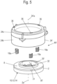
- Fig.5 shows a schematic exploded view of the first grinding disc carrier M1 with the first grinding disc 2 of the grinding mechanism 1 according to the invention according to Figure 2 .
- Fig.6 is the view Fig.5 rotated by 180° around an axis perpendicular to the drawing.
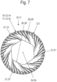
- Fig.7 shows a schematic plan view of the grinding side 10, 11 of the grinding disc 2, 3.
- Fig.8 a schematic perspective view of the grinding side 10, 11 of the grinding disc 2, 3 is shown; a schematic perspective view of the rear side 8, 9 of the grinding disc 2, 3 shows Fig.9 .
- Fig.10 represents a schematic sectional view of the grinding disc 2, 3, and Fig. 11 shows an enlarged section XI of the Fig.10 with a nose 31, 31'.
- the upper or first grinding disc carrier M1 comprises the first grinding disc 2 with its grinding disc axis 2a, compression springs 18a and the carrier 24' with its carrier axis 24'a.
- the first grinding disk 2 is designed in the same way as the second grinding disk 3, i.e. both grinding disks 2, 3 are identical.
- the carrier 24' of the first grinding disk carrier M1 the inner contour 29', the contour surfaces 30' and the lugs 31' of the first grinding disk 2 are provided with an apostrophe.
- the first grinding disc 2 like the second grinding disc 3, has a central opening, which is referred to here as inner contour 29' and is formed with contour surfaces 30'.
- the first grinding disk 2 which is spring-loaded with the compression springs 18a, is inserted into the carrier 24', guided in the carrier 24' and clamped in a manner not shown.
- the grinding disk axis 2a of the first grinding disk 2 and the carrier axis 24'a of the carrier 24' run coaxially and, in the assembled state of the grinding mechanism 1, coaxially with the grinding mechanism axis 1a.
- the first grinding disk 2 is here permanently inserted, e.g. clipped, into a carrier insert 24c, e.g. a plastic carrier, including the pressure springs 18a for force control.
- the carrier insert 24c is inserted in a carrier base 24b of the carrier 24' in a manner not shown in detail and connected to it, e.g. via a snap-in/clip connection.
- the carrier 24' is here designed as a multi-part component with the carrier base 24b and the carrier insert 24c.
- the carrier 24' can also be in one piece with the carrier base 24b and the carrier insert 24c.
- the carrier 24' has a protruding contour projection 33 with outer contour surfaces 34 in its interior.
- the contour projection 33 corresponds to the inner contour 24' of the first grinding disk 2.
- the contour projection 33 of the first grinding disk carrier M1 is provided with a central opening 5a. This opening 5a extends or supplements the central opening 5 described above in order to allow the coffee beans 7 from the filling funnel 6 access to the grinding chamber 16 between the grinding disks 2, 3.
- the contour-integrated lugs 31' (snap lugs") advantageously formed on the circumference of the first grinding disk 2 ensure that the first grinding disk 2 is axially secured in the carrier 24' of the first grinding disk carrier M1.
- the first grinding disk 2 is clipped into the carrier insert 24c, e.g. plastic carrier, in such a way that the lugs 31' are each slidably guided in a groove 35 of the carrier insert 24c.
- the grooves 35 run parallel to the carrier axis 24'a of the carrier 24 and each have a projection 36 at their lower ends, which forms an axial stop for a stop surface 31'a of the respective lug 31' guided in the associated groove 35. In this way, the first grinding disk 2 is axially secured in the carrier insert 24c of the carrier 24.
- the compression springs 18a are located between the rear side 8 of the first grinding disc 2 and are supported in a manner not shown but easily imaginable on the associated support sections of the support base 24b of the support 24'.
- the compression springs 18a are symmetrical about the grinding disc axis 2a and about the grinding mechanism axis 1a in order to achieve an optimally distributed force application. However, more than the three compression springs 18a shown can also be provided.
- a helical spring is preferred as the compression spring 18a for this application.
- springs or spring assemblies of other designs can also be used.
- the first grinding disk 2 thus has an axial degree of freedom in the direction of its grinding disk axis 2a, i.e. in the direction of the support axis 24'a and the grinding mechanism axis 1a of the grinding mechanism 1. This will be explained in more detail below.
- the snap geometry (noses 31' and projections 36) can be made very delicate. Due to this structural design, it is possible to design the lower and upper grinding disks 2, 3 as identical parts.
- Fig.7-9 the design of the inner contour 29, 29' with the contour surfaces 30, 30' is shown as a hexagon with rounded corners.
- Other form-fitting contours are of course possible, such as square, polygonal, oval, ellipse, etc.
- the inner contour 30 of the second grinding disk 3 is sealed tightly in the inserted state (see Fig.4 ) that no coffee grounds can accumulate in this area and that easy cleaning is possible.
- the inner contour 29, 29' is formed continuously into the grinding disc 2, 3, also through the annular projection 32, 32', as in Fig.9 is clearly visible.
- the lugs 31, 31' protrude radially on the outer circumference of the grinding disk 2, 3 at the edge of the rear side 8, 9.
- the lugs 31, 31' widen from the rear side 8, 9 to a stop surface 31a, 31'a in an axial direction relative to the grinding disk axis 2a, 3a. This is in Fig. 11 shown enlarged.
- Fig. 12-14 show schematic sectional views of the first grinding disc 2 according to Figure 7-9 in different stroke positions in relation to the corresponding contour projection 33 of the first grinding disk carrier M1.
- the first grinding disk 2 has an axial length L in the direction of the grinding disk axis 2a, ie in the direction of the carrier axis 24'a.
- a length 33a of the contour projection 33 in the direction of the carrier axis 24'a is here greater than the axial length L of the first grinding disk 2.
- the surface of the ring projection 32' serves as a stroke reference HR for further considerations.
- a relative stroke H1 of the grinding disk 2 in relation to the stroke reference HR results.
- this relative stroke H1 is slightly larger than an axial length of the ring projection 32'.
- the first grinding disk 2 thus has an axial degree of freedom in the direction of the axes 2a; 24'a.
- This axial degree of freedom of the first grinding disc 2 with respect to the contour projection 33 also makes it possible to achieve a relative stroke H2 greater than the axial length L of the first grinding disc 2.
- the inner contour 29' of the first grinding disk 2 is completely pushed onto the contour projection 33a and the contour projection 33a protrudes through the inner contour 29' from the area of the grinding blades 14. This position can also be used to clean the recess 13 in the grinding blades 14.
- a limitation of the stroke of the first grinding disk 2 with respect to the contour projection 33 can be realized, for example, by a stop of the first grinding disk 2 with the stroke reference HR on a stop (not shown) in the carrier 24.
- the torque for the grinding disc 2, 3, here the second grinding disc 3, is transmitted via the positive connection of the contour 25 of the carrier 24 and the inner contour 29, 29' at the inner passage of the grinding disc 2, 3.
- This positive connection is a centric positive connection as a continuous shaft-hub connection for the immediate torque transmission from the drive directly or indirectly to the grinding disc 2, 3.
- the A centric form fit exists between the contour 25 of the contour projection 33 of the carrier 24 and the inner contour 29, 29' of the grinding disk 2, 3.
- the grinding disks 2, 3 are made of one piece.
- the form fit is achieved directly via the geometric shape of the inner contour 29 of the grinding disk 3, e.g. as described above as a hexagonal contour.
- a hexagonal contour has smooth walls and has no grooves. Additional and/or intermediate components, such as feather keys etc., are therefore not required. This significantly minimizes the places where coffee grounds can settle.
- first grinding disc 2 is inserted into the first grinding disc carrier 24' without springs 18a.
Landscapes
- Engineering & Computer Science (AREA)
- Food Science & Technology (AREA)
- Mechanical Engineering (AREA)
- Crushing And Grinding (AREA)
- Polishing Bodies And Polishing Tools (AREA)
- Adjustment And Processing Of Grains (AREA)
Claims (15)
- Broyeur (1) pour broyer des grains de café (5), le broyeur (1) présentant un premier support de disque de broyage (M1) avec un premier disque de broyage (2), un second support de disque de broyage (M2) avec un second disque de broyage (3) et une unité d'entraînement (4), au moyen de laquelle au moins l'un des deux disques de broyage (2, 3) est mis en rotation, au moins ledit disque de broyage (3) des deux disques de broyage (2, 3) qui est mis en rotation au moyen de l'unité d'entraînement (4) étant accouplé directement ou indirectement à l'unité d'entraînement (4) au moyen d'une liaison de verrouillage central, ladite liaison de verrouillage central étant réalisée sous la forme d'une liaison arbre-moyeu pour un transfert de couple direct de l'unité d'entraînement (4) directement ou indirectement au disque de broyage (2, 3), caractérisé en ce que le premier disque de broyage (2) des deux disques de broyage (2, 3) s'engage par verrouillage, par son contour intérieur central (29'), avec une saillie de contour centrale (33) d'un support (24') du premier support de disque de broyage (M1) et que cette liaison de verrouillage central est réalisée sous la forme d'une liaison arbre-moyeu continue.
- Broyeur (1) selon la revendication 1, caractérisé en ce qu'au moins l'un des deux disques de broyage (2, 3) ou les deux disques de broyage (2, 3) présentent une brèche avec un contour intérieur central (29, 29').
- Broyeur (1) selon la revendication 2, caractérisé en ce que ledit disque de broyage (3) des deux disques de broyage (2, 3) qui est mis en rotation au moyen de l'unité d'entraînement (4) s'engage par verrouillage, par sa brèche avec le contour intérieur central (29), avec un contour central (25) d'un support (24) du second support de disque de broyage (M2), le support (24) étant relié à un arbre d'entraînement (21) de l'unité d'entraînement (4).
- Broyeur (1) selon la revendication 3, caractérisé en ce que le support (24) du second support de disque de broyage (M2) présente une section annulaire (26) disposée autour du contour central (25).
- Broyeur (1) selon la revendication 4, caractérisé en ce que le support (24) du second support de disque de broyage (M2) présente un espace libre (26a) défini par la section annulaire (26) et le contour central (25).
- Broyeur (1) selon l'une des revendications précédentes, caractérisé en ce que la saillie de contour (33) du support (24') du premier support de disque de broyage (M1) présente une brèche centrale (5a).
- Broyeur (1) selon l'une des revendications précédentes, caractérisé en ce que les deux disques de broyage (2, 3) présentent chacun des ergots (31, 31') en saillie radiale, formés sur les circonférences extérieures des deux disques de broyage (2, 3), répartis régulièrement.
- Broyeur (1) selon la revendication 7, caractérisé en ce que le premier disque de broyage (2) des deux disques de broyage (2, 3) est inséré dans un support (24') du premier support de disque de broyage (M1) et est guidé axialement dans le support (24') et est bloqué axialement au moyen des ergots (31').
- Broyeur (1) selon la revendication 8, caractérisé en ce que le premier disque de broyage (2) des deux disques de broyage (2, 3) est inséré dans le support (24') du premier support de disque de broyage (M1) de telle sorte que les ergots (31') sont guidés chacun de manière coulissant axialement dans une rainure (35) et sont logés de manière à être bloqués axialement.
- Broyeur (1) selon l'une des revendications précédentes, caractérisé en ce que des saillies en forme de languettes (27) sont disposées sur la circonférence extérieure de la section annulaire (26) du support (24) du second support de disque de broyage (M2), réparties régulièrement, qui font saillie de la section annulaire (26) du support (24) du second support de disque de broyage (M2), les saillies en forme de languettes (27) présentant chacune un évidement formé (28) qui s'engage avec un ergot respectif (31) du second disque de broyage (3) des deux disques de broyage (2, 3) qui est mis en rotation au moyen de l'unité d'entraînement (4).
- Broyeur (1) selon l'une des revendications précédentes, caractérisé en ce que le broyeur (1) est réalisé sous forme de broyeur à disques.
- Broyeur (1) selon l'une des revendications précédentes, caractérisé en ce que les contours intérieurs centraux (29, 29') des deux disques de broyage (2, 3), la saillie de contour (33) du support (24') du premier support de disque de broyage (M1) et le contour central (25) du support (24) du second support de disque de broyage (M2) ont la forme de polygones, de préférence d'hexagones, de triangles, de carrés, d'ovales, d'ellipses et similaires, le contour intérieur central (29') du premier disque de broyage (2) des deux disques de broyage (2, 3) et la saillie de contour (33) du support (24') du premier support de disque de broyage (M1) correspondant entre eux, et dans lequel le contour intérieur central (29) du second disque de broyage (3) des deux disques de broyage (2, 3), qui est mis en rotation au moyen de l'unité d'entraînement (4), et le contour central (25) du support (24) du second support de disque de broyage (M2) correspondent entre eux.
- Broyeur (1) selon l'une des revendications précédentes, caractérisé en ce que les deux disques de broyage (2, 3) sont identiques.
- Disques de broyage (2, 3) pour un broyeur (1) selon l'une des revendications précédentes, les deux disques de broyage (2, 3) présentant chacun une brèche avec un contour intérieur central (29, 29'), caractérisés en ce que les deux disques de broyage (2, 3) présentent chacun des ergots (31, 31') en saillie radiale, qui sont formés sur les circonférences extérieures des deux disques de broyage (2, 3), respectivement répartis régulièrement.
- Machine à café, en particulier machine à café automatique avec au moins un broyeur (1) selon l'une des revendications 1 à 13.
Applications Claiming Priority (2)
| Application Number | Priority Date | Filing Date | Title |
|---|---|---|---|
| DE102019134875 | 2019-12-18 | ||
| PCT/EP2020/086360 WO2021122700A1 (fr) | 2019-12-18 | 2020-12-16 | Broyeur, disque de broyage pour un broyeur et machine à café équipée d'un tel broyeur |
Publications (2)
| Publication Number | Publication Date |
|---|---|
| EP4076114A1 EP4076114A1 (fr) | 2022-10-26 |
| EP4076114B1 true EP4076114B1 (fr) | 2024-08-21 |
Family
ID=74141460
Family Applications (1)
| Application Number | Title | Priority Date | Filing Date |
|---|---|---|---|
| EP20838388.5A Active EP4076114B1 (fr) | 2019-12-18 | 2020-12-16 | Broyeur, disque de broyage pour un broyeur et machine à café équipée d'un tel broyeur |
Country Status (5)
| Country | Link |
|---|---|
| US (1) | US12458172B2 (fr) |
| EP (1) | EP4076114B1 (fr) |
| JP (1) | JP7422879B2 (fr) |
| CN (1) | CN114786548B (fr) |
| WO (1) | WO2021122700A1 (fr) |
Families Citing this family (2)
| Publication number | Priority date | Publication date | Assignee | Title |
|---|---|---|---|---|
| KR102307956B1 (ko) * | 2020-09-18 | 2021-10-01 | 유인오 | 분쇄 균일성을 위한 버 얼라인먼트 정밀도가 향상된 커피 그라인더 |
| CN121335652A (zh) * | 2023-09-12 | 2026-01-13 | 咖爷科技(苏州)有限公司 | 一种研磨刀盘及其制备方法、研磨装置、饮品冲调设备 |
Citations (1)
| Publication number | Priority date | Publication date | Assignee | Title |
|---|---|---|---|---|
| EP2956039B1 (fr) * | 2013-02-14 | 2017-05-24 | Ideas Denmark A/S | Unité de broyage, cartouche pour l'unité de broyage et utilisation de celle-ci pour broyer des grains de café |
Family Cites Families (17)
| Publication number | Priority date | Publication date | Assignee | Title |
|---|---|---|---|---|
| CH262751A (de) * | 1948-07-22 | 1949-07-31 | Ag Saturn | Haushaltungsmaschine. |
| DE8802375U1 (de) | 1988-02-24 | 1988-06-16 | Jupiter GmbH Küchenmaschinenfabrik, 73614 Schorndorf | Mahlscheibe für ein Mahlwerk einer Mühle, insbesondere Haushalt-Getreidemühle |
| ES2250957T3 (es) | 2003-06-30 | 2006-04-16 | Saeco Ipr Limited | Molinillo de cafe para cafetera. |
| DE202006003760U1 (de) | 2006-03-09 | 2006-06-08 | BSH Bosch und Siemens Hausgeräte GmbH | Mahlwerk für eine Kaffeemaschine |
| DE202007016141U1 (de) * | 2006-11-17 | 2008-02-28 | Ditting Maschinen Ag | Mahlwerk |
| EP2050377A1 (fr) | 2007-10-16 | 2009-04-22 | Eldom Rothrist AG | Outil de meulage |
| US7604192B2 (en) | 2007-11-28 | 2009-10-20 | Samson Bright Industrial Company Limited | Grinding apparatus for a condiment grinder |
| KR101109768B1 (ko) * | 2008-11-25 | 2012-02-15 | 유일시스템 주식회사 | 그라인더 유니트 |
| DE102010017721A1 (de) | 2010-07-05 | 2010-12-30 | SEVERIN ELEKTROGERÄTE GmbH | Mahlwerk |
| DE102011076247A1 (de) * | 2011-05-20 | 2012-11-22 | BSH Bosch und Siemens Hausgeräte GmbH | Vorratsbehälter für Kaffeebohnen |
| CH708196B1 (de) | 2013-06-06 | 2017-05-15 | Steiner Ag Weggis | Kaffeemühle, insbesondere für eine automatische Kaffeemaschine. |
| US10239062B2 (en) | 2013-08-05 | 2019-03-26 | Sharp Kabushiki Kaisha | Mill and beverage preparation apparatus including the same |
| PT3114975T (pt) * | 2015-07-10 | 2018-12-05 | Jura Elektroapparate Ag | Moedor para máquina de café |
| CN105167615B (zh) * | 2015-09-15 | 2017-11-28 | 广东新宝电器股份有限公司 | 一种咖啡机磨豆系统 |
| US10405700B2 (en) * | 2016-03-09 | 2019-09-10 | Chung-Jen Pai | Grinder |
| JP6823447B2 (ja) * | 2016-12-15 | 2021-02-03 | ツインバード工業株式会社 | ミル刃及びミル装置 |
| IT201800003924A1 (it) * | 2018-03-26 | 2019-09-26 | De Longhi Appliances Srl | Macinino per macchina da caffè automatica |
-
2020
- 2020-12-16 EP EP20838388.5A patent/EP4076114B1/fr active Active
- 2020-12-16 WO PCT/EP2020/086360 patent/WO2021122700A1/fr not_active Ceased
- 2020-12-16 CN CN202080087767.6A patent/CN114786548B/zh active Active
- 2020-12-16 JP JP2022537695A patent/JP7422879B2/ja active Active
- 2020-12-16 US US17/777,117 patent/US12458172B2/en active Active
Patent Citations (1)
| Publication number | Priority date | Publication date | Assignee | Title |
|---|---|---|---|---|
| EP2956039B1 (fr) * | 2013-02-14 | 2017-05-24 | Ideas Denmark A/S | Unité de broyage, cartouche pour l'unité de broyage et utilisation de celle-ci pour broyer des grains de café |
Also Published As
| Publication number | Publication date |
|---|---|
| JP2023514475A (ja) | 2023-04-06 |
| CN114786548A (zh) | 2022-07-22 |
| US20230355038A1 (en) | 2023-11-09 |
| JP7422879B2 (ja) | 2024-01-26 |
| EP4076114A1 (fr) | 2022-10-26 |
| US12458172B2 (en) | 2025-11-04 |
| CN114786548B (zh) | 2024-12-31 |
| WO2021122700A1 (fr) | 2021-06-24 |
Similar Documents
| Publication | Publication Date | Title |
|---|---|---|
| DE3718728C1 (de) | Raspel- oder Schneidwerkzeugsanordnung zum Zerkleinern von Nahrungsmitteln,insbesondere fuer Kuechenmaschinen | |
| DE102019122996A1 (de) | Mahlwerk und Kaffeemaschine mit einem solchen Mahlwerk | |
| EP3285626B1 (fr) | Couteau de mixeur plongeant à bord de fraisage | |
| EP2050377A1 (fr) | Outil de meulage | |
| EP2984973A1 (fr) | Broyeur de grains de café et machine à café dotée d'un tel broyeur | |
| WO2016169883A1 (fr) | Unité de travail pourvue d'une tige mobile de façon télescopique pour agiter ou broyer des aliments | |
| EP3964295B3 (fr) | Hachoir à viande | |
| EP3840620B1 (fr) | Moulin destiné au broyage de produit à broyer | |
| EP4076114B1 (fr) | Broyeur, disque de broyage pour un broyeur et machine à café équipée d'un tel broyeur | |
| EP3831494B1 (fr) | Broyeur à découper destiné au broyage par découpage des échantillons | |
| EP3106069B1 (fr) | Moulin à épices | |
| EP4240531A1 (fr) | Support en forme de croix pour hachoir à viande | |
| EP4146399B1 (fr) | Système de jeu à couper pour un hachoir à viande | |
| DE19513992C2 (de) | Axiale Fixierung einer Welle-Nabe-Verbindung | |
| DE102008013232A1 (de) | Vorrichtung zum Zerkleinern von Aufgabegut mit einem Rotor | |
| EP3958717B1 (fr) | Broyeur pourvu d'un élément de blocage | |
| WO2013171567A1 (fr) | Dispositif d'accouplement rotatif de deux ensembles | |
| DE19807790B4 (de) | Beidseitig wirkende Verstellvorrichtung | |
| EP1818100A1 (fr) | Appareil pour moudre des matériaux granuleux, en particulier dans le domaine alimentaire | |
| AT510147B1 (de) | Gewürzmühle mit einem mahlwerk | |
| EP2156772A1 (fr) | Broyeur destiné à broyer des aliments, en particulier du café | |
| EP2845649A1 (fr) | Dispositif de découpe | |
| EP4132332B1 (fr) | Moulin à épices réglable | |
| DE3146637C2 (de) | Vielzweck-Küchenmaschine mit motorischem Antrieb | |
| DE102012103209B4 (de) | Lebensmittelverarbeitendes Gerät |
Legal Events
| Date | Code | Title | Description |
|---|---|---|---|
| STAA | Information on the status of an ep patent application or granted ep patent |
Free format text: STATUS: UNKNOWN |
|
| STAA | Information on the status of an ep patent application or granted ep patent |
Free format text: STATUS: THE INTERNATIONAL PUBLICATION HAS BEEN MADE |
|
| PUAI | Public reference made under article 153(3) epc to a published international application that has entered the european phase |
Free format text: ORIGINAL CODE: 0009012 |
|
| STAA | Information on the status of an ep patent application or granted ep patent |
Free format text: STATUS: REQUEST FOR EXAMINATION WAS MADE |
|
| 17P | Request for examination filed |
Effective date: 20220705 |
|
| AK | Designated contracting states |
Kind code of ref document: A1 Designated state(s): AL AT BE BG CH CY CZ DE DK EE ES FI FR GB GR HR HU IE IS IT LI LT LU LV MC MK MT NL NO PL PT RO RS SE SI SK SM TR |
|
| DAV | Request for validation of the european patent (deleted) | ||
| DAX | Request for extension of the european patent (deleted) | ||
| GRAP | Despatch of communication of intention to grant a patent |
Free format text: ORIGINAL CODE: EPIDOSNIGR1 |
|
| STAA | Information on the status of an ep patent application or granted ep patent |
Free format text: STATUS: GRANT OF PATENT IS INTENDED |
|
| INTG | Intention to grant announced |
Effective date: 20240510 |
|
| GRAS | Grant fee paid |
Free format text: ORIGINAL CODE: EPIDOSNIGR3 |
|
| GRAA | (expected) grant |
Free format text: ORIGINAL CODE: 0009210 |
|
| STAA | Information on the status of an ep patent application or granted ep patent |
Free format text: STATUS: THE PATENT HAS BEEN GRANTED |
|
| P01 | Opt-out of the competence of the unified patent court (upc) registered |
Free format text: CASE NUMBER: APP_39666/2024 Effective date: 20240703 |
|
| AK | Designated contracting states |
Kind code of ref document: B1 Designated state(s): AL AT BE BG CH CY CZ DE DK EE ES FI FR GB GR HR HU IE IS IT LI LT LU LV MC MK MT NL NO PL PT RO RS SE SI SK SM TR |
|
| REG | Reference to a national code |
Ref country code: GB Ref legal event code: FG4D Free format text: NOT ENGLISH |
|
| REG | Reference to a national code |
Ref country code: CH Ref legal event code: EP |
|
| REG | Reference to a national code |
Ref country code: DE Ref legal event code: R096 Ref document number: 502020008979 Country of ref document: DE |
|
| REG | Reference to a national code |
Ref country code: IE Ref legal event code: FG4D Free format text: LANGUAGE OF EP DOCUMENT: GERMAN |
|
| REG | Reference to a national code |
Ref country code: LT Ref legal event code: MG9D |
|
| REG | Reference to a national code |
Ref country code: NL Ref legal event code: MP Effective date: 20240821 |
|
| PG25 | Lapsed in a contracting state [announced via postgrant information from national office to epo] |
Ref country code: NO Free format text: LAPSE BECAUSE OF FAILURE TO SUBMIT A TRANSLATION OF THE DESCRIPTION OR TO PAY THE FEE WITHIN THE PRESCRIBED TIME-LIMIT Effective date: 20241121 |
|
| PG25 | Lapsed in a contracting state [announced via postgrant information from national office to epo] |
Ref country code: NL Free format text: LAPSE BECAUSE OF FAILURE TO SUBMIT A TRANSLATION OF THE DESCRIPTION OR TO PAY THE FEE WITHIN THE PRESCRIBED TIME-LIMIT Effective date: 20240821 Ref country code: PL Free format text: LAPSE BECAUSE OF FAILURE TO SUBMIT A TRANSLATION OF THE DESCRIPTION OR TO PAY THE FEE WITHIN THE PRESCRIBED TIME-LIMIT Effective date: 20240821 Ref country code: GR Free format text: LAPSE BECAUSE OF FAILURE TO SUBMIT A TRANSLATION OF THE DESCRIPTION OR TO PAY THE FEE WITHIN THE PRESCRIBED TIME-LIMIT Effective date: 20241122 Ref country code: FI Free format text: LAPSE BECAUSE OF FAILURE TO SUBMIT A TRANSLATION OF THE DESCRIPTION OR TO PAY THE FEE WITHIN THE PRESCRIBED TIME-LIMIT Effective date: 20240821 Ref country code: PT Free format text: LAPSE BECAUSE OF FAILURE TO SUBMIT A TRANSLATION OF THE DESCRIPTION OR TO PAY THE FEE WITHIN THE PRESCRIBED TIME-LIMIT Effective date: 20241223 |
|
| PG25 | Lapsed in a contracting state [announced via postgrant information from national office to epo] |
Ref country code: BG Free format text: LAPSE BECAUSE OF FAILURE TO SUBMIT A TRANSLATION OF THE DESCRIPTION OR TO PAY THE FEE WITHIN THE PRESCRIBED TIME-LIMIT Effective date: 20240821 |
|
| PG25 | Lapsed in a contracting state [announced via postgrant information from national office to epo] |
Ref country code: LV Free format text: LAPSE BECAUSE OF FAILURE TO SUBMIT A TRANSLATION OF THE DESCRIPTION OR TO PAY THE FEE WITHIN THE PRESCRIBED TIME-LIMIT Effective date: 20240821 |
|
| PG25 | Lapsed in a contracting state [announced via postgrant information from national office to epo] |
Ref country code: IS Free format text: LAPSE BECAUSE OF FAILURE TO SUBMIT A TRANSLATION OF THE DESCRIPTION OR TO PAY THE FEE WITHIN THE PRESCRIBED TIME-LIMIT Effective date: 20241221 |
|
| PG25 | Lapsed in a contracting state [announced via postgrant information from national office to epo] |
Ref country code: HR Free format text: LAPSE BECAUSE OF FAILURE TO SUBMIT A TRANSLATION OF THE DESCRIPTION OR TO PAY THE FEE WITHIN THE PRESCRIBED TIME-LIMIT Effective date: 20240821 |
|
| PG25 | Lapsed in a contracting state [announced via postgrant information from national office to epo] |
Ref country code: ES Free format text: LAPSE BECAUSE OF FAILURE TO SUBMIT A TRANSLATION OF THE DESCRIPTION OR TO PAY THE FEE WITHIN THE PRESCRIBED TIME-LIMIT Effective date: 20240821 Ref country code: RS Free format text: LAPSE BECAUSE OF FAILURE TO SUBMIT A TRANSLATION OF THE DESCRIPTION OR TO PAY THE FEE WITHIN THE PRESCRIBED TIME-LIMIT Effective date: 20241121 |
|
| PG25 | Lapsed in a contracting state [announced via postgrant information from national office to epo] |
Ref country code: RS Free format text: LAPSE BECAUSE OF FAILURE TO SUBMIT A TRANSLATION OF THE DESCRIPTION OR TO PAY THE FEE WITHIN THE PRESCRIBED TIME-LIMIT Effective date: 20241121 Ref country code: PT Free format text: LAPSE BECAUSE OF FAILURE TO SUBMIT A TRANSLATION OF THE DESCRIPTION OR TO PAY THE FEE WITHIN THE PRESCRIBED TIME-LIMIT Effective date: 20241223 Ref country code: PL Free format text: LAPSE BECAUSE OF FAILURE TO SUBMIT A TRANSLATION OF THE DESCRIPTION OR TO PAY THE FEE WITHIN THE PRESCRIBED TIME-LIMIT Effective date: 20240821 Ref country code: NO Free format text: LAPSE BECAUSE OF FAILURE TO SUBMIT A TRANSLATION OF THE DESCRIPTION OR TO PAY THE FEE WITHIN THE PRESCRIBED TIME-LIMIT Effective date: 20241121 Ref country code: NL Free format text: LAPSE BECAUSE OF FAILURE TO SUBMIT A TRANSLATION OF THE DESCRIPTION OR TO PAY THE FEE WITHIN THE PRESCRIBED TIME-LIMIT Effective date: 20240821 Ref country code: LV Free format text: LAPSE BECAUSE OF FAILURE TO SUBMIT A TRANSLATION OF THE DESCRIPTION OR TO PAY THE FEE WITHIN THE PRESCRIBED TIME-LIMIT Effective date: 20240821 Ref country code: IS Free format text: LAPSE BECAUSE OF FAILURE TO SUBMIT A TRANSLATION OF THE DESCRIPTION OR TO PAY THE FEE WITHIN THE PRESCRIBED TIME-LIMIT Effective date: 20241221 Ref country code: HR Free format text: LAPSE BECAUSE OF FAILURE TO SUBMIT A TRANSLATION OF THE DESCRIPTION OR TO PAY THE FEE WITHIN THE PRESCRIBED TIME-LIMIT Effective date: 20240821 Ref country code: GR Free format text: LAPSE BECAUSE OF FAILURE TO SUBMIT A TRANSLATION OF THE DESCRIPTION OR TO PAY THE FEE WITHIN THE PRESCRIBED TIME-LIMIT Effective date: 20241122 Ref country code: FI Free format text: LAPSE BECAUSE OF FAILURE TO SUBMIT A TRANSLATION OF THE DESCRIPTION OR TO PAY THE FEE WITHIN THE PRESCRIBED TIME-LIMIT Effective date: 20240821 Ref country code: ES Free format text: LAPSE BECAUSE OF FAILURE TO SUBMIT A TRANSLATION OF THE DESCRIPTION OR TO PAY THE FEE WITHIN THE PRESCRIBED TIME-LIMIT Effective date: 20240821 Ref country code: BG Free format text: LAPSE BECAUSE OF FAILURE TO SUBMIT A TRANSLATION OF THE DESCRIPTION OR TO PAY THE FEE WITHIN THE PRESCRIBED TIME-LIMIT Effective date: 20240821 |
|
| PG25 | Lapsed in a contracting state [announced via postgrant information from national office to epo] |
Ref country code: DK Free format text: LAPSE BECAUSE OF FAILURE TO SUBMIT A TRANSLATION OF THE DESCRIPTION OR TO PAY THE FEE WITHIN THE PRESCRIBED TIME-LIMIT Effective date: 20240821 Ref country code: RO Free format text: LAPSE BECAUSE OF FAILURE TO SUBMIT A TRANSLATION OF THE DESCRIPTION OR TO PAY THE FEE WITHIN THE PRESCRIBED TIME-LIMIT Effective date: 20240821 Ref country code: SM Free format text: LAPSE BECAUSE OF FAILURE TO SUBMIT A TRANSLATION OF THE DESCRIPTION OR TO PAY THE FEE WITHIN THE PRESCRIBED TIME-LIMIT Effective date: 20240821 |
|
| PG25 | Lapsed in a contracting state [announced via postgrant information from national office to epo] |
Ref country code: EE Free format text: LAPSE BECAUSE OF FAILURE TO SUBMIT A TRANSLATION OF THE DESCRIPTION OR TO PAY THE FEE WITHIN THE PRESCRIBED TIME-LIMIT Effective date: 20240821 |
|
| PG25 | Lapsed in a contracting state [announced via postgrant information from national office to epo] |
Ref country code: CZ Free format text: LAPSE BECAUSE OF FAILURE TO SUBMIT A TRANSLATION OF THE DESCRIPTION OR TO PAY THE FEE WITHIN THE PRESCRIBED TIME-LIMIT Effective date: 20240821 |
|
| PG25 | Lapsed in a contracting state [announced via postgrant information from national office to epo] |
Ref country code: SK Free format text: LAPSE BECAUSE OF FAILURE TO SUBMIT A TRANSLATION OF THE DESCRIPTION OR TO PAY THE FEE WITHIN THE PRESCRIBED TIME-LIMIT Effective date: 20240821 |
|
| REG | Reference to a national code |
Ref country code: DE Ref legal event code: R097 Ref document number: 502020008979 Country of ref document: DE |
|
| PLBE | No opposition filed within time limit |
Free format text: ORIGINAL CODE: 0009261 |
|
| STAA | Information on the status of an ep patent application or granted ep patent |
Free format text: STATUS: NO OPPOSITION FILED WITHIN TIME LIMIT |
|
| PG25 | Lapsed in a contracting state [announced via postgrant information from national office to epo] |
Ref country code: MC Free format text: LAPSE BECAUSE OF FAILURE TO SUBMIT A TRANSLATION OF THE DESCRIPTION OR TO PAY THE FEE WITHIN THE PRESCRIBED TIME-LIMIT Effective date: 20240821 |
|
| 26N | No opposition filed |
Effective date: 20250522 |
|
| PG25 | Lapsed in a contracting state [announced via postgrant information from national office to epo] |
Ref country code: LU Free format text: LAPSE BECAUSE OF NON-PAYMENT OF DUE FEES Effective date: 20241216 |
|
| GBPC | Gb: european patent ceased through non-payment of renewal fee |
Effective date: 20241216 |
|
| PG25 | Lapsed in a contracting state [announced via postgrant information from national office to epo] |
Ref country code: SE Free format text: LAPSE BECAUSE OF FAILURE TO SUBMIT A TRANSLATION OF THE DESCRIPTION OR TO PAY THE FEE WITHIN THE PRESCRIBED TIME-LIMIT Effective date: 20240821 |
|
| REG | Reference to a national code |
Ref country code: BE Ref legal event code: MM Effective date: 20241231 |
|
| PG25 | Lapsed in a contracting state [announced via postgrant information from national office to epo] |
Ref country code: BE Free format text: LAPSE BECAUSE OF NON-PAYMENT OF DUE FEES Effective date: 20241231 Ref country code: GB Free format text: LAPSE BECAUSE OF NON-PAYMENT OF DUE FEES Effective date: 20241216 |
|
| PG25 | Lapsed in a contracting state [announced via postgrant information from national office to epo] |
Ref country code: FR Free format text: LAPSE BECAUSE OF NON-PAYMENT OF DUE FEES Effective date: 20241231 |
|
| PG25 | Lapsed in a contracting state [announced via postgrant information from national office to epo] |
Ref country code: IE Free format text: LAPSE BECAUSE OF NON-PAYMENT OF DUE FEES Effective date: 20241216 |
|
| REG | Reference to a national code |
Ref country code: CH Ref legal event code: U11 Free format text: ST27 STATUS EVENT CODE: U-0-0-U10-U11 (AS PROVIDED BY THE NATIONAL OFFICE) Effective date: 20260101 |
|
| PGFP | Annual fee paid to national office [announced via postgrant information from national office to epo] |
Ref country code: AT Payment date: 20260113 Year of fee payment: 5 |
|
| PGFP | Annual fee paid to national office [announced via postgrant information from national office to epo] |
Ref country code: IT Payment date: 20251223 Year of fee payment: 6 |
|
| PGFP | Annual fee paid to national office [announced via postgrant information from national office to epo] |
Ref country code: DE Payment date: 20251231 Year of fee payment: 6 |
|
| PGFP | Annual fee paid to national office [announced via postgrant information from national office to epo] |
Ref country code: CH Payment date: 20260101 Year of fee payment: 6 |