EP4076230B1 - Universelle ritzvorrichtung - Google Patents
Universelle ritzvorrichtung Download PDFInfo
- Publication number
- EP4076230B1 EP4076230B1 EP20903837.1A EP20903837A EP4076230B1 EP 4076230 B1 EP4076230 B1 EP 4076230B1 EP 20903837 A EP20903837 A EP 20903837A EP 4076230 B1 EP4076230 B1 EP 4076230B1
- Authority
- EP
- European Patent Office
- Prior art keywords
- catheter
- scoring
- balloon
- socket
- retention sleeve
- Prior art date
- Legal status (The legal status is an assumption and is not a legal conclusion. Google has not performed a legal analysis and makes no representation as to the accuracy of the status listed.)
- Active
Links
Images







Classifications
-
- A—HUMAN NECESSITIES
- A61—MEDICAL OR VETERINARY SCIENCE; HYGIENE
- A61B—DIAGNOSIS; SURGERY; IDENTIFICATION
- A61B17/00—Surgical instruments, devices or methods
- A61B17/32—Surgical cutting instruments
- A61B17/3205—Excision instruments
- A61B17/3207—Atherectomy devices working by cutting or abrading; Similar devices specially adapted for non-vascular obstructions
- A61B17/320725—Atherectomy devices working by cutting or abrading; Similar devices specially adapted for non-vascular obstructions with radially expandable cutting or abrading elements
-
- A—HUMAN NECESSITIES
- A61—MEDICAL OR VETERINARY SCIENCE; HYGIENE
- A61M—DEVICES FOR INTRODUCING MEDIA INTO, OR ONTO, THE BODY; DEVICES FOR TRANSDUCING BODY MEDIA OR FOR TAKING MEDIA FROM THE BODY; DEVICES FOR PRODUCING OR ENDING SLEEP OR STUPOR
- A61M25/00—Catheters; Hollow probes
- A61M25/01—Introducing, guiding, advancing, emplacing or holding catheters
- A61M25/0105—Steering means as part of the catheter or advancing means; Markers for positioning
- A61M25/0113—Mechanical advancing means, e.g. catheter dispensers
-
- A—HUMAN NECESSITIES
- A61—MEDICAL OR VETERINARY SCIENCE; HYGIENE
- A61M—DEVICES FOR INTRODUCING MEDIA INTO, OR ONTO, THE BODY; DEVICES FOR TRANSDUCING BODY MEDIA OR FOR TAKING MEDIA FROM THE BODY; DEVICES FOR PRODUCING OR ENDING SLEEP OR STUPOR
- A61M25/00—Catheters; Hollow probes
- A61M25/10—Balloon catheters
-
- A—HUMAN NECESSITIES
- A61—MEDICAL OR VETERINARY SCIENCE; HYGIENE
- A61M—DEVICES FOR INTRODUCING MEDIA INTO, OR ONTO, THE BODY; DEVICES FOR TRANSDUCING BODY MEDIA OR FOR TAKING MEDIA FROM THE BODY; DEVICES FOR PRODUCING OR ENDING SLEEP OR STUPOR
- A61M25/00—Catheters; Hollow probes
- A61M25/10—Balloon catheters
- A61M25/1011—Multiple balloon catheters
-
- A—HUMAN NECESSITIES
- A61—MEDICAL OR VETERINARY SCIENCE; HYGIENE
- A61B—DIAGNOSIS; SURGERY; IDENTIFICATION
- A61B17/00—Surgical instruments, devices or methods
- A61B2017/00477—Coupling
-
- A—HUMAN NECESSITIES
- A61—MEDICAL OR VETERINARY SCIENCE; HYGIENE
- A61B—DIAGNOSIS; SURGERY; IDENTIFICATION
- A61B17/00—Surgical instruments, devices or methods
- A61B2017/00526—Methods of manufacturing
-
- A—HUMAN NECESSITIES
- A61—MEDICAL OR VETERINARY SCIENCE; HYGIENE
- A61B—DIAGNOSIS; SURGERY; IDENTIFICATION
- A61B17/00—Surgical instruments, devices or methods
- A61B2017/00831—Material properties
- A61B2017/00862—Material properties elastic or resilient
-
- A—HUMAN NECESSITIES
- A61—MEDICAL OR VETERINARY SCIENCE; HYGIENE
- A61B—DIAGNOSIS; SURGERY; IDENTIFICATION
- A61B17/00—Surgical instruments, devices or methods
- A61B17/22—Implements for squeezing-off ulcers or the like on inner organs of the body; Implements for scraping-out cavities of body organs, e.g. bones; for invasive removal or destruction of calculus using mechanical vibrations; for removing obstructions in blood vessels, not otherwise provided for
- A61B2017/22051—Implements for squeezing-off ulcers or the like on inner organs of the body; Implements for scraping-out cavities of body organs, e.g. bones; for invasive removal or destruction of calculus using mechanical vibrations; for removing obstructions in blood vessels, not otherwise provided for with an inflatable part, e.g. balloon, for positioning, blocking, or immobilisation
- A61B2017/22061—Implements for squeezing-off ulcers or the like on inner organs of the body; Implements for scraping-out cavities of body organs, e.g. bones; for invasive removal or destruction of calculus using mechanical vibrations; for removing obstructions in blood vessels, not otherwise provided for with an inflatable part, e.g. balloon, for positioning, blocking, or immobilisation for spreading elements apart
-
- A—HUMAN NECESSITIES
- A61—MEDICAL OR VETERINARY SCIENCE; HYGIENE
- A61B—DIAGNOSIS; SURGERY; IDENTIFICATION
- A61B17/00—Surgical instruments, devices or methods
- A61B17/32—Surgical cutting instruments
- A61B17/320016—Endoscopic cutting instruments, e.g. arthroscopes, resectoscopes
- A61B2017/32004—Endoscopic cutting instruments, e.g. arthroscopes, resectoscopes having a laterally movable cutting member at its most distal end which remains within the contours of said end
-
- A—HUMAN NECESSITIES
- A61—MEDICAL OR VETERINARY SCIENCE; HYGIENE
- A61M—DEVICES FOR INTRODUCING MEDIA INTO, OR ONTO, THE BODY; DEVICES FOR TRANSDUCING BODY MEDIA OR FOR TAKING MEDIA FROM THE BODY; DEVICES FOR PRODUCING OR ENDING SLEEP OR STUPOR
- A61M25/00—Catheters; Hollow probes
- A61M25/10—Balloon catheters
- A61M25/1011—Multiple balloon catheters
- A61M2025/1015—Multiple balloon catheters having two or more independently movable balloons where the distance between the balloons can be adjusted, e.g. two balloon catheters concentric to each other forming an adjustable multiple balloon catheter system
-
- A—HUMAN NECESSITIES
- A61—MEDICAL OR VETERINARY SCIENCE; HYGIENE
- A61M—DEVICES FOR INTRODUCING MEDIA INTO, OR ONTO, THE BODY; DEVICES FOR TRANSDUCING BODY MEDIA OR FOR TAKING MEDIA FROM THE BODY; DEVICES FOR PRODUCING OR ENDING SLEEP OR STUPOR
- A61M25/00—Catheters; Hollow probes
- A61M25/10—Balloon catheters
- A61M2025/1043—Balloon catheters with special features or adapted for special applications
- A61M2025/1081—Balloon catheters with special features or adapted for special applications having sheaths or the like for covering the balloon but not forming a permanent part of the balloon, e.g. retractable, dissolvable or tearable sheaths
-
- A—HUMAN NECESSITIES
- A61—MEDICAL OR VETERINARY SCIENCE; HYGIENE
- A61M—DEVICES FOR INTRODUCING MEDIA INTO, OR ONTO, THE BODY; DEVICES FOR TRANSDUCING BODY MEDIA OR FOR TAKING MEDIA FROM THE BODY; DEVICES FOR PRODUCING OR ENDING SLEEP OR STUPOR
- A61M25/00—Catheters; Hollow probes
- A61M25/10—Balloon catheters
- A61M2025/1043—Balloon catheters with special features or adapted for special applications
- A61M2025/1086—Balloon catheters with special features or adapted for special applications having a special balloon surface topography, e.g. pores, protuberances, spikes or grooves
-
- A—HUMAN NECESSITIES
- A61—MEDICAL OR VETERINARY SCIENCE; HYGIENE
- A61M—DEVICES FOR INTRODUCING MEDIA INTO, OR ONTO, THE BODY; DEVICES FOR TRANSDUCING BODY MEDIA OR FOR TAKING MEDIA FROM THE BODY; DEVICES FOR PRODUCING OR ENDING SLEEP OR STUPOR
- A61M25/00—Catheters; Hollow probes
- A61M25/10—Balloon catheters
- A61M2025/1043—Balloon catheters with special features or adapted for special applications
- A61M2025/109—Balloon catheters with special features or adapted for special applications having balloons for removing solid matters, e.g. by grasping or scraping plaque, thrombus or other matters that obstruct the flow
-
- A—HUMAN NECESSITIES
- A61—MEDICAL OR VETERINARY SCIENCE; HYGIENE
- A61M—DEVICES FOR INTRODUCING MEDIA INTO, OR ONTO, THE BODY; DEVICES FOR TRANSDUCING BODY MEDIA OR FOR TAKING MEDIA FROM THE BODY; DEVICES FOR PRODUCING OR ENDING SLEEP OR STUPOR
- A61M2205/00—General characteristics of the apparatus
- A61M2205/02—General characteristics of the apparatus characterised by a particular materials
- A61M2205/0216—Materials providing elastic properties, e.g. for facilitating deformation and avoid breaking
-
- A—HUMAN NECESSITIES
- A61—MEDICAL OR VETERINARY SCIENCE; HYGIENE
- A61M—DEVICES FOR INTRODUCING MEDIA INTO, OR ONTO, THE BODY; DEVICES FOR TRANSDUCING BODY MEDIA OR FOR TAKING MEDIA FROM THE BODY; DEVICES FOR PRODUCING OR ENDING SLEEP OR STUPOR
- A61M2207/00—Methods of manufacture, assembly or production
-
- A—HUMAN NECESSITIES
- A61—MEDICAL OR VETERINARY SCIENCE; HYGIENE
- A61M—DEVICES FOR INTRODUCING MEDIA INTO, OR ONTO, THE BODY; DEVICES FOR TRANSDUCING BODY MEDIA OR FOR TAKING MEDIA FROM THE BODY; DEVICES FOR PRODUCING OR ENDING SLEEP OR STUPOR
- A61M25/00—Catheters; Hollow probes
- A61M25/002—Packages specially adapted therefor ; catheter kit packages
-
- A—HUMAN NECESSITIES
- A61—MEDICAL OR VETERINARY SCIENCE; HYGIENE
- A61M—DEVICES FOR INTRODUCING MEDIA INTO, OR ONTO, THE BODY; DEVICES FOR TRANSDUCING BODY MEDIA OR FOR TAKING MEDIA FROM THE BODY; DEVICES FOR PRODUCING OR ENDING SLEEP OR STUPOR
- A61M25/00—Catheters; Hollow probes
- A61M25/10—Balloon catheters
- A61M25/104—Balloon catheters used for angioplasty
Definitions
- This document pertains generally, but not by way of limitation, to a scoring device configured to receive a catheter.
- a catheter is coupled with a scoring device.
- the scoring device is bonded to a balloon of the catheter, and the scoring device is provided as a unitary assembly.
- the catheter shaft is coupled (e.g., attached, glued, fused, or the like) with the catheter socket.
- each of the balloon, catheter, and cage have a specified size, or the like according to the particulars of the health care provider or application for the scoring device.
- WO2019234659A2 and US20170065796A1 each disclose cutting/scoring devices in the form of sleeves arranged to receive a main elongated medical instrument element such as a catheter.
- the invention is a scoring device as defined in the appended claims.
- a problem to be solved can include attaching catheters of varying profiles to a scoring device.
- the scoring device is coupled to a corresponding cage.
- a balloon catheter having a specified length and balloon profile is coupled with a cage having a specified profile. Accordingly, the balloon catheter is not separable from the cage.
- variations in length of the catheter (and characteristics of the balloon) are optionally needed based on different medical procedures, vascular locations, patient-specific anatomical variations, or the like.
- the present subject matter can help provide a solution to this problem, such as by a scoring device that is interchangeable with a plurality of catheters, each of the plurality of catheters optionally having a different profile.
- a scoring device that is interchangeable with a plurality of catheters, each of the plurality of catheters optionally having a different profile.
- a single or limited number of the scoring devices is maintained on hand by a healthcare provider.
- the present subject matter allows a healthcare provider to retain a variety of catheters (with varying profiles) on hand for a variety of procedures, vessel locations or the like.
- scoring is specified to assist with treatment of vasculature, one or a limited number of scoring devices are ready for marriage with the plurality of catheters as needed.
- the present subject matter minimizes the number of unique catheters needed while at the same time providing enhanced flexibility of selection and marriage, for example by allowing the physician to select catheters as specified (e.g., from any number of brands, sizes or the like) and then marrying the selected catheter to the scoring device described herein.
- the scoring device is configured to retain a catheter shaft.
- the scoring device includes a proximal portion and a distal portion.
- the distal portion includes a distal tip.
- the scoring device includes a retention sleeve extending between the proximal portion and the distal portion.
- the retention sleeve includes a catheter socket configured to selectively receive the catheter shaft. For instance, the catheter socket mechanically engages the catheter shaft while the catheter shaft is received in the catheter socket. Accordingly, the scoring device retains the catheter shaft within the catheter socket.
- the catheter socket of the scoring device selectively receives the catheter shaft.
- the catheter shaft is affixed (e.g., attached, glued, fused, or the like) with the catheter socket and the catheter shaft is not separable from the catheter socket.
- the selective reception of the catheter shaft by the catheter socket of the scoring device facilitates loading and separation of the catheter shaft from the scoring device.
- the catheter socket interchangeably receives one or more catheter shafts.
- the catheter socket interchangeably receives a first catheter shaft having a first profile, and a second catheter shaft having a second profile (different than the first profile).
- the scoring device interchangeably retains one or more catheter shafts.
- catheters of varying profiles are attached to the scoring device.
- the scoring device includes a deformable catheter port.
- the deformable catheter port is elastically deformable, for example to receive the catheter shaft.
- the catheter socket may selectively receive the catheter shaft through the deformable catheter port.
- the catheter port extends between an exterior of the retention sleeve and the catheter socket.
- the catheter port receives catheter shafts of varying profiles (e.g., a first catheter shaft having a first size, and a second catheter shaft having a second size) because the catheter port is elastically deformable and the elastic deformation permits the catheter port (and the catheter socket) to receive and accommodate catheter shafts of varying profiles.
- the scoring device includes a scoring tool.
- the scoring tool is coupled with the retention sleeve proximate to the distal portion.
- the scoring tool includes a balloon socket that selectively receives a balloon of the catheter shaft.
- the scoring tool includes one or more scoring elements.
- the scoring elements are directed away from the balloon socket.
- the scoring elements provide localized scoring to vasculature when deployed with a loaded balloon that is inflated. For instance, the scoring elements mechanically deform plaque within a vein, for instance to facilitate removal of the plaque.
- the balloon socket selectively receives a balloon of the catheter shaft.
- the balloon includes a deflated configuration and an inflated configuration.
- the balloon is expandable (e.g., enlargeable, growable, dilatable, stretchable, or the like) between the deflated and inflated configurations.
- a volume of the balloon is larger than the volume of the balloon in the deflated configuration.
- the scoring tool expands outward in conformity with the balloon (with the balloon located in the balloon socket).
- the scoring tool includes an initial configuration and an expanded configuration.
- expansion of the balloon facilitates transition of the scoring tool between the initial configuration and the expanded configuration.
- expansion of the balloon engages the balloon with the scoring tool and expands the scoring tool.
- the scoring tool expands in conformity with the balloon. Accordingly, in an example, transitioning of the balloon between deflated and inflated configurations correspondingly transitions the scoring tool between initial and expanded configurations.
- the balloon socket selectively receives the balloon, for instance because the catheter is separate from the scoring device and loaded into the scoring device.
- the balloon socket selectively receives a balloon of a first catheter having a first profile.
- the first catheter includes a first catheter shaft having a first balloon, the first balloon having a first expanded volume.
- the first catheter is optionally interchanged with a second catheter, for instance by separating the first catheter from the scoring device.
- the second catheter has a second profile.
- the second catheter includes a second catheter shaft having a second balloon with a second expanded volume.
- the scoring device retains the second catheter shaft (e.g., with the retention sleeve selectively receiving and mechanically engaging the second catheter shaft), and the balloon socket selectively receives the second balloon.
- the scoring device is interchangeable with a plurality of catheters, each of the plurality of catheters optionally having a different profile.
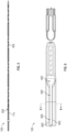
- FIG. 1 illustrates a side view of an example scoring device 100.
- the scoring device 100 includes a proximal portion 102 and a distal portion 104.
- the distal portion 104 includes a distal tip 106.
- the scoring device 100 includes a scoring tool 108.
- the scoring tool 108 is coupled proximate to the distal portion 104 of the scoring device 100.
- the scoring tool 108 includes one or more scoring elements 110, for instance a first scoring element 110A.
- the one or more scoring elements 110 provide localized scoring (e.g., scraping, scratching, deforming, dislodging, cutting, shaving, parting, dividing, macerating, or the like) to vasculature.
- the scoring elements 110 facilitate removal of matter (such as plaque) from vasculature of a patient.
- the scoring elements 110 score the matter (e.g., plaque, or the like) to facilitate dilation of a vessel and the matter or, in another example, to facilitate separation of the matter from the vasculature.
- the scoring tool 108 facilitates dilation (e.g., compression), removal of matter from the vasculature by scoring the matter with the scoring elements 110.
- the scoring tool 108 includes a plurality of sections 112.
- the scoring tool 108 includes a first section 112A, a second section 112B, and a third section 112C,
- the sections 112 have different profiles from other sections 112.
- the first section 112A includes a first scoring element profile (e.g., an elliptical profile, semicircular profile, elongate profile or the like) and the second section 112B includes a second scoring element profile (e.g., a helical profile, a screw profile, or the like).
- the scoring device 100 includes a retention sleeve 114.
- the retention sleeve 114 extends between the proximal portion 102 and the distal portion 104.
- the scoring device 100 retains a catheter shaft (e.g., the catheter shaft 202, shown in Figure 2 ).
- the retention sleeve 114 includes a catheter socket (e.g., the catheter socket 400, shown in Figure 4 ) that selectively receives and mechanically engages the catheter shaft to retain the catheter shaft in the retention sleeve 114 (and the scoring device 100).
- the scoring device 100 is configured to interchangeably fit and couple with various catheters to provide flexibility by marrying the scoring device 100 with various catheters selected by a physician.
- Figure 2 shows an example of a catheter 200.
- the catheter 200 includes a catheter shaft 202 and a balloon 204.
- the balloon 204 extends from the catheter shaft 202.
- Figure 2 shows the balloon in a deflated configuration.
- the balloon 204 is expandable between the deflated configuration and an inflated configuration (shown in Figure 3 ).
- the balloon 204 has a first balloon profile 206 (e.g., one or more of cross-section, shape, size, dimensions, contour, radius, perimeter, circumference, diameter, outline, boundary, configuration, pattern, arrangement, thickness, deployment from the catheter shaft 202, or the like).
- the balloon 204 has a first volume in the deflated configuration.
- the balloon 204 has a first characteristic 208 (e.g., length or the like).
- the balloon has a second characteristic 210 (e.g., a diameter, volume, cross-sectional area, shape, size, qualitative size relative to an inflated configuration or the like).
- the first characteristic 208 and the second characteristic 210 provides the balloon 204 with the first balloon profile 206 (and the first volume).
- the catheter 200 includes a proximal portion 212 and a distal portion 214.
- the balloon 204 is included in the distal portion 214 of the catheter 200.
- the distal tip 106 of the scoring device 100 receives the distal portion 214 of the catheter 200.
- the distal portion 214 of the catheter 200 includes distal coupling features 216, for example a balloon tip.
- the distal tip 106 of the scoring device 100 receives the distal coupling features 216 of the catheter 200.
- the distal portion 214 (and the distal coupling features 216) is optionally seated in the distal tip 106 of the scoring device 100. In an example, seating of the distal coupling features 216 aligns the distal portion 214 of the catheter 200 relative to the distal portion 104 of the scoring device 100.
- Figure 3 shows another side view of the catheter 200 of Figure 2 .
- the balloon 204 is expandable between the deflated configuration (shown in Figure 2 ) and an inflated configuration (shown in Figure 3 ).
- the balloon 204 has a second balloon profile 300.
- the second balloon profile 300 is larger than the first balloon profile 206 (e.g., by volume, cross sectional area, size, shape, deployment from the catheter shaft 202 or the like).
- the balloon 204 has a second volume in the inflated configuration, and the second volume is larger than the first volume of the balloon 204 in the deflated configuration.
- the balloon 204 in the inflated configuration, has a third characteristic 302 (e.g., length), and the third characteristic 302 is larger than the first characteristic 208 (shown in Figure 2 ).
- the balloon 204 has a fourth characteristic 304 (e.g., diameter, volume, cross-sectional area, shape, size, qualitative size relative to a deflated configuration or the like) in the inflated configuration.
- the fourth characteristic 304 is larger than the second characteristic 204.
- the third characteristic 302 and the fourth characteristic 304 provides the balloon 204 with the second balloon profile 206 (and the second volume).
- a transition of the balloon 204 between the deflated and inflated configurations correspondingly transitions the balloon 204 between having the first balloon profile 206 (shown in Figure 2 ) and having the second balloon profile 300 (shown in Figure 3 ).
- the volume of the balloon 204 transitions between the first volume in the deflated configuration, and the second volume in the inflated configuration.
- a change in volume of the balloon 204 includes one or more of a change in length, height, width, cross-sectional area, or the like of the balloon 204.
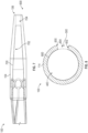
- FIG 4 illustrates a detailed side view of the scoring device 100 of Figure 1 , according to an embodiment of the present subject matter.
- the scoring device 100 includes the retention sleeve 114.
- the retention sleeve 114 facilitates retention of a catheter shaft (e.g., the catheter shaft 202, shown in Figure 2 ) by the scoring device 100.
- the retention sleeve 114 includes a catheter socket 400.
- the catheter socket 400 is configured to receive a catheter shaft, for instance the catheter shaft 202 (shown in Figure 2 ).
- the catheter socket 400 mechanically engages the catheter shaft, for example when the catheter shaft is received in the catheter socket 400.
- the catheter socket 400 grasps the catheter shaft to facilitate retention of the catheter shaft by the retention sleeve 114 (e.g., during loading, use of the assembly or the like).
- the scoring device 100 includes the scoring tool 108.
- the scoring tool 108 includes a balloon socket 402.
- the balloon socket 402 selectively receives a balloon, for instance the balloon 204 (shown in Figure 2 ).
- the scoring elements 110 surround the balloon socket 402, and with the balloon 204 loaded into the scoring device 100, the scoring elements 110 surround the balloon including continuously and discontinuously.
- the scoring elements 110 are directed away from the balloon socket 402.
- the scoring elements 110 include a scoring edge 404.
- the scoring edge 404 of the scoring elements 110 is directed away from the balloon socket 402, for instance to minimize engagement of the scoring edge 404 with the balloon 204.
- the balloon socket is located on a first side (e.g., an interior side, or the like) of the scoring element 110, and the scoring edge 404 is located on a second side (e.g., an exterior side, opposed side or the like) of the scoring element 110.
- the scoring edge 404 is located remotely relative to the balloon socket 402 to minimize interaction with the balloon 204.
- FIG. 5 illustrates a top view of the scoring device 100 of Figure 1 , according to an embodiment of the present subject matter.
- the scoring tool 108 includes the catheter socket 400 (shown in Figure 4 ).
- the catheter 200 includes a catheter port 500 that provides access to the catheter socket 400, for instance through the retention sleeve 114.
- the catheter port 500 is in communication with the catheter socket 400.
- the catheter port 500 is elastically deformable, for instance to facilitate ingress (or egress) of the catheter shaft into (our out of) the catheter socket 400.
- the catheter port 500 of the scoring device includes an elongate slot extending through the retention sleeve 114.
- the retention sleeve 114 is deformable and biases the port 500 (e.g., the slot) toward a closed configuration that captures a loaded catheter shaft within the catheter socket 400.
- a loading assembly biases the port 500 open, for instance with biasing of a catheter shaft, to initiate loading of the catheter shaft to the catheter socket 400 and continue loading through the port 500 (e.g., a slot) along the retention sleeve 114.
- Figure 6 illustrates a detailed top view of the scoring device 100 of Figure 1 , including the interface between the retention sleeve and the scoring tool 108.
- the scoring device 100 includes the catheter port 500, and the catheter port 500 is in communication with the catheter socket 400.
- the catheter port 500 facilitates selective reception of a catheter shaft by the retention sleeve 114.
- the catheter port 500 e.g., the retention sleeve 114 forming the port
- the catheter port 500 is elastically deformable to facilitate ingress (or egress) of the catheter shaft into (or out of) the catheter socket 400.
- the catheter port 500 includes a first face 600 and a second face 602 (also shown in Figure 8 ).
- the first face 600 is opposed to the second face 602.
- the first face 600 and the second face 602 extend between the proximal portion 102 and the distal portion 104.
- a slot 604 is optionally located between the opposed first and second faces 600, 602.
- the catheter port 500 is the slot 604 extending at least a portion of the length of the retention sleeve 114 (e.g., between the proximal and distal portions).
- Elastic deformation of the catheter port 500 varies a size of port 500, for instance by changing spacing between the first face 600 and the second face 602.
- the catheter port 500 is elastically deformable, the catheter port 500 is configured to receive a variety of catheter shafts having different profiles (e.g., diameters, cross sectional areas or the like). Accordingly, the catheter port 500 facilitates interchangeable reception of catheter shafts having varying profiles.
- elastic deformation of the catheter port 500 allows the catheter socket 400 to interchangeably receive a first catheter shaft having a first profile, a second catheter shaft having a different second profile or the like.
- catheter shafts are interchangeably received in the catheter socket 400 and loaded and unloaded through the catheter port 500 (and deformation of the port).
- Figure 7 illustrates a side view of the distal portion 104 of the scoring device 100 of Figure 1 , according to an embodiment of the present subject matter.
- the distal portion 104 includes the distal tip 106.
- the distal portion 104 of the scoring device 100 includes a distal tip socket 700.
- the distal tip socket 700 receives a portion of a catheter, for instance the catheter 200 (shown in Figure 2 ).
- the distal portion 214 of the catheter 200 (shown in Figure 2 ) is optionally seated in the distal tip socket 700 of the scoring device 100.
- the catheter 200 includes the distal coupling features 216 (shown in Figure 2 ).
- the distal tip socket 700 receives the distal coupling features 216.
- the distal tip socket 700 includes a tapered portion 702 that receives the distal coupling features 216 of the catheter 200.
- the tapered portion 702 that receives the distal coupling features 216 aligns the distal portion 214 of the catheter 200 relative to the distal tip socket 700.
- the distal coupling features 216 are seated in the tapered portion 702, for example with an interference fit, with complementary profiles or the like between the distal coupling features 216 and the tapered portion 702. Accordingly, the distal portion 214 of the catheter 200 is optionally seated in the distal tip socket 700.
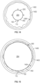
- Figure 8 illustrates a cross-sectional view of the scoring device 100 of Figure 6 at the line 8-8, according to an embodiment of the present subject matter.
- the retention sleeve 114 includes the first face 600 opposed to the second face 602.
- the retention sleeve 114 extends arcuately from the first face 600 to the second face 602.
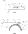
- the retention sleeve 114 has an arcuate cross section interrupted with the catheter port 500.
- the catheter port 500 is located between the first face 600 and the second face 602.
- the catheter port 500 includes the slot 604 (e.g., an elongate slot, or the like), and the slot 604 extends along the first face 600 and the second face 602.
- elastic deformation of the retention sleeve 114 varies the size of the port 500 (or slot 604), for instance by changing spacing between the first face 600 and the second face 602.
- the catheter port 500 is in communication with the catheter socket 400, and the catheter port 500 facilitates ingress (or egress) of a catheter shaft into (or out of) the catheter socket 400.
- the bias provided by the retention sleeve 114 facilitates retention of the catheter shaft within the catheter socket 400 during loading and use of the assembled device (e.g., catheter and scoring device).
- the retention sleeve 114 biases the catheter port 500 (or slot 604) toward the initial position shown in Figure 8 , and accordingly grasps and retains the catheter shaft therein.
- Figure 8 shows the catheter socket 400 has a first socket profile 800 (e.g., one or more of length, cross-section, shape, size, dimensions, contour, radius, perimeter, circumference, diameter, outline, boundary, configuration, pattern, arrangement, thickness or the like).
- the socket profile 800 varies with elastic deformation of the retention sleeve 114.
- the socket profile 800 is varied to change a volume of the catheter socket 400 and thereby accommodate various catheter shafts.
- Figure 9 illustrates an example of catheter assembly 900, according to an embodiment of the present subject matter.
- the catheter assembly 900 includes the scoring device 100 and the catheter 200.
- the scoring device 100 retains a catheter shaft, for instance the catheter shaft 202.
- the catheter socket 400 selectively receives the catheter shaft 202 through the catheter port 500.
- the retention sleeve 114 is elastically deformable to facilitate reception of the catheter shaft 202.
- Figure 9 shows the retention sleeve 114 in an initial configuration.
- the catheter socket 400 has the first socket profile 800.
- Elastic deformation of the catheter port 500 facilitates reception of the catheter shaft 202 by the catheter socket 400.
- the first face 600 is proximate the second face 602.
- elastic deformation separates the first face 600 from the second face 602, for instance to vary a characteristic 902 of the catheter port 500.
- Figure 9 shows the catheter shaft 202 of the catheter 200 having a first shaft profile 906.
- elastic deformation of the retention sleeve 114 allows the socket profile 800 to correspond with the shaft profile 906.
- the retention sleeve 114 mechanically engages the catheter shaft 202, for instance when the catheter shaft is selectively received by the catheter socket 400.
- the mechanical engagement of the catheter socket 400 with the catheter shaft 202 constrains relative movement between the catheter shaft 202 and the retention sleeve 114.
- the mechanical engagement constrains rotational movement of the catheter shaft 202 about a longitudinal axis of the retention sleeve 114.
- the mechanical engagement constrains lateral movement of the catheter shaft along the longitudinal axis of the retention sleeve 114.
- the retention sleeve 114 grasps the catheter shaft 202 to facilitate the catheter socket 400 mechanically engaging the catheter shaft 202.
- the retention sleeve 114 accordingly joins the scoring device 100 with the catheter 200 and consolidates the separate devices (scoring device 100 and catheter 200) in a unitary assembly for use by the physician.
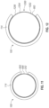
- Figure 10 illustrates another example of the catheter assembly 900 of Figure 9 , according to an embodiment of the present subject matter.
- the retention sleeve 114 is elastically deformable.
- the retention sleeve includes a loading configuration, and in loading configuration the retention sleeve is elastically deformed relative to the initial configuration (shown in Figure 9 ).
- the first face 600 and the second face 602 are biased apart (and the retention sleeve 114 is correspondingly deformed) relative to the initial configuration (shown in Figure 9 , where the first face 600 is proximate the second face 602).
- the profile of the catheter socket 400 is varied from the first socket profile 800 (shown in Figure 9 ) to a second socket profile 1000.
- a user engages (e.g., presses, pushes, squeezes, or the like and optionally using a loading device described herein) the catheter shaft 202 with the first and second faces 600, 602 to separate the first face 600 from the second face 602.
- the elastically deformed retention sleeve 114 having the catheter port 500 facilitates reception of the catheter shaft 202 through the catheter port 500.
- Figure 10 shows the retention sleeve 114 in a loading configuration, and the catheter shaft 202 is at least partially located within the catheter socket 400 (e.g., the catheter shaft at least partially intersects the catheter socket 400).
- elastic deformation of the retention sleeve 114 varies a profile of the catheter socket 400.
- Figure 10 shows the retention sleeve 114 in the loading configuration
- the catheter socket 400 has a second socket profile 1000.
- the second socket profile 1000 (shown in Figure 10 ) is larger than the first socket profile 800 (shown in Figure 9 ) because of the elastic deformation of the retention sleeve 114.
- Figure 11 illustrates yet another example of the catheter assembly 900 of Figure 9 , according to an embodiment of the present subject matter.
- Figure 11 shows the catheter shaft 202 selectively received (e.g., loaded) within the catheter socket 400 of the retention sleeve 114.
- the first socket profile 800 corresponds with the first shaft profile 906.
- the catheter socket 400 mechanically engages the catheter shaft 202, and the catheter shaft 202 is retained by the scoring device 100.
- Figure 12 illustrates still yet another example of the catheter assembly 900 of Figure 9 , according to an embodiment of the present subject matter.
- the catheter assembly 900 includes a second catheter 1 200 having a second catheter shaft 1202.
- the second catheter shaft 120 has a second shaft profile 1204 larger than the first shaft profile 906 (shown in Figure 11 ).
- a diameter of the second catheter shaft 1 202 is larger than a diameter of the first catheter shaft 202.
- the second catheter shaft 1202 is longer than the first catheter shaft 202.
- the catheter shaft 1202 is longer and has a larger diameter than the first catheter shaft 202.
- the socket profile 800 corresponds to the shaft profile 1204.
- the socket profile 800 corresponds with the shaft profile 1204 because the retention sleeve 114 is elastically deformable.
- the elastic deformation of the retention sleeve 114 enlarges the socket profile 800 and allows the catheter socket 400 (shown in Figure 8 ) to interchangeably receive catheters (or portions of catheters) having varied profiles.
- the scoring device 100 retains catheters with varying profiles, for example the first catheter 200 with the first shaft profile 906 (shown in Figure 11 ) or the second catheter 1200 with the second shaft profile 1204 (shown in Figure 12 ).
- FIG 13 illustrates a side view of the scoring tool 108 of the scoring device 1 00, according to an embodiment of the present subject matter.
- the scoring device 100 includes the scoring tool 108 extending between proximal and distal portions 102, 104 (shown in Figure 1 ).
- the scoring tool 108 includes the sections 112, such as the sections 112A, 112B, 112C.
- the scoring tool 108 includes one or more scoring elements 110, for example the first scoring element 110A and a second scoring element 110B.
- two or more of scoring elements 110 are included in a scoring array 1300.
- the scoring array 1300 includes scoring elements with varying scoring element profiles 1304.
- the first section 112A of the scoring tool 108 includes a first scoring section 1302A, as shown having a longitudinally extending configuration of scoring elements.
- the second section 112B of the scoring tool 108 includes a second scoring section 1302B, for instance a helical configuration of scoring elements.
- the second scoring section 1302B has a first scoring element profile 1304A (e.g., helical profile, elliptical profile, semicircular profile, or the like).
- the second scoring section 1302B includes the first scoring element 110A
- the first scoring element 110A has the first scoring element profile 1304A.
- the third section 112C of the scoring tool 108 includes a third scoring section 1302C.
- the third scoring section 1302C has a second scoring element profile 1304B (e.g., an elongate profile or the like).
- the third scoring section includes the second scoring element 110B, and the second scoring element 110B has the second scoring element profile 1304B similar or identical to the profile 1304B of the first scoring section 1302A.
- the first scoring element 110A is optionally coupled with the second scoring element 110B.
- the first scoring section 112A includes a third scoring element 110C, and the third scoring element 110C is coupled with the first scoring element 110A.
- a first end 1306 of the first scoring element 110A is coupled with the third scoring element 110C.
- a second end 1308 of the first scoring element 110A is coupled with the second scoring element 110B.
- the scoring section 1302B extends between the scoring sections 1302A and the scoring section 1302C.
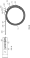
- Figure 14 illustrates the catheter 200 retained by the scoring device 100, according to an embodiment of the present subject matter.
- the balloon 204 of the catheter 200 is loaded within the balloon socket 402 (also shown in Figure 4 and 5 ), and the scoring device 100 retains the catheter 200 therein (e.g., with the retention sleeve 114).
- the scoring device 100 including the scoring elements 110 (and the catheter 200 including the balloon 204) are navigated through the vasculature 1400, for instance a vein, artery, or the like.
- matter such as plaque 1402 is adhered (e.g., bound, stuck, attached, compacted, or the like) to the vasculature 1400, for instance to a wall 1404 of the vasculature 1400.
- the balloon 204 and the scoring tool of the scoring device 100 are provided in a compressed or deflated configuration and the balloon 204 is inflated to an expanded or inflated configuration that also deploys the scoring tool 108.
- Figure 14 shows the balloon 204 in the deflated configuration (also shown in Figure 2 ).
- Figure 15 illustrates another example of the catheter 200 retained by the scoring device 100, according to an embodiment of the present subject matter.
- Figure 15 shows the balloon 204 in the inflated configuration (also shown in Figure 3 ) and shows the scoring tool 108 in an expanded configuration conforming to inflation of the balloon 204.
- the balloon 204 is enlarged to engage the scoring elements 110 with one or more of the vasculature 1400 or the plaque 1402 adhered to the vasculature 1400.
- the scoring tool 108 facilitates scoring of the plaque 1402.
- the balloon 204 and the scoring tool 108 work in concert to dilate the vessel.
- the scoring tool 108 separates or subdivides the plaque 1402 to facilitate dilation of the plaque 1402 with the inflated balloon 204.
- the scoring tool 108 enhances treatment of plaque 1402 from the vasculature 1400 including, but not limited to, dilation of vessels (compression of plaque 1402), removal of plaque or the like.
- Figure 16 illustrates an example of the catheter assembly 900 with the first catheter 200 and the scoring device 100, according to an embodiment of the present subject matter.
- Figure 16 shows the balloon 204 in the deflated configuration and with the first balloon profile 206.
- the balloon 204 of the catheter 200 is selectively received in the balloon socket 402 of the scoring device 100 and the scoring device 100 retains the catheter 200 therein (e.g., with the retention sleeve 114.).
- the scoring elements 110 are directed away from the balloon 202 selectively received in the balloon socket 402.
- the scoring tool includes an initial configuration and an expanded configuration.
- the scoring tool has a first tool profile 1600.
- the balloon 204 is selectively received in the balloon socket 402 with the balloon 204 in the deflated configuration.
- Figure 17 illustrates another example of the catheter assembly 900 with the first catheter 200 and the scoring device 100, according to an embodiment of the present subject matter.
- Figure 17 shows the balloon 204 in the inflated configuration and with the second balloon profile 300.
- the balloon 204 and the scoring tool 108 work in concert to dilate the vessel.
- the scoring tool 108 separates or subdivides matter (such as plaque) to facilitate dilation of the matter with the inflated balloon 204.
- the scoring tool 108 expands outward in conformity with the expansion of the balloon 204 to the inflated configuration.
- the scoring tool 108 accommodates the balloon 204 transitioning between the deflated and inflated configurations. For instance, the expansion of the balloon 204 radially displaces the scoring elements 110.
- the scoring tool 108 has a second tool profile 1700 with the balloon 204 in the inflated configuration (and having the second balloon profile 300).
- the second tool profile 1700 is larger than the first tool profile 1600.
- the scoring elements 110 are radially displaced to increase spacing between the scoring elements 110 (in comparison to the initial configuration) and provide the scoring tool 108 with the second tool profile 1700.
- the balloon socket 402 selectively receives the balloon 204 with varying balloon profiles (e.g., one or more of the balloon profiles 206, 300).
- FIG 18 illustrates an example of the catheter assembly 900 with the second catheter 1200 and the scoring device 100, according to an embodiment of the present subject matter.
- the second catheter 1200 includes a second balloon 1800 that includes deflated and inflated configurations.
- the balloon 1800 has a third balloon profile 1802 in the deflated configuration.
- the third balloon profile 1802 includes a first initial volume for the second balloon 1800.
- the first balloon profile 206 includes a second initial volume for the first balloon 1800,
- the first balloon profile 1802 is smaller than the third balloon profile 1802.
- the scoring tool 108 has a third tool profile 1804 with the balloon 1800 in the deflated configuration (and having the third balloon profile 1802).
- the third tool profile 1804 is optionally, larger than the first tool profile 1600.
- Figure 18 shows the balloon 204 in the deflated configuration and with the first balloon profile 206.
- the balloon 204 of the catheter 200 is selectively received in the balloon socket 402 of the scoring device 1 00.
- the balloon socket 402 selectively receives the balloons, for instance the balloon 204 or the balloon 1800 with varying balloon profiles (e.g., one or more of the balloon profiles 206, 300, 1802).
- Figure 19 illustrates another example of the catheter assembly 900 with the second catheter 1 200 and the scoring device 100, according to an embodiment of the present subject matter.
- Figure 19 shows the balloon 1800 in the inflated configuration with a fourth balloon profile 1900.
- the scoring tool 108 expands outward in conformity with the expansion of the balloon 1800 (or the balloon 204, shown in Figures 16-17 ) to the inflated configuration.
- the scoring tool 108 accommodates the balloon 1800 transitioning between the deflated and inflated configurations.
- the scoring tool 108 has a fourth tool profile 1902 with the balloon 1800 in the inflated configuration (and having the fourth balloon profile 1900).
- the fourth tool profile 1900 is larger than the third tool profile 1804.
- the scoring elements 110 are radially displaced to increase spacing between the scoring elements 110 (in comparison to the initial configuration) and provide the scoring tool 108 with the fourth tool profile 1902.
- the balloon socket 402 selectively receives the balloon 1 800 (or the balloon 204) with varying balloon profiles (e.g., one or more of the balloon profiles 206, 300, 1802, 1900).
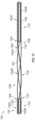
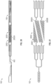
- Figures 20 and 21 illustrate side and detailed plan views (respectively) of another example of the scoring device 100, according to an embodiment of the present subject matter.
- the scoring device 100 includes at least one longitudinal expansion region 2000.
- the longitudinal expansion region 2000 includes one or more expansion ribbons 2002 that elastically deform and facilitate expansion of the scoring tool 108 (e.g., expansion from the initial configuration to the expanded configuration).
- the expansion ribbons 2002 in one example include a serpentine or concertina configuration that facilitates elastic expansion and contraction that maintains the scoring tool 108 in conformance with the balloon in both inflated and deflated configurations and intermediate configurations therebetween.
- the expansion ribbons 2002 permit inflation of a balloon received in the balloon socket of the scoring tool 108 while minimizing interference of inflation that may affect the specified inflation configuration of the balloon (e.g., by binding, anchoring or the like with struts or features that fail to expand).
- the expansion ribbons 2002 facilitate one or more of axial or radial expansion of the scoring tool 108.
- the expansion of the scoring tool 1 08 from the initial configuration to the expanded configuration in some examples axially expands and radially expands the scoring tool.
- the radius of the balloon perimeter relative to the catheter shaft enlarges through inflation of the balloon.
- the scoring tool 108 shown in Figures 20 and 21 expands to accommodate the enlargement. Because the radius of the balloon increases during expansion and the scoring tool 108 is coupled along the balloon, the scoring tool follows the increase in radius (at both ends of the balloon) and thereby lengthens with the expansion ribbons 2002 to accommodate the change in balloon radius while minimizing interference with balloon inflation.
- the expansion ribbons 2002 are isolated from proximate expansion ribbons 2002.
- the scoring tool 108 includes a first ribbon 2002A isolated from a second ribbon 2002B.
- the first and second ribbons 2002A, B separately extend between scoring elements or other components of the scoring tool 108.
- the first ribbon 2002A is not directly coupled with the second ribbon 2002B. Accordingly, the first ribbon 2002A is allowed to expand axially independently of the axial expansion of the ribbon 2002B.
- axial expansion of the scoring tool 108 is enhanced, for instance because the first ribbon 2002A does not bind with the second ribbon 2002B while the scoring tool transitions between initial and expanded configurations.
- each of the ribbons 2002 independently conforms to changes in the balloon during inflation without interference from proximate ribbons 2002.
- the ribbons 2002 extend helically around the balloon socket 402. Helically winding the ribbons 2002 around the balloon socket 402 minimizes sagging or separation of the scoring tool 108 from a balloon (e.g., the balloon 1800, shown in Figure 18 ) selectively received within the balloon socket 402. Accordingly, retention and engagement of the scoring tool 108 to the loaded balloon is enhanced with helical wrapping of the balloon socket (and the balloon therein) with the ribbons 2002.
- a balloon e.g., the balloon 1800, shown in Figure 18
- scoring device 100 performance of the scoring device 100 is enhanced, because the scoring tool 108 mechanically engages the balloon in each of the deflated and inflated configurations (and intermediate configurations) and helical winding of the ribbons 2002 around the balloon socket 402 enhances the mechanical engagement between the scoring tool 108 and the balloon and thereby facilitates enhanced conformance of the scoring tool 108 to the profile of the balloon.
- FIG 22 illustrates an example of a loading assembly 2200, according to an embodiment of the present subject matter.
- the loading assembly 2200 includes an assembly tool 2202 that facilitates assembly of a catheter assembly, for example the catheter assembly 900 (shown in Figure 9 ), having the scoring device 100 described herein and one or more catheters (e.g., balloon catheters).
- the assembly tool 2202 facilitates assembly of the scoring device 100 to a catheter, for instance the catheter 200 (shown in Figure 2 ) or the catheter 1200 (shown in Figure 12 ).
- the assembly tool 2202 facilitates elastic deformation of the catheter port 500 (shown in Figure 5 ) and ingress of the catheter 200 into the catheter socket 400 of the scoring device 100.
- the assembly tool 2202 facilitates reception of a balloon within the balloon socket of the scoring device 100, opening of the scoring device 100, and loading of the catheter shaft into the retention sleeve for retention of the shaft therein.
- the assembly tool 2202 facilitates assembly of the scoring device 100 with a plurality of catheters, each of the catheters having different profiles.
- the assembly tool 2202 includes an assembly interface 2204.
- the assembly interface 2204 receives each of the retention sleeve 114 and the catheter 200 in separated or partially separated conditions. For instance, the assembly interface 2204 facilitates assembly of the retention sleeve 114 over the catheter shaft 202.
- the loading assembly 2200 includes a scoring tool sheath 2206 coupled with the assembly tool 2202.
- the scoring tool sheath 2206 surrounds and protects the scoring tool 108 of the scoring device 1 00.
- the scoring tool sheath 2206 extends between the assembly interface 2204 and a distal portion of the loading assembly 220.
- the loading assembly 2200 includes a catheter loading mandrel 2210.
- the catheter loading mandrel 2210 facilitates alignment of components of the loading assembly 2200.
- the mandrel 2210 facilitates axial alignment of the scoring device 100 with the catheter 200.
- the catheter loading mandrel 2210 is optionally coupled with the scoring tool sheath 2206.
- the catheter loading mandrel 2210 extends through the assembly tool 2202 (and the assembly interface 2204) from an opposed end of the scoring tool sheath 2206.
- the catheter loading mandrel 2210 extends through one or more of the catheter socket 400 of the retention sleeve 114 or the balloon socket 402 of the scoring tool 108.
- the catheter loading mandrel 2210 extends between the proximal and distal portions 102, 104 of the scoring device 100 and is within the catheter and balloon sockets 400, 402 of the scoring device.
- the distal tip socket 700 of the scoring device passes the catheter loading mandrel 2210 through the balloon socket 402.
- the mandrel 2210 optionally extends through the distal tip socket 700, for example through the mandrel lumen 704 of the distal portion 104 of the scoring device 100. Accordingly, the mandrel 2210 extends through one or more components of the loading assembly 2200 to facilitate alignment (and assembly) of the scoring device 100 and the catheter 200.
- Figure 23 illustrates a cross-sectional view the loading assembly 2200 including the assembly interface 2204, according to an embodiment of the present subject matter.
- the assembly interface 2204 includes a loading interface 2300 and an assembly fitting 2302.
- the loading interface 2300 facilitates assembly of the catheter assembly 900, for example by aligning the retention sleeve 114 with the mandrel 2210.
- the mandrel 2210 is at least partially received in the catheter socket 400.
- the mandrel 2210 elastically deforms the catheter port 500 and the retention sleeve to facilitate ingress of the catheter shaft 202 into the catheter socket 400.
- the mandrel 2210 facilitates assembly of the catheter assembly 900 by assisting in the elastic deformation of the retention sleeve. Accordingly, the mandrel 2210 facilitates the catheter socket 400 selectively receiving the catheter shaft 202 by elastically deforming the retention sleeve 114 and aligning the catheter 200 relative to the scoring device 100. In another example, the catheter loading mandrel 2210 guides the balloon (e.g., the balloon 204) of the catheter through the assembly tool 2202 and into the balloon socket 402 of the scoring tool 108.
- the balloon e.g., the balloon 204
- the assembly interface 2204 includes the assembly fitting 2302.
- the assembly fitting 2302 facilitates assembly of the retention sleeve 114 over the catheter 200.
- the assembly fitting 2302 receives each of the retention sleeve 114 and the catheter 200, with the sleeve 114 and the catheter 200 in a decoupled configuration.
- the decoupled configuration includes the catheter shaft 202 separate from the catheter socket 400 of the scoring device 100.
- the balloon of the catheter is received within the balloon socket 402 of the scoring tool 108.
- the mandrel 2210 guides the balloon (e.g., the balloon 204) of the catheter through the assembly tool 2202 and into the balloon socket 402 of the scoring tool 108.
- the mandrel 2210 and the loading interface 2300 cooperate to align the retention sleeve 114 relative to the catheter shaft 202.
- the assembly fitting 2302 receives each of the retention sleeve 114 and the catheter 200 (for instance the catheter shaft 202) and assembles the retention sleeve over the catheter 200 to provide an assembled configuration to the catheter assembly 900.
- the assembly fitting 2302 is a collet 2304 that extends around the retention sleeve 114 and the catheter 200.
- the assembly collet 2304 is compressible (e.g., elastomeric, squeezable, shrinkable, squishable, or the like) to assemble the retention sleeve 114 over the balloon catheter 200.
- the assembly fitting 2302 biases the retention sleeve 114 over the catheter 200.
- the assembly fitting 2302 opens an elongate slot (e.g., the slot 604, shown in Figure 6 ) through radial compression around each of the retention sleeve and the catheter 200.
- the compression biases the catheter 200 through the catheter port 500 of the retention sleeve (e.g., an elongate slot extending along the retention sleeve).
- opening the elongate slot facilitates reception of the catheter 200 within the retention sleeve 114 because elastic deformation of the retention sleeve 114 allows ingress (or egress) of the catheter shaft 202 into the catheter socket 400.
- the assembly fitting 2302 facilitates loading of the catheter 200 to the scoring device 100 by driving the catheter 200 through the catheter port 500 and into the catheter socket of the retention sleeve 114.
- the assembly fitting 2302 is forced (e.g., pushed, extruded, compressed, pulled, drawn, or the like) through the loading interface 2300, for instance to compress the assembly fitting 2302 (and assemble the scoring device 100 with the catheter 200).
- the assembly interface 2204 is rotatably coupled relative to the assembly collet 2304.
- the assembly interface 2204 is rotatably coupled with the loading interface 2300.
- the assembly fitting 2302 is received in the loading interface 2300, and rotation of the assembly interface 2204 compresses the assembly fitting 2302 with the loading interface 2300.
- the assembly collet 2304 is forced through a compression orifice 2306 of the loading interface 2300.
- the compression orifice 2306 includes a constriction (e.g., reduction in cross-sectional area, or the like) within the loading interface 2300, and forcing of the collet 2304 through the orifice 2306 compresses the assembly collet 2304.
- the collet 2304 is deformable, and compression of the collet 2304 deforms the collet 2304 to engage the collet 2304 with components received therein (e.g., one or more of the retention sleeve 114, the catheter, or the mandrel 2210, or the like).
- the loading assembly evenly applies a force across the catheter assembly as the collet 2304 is forced through the orifice 2306 (e.g., the collet 2304 is compressed concentrically around a perimeter of the collet 2304).
- assembly fitting 2302 clamps the retention sleeve 114 to the catheter 200, for instance by compressing the collet 2304 with one or more components of the catheter 200 located in the collet 2304. Accordingly, the clamping of the retention sleeve to the catheter 200 minimizes separation of the retention sleeve 114 from the catheter 200.
- rotation of the assembly interface 2204 compresses the assembly fitting 2302.
- the loading assembly 2200 includes an assembly drive 2308
- rotation of the assembly interface 2204 displaces the assembly drive 2308 relative to the loading interface 2300.
- the assembly interface 2204 (and the assembly drive 2308) are rotatably coupled with the assembly fitting 2302, and in an example, the displacement of the assembly drive 2308 compresses the assembly collet 2304 by engaging with the collet 2304 to force the collet 2304 through the compression orifice 2306 of the loading interface 2300.
- a barrel of the assembly drive 2308 engages with the assembly fitting 2204 (in this example the collet 2304).
- the barrel of the assembly drive 2308 is received by a corresponding barrel socket of the loading interface 2300. Accordingly, the assembly fitting 2302 transitions the retention sleeve 114 and the catheter from the decoupled configuration to the assembled configuration.
- the loading assembly 2200 facilitates biasing of the retention sleeve 114 over the catheter to assemble the catheter assembly 900 (shown in Figure 11 ).
- the loading assembly 2200 includes a cutter 2310.
- the cutter 2310 includes a sleeve cutting element 2312 received in a sleeve cutting housing 2314.
- the sleeve cutting housing 2314 is coupled with the assembly tool 2202, for instance coupled with the loading interface 2300.
- the sleeve cutting element 2312 is positioned along the retention sleeve 114, and the retention sleeve 114 passes through the sleeve cutting element 2312.
- the catheter assembly 900 includes a decoupled configuration and an assembled configuration.
- the retention sleeve 114 passes through a cutting orifice (e.g., the cutting orifice 3200, shown in Figure 32 ) of the sleeve cutting element 2312.
- a user engages with the cutter 2310, for instance to rotate the sleeve cutting element 2312 relative to the sleeve cutting housing 2314.
- rotation of the sleeve cutting element 2312 severs the retention sleeve 114.
- the sleeve cutting element 2312 proximate the cutting orifice engages with the retention sleeve 114 to sever (e.g., cut, slice, chop, shear, or the like) the retention sleeve 114.
- the sleeve cutting element severs the retention sleeve 114, for instance to trim the retention sleeve 114 to a specified length (e.g., to a retention sleeve length corresponding to a length of a catheter shaft). Accordingly, the retention sleeve 114 is severed proximate the catheter, for example to facilitate marriage of the retention sleeve 114 with the catheter.
- Figure 24 illustrates a detailed side view of the distal portion 2208 of the loading assembly 2200, according to an embodiment of the present subject matter.
- the mandrel 2210 extends through the balloon socket 402 of the scoring device 100, and the scoring elements 110 surround the balloon socket 402.
- the scoring device 100 includes the distal portion 104, and the mandrel 2210 extends through the distal portion 104 of the scoring device 100 (e.g., through a distal tip socket, or the like).
- Figure 25 illustrates the loading assembly 2200 including the catheter 200, according to an embodiment of the present subject matter.
- the catheter 200 is loaded onto the mandrel 2210, and the mandrel 2210 facilitates assembly of the catheter with the scoring device 100.
- the mandrel 2210 guides the balloon 204 (shown in Figure 26 ) of the catheter 200 through one or more of the catheter socket 400 or the balloon socket 402.
- the balloon optionally extends through the balloon socket 402 and the distal portion 214 of the catheter 200 is seated into the distal portion 104 of the scoring device 100 (e.g., the balloon 202 is engaged with the tapered portion 702 of the distal tip socket 700, shown in Figure 7 ).
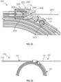
- Figure 26 illustrates the distal portion 2208 of the loading assembly 2200, according to an embodiment of the present subject matter.
- the balloon 204 is optionally located in the balloon socket 402, and into the distal tip socket 700 of the scoring device 100.
- Figure 27 illustrates a side view of an example of the loading assembly 2200 with the scoring tool sheath 2206 and the assembly interface 2204 separated from the assembly tool 2202, according to an embodiment of the present subject matter.
- rotation of the assembly interface 2204 facilitates separation of one or more of the assembly interface 2204, the sheath 2206, or the mandrel 2210 from the assembly tool 2202.
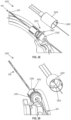
- the catheter 200 optionally includes a hub 2700, and in some examples the hub is engaged with the loading interface 2300 (e.g., by pulling the catheter 200 through the assembly tool 2202).
- the catheter such as the catheter shaft 202 and the hub 2700 are moved through the assembly tool 2202.
- the catheter 200 is loaded into the scoring device 100.
- the distal portions 104, 214 of the catheter 200 and the scoring device are moved (e.g., pushed, pulled, or the like) relative to the assembly tool 2202 and the retention sleeve 114 is biased over the catheter shaft 202 of catheter 200. Movement of the catheter assembly 900 relative to the assembly tool 2202 optionally engages the hub 2700 with the loading interface 2300 (shown in Figure 30 ).
- Figure 28 illustrates a detailed perspective view of the loading assembly 2200, according to an embodiment of the present subject matter.
- the assembly interface 2204 includes a locking feature 2800 that engages with the loading interface 2300 to attach the assembly interface 2204 with the assembly tool 2202.
- the assembly interface 2300 includes a socket 2802 that receives the locking feature 2800 to attach the assembly interface 2204 with the assembly tool 2202.
- rotation of the assembly interface 2204 disengages the locking feature 2800 from the socket 2802, for instance to facilitate separation of one or more of the assembly interface 2204, the sheath 2206, or the mandrel 2210 from the assembly tool 2202.
- Figure 28 shows the catheter shaft 202 on a first (e.g., distal, or the like) side of the assembly tool 2202. Additionally, the balloon 204 is received in the balloon socket 402 on a second side of the scoring tool 108.
- Figure 29 illustrates another detailed perspective view of the loading assembly 2200, according to an embodiment of the present subject matter.
- the assembly interface 2204 includes drive coupling features 2900
- the assembly drive 2308 includes corresponding interface coupling features 2902.
- the drive coupling features 2900 engage with the interface coupling features 2902, for example to facilitate displacement of the assembly drive 2308.
- rotation of the assembly interface 2204 correspondingly rotates the assembly drive 2308 because the drive coupling features 2900 are engaged with the interface coupling features 2902.
- the assembly drive 2308 is threadingly engaged with the loading interface 2300, and rotation of the assembly drive 2308 displaces the assembly drive 2308 relative to the loading interface 2300.
- the loading assembly 2200 facilitates assembly of the catheter assembly 900, for instance by transitioning the retention sleeve 114 (shown in Figure 27 ) and the catheter 200 from the decoupled configuration to tire assembled configuration.
- the retention sleeve and catheter in the assembled configuration extend from the assembly fitting 2302.
- Figure 30 illustrates another side view of the loading assembly 2200 including the catheter 200, according to an embodiment of the present subject matter.
- the catheter 200 and the scoring device 100 are displaced relative to the assembly tool 2202 (e.g., by pulling the distal portion 104, or the like).
- the hub 2700 is engaged with the loading interface 2300 by displacing the scoring device 100 and the catheter 200 relative to the assembly tool 2202.
- displacing the scoring device 100 and the catheter 200 facilitates assembly of the retention sleeve 114 over the catheter 200, for instance by biasing the retention sleeve 114 over the catheter shaft 202.
- the loading assembly 2200 facilitates the selective reception of the balloon 204 within the balloon socket 200 (also shown in Figure 14 ) and the selective reception of the catheter shaft 202 within the catheter socket 400 (also shown in Figure 11 ).
- Figure 31 illustrates a side view of the loading assembly 2200 including the cutter 2310, according to an embodiment of the present subject matter.
- the cutter 2310 includes a cutting operator 3100 (e.g., a handle, lever, switch, or the like) that operates the cutter 2310 to sever the retention sleeve 114.
- the cutting operator 3100 is coupled with the sleeve cutting element 2312 (also shown in Figure 32 ), and the cutting operator is rotated to correspondingly rotate the cutting element 2312. As described herein, rotation of the cutting element 2312 severs the retention sleeve 114.
- the cutter 2310 facilitates trimming of the retention sleeve 114, for instance to terminate the retention sleeve 114 proximate to the hub 2700.
- the cutter 2310 allows the scoring device 100 to retain a plurality of catheters (with each of the catheters having a different profile, such as the catheters 200, 1200 shown respectively in Figures 2 and 12 ), for instance because the cutter 2310 allows the length of the retention sleeve 114 to be trimmed to correspond with a length of one or more of the plurality of catheters.
- the loading assembly 2200 facilitates transitioning of the catheter assembly 900 between the decoupled and assembled configurations, with the catheter assembly 900 including a plurality of catheters (with each of the catheters having a different profile).
- FIG 32 illustrates a cross-sectional view of the loading assembly 2200, according to an embodiment of the present subject matter.
- the loading assembly 2200 includes the cutter 2310, and the cutter 2.310 includes the sleeve cutting element 2312.
- the sleeve cutting element 2312 includes a cutting orifice 3200.
- the catheter assembly 900 includes a decoupled configuration and an assembled configuration. In the decoupled configuration, the retention sleeve 114 passes through the cutting orifice 3200 of the sleeve cutting element 2312.
- a user engages with the cutter 2310, for instance by engaging with the cutting operator 3100 (shown in Figure 31 ) to rotate the sleeve cutting element 2312 relative to the sleeve cutting housing 2314.
- rotation of the sleeve cutting element 2312 severs the retention sleeve 114.
- the sleeve cutting element 2312 proximate the cutting orifice 3200 engages with the retention sleeve 114 to sever (e.g., cut, slice, chop, shear, or the like) the retention sleeve 114.
- the sleeve cutting element 2312 severs the retention sleeve 114, for instance to trim the retention sleeve 114 to a specified length (e.g., to a retention sleeve length corresponding to a length of a catheter shaft). Accordingly, the retention sleeve 114 is severed proximate the catheter, for example to facilitate marriage of the retention sleeve 114 with the catheter shaft 202.
- the hub 2700 of the catheter 200 is at least partially received by the loading interface 2300.
- the loading interface 2300 receives a portion of the hub to align the proximal portion of the catheter 200 relative to the proximal portion 102 of the scoring device 100.
- the catheter assembly 900 includes one or more components of the loading assembly 2200, for instance the loading interface 2300.
- Figure 33 illustrates yet another side view of the loading assembly 2200, according to an embodiment of the present subject matter.
- one or more components of the loading assembly 2200 are separable from other ones of the components of the loading assembly 2200.
- the loading interface 2300 is separable from the cutter 2310. Accordingly, the cutter 2310 (or other components of the loading assembly 2200) are optionally discarded once the catheter assembly 900 is transitioned to the assembled configuration.
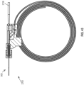
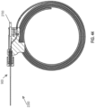
- Figures 34-44 illustrate various views of another example of the loading assembly 2200.
- the loading assembly 2200 includes one or more of the assembly tool 2202, assembly interface 2204, and the loading interface 2300, or the assembly fitting 2302.
- the loading assembly 2200 optionally includes the assembly drive 2308.
- the assembly interface 2204 receives each of the retention sleeve 114 and the catheter 200 in separated or partially separated conditions.
- the assembly interface 2204 facilitates assembly of the retention sleeve 114 over the catheter shaft 202.
- the assembly interface 2204 is rotatably coupled relative to the assembly fitting 2300. In one example, the assembly interface 2204 is rotatably coupled with the loading interface 2300.
- the assembly fitting 2302 is received in the loading interface 2300, and rotation of the assembly interface 2204 compresses the assembly fitting 2302 with the loading interface 2300.
- the assembly fitting 2302 is forced through the compression orifice 2306 of the loading interface 2300.
- the compression orifice 2306 includes a constriction (e.g., reduction in cross-sectional area, or the like) within the loading interface 2300, and forcing of the assembly fitting through the orifice 2306 compresses the assembly fitting 2302.
- the loading interface 2300 facilitates transitioning of the catheter assembly 900 from the decoupled configuration to the assembled configuration. For instance, the loading interface 2300 biases the retention sleeve 114 over the catheter shaft 202.
- the assembly fitting 2302 guides the retention sleeve 114 onto catheter shaft 202 and loads the shaft 202 into the sleeve 114 similar to as discussed herein.
- the assembly interface 2204 is rotated relative to the drive 2308 and the interior (e.g., a barrel, or the like) of the assembly interface 2204 is driven toward an affixation seal, such as the collet 2304.
- the assembly fitting 2302 is the assembly interface 2204.
- longitudinal compression of the assembly interface 2302 causes inward compression of the assembly interface 2302, and corresponding compression of the retention sleeve 114 and the catheter 200.
- Two or more of these fitting assembly examples can work together to ensure the seating of the catheter shaft 202 in the retention sleeve 114. Accordingly, the loading assembly 2200 facilitates transitioning of the catheter assembly 900 from the decoupled configuration to the assembled configuration.
- Figure 45 illustrates a diagram of a method 4500 for assembling a scoring device to a catheter, including one or more of the scoring device 100 or the catheters 200, 1200 described herein.
- the method 4500 reference is made to one or more components, features, functions and operations previously described herein. Where convenient, reference is made to the components, features, operations and the like with reference numerals.
- the reference numerals provided are exemplary and are not exclusive. For instance, components, features, functions, operations and the like described in the method 4500 include, but are not limited to, the corresponding numbered elements provided herein and other corresponding elements described herein (both numbered and unnumbered) as well as their equivalents.
- the method 4500 includes delivering a catheter shaft 202 of the catheter 200 into a catheter socket 400 of a scoring device 100.
- the method 4500 includes delivering a balloon 204 of the catheter shaft 202 into a balloon socket 402 of the scoring device 100.
- the method 4500 includes mechanically locking the catheter shaft 202 with a retention sleeve 114 of the scoring device 100.
- a force is optionally applied to the catheter shaft 202 to deliver the catheter shaft 202 into the balloon socket 402.
- delivering the catheter shaft 202 into the catheter socket 400 includes delivering the catheter shaft 202 through a catheter port 500.
- the catheter port 500 is in communication with the catheter socket 400 to facilitate reception of the catheter 200 by the scoring device 100.
- the method 4500 optionally includes expanding the scoring array 100 with the balloon 204 of the catheter 200 (e.g., between deflated and inflated configurations).
- mechanically locking the catheter shaft 202 with the retention sleeve 114 includes biasing the retention sleeve 114 over the catheter shaft 202.
- biasing the retention sleeve 114 over the catheter shaft 202 includes delivering each of the retention sleeve 114 and the catheter shaft 202 into an assembly fitting, for instance the assembly fitting 2304 of the loading assembly 2200.
- the assembly fitting 2304 optionally biases the catheter shaft into the catheter socket through a catheter port.
- Geometric terms such as “parallel”, “perpendicular”, “round”, or “square”, are not intended to require absolute mathematical precision, unless the context indicates otherwise. Instead, such geometric terms allow for variations due to manufacturing or equivalent functions. For example, if an element is described as “round” or “generally round,” a component that is not precisely circular (e.g., one that is slightly oblong or is a many-sided polygon) is still encompassed by this description.
- Method examples described herein can be machine or computer-implemented at least in part. Some examples can include a computer-readable medium or machine-readable medium encoded with instructions operable to configure an electronic device to perform methods as described in the above examples.
- An implementation of such methods can include code, such as microcode, assembly language code, a higher-level language code, or the like. Such code can include computer readable instructions for performing various methods. The code may form portions of computer program products. Further, in an example, the code can be tangibly stored on one or more volatile, non-transitory, or non-volatile tangible computer-readable media, such as during execution or at other times.
- Examples of these tangible computer-readable media can include, but are not limited to, hard disks, removable magnetic disks, removable optical disks (e.g., compact disks and digital video disks), magnetic cassettes, memory cards or sticks, random access memories (RAMs), read only memories (ROMs), and the like.
Landscapes
- Health & Medical Sciences (AREA)
- Life Sciences & Earth Sciences (AREA)
- Heart & Thoracic Surgery (AREA)
- Animal Behavior & Ethology (AREA)
- Veterinary Medicine (AREA)
- Engineering & Computer Science (AREA)
- Public Health (AREA)
- Biomedical Technology (AREA)
- General Health & Medical Sciences (AREA)
- Surgery (AREA)
- Pulmonology (AREA)
- Hematology (AREA)
- Anesthesiology (AREA)
- Biophysics (AREA)
- Child & Adolescent Psychology (AREA)
- Vascular Medicine (AREA)
- Nuclear Medicine, Radiotherapy & Molecular Imaging (AREA)
- Medical Informatics (AREA)
- Molecular Biology (AREA)
- Media Introduction/Drainage Providing Device (AREA)
Claims (15)
- Eine Ritzvorrichtung (100), die zum Halten eines Katheterschafts (202) konfiguriert ist, wobei die Ritzvorrichtung Folgendes beinhaltet:einen proximalen Abschnitt (102);einen distalen Abschnitt (104), der eine distale Spitze (106) umfasst;eine Haltehülse (114), die sich zwischen dem proximalen und dem distalen Abschnitt erstreckt, wobei die Haltehülse eine Katheteraufnahme (400) aufweist, die dazu konfiguriert ist, den Katheterschaft (202) selektiv aufzunehmen und mechanisch in Eingriff zu nehmen, und die Haltehülse dazu konfiguriert ist, sich von einem distalen Schaftabschnitt (214) in die unmittelbare Nähe zu einer Nabe (2700) des Katheterschafts (202) zu erstrecken; undein Ritzwerkzeug (108), das mit der Haltehülse (114) in unmittelbarer Nähe zu dem distalen Abschnitt (104) gekoppelt ist und sich in Bezug auf die Haltehülse (114) distal befindet, wobei das Ritzwerkzeug Folgendes umfasst:eine Ballonaufnahme (402), die dazu konfiguriert ist, einen Ballon (204) des Katheterschafts (202) selektiv aufzunehmen; undein oder mehrere Ritzelemente (110), die sich um die Ballonaufnahme (402) erstrecken, wobei das eine oder die mehreren Ritzelemente dazu konfiguriert sind, örtlich begrenztes Ritzen einer Vaskulatur bereitzustellen.
- Ritzvorrichtung gemäß Anspruch 1, ferner beinhaltend einen verformbaren Katheterzugang (500), der in der Haltehülse (114) umfasst ist, wobei:der Katheterzugang mit der Katheteraufnahme (400) in Verbindung steht; undder Katheterzugang elastisch verformbar ist und dazu konfiguriert ist, den Katheterschaft (202) aufzunehmen.
- Ritzvorrichtung gemäß Anspruch 2, wobei:die Haltehülse (114) eine erste und eine zweite Fläche (600, 602) umfasst, die einander gegenüberliegen und sich zwischen dem proximalen und dem distalen Abschnitt erstrecken; undder verformbare Katheterzugang (500) einen Schlitz umfasst, der sich entlang der ersten und der zweiten Fläche, die einander gegenüberliegen, erstreckt.
- Ritzvorrichtung gemäß Anspruch 2, wobei:die Haltehülse (114) dazu konfiguriert ist, sich elastisch zu verformen, und die elastische Verformung der Haltehülse ein Aufnahmeprofil der Katheteraufnahme (400) verändert; undelastische Verformung der Haltehülse eine Eigenschaft des Katheterzugangs (500) verändert, um das Hindurchgelangen des Katheterschafts (202) durch den Katheterzugang zu erleichtern.
- Ritzvorrichtung gemäß Anspruch 2, wobei:sich die Haltehülse (114) bogenförmig von einer ersten Fläche zu einer zweiten Fläche erstreckt;sich der Katheterzugang (500) zwischen der ersten Fläche (600) und der zweiten Fläche (602) befindet; unddie Haltehülse (114) eine Ausgangskonfiguration und eine Belastungskonfiguration umfasst, wobei:sich in der Ausgangskonfiguration die erste Fläche (600) in unmittelbarer Nähe zu der zweiten Fläche (602) befindet; undin der Belastungskonfiguration die erste Fläche (600) und die zweite Fläche (602) zum Aufnehmen des Katheterschafts (202) relativ zu der Ausgangskonfiguration voneinander beabstandet verformt sind.
- Ritzvorrichtung gemäß Anspruch 2, die eines oder mehrere der Folgenden beinhaltet:wobei sich der verformbare Katheterzugang (500) entsprechend der Haltehülsenlänge von dem proximalen zu dem distalen Abschnitt entlang der Haltehülse (114) erstreckt; undwobei der distale Abschnitt (104) eine distale Spitzenaufnahme (700) umfasst, die zum Fixieren eines distalen Katheterschaftabschnitts (214) konfiguriert ist.
- Ritzvorrichtung gemäß Anspruch 6, wobei die distale Spitzenaufnahme (700) ein Mandrinlumen (704) umfasst, das dazu konfiguriert ist, einen Mandrin (2210) durch die distale Spitzenaufnahme hindurchzulassen.
- Ritzvorrichtung gemäß Anspruch 6, wobei die distale Spitzenaufnahme (700) Folgendes umfasst:einen verjüngten Abschnitt (702), der dazu konfiguriert ist, distale Kopplungsmerkmale (216) des distalen Katheterschaftabschnitts (214) aufzunehmen; undwobei das Aufnehmen der distalen Kopplungsmerkmale (216) den distalen Katheterschaftabschnitt (214) relativ zu der distalen Spitzenaufnahme (700) ausrichtet und den distalen Katheterschaftabschnitt (214) innerhalb der distalen Spitzenaufnahme (700) fixiert.
- Ritzvorrichtung gemäß Anspruch 1, ferner beinhaltend den in der Katheteraufnahme (400) aufgenommenen Katheterschaft (202).
- Ritzvorrichtung gemäß Anspruch 6, wobei sich der Ballon (204) des Katheterschafts (202) durch die Ballonaufnahme (402) des Ritzwerkzeugs (108) erstreckt und der distale Katheterschaftabschnitt (214) mit der distalen Spitzenaufnahme (700) fixiert ist.
- Ritzvorrichtung gemäß Anspruch 9, wobei der mechanische Eingriff der Katheteraufnahme (400) mit dem Katheterschaft (202) eine Relativbewegung zwischen dem Katheterschaft (202) und der Haltehülse (114) einschränkt.
- Ritzvorrichtung gemäß Anspruch 11, wobei eine Relativbewegung eine laterale Bewegung des Katheterschafts (202) entlang einer Längsachse der Haltehülse (114) umfasst; oder
wobei eine Relativbewegung eine Drehbewegung des Katheterschafts (202) um eine Längsachse der Haltehülse (114) umfasst. - Ritzvorrichtung gemäß Anspruch 11, wobei der mechanische Eingriff der Katheteraufnahme (400) das Greifen des Katheterschafts (202) durch die Haltehülse (114) umfasst.
- Ritzvorrichtung gemäß Anspruch 1, wobei das Ritzwerkzeug (108) eine Ausgangskonfiguration und eine ausgedehnte Konfiguration umfasst, wobei:in der Ausgangskonfiguration das Ritzwerkzeug (108) ein erstes Werkzeugprofil aufweist; undin der ausgedehnten Konfiguration das Ritzwerkzeug (108) ein zweites Werkzeugprofil aufweist, wobei das zweite Werkzeugprofil größer als das erste Werkzeugprofil ist.
- Ritzvorrichtung gemäß Anspruch 14, ferner beinhaltend den in der Ballonaufnahme (402) befindlichen Ballon (204), wobei:der Ballon (204) dazu konfiguriert ist, sich zwischen einer entleerten Konfiguration undeiner aufgeblasenen Konfiguration auszudehnen, und wobei:in der entleerten Konfiguration der Ballon (204) ein erstes Ballonprofil aufweist und das Ritzwerkzeug (108) das erste Werkzeugprofil aufweist; undin der aufgeblasenen Konfiguration:der Ballon (204) ein zweites Ballonprofil aufweist, das größer als das erste Ballonprofil ist; unddas Ritzwerkzeug (108) das zweite Werkzeugprofil aufweist.
Applications Claiming Priority (3)
| Application Number | Priority Date | Filing Date | Title |
|---|---|---|---|
| US201962951971P | 2019-12-20 | 2019-12-20 | |
| US201962951020P | 2019-12-20 | 2019-12-20 | |
| PCT/US2020/066281 WO2021127609A1 (en) | 2019-12-20 | 2020-12-20 | Universal scoring device |
Publications (4)
| Publication Number | Publication Date |
|---|---|
| EP4076230A1 EP4076230A1 (de) | 2022-10-26 |
| EP4076230A4 EP4076230A4 (de) | 2023-04-12 |
| EP4076230C0 EP4076230C0 (de) | 2024-10-16 |
| EP4076230B1 true EP4076230B1 (de) | 2024-10-16 |
Family
ID=76478032
Family Applications (1)
| Application Number | Title | Priority Date | Filing Date |
|---|---|---|---|
| EP20903837.1A Active EP4076230B1 (de) | 2019-12-20 | 2020-12-20 | Universelle ritzvorrichtung |
Country Status (3)
| Country | Link |
|---|---|
| US (1) | US12121258B2 (de) |
| EP (1) | EP4076230B1 (de) |
| WO (1) | WO2021127609A1 (de) |
Families Citing this family (1)
| Publication number | Priority date | Publication date | Assignee | Title |
|---|---|---|---|---|
| EP4076230B1 (de) | 2019-12-20 | 2024-10-16 | SurModics, Inc. | Universelle ritzvorrichtung |
Family Cites Families (62)
| Publication number | Priority date | Publication date | Assignee | Title |
|---|---|---|---|---|
| US5002582A (en) | 1982-09-29 | 1991-03-26 | Bio-Metric Systems, Inc. | Preparation of polymeric surfaces via covalently attaching polymers |
| US5414075A (en) | 1992-11-06 | 1995-05-09 | Bsi Corporation | Restrained multifunctional reagent for surface modification |
| US5647848A (en) | 1995-06-07 | 1997-07-15 | Meadox Medicals, Inc. | High strength low compliance composite balloon for balloon catheters |
| US5752934A (en) | 1995-09-18 | 1998-05-19 | W. L. Gore & Associates, Inc. | Balloon catheter device |
| US6746425B1 (en) | 1996-06-14 | 2004-06-08 | Futuremed Interventional | Medical balloon |
| GB9616267D0 (en) | 1996-08-02 | 1996-09-11 | Ranier Ltd | Balloon catheter |
| US6167605B1 (en) | 1997-09-12 | 2001-01-02 | Advanced Cardiovascular Systems, Inc. | Collet type crimping tool |
| IL135360A (en) | 1997-10-01 | 2005-07-25 | Boston Scient Ltd | Body track dilation systems and related methods |
| US6905743B1 (en) | 1999-02-25 | 2005-06-14 | Boston Scientific Scimed, Inc. | Dimensionally stable balloons |
| US6278018B1 (en) | 1999-12-14 | 2001-08-21 | Surmodics, Inc. | Surface coating agents |
| US7479128B1 (en) | 2000-01-04 | 2009-01-20 | Boston Scientific Scimed, Inc. | Protective coatings for medical devices |
| US20010031981A1 (en) * | 2000-03-31 | 2001-10-18 | Evans Michael A. | Method and device for locating guidewire and treating chronic total occlusions |
| US6773447B2 (en) | 2002-07-02 | 2004-08-10 | Sentient Engineering & Technology, Llc | Balloon catheter and treatment apparatus |
| US7037319B2 (en) | 2002-10-15 | 2006-05-02 | Scimed Life Systems, Inc. | Nanotube paper-based medical device |
| US7686824B2 (en) * | 2003-01-21 | 2010-03-30 | Angioscore, Inc. | Apparatus and methods for treating hardened vascular lesions |
| US8080026B2 (en) * | 2003-01-21 | 2011-12-20 | Angioscore, Inc. | Apparatus and methods for treating hardened vascular lesions |
| US6904743B2 (en) | 2003-08-07 | 2005-06-14 | Hein Vodinh | Leaf rake combo kit |
| US7972351B2 (en) | 2004-07-13 | 2011-07-05 | Boston Scientific Scimed, Inc. | Balloon folding design and method and apparatus for making balloons |
| WO2006137909A2 (en) | 2004-10-13 | 2006-12-28 | Gssl, Inc. | Inflatable and deployable systems with three dimensionally reinforced membranes |
| US7682335B2 (en) | 2004-10-15 | 2010-03-23 | Futurematrix Interventional, Inc. | Non-compliant medical balloon having an integral non-woven fabric layer |
| US7914487B2 (en) | 2004-10-15 | 2011-03-29 | Futurematrix Interventional, Inc. | Non-compliant medical balloon having braided or knitted reinforcement |
| US7309324B2 (en) | 2004-10-15 | 2007-12-18 | Futuremed Interventional, Inc. | Non-compliant medical balloon having an integral woven fabric layer |
| US7354419B2 (en) | 2004-10-15 | 2008-04-08 | Futuremed Interventional, Inc. | Medical balloon having strengthening rods |
| US20090038752A1 (en) | 2005-02-09 | 2009-02-12 | Adel Weng | Reinforced balloon for a catheter |
| US20060184191A1 (en) | 2005-02-11 | 2006-08-17 | Boston Scientific Scimed, Inc. | Cutting balloon catheter having increased flexibility regions |
| US10076641B2 (en) * | 2005-05-11 | 2018-09-18 | The Spectranetics Corporation | Methods and systems for delivering substances into luminal walls |
| US8672990B2 (en) | 2005-05-27 | 2014-03-18 | Boston Scientific Scimed, Inc. | Fiber mesh controlled expansion balloon catheter |
| US7772393B2 (en) | 2005-06-13 | 2010-08-10 | Innovative Surface Technologies, Inc. | Photochemical crosslinkers for polymer coatings and substrate tie-layer |
| US7828766B2 (en) | 2005-12-20 | 2010-11-09 | Advanced Cardiovascular Systems, Inc. | Non-compliant multilayered balloon for a catheter |
| DE602006010171D1 (de) * | 2006-02-24 | 2009-12-17 | Nat Univ Ireland | Minimalinvasive intravaskuläre Behandlungsvorrichtung |
| US8388573B1 (en) | 2006-06-28 | 2013-03-05 | Abbott Cardiovascular Systems Inc. | Local delivery with a balloon covered by a cage |
| US7785290B2 (en) | 2006-08-07 | 2010-08-31 | Gore Enterprise Holdings, Inc. | Non-shortening high angle wrapped balloons |
| JP5337037B2 (ja) | 2006-10-12 | 2013-11-06 | シー・アール・バード・インコーポレーテッド | 編組層を備えた膨張式構造体 |
| BRPI0808118A2 (pt) | 2007-02-28 | 2014-06-17 | Dsm Ip Assets Bv | Revestimento hidrófilo |
| DK2114477T3 (da) | 2007-02-28 | 2012-08-20 | Dsm Ip Assets Bv | Hydrofil coating |
| US8002744B2 (en) | 2007-08-06 | 2011-08-23 | Bard Peripheral Vascular, Inc | Non-compliant medical balloon |
| US8313601B2 (en) | 2007-08-06 | 2012-11-20 | Bard Peripheral Vascular, Inc. | Non-compliant medical balloon |
| US20090105687A1 (en) | 2007-10-05 | 2009-04-23 | Angioscore, Inc. | Scoring catheter with drug delivery membrane |
| US20090171284A1 (en) * | 2007-12-27 | 2009-07-02 | Cook Incorporated | Dilation system |
| US20110059874A1 (en) | 2008-03-12 | 2011-03-10 | Marnix Rooijmans | Hydrophilic coating |
| KR20160049027A (ko) | 2008-08-28 | 2016-05-04 | 마르코 안토니오 페나 듀크 | 인트라루미널 장치의 지향성 팽창 |
| US9211391B2 (en) | 2009-09-24 | 2015-12-15 | Bard Peripheral Vascular, Inc. | Balloon with variable pitch reinforcing fibers |
| US20110144373A1 (en) | 2009-12-10 | 2011-06-16 | Surmodics, Inc. | Water-soluble degradable photo-crosslinker |
| EP2552927B1 (de) | 2010-03-30 | 2019-03-13 | SurModics, Inc. | Abbaubarer photovernetzer |
| AU2011271166B2 (en) | 2010-06-22 | 2013-10-17 | Covidien Lp | Methods and apparatus for storage and/or introduction of implant for hollow anatomical structure |
| US10315987B2 (en) | 2010-12-13 | 2019-06-11 | Surmodics, Inc. | Photo-crosslinker |
| US20130143056A1 (en) | 2011-06-08 | 2013-06-06 | Surmodics, Inc. | Photo-vinyl linking agents |
| US9763691B2 (en) * | 2011-08-11 | 2017-09-19 | Boston Scientific Scimed, Inc. | Expandable scaffold with cutting elements mounted thereto |
| SG11201403915XA (en) | 2012-02-08 | 2014-08-28 | Quattro Vascular Pte Ltd | Constraining structure with non-linear axial struts |
| US9631190B2 (en) | 2012-06-29 | 2017-04-25 | Surmodics, Inc. | Cell attachment coatings and methods using phosphorous-containing photoreagent |
| US9402983B1 (en) | 2012-10-31 | 2016-08-02 | Sainath Intellectual Properties, Llc | Variably expanding balloon catheter |
| US9629945B2 (en) | 2012-12-12 | 2017-04-25 | Surmodics, Inc. | Stilbene-based reactive compounds, polymeric matrices formed therefrom, and articles visualizable by fluorescence |
| US20140277062A1 (en) | 2013-03-14 | 2014-09-18 | Futurematrix Interventional, Inc. | Medical balloon having tapered or stepped profile |
| US9149612B2 (en) | 2013-11-13 | 2015-10-06 | West Coast Catheter, Inc. | Flexible high-pressure balloons |
| JP2015173913A (ja) * | 2014-03-17 | 2015-10-05 | ニプロ株式会社 | 血管形成カテーテル |
| US10463386B2 (en) * | 2015-09-01 | 2019-11-05 | Mivi Neuroscience, Inc. | Thrombectomy devices and treatment of acute ischemic stroke with thrombus engagement |
| EP3346928A4 (de) * | 2015-09-08 | 2019-04-17 | Transit Scientific, LLC | Exoskelettvorrichtungen zur verwendung mit länglichen medizinischen instrumenten |
| US10299823B2 (en) * | 2015-10-20 | 2019-05-28 | Medtronic Vascular, Inc. | Scoring balloon catheter |
| WO2018008514A1 (ja) | 2016-07-04 | 2018-01-11 | 株式会社カネカ | バルーンカテーテル |
| EP3793661A4 (de) | 2018-05-16 | 2022-03-09 | SurModics, Inc. | Katheter mit strukturell gestützten expandierbaren elementen und verfahren dafür |
| US20210330343A1 (en) * | 2018-06-08 | 2021-10-28 | Surmodics, Inc. | Systems, devices and methods for controlled vessel lesion dissection |
| EP4076230B1 (de) | 2019-12-20 | 2024-10-16 | SurModics, Inc. | Universelle ritzvorrichtung |
-
2020
- 2020-12-20 EP EP20903837.1A patent/EP4076230B1/de active Active
- 2020-12-20 US US17/128,138 patent/US12121258B2/en active Active
- 2020-12-20 WO PCT/US2020/066281 patent/WO2021127609A1/en not_active Ceased
Also Published As
| Publication number | Publication date |
|---|---|
| EP4076230C0 (de) | 2024-10-16 |
| US20210212721A1 (en) | 2021-07-15 |
| EP4076230A1 (de) | 2022-10-26 |
| US12121258B2 (en) | 2024-10-22 |
| WO2021127609A1 (en) | 2021-06-24 |
| EP4076230A4 (de) | 2023-04-12 |
Similar Documents
| Publication | Publication Date | Title |
|---|---|---|
| US20230149035A1 (en) | Devices and methods for aspiration of thrombus | |
| CN113951980B (zh) | 用于从血管中移除闭塞凝块的凝块收回系统 | |
| EP1019139B1 (de) | Zugangsvorrichtung mit einem ausweitbaren auffangelement | |
| EP3463120B1 (de) | Vorrichtungen zur manipulation von blutgefässwänden sowie zugehörige systeme | |
| US10478213B2 (en) | Tissue-removing catheter with adjustable cross-sectional dimension | |
| US5573517A (en) | Expandable cannulas | |
| AU2005311981B2 (en) | Transpedicular intervertebral disk access methods and devices | |
| KR101733941B1 (ko) | 의료용 장치의 전달 | |
| EP2334266B1 (de) | Verfahren zum laden eines stents in eine schleuse | |
| AU2003230740B2 (en) | Transpedicular intervertebral disk access methods and devices | |
| US20120130407A1 (en) | Scoring balloon and method of making same | |
| WO2018033401A1 (en) | A clot retrieval system for removing occlusive clot from a blood vessel | |
| US5643296A (en) | Intravascular catheter with guiding structure | |
| US12121258B2 (en) | Universal scoring device | |
| CN110720969B (zh) | 一次性使用微创扩张引流套件 | |
| JP6303557B2 (ja) | カテーテル | |
| US5354276A (en) | Internal mammary artery catheter and method | |
| US10314634B2 (en) | Catheter device with longitudinally expanding interior components for compressing cancellous bone | |
| US20220265977A1 (en) | Suppository applicator |
Legal Events
| Date | Code | Title | Description |
|---|---|---|---|
| STAA | Information on the status of an ep patent application or granted ep patent |
Free format text: STATUS: THE INTERNATIONAL PUBLICATION HAS BEEN MADE |
|
| PUAI | Public reference made under article 153(3) epc to a published international application that has entered the european phase |
Free format text: ORIGINAL CODE: 0009012 |
|
| STAA | Information on the status of an ep patent application or granted ep patent |
Free format text: STATUS: REQUEST FOR EXAMINATION WAS MADE |
|
| 17P | Request for examination filed |
Effective date: 20220720 |
|
| AK | Designated contracting states |
Kind code of ref document: A1 Designated state(s): AL AT BE BG CH CY CZ DE DK EE ES FI FR GB GR HR HU IE IS IT LI LT LU LV MC MK MT NL NO PL PT RO RS SE SI SK SM TR |
|
| DAV | Request for validation of the european patent (deleted) | ||
| DAX | Request for extension of the european patent (deleted) | ||
| A4 | Supplementary search report drawn up and despatched |
Effective date: 20230315 |
|
| RIC1 | Information provided on ipc code assigned before grant |
Ipc: A61M 25/00 20060101ALN20230309BHEP Ipc: A61B 17/22 20060101ALN20230309BHEP Ipc: A61B 17/00 20060101ALN20230309BHEP Ipc: A61M 25/01 20060101ALI20230309BHEP Ipc: A61M 25/10 20060101ALI20230309BHEP Ipc: A61B 17/221 20060101ALI20230309BHEP Ipc: A61B 17/3207 20060101AFI20230309BHEP |
|
| GRAP | Despatch of communication of intention to grant a patent |
Free format text: ORIGINAL CODE: EPIDOSNIGR1 |
|
| STAA | Information on the status of an ep patent application or granted ep patent |
Free format text: STATUS: GRANT OF PATENT IS INTENDED |
|
| RIC1 | Information provided on ipc code assigned before grant |
Ipc: A61M 25/00 20060101ALN20240405BHEP Ipc: A61B 17/22 20060101ALN20240405BHEP Ipc: A61B 17/00 20060101ALN20240405BHEP Ipc: A61M 25/01 20060101ALI20240405BHEP Ipc: A61M 25/10 20130101ALI20240405BHEP Ipc: A61B 17/221 20060101ALI20240405BHEP Ipc: A61B 17/3207 20060101AFI20240405BHEP |
|
| RIC1 | Information provided on ipc code assigned before grant |
Ipc: A61M 25/00 20060101ALN20240425BHEP Ipc: A61B 17/22 20060101ALN20240425BHEP Ipc: A61B 17/00 20060101ALN20240425BHEP Ipc: A61M 25/01 20060101ALI20240425BHEP Ipc: A61M 25/10 20130101ALI20240425BHEP Ipc: A61B 17/221 20060101ALI20240425BHEP Ipc: A61B 17/3207 20060101AFI20240425BHEP |
|
| INTG | Intention to grant announced |
Effective date: 20240514 |
|
| GRAS | Grant fee paid |
Free format text: ORIGINAL CODE: EPIDOSNIGR3 |
|
| GRAA | (expected) grant |
Free format text: ORIGINAL CODE: 0009210 |
|
| STAA | Information on the status of an ep patent application or granted ep patent |
Free format text: STATUS: THE PATENT HAS BEEN GRANTED |
|
| AK | Designated contracting states |
Kind code of ref document: B1 Designated state(s): AL AT BE BG CH CY CZ DE DK EE ES FI FR GB GR HR HU IE IS IT LI LT LU LV MC MK MT NL NO PL PT RO RS SE SI SK SM TR |
|
| REG | Reference to a national code |
Ref country code: GB Ref legal event code: FG4D |
|
| REG | Reference to a national code |
Ref country code: CH Ref legal event code: EP |
|
| REG | Reference to a national code |
Ref country code: IE Ref legal event code: FG4D |
|
| REG | Reference to a national code |
Ref country code: DE Ref legal event code: R096 Ref document number: 602020039727 Country of ref document: DE |
|
| U01 | Request for unitary effect filed |
Effective date: 20241104 |
|
| U07 | Unitary effect registered |
Designated state(s): AT BE BG DE DK EE FI FR IT LT LU LV MT NL PT RO SE SI Effective date: 20241113 |
|
| U20 | Renewal fee for the european patent with unitary effect paid |
Year of fee payment: 5 Effective date: 20241121 |
|
| PG25 | Lapsed in a contracting state [announced via postgrant information from national office to epo] |
Ref country code: IS Free format text: LAPSE BECAUSE OF FAILURE TO SUBMIT A TRANSLATION OF THE DESCRIPTION OR TO PAY THE FEE WITHIN THE PRESCRIBED TIME-LIMIT Effective date: 20250216 Ref country code: HR Free format text: LAPSE BECAUSE OF FAILURE TO SUBMIT A TRANSLATION OF THE DESCRIPTION OR TO PAY THE FEE WITHIN THE PRESCRIBED TIME-LIMIT Effective date: 20241016 |
|
| PG25 | Lapsed in a contracting state [announced via postgrant information from national office to epo] |
Ref country code: ES Free format text: LAPSE BECAUSE OF FAILURE TO SUBMIT A TRANSLATION OF THE DESCRIPTION OR TO PAY THE FEE WITHIN THE PRESCRIBED TIME-LIMIT Effective date: 20241016 |
|
| PG25 | Lapsed in a contracting state [announced via postgrant information from national office to epo] |
Ref country code: NO Free format text: LAPSE BECAUSE OF FAILURE TO SUBMIT A TRANSLATION OF THE DESCRIPTION OR TO PAY THE FEE WITHIN THE PRESCRIBED TIME-LIMIT Effective date: 20250116 |
|
| PG25 | Lapsed in a contracting state [announced via postgrant information from national office to epo] |
Ref country code: GR Free format text: LAPSE BECAUSE OF FAILURE TO SUBMIT A TRANSLATION OF THE DESCRIPTION OR TO PAY THE FEE WITHIN THE PRESCRIBED TIME-LIMIT Effective date: 20250117 |
|
| PG25 | Lapsed in a contracting state [announced via postgrant information from national office to epo] |
Ref country code: PL Free format text: LAPSE BECAUSE OF FAILURE TO SUBMIT A TRANSLATION OF THE DESCRIPTION OR TO PAY THE FEE WITHIN THE PRESCRIBED TIME-LIMIT Effective date: 20241016 |
|
| PG25 | Lapsed in a contracting state [announced via postgrant information from national office to epo] |
Ref country code: RS Free format text: LAPSE BECAUSE OF FAILURE TO SUBMIT A TRANSLATION OF THE DESCRIPTION OR TO PAY THE FEE WITHIN THE PRESCRIBED TIME-LIMIT Effective date: 20250116 |
|
| PG25 | Lapsed in a contracting state [announced via postgrant information from national office to epo] |
Ref country code: SM Free format text: LAPSE BECAUSE OF FAILURE TO SUBMIT A TRANSLATION OF THE DESCRIPTION OR TO PAY THE FEE WITHIN THE PRESCRIBED TIME-LIMIT Effective date: 20241016 |
|
| PG25 | Lapsed in a contracting state [announced via postgrant information from national office to epo] |
Ref country code: MC Free format text: LAPSE BECAUSE OF FAILURE TO SUBMIT A TRANSLATION OF THE DESCRIPTION OR TO PAY THE FEE WITHIN THE PRESCRIBED TIME-LIMIT Effective date: 20241016 |
|
| PG25 | Lapsed in a contracting state [announced via postgrant information from national office to epo] |
Ref country code: SK Free format text: LAPSE BECAUSE OF FAILURE TO SUBMIT A TRANSLATION OF THE DESCRIPTION OR TO PAY THE FEE WITHIN THE PRESCRIBED TIME-LIMIT Effective date: 20241016 |
|
| PG25 | Lapsed in a contracting state [announced via postgrant information from national office to epo] |
Ref country code: CZ Free format text: LAPSE BECAUSE OF FAILURE TO SUBMIT A TRANSLATION OF THE DESCRIPTION OR TO PAY THE FEE WITHIN THE PRESCRIBED TIME-LIMIT Effective date: 20241016 |
|
| REG | Reference to a national code |
Ref country code: CH Ref legal event code: PL |
|
| PLBE | No opposition filed within time limit |
Free format text: ORIGINAL CODE: 0009261 |
|
| STAA | Information on the status of an ep patent application or granted ep patent |
Free format text: STATUS: NO OPPOSITION FILED WITHIN TIME LIMIT |
|
| 26N | No opposition filed |
Effective date: 20250717 |
|
| PG25 | Lapsed in a contracting state [announced via postgrant information from national office to epo] |
Ref country code: CH Free format text: LAPSE BECAUSE OF NON-PAYMENT OF DUE FEES Effective date: 20241231 |
|
| PG25 | Lapsed in a contracting state [announced via postgrant information from national office to epo] |
Ref country code: IE Free format text: LAPSE BECAUSE OF NON-PAYMENT OF DUE FEES Effective date: 20241220 |
|
| U20 | Renewal fee for the european patent with unitary effect paid |
Year of fee payment: 6 Effective date: 20251110 |
|
| PGFP | Annual fee paid to national office [announced via postgrant information from national office to epo] |
Ref country code: GB Payment date: 20251030 Year of fee payment: 6 |
|
| PG25 | Lapsed in a contracting state [announced via postgrant information from national office to epo] |
Ref country code: CY Free format text: LAPSE BECAUSE OF FAILURE TO SUBMIT A TRANSLATION OF THE DESCRIPTION OR TO PAY THE FEE WITHIN THE PRESCRIBED TIME-LIMIT Effective date: 20241016 |
|
| PG25 | Lapsed in a contracting state [announced via postgrant information from national office to epo] |
Ref country code: TR Free format text: LAPSE BECAUSE OF FAILURE TO SUBMIT A TRANSLATION OF THE DESCRIPTION OR TO PAY THE FEE WITHIN THE PRESCRIBED TIME-LIMIT Effective date: 20241016 |
|
| PG25 | Lapsed in a contracting state [announced via postgrant information from national office to epo] |
Ref country code: HU Free format text: LAPSE BECAUSE OF FAILURE TO SUBMIT A TRANSLATION OF THE DESCRIPTION OR TO PAY THE FEE WITHIN THE PRESCRIBED TIME-LIMIT; INVALID AB INITIO Effective date: 20201220 |