EP4077018B1 - Système de compresseur et de batterie pour un véhicule - Google Patents
Système de compresseur et de batterie pour un véhicule Download PDFInfo
- Publication number
- EP4077018B1 EP4077018B1 EP19836803.7A EP19836803A EP4077018B1 EP 4077018 B1 EP4077018 B1 EP 4077018B1 EP 19836803 A EP19836803 A EP 19836803A EP 4077018 B1 EP4077018 B1 EP 4077018B1
- Authority
- EP
- European Patent Office
- Prior art keywords
- compressor
- battery
- cooling
- active component
- electric
- Prior art date
- Legal status (The legal status is an assumption and is not a legal conclusion. Google has not performed a legal analysis and makes no representation as to the accuracy of the status listed.)
- Active
Links
Images

Classifications
-
- B—PERFORMING OPERATIONS; TRANSPORTING
- B60—VEHICLES IN GENERAL
- B60L—PROPULSION OF ELECTRICALLY-PROPELLED VEHICLES; SUPPLYING ELECTRIC POWER FOR AUXILIARY EQUIPMENT OF ELECTRICALLY-PROPELLED VEHICLES; ELECTRODYNAMIC BRAKE SYSTEMS FOR VEHICLES IN GENERAL; MAGNETIC SUSPENSION OR LEVITATION FOR VEHICLES; MONITORING OPERATING VARIABLES OF ELECTRICALLY-PROPELLED VEHICLES; ELECTRIC SAFETY DEVICES FOR ELECTRICALLY-PROPELLED VEHICLES
- B60L50/00—Electric propulsion with power supplied within the vehicle
- B60L50/50—Electric propulsion with power supplied within the vehicle using propulsion power supplied by batteries or fuel cells
- B60L50/60—Electric propulsion with power supplied within the vehicle using propulsion power supplied by batteries or fuel cells using power supplied by batteries
- B60L50/66—Arrangements of batteries
-
- B—PERFORMING OPERATIONS; TRANSPORTING
- B60—VEHICLES IN GENERAL
- B60L—PROPULSION OF ELECTRICALLY-PROPELLED VEHICLES; SUPPLYING ELECTRIC POWER FOR AUXILIARY EQUIPMENT OF ELECTRICALLY-PROPELLED VEHICLES; ELECTRODYNAMIC BRAKE SYSTEMS FOR VEHICLES IN GENERAL; MAGNETIC SUSPENSION OR LEVITATION FOR VEHICLES; MONITORING OPERATING VARIABLES OF ELECTRICALLY-PROPELLED VEHICLES; ELECTRIC SAFETY DEVICES FOR ELECTRICALLY-PROPELLED VEHICLES
- B60L1/00—Supplying electric power to auxiliary equipment of vehicles
- B60L1/003—Supplying electric power to auxiliary equipment of vehicles to auxiliary motors, e.g. for pumps, compressors
-
- B—PERFORMING OPERATIONS; TRANSPORTING
- B60—VEHICLES IN GENERAL
- B60L—PROPULSION OF ELECTRICALLY-PROPELLED VEHICLES; SUPPLYING ELECTRIC POWER FOR AUXILIARY EQUIPMENT OF ELECTRICALLY-PROPELLED VEHICLES; ELECTRODYNAMIC BRAKE SYSTEMS FOR VEHICLES IN GENERAL; MAGNETIC SUSPENSION OR LEVITATION FOR VEHICLES; MONITORING OPERATING VARIABLES OF ELECTRICALLY-PROPELLED VEHICLES; ELECTRIC SAFETY DEVICES FOR ELECTRICALLY-PROPELLED VEHICLES
- B60L1/00—Supplying electric power to auxiliary equipment of vehicles
- B60L1/02—Supplying electric power to auxiliary equipment of vehicles to electric heating circuits
-
- B—PERFORMING OPERATIONS; TRANSPORTING
- B60—VEHICLES IN GENERAL
- B60L—PROPULSION OF ELECTRICALLY-PROPELLED VEHICLES; SUPPLYING ELECTRIC POWER FOR AUXILIARY EQUIPMENT OF ELECTRICALLY-PROPELLED VEHICLES; ELECTRODYNAMIC BRAKE SYSTEMS FOR VEHICLES IN GENERAL; MAGNETIC SUSPENSION OR LEVITATION FOR VEHICLES; MONITORING OPERATING VARIABLES OF ELECTRICALLY-PROPELLED VEHICLES; ELECTRIC SAFETY DEVICES FOR ELECTRICALLY-PROPELLED VEHICLES
- B60L50/00—Electric propulsion with power supplied within the vehicle
- B60L50/50—Electric propulsion with power supplied within the vehicle using propulsion power supplied by batteries or fuel cells
- B60L50/60—Electric propulsion with power supplied within the vehicle using propulsion power supplied by batteries or fuel cells using power supplied by batteries
- B60L50/64—Constructional details of batteries specially adapted for electric vehicles
-
- B—PERFORMING OPERATIONS; TRANSPORTING
- B60—VEHICLES IN GENERAL
- B60L—PROPULSION OF ELECTRICALLY-PROPELLED VEHICLES; SUPPLYING ELECTRIC POWER FOR AUXILIARY EQUIPMENT OF ELECTRICALLY-PROPELLED VEHICLES; ELECTRODYNAMIC BRAKE SYSTEMS FOR VEHICLES IN GENERAL; MAGNETIC SUSPENSION OR LEVITATION FOR VEHICLES; MONITORING OPERATING VARIABLES OF ELECTRICALLY-PROPELLED VEHICLES; ELECTRIC SAFETY DEVICES FOR ELECTRICALLY-PROPELLED VEHICLES
- B60L58/00—Methods or circuit arrangements for monitoring or controlling batteries or fuel cells, specially adapted for electric vehicles
- B60L58/10—Methods or circuit arrangements for monitoring or controlling batteries or fuel cells, specially adapted for electric vehicles for monitoring or controlling batteries
- B60L58/24—Methods or circuit arrangements for monitoring or controlling batteries or fuel cells, specially adapted for electric vehicles for monitoring or controlling batteries for controlling the temperature of batteries
- B60L58/26—Methods or circuit arrangements for monitoring or controlling batteries or fuel cells, specially adapted for electric vehicles for monitoring or controlling batteries for controlling the temperature of batteries by cooling
-
- H—ELECTRICITY
- H01—ELECTRIC ELEMENTS
- H01M—PROCESSES OR MEANS, e.g. BATTERIES, FOR THE DIRECT CONVERSION OF CHEMICAL ENERGY INTO ELECTRICAL ENERGY
- H01M10/00—Secondary cells; Manufacture thereof
- H01M10/60—Heating or cooling; Temperature control
- H01M10/61—Types of temperature control
- H01M10/613—Cooling or keeping cold
-
- H—ELECTRICITY
- H01—ELECTRIC ELEMENTS
- H01M—PROCESSES OR MEANS, e.g. BATTERIES, FOR THE DIRECT CONVERSION OF CHEMICAL ENERGY INTO ELECTRICAL ENERGY
- H01M10/00—Secondary cells; Manufacture thereof
- H01M10/60—Heating or cooling; Temperature control
- H01M10/62—Heating or cooling; Temperature control specially adapted for specific applications
- H01M10/625—Vehicles
-
- H—ELECTRICITY
- H01—ELECTRIC ELEMENTS
- H01M—PROCESSES OR MEANS, e.g. BATTERIES, FOR THE DIRECT CONVERSION OF CHEMICAL ENERGY INTO ELECTRICAL ENERGY
- H01M10/00—Secondary cells; Manufacture thereof
- H01M10/60—Heating or cooling; Temperature control
- H01M10/66—Heat-exchange relationships between the cells and other systems, e.g. central heating systems or fuel cells
-
- H—ELECTRICITY
- H01—ELECTRIC ELEMENTS
- H01M—PROCESSES OR MEANS, e.g. BATTERIES, FOR THE DIRECT CONVERSION OF CHEMICAL ENERGY INTO ELECTRICAL ENERGY
- H01M50/00—Constructional details or processes of manufacture of the non-active parts of electrochemical cells other than fuel cells, e.g. hybrid cells
- H01M50/20—Mountings; Secondary casings or frames; Racks, modules or packs; Suspension devices; Shock absorbers; Transport or carrying devices; Holders
-
- B—PERFORMING OPERATIONS; TRANSPORTING
- B60—VEHICLES IN GENERAL
- B60K—ARRANGEMENT OR MOUNTING OF PROPULSION UNITS OR OF TRANSMISSIONS IN VEHICLES; ARRANGEMENT OR MOUNTING OF PLURAL DIVERSE PRIME-MOVERS IN VEHICLES; AUXILIARY DRIVES FOR VEHICLES; INSTRUMENTATION OR DASHBOARDS FOR VEHICLES; ARRANGEMENTS IN CONNECTION WITH COOLING, AIR INTAKE, GAS EXHAUST OR FUEL SUPPLY OF PROPULSION UNITS IN VEHICLES
- B60K1/00—Arrangement or mounting of electrical propulsion units
- B60K1/04—Arrangement or mounting of electrical propulsion units of the electric storage means for propulsion
-
- B—PERFORMING OPERATIONS; TRANSPORTING
- B60—VEHICLES IN GENERAL
- B60K—ARRANGEMENT OR MOUNTING OF PROPULSION UNITS OR OF TRANSMISSIONS IN VEHICLES; ARRANGEMENT OR MOUNTING OF PLURAL DIVERSE PRIME-MOVERS IN VEHICLES; AUXILIARY DRIVES FOR VEHICLES; INSTRUMENTATION OR DASHBOARDS FOR VEHICLES; ARRANGEMENTS IN CONNECTION WITH COOLING, AIR INTAKE, GAS EXHAUST OR FUEL SUPPLY OF PROPULSION UNITS IN VEHICLES
- B60K11/00—Arrangement in connection with cooling of propulsion units
- B60K11/02—Arrangement in connection with cooling of propulsion units with liquid cooling
-
- B—PERFORMING OPERATIONS; TRANSPORTING
- B60—VEHICLES IN GENERAL
- B60K—ARRANGEMENT OR MOUNTING OF PROPULSION UNITS OR OF TRANSMISSIONS IN VEHICLES; ARRANGEMENT OR MOUNTING OF PLURAL DIVERSE PRIME-MOVERS IN VEHICLES; AUXILIARY DRIVES FOR VEHICLES; INSTRUMENTATION OR DASHBOARDS FOR VEHICLES; ARRANGEMENTS IN CONNECTION WITH COOLING, AIR INTAKE, GAS EXHAUST OR FUEL SUPPLY OF PROPULSION UNITS IN VEHICLES
- B60K1/00—Arrangement or mounting of electrical propulsion units
- B60K2001/003—Arrangement or mounting of electrical propulsion units with means for cooling the electrical propulsion units
- B60K2001/005—Arrangement or mounting of electrical propulsion units with means for cooling the electrical propulsion units the electric storage means
-
- B—PERFORMING OPERATIONS; TRANSPORTING
- B60—VEHICLES IN GENERAL
- B60K—ARRANGEMENT OR MOUNTING OF PROPULSION UNITS OR OF TRANSMISSIONS IN VEHICLES; ARRANGEMENT OR MOUNTING OF PLURAL DIVERSE PRIME-MOVERS IN VEHICLES; AUXILIARY DRIVES FOR VEHICLES; INSTRUMENTATION OR DASHBOARDS FOR VEHICLES; ARRANGEMENTS IN CONNECTION WITH COOLING, AIR INTAKE, GAS EXHAUST OR FUEL SUPPLY OF PROPULSION UNITS IN VEHICLES
- B60K1/00—Arrangement or mounting of electrical propulsion units
- B60K1/04—Arrangement or mounting of electrical propulsion units of the electric storage means for propulsion
- B60K2001/0405—Arrangement or mounting of electrical propulsion units of the electric storage means for propulsion characterised by their position
- B60K2001/0438—Arrangement under the floor
-
- B—PERFORMING OPERATIONS; TRANSPORTING
- B60—VEHICLES IN GENERAL
- B60L—PROPULSION OF ELECTRICALLY-PROPELLED VEHICLES; SUPPLYING ELECTRIC POWER FOR AUXILIARY EQUIPMENT OF ELECTRICALLY-PROPELLED VEHICLES; ELECTRODYNAMIC BRAKE SYSTEMS FOR VEHICLES IN GENERAL; MAGNETIC SUSPENSION OR LEVITATION FOR VEHICLES; MONITORING OPERATING VARIABLES OF ELECTRICALLY-PROPELLED VEHICLES; ELECTRIC SAFETY DEVICES FOR ELECTRICALLY-PROPELLED VEHICLES
- B60L2240/00—Control parameters of input or output; Target parameters
- B60L2240/10—Vehicle control parameters
- B60L2240/36—Temperature of vehicle components or parts
-
- B—PERFORMING OPERATIONS; TRANSPORTING
- B60—VEHICLES IN GENERAL
- B60L—PROPULSION OF ELECTRICALLY-PROPELLED VEHICLES; SUPPLYING ELECTRIC POWER FOR AUXILIARY EQUIPMENT OF ELECTRICALLY-PROPELLED VEHICLES; ELECTRODYNAMIC BRAKE SYSTEMS FOR VEHICLES IN GENERAL; MAGNETIC SUSPENSION OR LEVITATION FOR VEHICLES; MONITORING OPERATING VARIABLES OF ELECTRICALLY-PROPELLED VEHICLES; ELECTRIC SAFETY DEVICES FOR ELECTRICALLY-PROPELLED VEHICLES
- B60L2240/00—Control parameters of input or output; Target parameters
- B60L2240/40—Drive Train control parameters
- B60L2240/42—Drive Train control parameters related to electric machines
- B60L2240/425—Temperature
-
- B—PERFORMING OPERATIONS; TRANSPORTING
- B60—VEHICLES IN GENERAL
- B60L—PROPULSION OF ELECTRICALLY-PROPELLED VEHICLES; SUPPLYING ELECTRIC POWER FOR AUXILIARY EQUIPMENT OF ELECTRICALLY-PROPELLED VEHICLES; ELECTRODYNAMIC BRAKE SYSTEMS FOR VEHICLES IN GENERAL; MAGNETIC SUSPENSION OR LEVITATION FOR VEHICLES; MONITORING OPERATING VARIABLES OF ELECTRICALLY-PROPELLED VEHICLES; ELECTRIC SAFETY DEVICES FOR ELECTRICALLY-PROPELLED VEHICLES
- B60L2240/00—Control parameters of input or output; Target parameters
- B60L2240/40—Drive Train control parameters
- B60L2240/54—Drive Train control parameters related to batteries
- B60L2240/545—Temperature
-
- H—ELECTRICITY
- H01—ELECTRIC ELEMENTS
- H01M—PROCESSES OR MEANS, e.g. BATTERIES, FOR THE DIRECT CONVERSION OF CHEMICAL ENERGY INTO ELECTRICAL ENERGY
- H01M2220/00—Batteries for particular applications
- H01M2220/20—Batteries in motive systems, e.g. vehicle, ship, plane
-
- Y—GENERAL TAGGING OF NEW TECHNOLOGICAL DEVELOPMENTS; GENERAL TAGGING OF CROSS-SECTIONAL TECHNOLOGIES SPANNING OVER SEVERAL SECTIONS OF THE IPC; TECHNICAL SUBJECTS COVERED BY FORMER USPC CROSS-REFERENCE ART COLLECTIONS [XRACs] AND DIGESTS
- Y02—TECHNOLOGIES OR APPLICATIONS FOR MITIGATION OR ADAPTATION AGAINST CLIMATE CHANGE
- Y02E—REDUCTION OF GREENHOUSE GAS [GHG] EMISSIONS, RELATED TO ENERGY GENERATION, TRANSMISSION OR DISTRIBUTION
- Y02E60/00—Enabling technologies; Technologies with a potential or indirect contribution to GHG emissions mitigation
- Y02E60/10—Energy storage using batteries
-
- Y—GENERAL TAGGING OF NEW TECHNOLOGICAL DEVELOPMENTS; GENERAL TAGGING OF CROSS-SECTIONAL TECHNOLOGIES SPANNING OVER SEVERAL SECTIONS OF THE IPC; TECHNICAL SUBJECTS COVERED BY FORMER USPC CROSS-REFERENCE ART COLLECTIONS [XRACs] AND DIGESTS
- Y02—TECHNOLOGIES OR APPLICATIONS FOR MITIGATION OR ADAPTATION AGAINST CLIMATE CHANGE
- Y02T—CLIMATE CHANGE MITIGATION TECHNOLOGIES RELATED TO TRANSPORTATION
- Y02T10/00—Road transport of goods or passengers
- Y02T10/60—Other road transportation technologies with climate change mitigation effect
- Y02T10/64—Electric machine technologies in electromobility
-
- Y—GENERAL TAGGING OF NEW TECHNOLOGICAL DEVELOPMENTS; GENERAL TAGGING OF CROSS-SECTIONAL TECHNOLOGIES SPANNING OVER SEVERAL SECTIONS OF THE IPC; TECHNICAL SUBJECTS COVERED BY FORMER USPC CROSS-REFERENCE ART COLLECTIONS [XRACs] AND DIGESTS
- Y02—TECHNOLOGIES OR APPLICATIONS FOR MITIGATION OR ADAPTATION AGAINST CLIMATE CHANGE
- Y02T—CLIMATE CHANGE MITIGATION TECHNOLOGIES RELATED TO TRANSPORTATION
- Y02T10/00—Road transport of goods or passengers
- Y02T10/60—Other road transportation technologies with climate change mitigation effect
- Y02T10/70—Energy storage systems for electromobility, e.g. batteries
Definitions
- the invention relates to a compressor system or a battery system for a motor vehicle, in particular with an electric, preferably purely electric, drive, as well as a use of a corresponding system, a motor vehicle with a corresponding system, a method for producing a motor vehicle and a method for operating a corresponding system or motor vehicle.
- Waste heat from an electrical supply line to a charging station is usually (at least partially) dissipated via an internal water cooling system in a power cable. This is a cooling circuit on the charging station side. Waste heat in the vehicle (after an electrical contact or after an electrical contact terminal) is not dissipated by the charging station cooling system, but may have to be cooled by an internal vehicle cooling system.
- DE 10 2016 108468 A1 discloses an electric compressor system for a motor vehicle, with electric drive, comprising an electrically driven compressor for compressing a refrigerant and at least one compressor cooling device for cooling the compressor, wherein a cooling fluid can flow in the compressor cooling device.
- DE 10 2009 054186 A1 discloses a motor vehicle with electric drive, comprising a system for cooling and heating the traction battery and the vehicle interior, with a coolant circuit and a coolant circuit, wherein the cooling fluid is separated from the coolant to be compressed.
- an (electric) compressor system for a motor vehicle in particular with an electric, preferably purely electric, drive, comprising at least one (electrically driven) compressor (in particular an air conditioning compressor) for compressing a coolant and at least one compressor cooling device for cooling the compressor.
- a cooling fluid in particular a cooling liquid (preferably comprising water, optionally at least 50% by weight), can flow or flows in the compressor cooling device, wherein the cooling fluid or the cooling liquid is separated from the coolant to be compressed by the compressor.
- One idea of the invention is to be able to cool an (air conditioning) compressor independently of any cooling effect from the refrigerant to be compressed (if necessary additionally).
- Such separate (or external) cooling can, for example, reduce the preheating of a sucked-in refrigerant (to be compressed) as it flows through or the associated (partial) cooling of an electric motor.
- a hot gas temperature at the compressor outlet can be reduced.
- electronics can be cooled.
- the (separate) cooling fluid in particular the (separate) cooling liquid, preferably comprises water, for example at least 20% by weight, preferably at least 50% by weight, even more preferably at least 80% by weight, even more preferably at least 95% by weight.
- the separate cooling fluid differs in its composition from the refrigerant to be compressed
- the cooling fluid in particular the coolant, is preferably provided by a cooling fluid circuit (in particular water circuit) already present in the motor vehicle or can be provided accordingly.
- This cooling fluid circuit water circuit is preferably also used to cool (and/or heat) other components of the motor vehicle.
- the compressor can be a scroll compressor or other (electrically driven) compressor.
- the electrically driven compressor comprises at least one electric motor, at least one displacer (in particular scroll displacer) and/or at least one control device (electronics or control electronics).
- the cooling fluid in particular the cooling liquid, can flow in at least one (provided for this purpose) cooling fluid guide, in particular a cooling fluid channel.
- the cooling fluid guide (cooling fluid channel) can, for example, run in and/or on, in particular within, a wall of a housing (in which the compressor is accommodated).
- the cooling fluid guide (in particular cooling fluid channel) can, for example, have at least two or at least three or at least four sections (regions) through which cooling fluid can preferably optionally flow, so that, for example, a first region can or is flowed through, while a second region - for example by appropriate switching of valves and/or pumps - cannot or will not be flowed through by cooling fluid.
- the cooling fluid guide can have several cooling fluid guide sections that run parallel (in terms of flow).
- a compressor system (in particular of the above type) is proposed for a motor vehicle, preferably with an electric, more preferably purely electric, drive, comprising at least one (electrically driven) compressor for compressing a coolant, wherein an electric motor of the compressor can be cooled by at least a portion of the coolant to be compressed (flowing through the electric motor), wherein a bypass, in particular a controllable, preferably adjustable, bypass is provided in order to supply at least a (possibly further) portion of the coolant to the electric motor
- a bypass in particular a controllable, preferably adjustable, bypass is provided in order to supply at least a (possibly further) portion of the coolant to the electric motor
- the entire refrigerant to be compressed
- the electric motor particularly by means of a corresponding valve circuit
- a suction gas can be led past the electric motor of the compressor and (without heating) directly to a displacer (scroll displacer).
- a displacer spin displacer
- part of the suction gas or the entire suction gas flow can be led through the electric motor. Overall, this can achieve variable and efficient or well-dosed cooling. This can also increase the efficiency of the compressor system.
- the bypass is particularly preferably controllable, more preferably adjustable, so that the proportion of the coolant (or suction gas) to be compressed that is passed over the electric motor (or through the electric motor) can be adjusted accordingly.
- Control or regulation is to be understood in particular as meaning that at least two different values for this proportion, more preferably at least five different values for this proportion (not equal to zero) can be set or adjusted.
- control or regulation is to be understood as a process in which at least two, preferably at least five different values (greater than zero) can be set or adjusted accordingly.
- At least two components of the compressor can be cooled by the cooling fluid.
- preferably several (for example at least two or at least three) preferably mutually independent cooling subsystems are provided.
- the cooling subsystems are in particular independent of each other in such a way that a cooling function for each individual cooling subsystem can be switched on or off and/or controlled, in particular regulated, independently of the other cooling subsystems.
- the components of the compressor are a displacer (e.g. scroll displacer) and/or an electric motor and/or electronics and/or at least one other component.
- the cooling subsystems are preferably controlled (in particular regulated) via one or more pumps (assigned to the respective subsystem, preferably independent) and/or via one or more (corresponding) valves.
- the compressor cooling device can comprise at least one cold generator.
- the cold generator in turn optionally comprises at least one compressor.
- the compressor cooling device can have at least one fluid flow generator, preferably comprising (at least) one fan and/or at least one pump.
- the compressor cooling device can contain several evaporators, of which, for example, at least one effects an air heat exchange and at least one further effect a water heat exchange.
- the compressor cooling device can comprise at least one fluid guide channel (water guide channel) or a section of such.
- the compressor cooling device can comprise at least one fluid circuit (water circuit) or a section of such.
- the object is achieved in particular by a battery system for a motor vehicle, in particular with an electric, preferably purely electric, drive, comprising at least one (rechargeable) battery (accumulator) and at least one compressor system according to the present invention, a cooling device for (in particular actively) cooling the at least one battery.
- the at least one active component, in particular the at least one compressor, of the cooling device preferably forms a Unit.
- the cooling device for (particularly active) cooling of the at least one battery is sometimes also referred to as “cooling device” for short (particularly in contrast to the above “compressor cooling device”).
- This cooling device can also be referred to as “battery cooling device”.
- Battery and compressor cooling devices are preferably designed independently of each other (as separate cooling devices), but can also be designed at least partially by common structures or components.
- the (active) component in particular the compressor, can be made at least in sections from metal, for example comprising iron and/or aluminum and/or an alloy thereof.
- the compressor can consist of at least 10% by weight, preferably at least 30% by weight, of metal.
- At least one battery can be a lithium-ion battery and/or a lead accumulator and/or a nickel-based accumulator.
- the energy density of at least one battery can be at least 50 Wh/kg, in particular at least 100 Wh/kg.
- a cross-sectional area of the compressor inlet and/or compressor outlet is preferably less than or equal to 25 cm 2 , more preferably less than or equal to 10 cm 2 and/or greater than or equal to 0.5 cm 2 .
- a structural unit is understood in particular to mean that the at least one active component, in particular the at least one compressor, and the battery can be assembled and/or disassembled together (without having to be separated from one another).
- the at least one battery and the at least one active component, in particular the at least one compressor are preferably still connected to one another.
- the battery and the at least one active component, in particular the at least one compressor can be supported by a common frame and/or within a common housing.
- a distance between the at least one active component, in particular the at least one compressor, and the at least one battery (or in the case of several batteries: at least one of the batteries) is preferably less than 50 cm, more preferably less than 20 cm or less than 10 cm.
- An active component is to be understood in particular as a component (such as in particular a compressor, possibly a fan or a pump) that is supplied with (electrical and/or mechanical) energy in order to effect (or at least co-effect) the cooling.
- an energy conversion takes place in the active component during operation, in particular from electrical (and/or mechanical) energy into pressure and/or kinetic energy of a fluid, in particular cooling fluid.
- a cooling device for actively cooling the at least one battery is preferably understood to mean a cooling device that has such an active component.
- an active component is not understood to mean a purely passive component (such as a fluid channel and/or a cooling fin).
- the at least one active component of the cooling device for active cooling is in particular not a (pure) heat exchanger (through which a fluid can possibly flow).
- the entire cooling device can form a structural unit with the at least one battery or at least with one or more (further) components of the cooling device, such as in particular with an evaporator and/or with a cooling circuit (at least partially), in particular with at least one pipe and/or at least one heat exchanger (or transferor).
- the at least one active component, in particular the at least one compressor, and the at least one battery are preferably immovably connected to one another.
- a connection can in principle be detachable or non-detachable.
- the at least one active component, in particular the at least one compressor, and the at least one battery are therefore not (only) connected to one another via fluid lines or cooling lines (such as cooling hoses or the like).
- the at least one active component, in particular the at least one compressor can be arranged (inside the motor vehicle) at a height that corresponds (at least approximately) to a height of the at least one battery.
- An upper end of the at least one active component, in particular of the at least one compressor can optionally be arranged below an upper end of the at least one battery (in the case of several batteries: the upper end of the top battery).
- the active component (the compressor) and the at least one battery are preferably immovably or rigidly connected to one another (directly or indirectly or via a rigid connecting device, such as a support frame or section thereof).
- a rigid connecting device such as a support frame or section thereof.
- the active component (compressor) and battery are only connected via a housing, in particular a housing wall and/or possibly movable or flexible (non-rigid or dimensionally unstable) connecting structures, such as connecting lines, in particular fluid connecting lines, are connected to one another.
- the at least one active component in particular the at least one compressor, is preferably not arranged in an engine compartment of the motor vehicle (or not in a corresponding front and/or rear vehicle area). However, this can be the case.
- the at least one active component, in particular the at least one compressor is preferably not installed in a space placed next to a passenger compartment and enclosed by the motor vehicle body (but this can alternatively also be the case).
- the cooling device or the at least one active component, in particular the at least one compressor is preferably provided exclusively for the active cooling of the at least one battery.
- another or several other vehicle areas such as a passenger compartment or a vehicle interior, can be cooled via the cooling device or the at least one active component, in particular the at least one compressor.
- the invention enables Now (even at higher electrical power levels, such as when quickly charging at least one battery, in particular drive train accumulators of electric vehicles, in particular in the power class above 150 kW to 350 kW or more), waste heat generated inside the vehicle can be dissipated by an internal cooling system without significant noise impacts and/or vibrations, in particular in the vehicle cabin, occurring and/or noise radiation, in particular in the vehicle environment. Furthermore, external cooling of vehicle components during quick charging by a charging station is not necessary (or not necessary to the same extent).
- the structural unit according to the invention can achieve an overall (significant) improvement in terms of unwanted vibration or noise development.
- the cooling device preferably comprises at least one cold generator.
- the cold generator in turn preferably comprises at least one (air conditioning) compressor.
- the cooling device can have at least one fluid flow generator, preferably comprising (at least) one fan and/or at least one pump.
- the cooling device can also contain several evaporators, of which, for example, at least one causes an air heat exchange and at least one other causes a water heat exchange. Vibration or noise emissions from such cold generators and/or fluid flow generators can be particularly effectively suppressed or reduced by suitable design of the structural unit.
- At least one support device in particular a support frame (or support structure), is provided, by which the at least one battery, in particular an accumulator pack, is held.
- the at least one active component, in particular the at least one compressor is preferably (in particular predominantly or exclusively) arranged on the at least one support device.
- a predominantly arrangement of the at least one active component, in particular the at least one compressor, on the support device is to be understood in particular as meaning that at least 50% by weight, preferably at least 80% by weight of the at least one active component, in particular the at least one compressor, is arranged, in particular held, on the at least one support device.
- an (air conditioning) Compressor of the cooling device on/at the support frame which is also intended to support the at least one battery (in particular an accumulator pack). It is thus separated from other (traditional) vehicle components.
- a support device, in particular a support frame offers good conditions for improved vibroacoustic decoupling, since such a support device must be designed to be comparatively rigid anyway (in order to fulfill its function) and, together with the at least one battery (in particular with the accumulator packs), has a comparatively high weight (mass) and has few (possibly only two, in particular at the front and rear) defined connection points to the vehicle.
- connection points (or connection locations) of the structural unit according to the invention relative to the vehicle there may be a maximum of 10, preferably a maximum of 4, more preferably a maximum of 2 connection points (or connection locations) of the structural unit according to the invention relative to the vehicle.
- all connection points (or connection locations) of the structural unit according to the invention relative to the vehicle may extend over a contact area (to the other components of the vehicle) of a maximum of 1000 cm 2 , preferably a maximum of 100 cm 2 .
- At least one battery is arranged around the at least one active component, in particular the at least one compressor.
- At least two batteries are arranged (completely) on different sides of a plane that intersects the active component (and preferably runs vertically when the battery system is installed). Projections of these two batteries onto the plane mentioned preferably overlap with a projection of the active component onto the same plane mentioned.
- At least one battery can be arranged on at least two sides (when installed) of the active component (for example in front of and behind and/or left and right). The two sides mentioned are in particular a first side and a side of the cooling device (or active component thereof) opposite the first side.
- a sound-insulating effect can be supported by components (assemblies) that are already present.
- the at least one active component in particular the at least one compressor, can be arranged in a corresponding housing.
- the at least one battery (or, in the case of several batteries, all batteries) is arranged in a housing.
- the respective housing can be a common housing that is common to the at least one active component, in particular the at least one compressor, and the at least one battery.
- the at least one active component, in particular the at least one compressor, or the at least one battery can each be assigned to a (separate) housing that contains (possibly only) the at least one active component, in particular the at least one compressor (or no battery) or (only) the at least one battery (or no active component).
- the at least one active component in particular the at least one compressor, and at least one battery can each be arranged in their own housings, which in turn are arranged in a (superordinate) common housing.
- a compact structural unit can be realized in a simple manner.
- the (respective) housing is preferably designed to be acoustically insulating and/or dampening at least in sections.
- the (respective) housing further preferably comprises a, preferably porous and/or foamed, plastic component, for example as a wall section, in particular an inner and/or outer wall section.
- the compressor which may be placed in an acoustically insulating housing, is connected to a cooling circuit by at least one line, in particular in such a way that at least external parts of the compressor are cooled separately (in addition to its internal cooling).
- the at least one active component in particular the at least one compressor, can be at least partially mounted on at least one sound-insulating and/or sound-damping, in particular structure-borne sound-insulating and/or damping, preferably passive and/or switchable and/or (vibroacoustically) active, bearing device, and/or a pneumatic bearing.
- the active component the compressor
- the active component can be located in an airborne sound-insulating housing and/or on structure-borne sound-decoupling bearings.
- the bearing devices (bearings) can have a fixed characteristic curve or be designed as switchable bearings or as (air) bearings with adjustable pressure.
- the bearing devices (bearings) can have a preferably porous and/or foamed plastic, at least in sections.
- One, several or all of the control and/or power electronics lines and/or all, one, several or all of the fluid-carrying lines (e.g. for coolant through a compressor, as well as for water, air or similar, in particular through cooling coils on or within the at least one active component or at least within the soundproofed housing) that connect the at least one active component placed in a preferably soundproofed housing with components outside the (soundproofed) housing can be attached preferably individually or in groups to rigid and/or massive points, preferably to the above support device, preferably by means of (structure-borne) sound-insulating and/or dampening coupling elements.
- one, several or all of the lines that connect the active component (the compressor) placed in the soundproof housing with components outside the soundproof housing can be attached to rigid and/or massive points, preferably individually or in groups. This is preferably done on the support device using (structure-borne) sound-insulating and/or damping coupling elements, so that all transmission paths are also dampened in addition to the (structure-borne) sound decoupling of the active component (the compressor) and its airborne sound radiation.
- This connection preferably affects all lines of the control and power electronics as well as fluid-carrying lines.
- Fluid-carrying lines can also be equipped with passive or active pulsation dampers (mufflers).
- Fluid-carrying lines include in particular the refrigerant lines as well as fluid lines for any additional cooling of the compressor, which may be used in addition to In addition to its internal cooling by the coolant being pumped, additional cooling can be provided by another fluid. This can be achieved by (water or fluid) channels in the active component (in the compressor) and/or by cooling channels (cooling coils) attached to the outside of the compressor. (Water) cooling is also possible via a cooling fluid guide (cooling coil) placed inside the sound-insulating housing next to the compressor. Air cooling can also be provided with a supply line and, if necessary, sound-insulated exhaust air. The above-mentioned connection and decoupling methods apply preferably to all of these fluid lines.
- At least one control electronics is provided for the at least one battery, preferably as a component of the structural unit.
- the at least one active component in particular a compressor, is preferably arranged at least partially between the at least one battery and the control electronics, in particular a housing of the control electronics. This also makes it possible to reduce the generation of vibrations or noise emissions in a simple manner.
- the structural unit specifically by blocking it with the battery unit that is already provided (preferably with a support frame), can achieve a cooling capacity that is required during rapid charging and possibly also during driving in a simple manner and without (major) complications.
- a structural unit including the integrated cooling
- Such a structural unit can be configured as a (complete) module.
- Implementation in a (new) vehicle can be (significantly) simplified by such modularity.
- the cooling device can be configured exclusively to cool the battery or can also cool other components and/or areas of the vehicle, such as a vehicle cabin in particular. It was recognized that the cooling requirement for a vehicle cabin is usually lower than the cooling requirement for (quick) charging of the vehicle battery.
- the above object is further achieved by using a compressor system and/or a battery system of the above type for a Motor vehicle, in particular with electric, preferably purely electric drive.
- a motor vehicle in particular with an electric, preferably purely electric, drive, comprising a compressor system and/or a battery system of the above type.
- the object is further achieved in particular by a method for (or the) production of a motor vehicle of the above type, wherein in a first step the structural unit comprising the at least one active component, in particular the at least one compressor, and the at least one battery is prepared or produced and in a subsequent step the (entire) structural unit is connected to the remaining components of the motor vehicle.
- the above-mentioned object is further achieved in particular by a method for operating a compressor system of the above type and/or a battery system of the above type and/or a motor vehicle of the above type and/or a motor vehicle produced according to the above method, wherein the at least one compressor is cooled by a cooling fluid flowing in the compressor cooling device, in particular comprising water.
- the above-mentioned object is further achieved in particular by a (in particular the above) method for (or the operation of) the above compressor system and/or the above battery system and/or the above motor vehicle according to claim and/or a motor vehicle manufactured according to the above method, wherein, in particular optionally, preferably by means of a corresponding control or regulation, an electric motor of the compressor is cooled at least by a portion of the coolant to be compressed and/or at least a portion of the coolant is passed past the electric motor.
- the above-mentioned object is further achieved in particular by a method, in particular comprising the above method for operating a compressor system, for operating the above battery system and/or the above motor vehicle and/or a motor vehicle manufactured according to the above method, wherein the at least one battery and/or the vehicle cabin is cooled by the at least one cooling device during charging and/or discharging thereof, in particular during operation of the motor vehicle.
- the (active) cooling of the battery (at least or especially during fast charging) is preferably carried out exclusively via the cooling device.
- Fig. 1 shows a schematic representation of a conventionally powered vehicle with a conventional battery unit.
- the vehicle comprises a vehicle cabin 1, a trunk 2 (optional), an engine compartment (or aggregate compartment) 3 and an (air conditioning) compressor 4 (preferably electrically driven).
- a battery pack 8 is arranged on a (main) support frame 5 for (supporting) receiving the battery pack 8.
- the supporting frame 5 is attached via a front body attachment 6 and a rear body attachment 7.
- the (air conditioning) compressor 4 is part of a cooling device 12, among other things, for (active) cooling of the battery pack 8.
- the battery pack 8 comprises a plurality of batteries 13, as in Fig. 1 (and also Fig. 2 ) is indicated schematically.
- control electronics 9 is located on the support frame 5.
- An (optional) steering column is symbolized by the reference number 10.
- the electric vehicle driven by the invention according to Fig. 2 can basically be like the vehicle according to Fig. 1 but with the following (inventive) differences with regard to the battery system.
- the (air conditioning) compressor 4 is held (supported) by the (main) support frame 5 of the battery pack 8.
- this (air conditioning) compressor 4 can be held (or accommodated) by an (inner) support frame 11 or a corresponding housing, whereby this (inner) support frame 11 or the housing is in turn supported on the (main) support frame.
- the battery pack 8 and the compressor 4 are therefore part of a (common) structural unit 14.
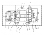
- Fig. 3 shows a compressor system according to the invention.
- the compressor system comprises a compressor 4 and a compressor cooling device 15.
- the compressor cooling device 15 is shown highly schematically and can specifically comprise cooling fluid channels (for example cooling fluid loops) which are arranged, for example, in a corresponding wall of a compressor housing 16 and/or on the outside and/or inside of a wall of the compressor housing 16.
- the compressor 4 comprises a displacer 17, an electric motor 18 and (control) electronics 19.
- the displacer is designed here as a scroll displacer, for example.
- Suction gas is introduced (sucked in) via a compressor inlet 20, compressed gas (hot gas) exits via a compressor outlet 21.
- the (suction) gas entering via the compressor inlet can either be passed through the electric motor 18 (in particular for cooling it) or passed through a bypass 22.
- a bypass valve 23 can be switched or controlled accordingly for this purpose. It is also possible to pass part of the sucked-in gas through the electric motor 18 and part of the gas (for example by corresponding partial opening or partial closing of the valve 23) through the bypass 22.
- the respective portion is particularly preferably controllable, in particular adjustable. Due to the (controllable and/or adjustable) bypass for the suction gas, the suction gas can be passed past the electric motor 18 (and thus passed directly to the displacer 17 without heating up). Alternatively, at least part of the suction gas or the entire suction gas flow can be passed through the electric motor 18. This enables an increase in efficiency by optimizing the operating conditions or operating temperatures in the relevant areas.
- the compressor cooling device 15 also comprises a first subsystem 24, a second subsystem 25 and a third subsystem 26.
- the first subsystem 24 can be used to cool the displacer 17 in particular, the second subsystem 25 to cool the electric motor 18 in particular and the third subsystem 26 to cool the (control) electronics 19 in particular.
- Each subsystem can preferably be operated independently of the other two subsystems, i.e., for example, the electric motor 18 can be cooled by the compressor cooling device 15 without the displacer 17 (via the corresponding subsystem 24) or the (control) electronics 19 (via the corresponding subsystem 26) being cooled. This enables further optimized operation, which increases efficiency.
- the subsystems (for additional cooling) can be controlled or regulated using individual (independent) pumps and/or valves.
Landscapes
- Engineering & Computer Science (AREA)
- Power Engineering (AREA)
- Mechanical Engineering (AREA)
- Transportation (AREA)
- General Chemical & Material Sciences (AREA)
- Chemical & Material Sciences (AREA)
- Electrochemistry (AREA)
- Chemical Kinetics & Catalysis (AREA)
- Manufacturing & Machinery (AREA)
- Life Sciences & Earth Sciences (AREA)
- Sustainable Development (AREA)
- Sustainable Energy (AREA)
- Air-Conditioning For Vehicles (AREA)
- Cooling, Air Intake And Gas Exhaust, And Fuel Tank Arrangements In Propulsion Units (AREA)
Claims (19)
- Système de compresseur électrique pour un véhicule, notamment à entraînement électrique, de préférence purement électrique, comprenant au moins un compresseur (4) à entraînement électrique servant à comprimer un fluide frigorigène ainsi qu'au moins un dispositif de refroidissement à compresseur (15) servant à refroidir le compresseur (4), un fluide de refroidissement, notamment un liquide de refroidissement, comprenant de préférence de l'eau, pouvant s'écouler dans le dispositif de refroidissement de compresseur (15), caractérisé en ce que le fluide de refroidissement est séparé du fluide frigorigène à comprimer par le compresseur (4), le fluide de refroidissement se distinguant dans sa composition matérielle du fluide frigorigène à comprimer.
- Système de compresseur selon la revendication 1, dans lequel un moteur électrique du compresseur (4) peut être refroidi au moins par une partie du fluide frigorigène à comprimer, une dérivation (22), notamment contrôlable ou réglable, étant prévue pour pouvoir faire passer au moins une partie du fluide frigorigène devant le moteur électrique (18).
- Système de compresseur selon la revendication 1 ou 2,
caractérisé en ce que
le fluide de refroidissement, notamment au moyen de plusieurs sous-systèmes de refroidissement (24, 25, 26), de préférence indépendants l'un de l'autre, permet de refroidir au moins deux composants du compresseur, de préférence un élément de refoulement (17), par exemple un défilement, et/ou un moteur électrique (18) et/ou une électronique (19) et/ou au moins un autre composant. - Système de compresseur selon l'une des revendications précédentes,
caractérisé en ce que
au moins une soupape et/ou au moins une pompe, de préférence au moins deux pompes, notamment indépendantes l'une de l'autre, est/sont prévue(s) pour commander, notamment pour régler, un refroidissement d'au moins deux sous-systèmes de refroidissement (24, 25, 26) du dispositif de refroidissement à compresseur (15). - Système de batterie pour un véhicule, notamment à entraînement électrique, de préférence purement électrique, comprenant au moins une batterie rechargeable (13) ainsi qu'au moins un système de compresseur selon l'une des revendications précédentes, pour le refroidissement actif de l'au moins une batterie (13).
- Système de batterie selon la revendication 5, pour un véhicule, notamment à entraînement électrique, de préférence purement électrique, comprenant au moins une batterie rechargeable (13) ainsi qu'au moins un composant actif, à savoir au moins un compresseur (4), un dispositif de refroidissement (12) pour le refroidissement actif de l'au moins une batterie (13), le composant actif formant, conjointement avec l'au moins une batterie (13), une unité modulaire (14) de telle sorte que le composant actif et au moins une batterie soient reliés entre eux de manière fixe ou rigide (directement ou indirectement ou par l'intermédiaire d'un dispositif de liaison rigide).
- Système de batterie selon la revendication 5 ou 6,
caractérisé en ce que
il est prévu au moins un dispositif de soutien, notamment un cadre de support (5), qui maintient l'au moins une batterie (13), notamment au moins un paquet d'accumulateurs (8), le composant actif, notamment le compresseur (4), étant disposé de préférence, notamment principalement ou exclusivement, sur l'au moins un dispositif de support. - Système de batterie selon l'une des revendications 5 à 7,
caractérisé en ce que
plusieurs batteries (13) sont disposées autour de l'au moins un composant actif, notamment de l'au moins un compresseur (4). - Système de batterie selon l'une des revendications précédentes 5 à 8,
caractérisé en ce que
l'au moins un composant actif, notamment l'au moins un compresseur (4), et/ou l'au moins une batterie (13) sont disposés dans un boîtier, notamment insonorisant acoustiquement et/ou absorbant le son à l'intérieur, le boîtier respectif étant le cas échéant un boîtier commun à l'au moins un composant actif, notamment à l'au moins un compresseur, et à l'au moins une batterie (13) ou étant un boîtier, notamment insonorisant acoustiquement et/ou absorbant le son à l'intérieur, qui ne contient que l'au moins un composant actif, notamment l'au moins un compresseur, ou que l'au moins une batterie (13). - Système de batterie selon l'une des revendications précédentes 5 à 9,
caractérisé en ce que
le compresseur placé éventuellement dans un boîtier acoustiquement isolant est relié à un circuit de refroidissement par au moins un guide de conduite, de sorte qu'au moins des parties extérieures du compresseur sont refroidies séparément en plus de son refroidissement intérieur. - Système de batterie selon l'une des revendications précédentes 5 à 9,
caractérisé en ce que
l'au moins un composant actif, notamment l'au moins un compresseur (4), est disposé au moins partiellement sur au moins un dispositif de support ou un palier pneumatique, insonorisant et/ou amortissant le bruit, notamment un dispositif insonorisant et/ou amortissant les bruits de structure, de préférence passif et/ou commutable et/ou actif sur le plan vibroacoustique. - Système de batterie selon l'une des revendications précédentes 5 à 11,
caractérisé en ce que
une, plusieurs ou toutes les lignes du système électrique de commande et/ou de puissance et/ou une, plusieurs, ou toutes les lignes de transport de fluide qui relient l'au moins un composant actif placé dans un boîtier de préférence insonorisé selon la revendication 9 à des composants à l'extérieur du boîtier insonorisé, sont fixées, de préférence individuellement ou en groupes, à des points rigides et/ou massifs, de préférence au dispositif de soutien selon la revendication 7, de préférence au moyen d'éléments de couplage insonorisant et/ou amortissant les bruits de structure. - Système de batterie selon l'une des revendications précédentes 5 à 12,
caractérisé en ce que
au moins un système électrique de commande (9) est prévu pour la batterie (13), de préférence en tant que partie intégrante de l'unité modulaire (14), l'au moins un composant actif, notamment l'au moins un compresseur (4), étant de préférence disposé au moins partiellement entre l'au moins une batterie (13) et le système électrique de commande (9), notamment un boîtier du système électrique de commande. - Utilisation d'un système de compresseur selon l'une des revendications précédentes 1 à 4 et/ou d'un système de batterie selon l'une des revendications précédentes 5 à 13 pour un véhicule, notamment à entraînement électrique, de préférence purement électrique.
- Véhicule, notamment à entraînement électrique, de préférence purement électrique, comprenant un système de compresseur selon l'une des revendications précédentes 1 à 4 et/ou un système de batterie selon l'une des revendications précédentes 5 à 13.
- Procédé pour faire fonctionner un système de compresseur selon l'une des revendications 1 à 4 et/ou un système de batterie selon l'une des revendications 5 à 13 et/ou un véhicule selon la revendication 15, dans lequel l'au moins un compresseur est refroidi par un fluide de refroidissement s'écoulant dans le dispositif de refroidissement à compresseur (15), notamment comprenant de l'eau.
- Procédé selon la revendication 16, en référence à au moins l'une des revendications 5 à 13, dans lequel, dans une première étape, on prépare ou on fabrique l'unité modulaire (14) comprenant l'au moins un composant actif, notamment l'au moins un compresseur (4), et l'au moins une batterie (13), et dans une étape ultérieure, on relie l'unité modulaire (14) aux composants restants du véhicule.
- Procédé selon la revendication 16 ou 17, pour faire fonctionner un système de compresseur selon l'une des revendications 1 à 4 et/ou un système de batterie selon l'une des revendications 5 à 13 et/ou un véhicule selon la revendication 15, dans lequel un moteur électrique (18) du compresseur (4) est refroidi au moins par une partie du fluide frigorigène à comprimer et/ou au moins une partie du fluide frigorigène passe devant le moteur électrique (18), notamment au choix, de préférence par un contrôle ou une régulation correspondante.
- Procédé selon l'une des revendications 16 à 18, pour faire fonctionner un système de batterie selon l'une des revendications 5 à 13 et/ou un véhicule selon la revendication 15, dans lequel l'au moins une batterie (13) et/ou la cabine du véhicule sont refroidies par l'au moins un dispositif de refroidissement (12) pendant la charge et/ou la décharge de celle-ci, notamment pendant le fonctionnement du véhicule.
Applications Claiming Priority (1)
| Application Number | Priority Date | Filing Date | Title |
|---|---|---|---|
| PCT/EP2019/086625 WO2021121621A1 (fr) | 2019-12-20 | 2019-12-20 | Système de compresseur et de batterie pour un véhicule automobile |
Publications (3)
| Publication Number | Publication Date |
|---|---|
| EP4077018A1 EP4077018A1 (fr) | 2022-10-26 |
| EP4077018B1 true EP4077018B1 (fr) | 2024-10-02 |
| EP4077018B8 EP4077018B8 (fr) | 2024-11-06 |
Family
ID=76478341
Family Applications (1)
| Application Number | Title | Priority Date | Filing Date |
|---|---|---|---|
| EP19836803.7A Active EP4077018B8 (fr) | 2019-12-20 | 2019-12-20 | Système de compresseur et de batterie pour un véhicule |
Country Status (3)
| Country | Link |
|---|---|
| EP (1) | EP4077018B8 (fr) |
| ES (1) | ES2998458T3 (fr) |
| WO (1) | WO2021121621A1 (fr) |
Families Citing this family (1)
| Publication number | Priority date | Publication date | Assignee | Title |
|---|---|---|---|---|
| CN114919431B (zh) * | 2022-05-23 | 2024-03-22 | 东风柳州汽车有限公司 | 汽车电池配电盒及汽车动力电池包 |
Citations (5)
| Publication number | Priority date | Publication date | Assignee | Title |
|---|---|---|---|---|
| DE102009054186A1 (de) * | 2009-11-23 | 2011-05-26 | Behr Gmbh & Co. Kg | System für ein Kraftfahrzeug zum Erwärmen und/oder Kühlen einer Batterie und eines Kraftfahrzeuginnenraumes |
| US20120003515A1 (en) * | 2010-06-30 | 2012-01-05 | Nissan Technical Center North America, Inc. | Vehicle battery temperature control system and method |
| US20120222438A1 (en) * | 2009-11-30 | 2012-09-06 | Hitachi, Ltd. | Air-Conditioning System for a Vehicle |
| DE102016108468A1 (de) * | 2015-05-26 | 2016-12-01 | Ford Global Technologies, Llc | Kühlmodi für das management einer hochspannungsbatterie für ein fahrzeug |
| US20180086224A1 (en) * | 2016-09-27 | 2018-03-29 | Rivian Automotive, LLC | Electric vehicle thermal management system with battery heat storage |
Family Cites Families (1)
| Publication number | Priority date | Publication date | Assignee | Title |
|---|---|---|---|---|
| US9527403B2 (en) | 2014-04-29 | 2016-12-27 | Tesla Motors, Inc. | Charging station providing thermal conditioning of electric vehicle during charging session |
-
2019
- 2019-12-20 WO PCT/EP2019/086625 patent/WO2021121621A1/fr not_active Ceased
- 2019-12-20 ES ES19836803T patent/ES2998458T3/es active Active
- 2019-12-20 EP EP19836803.7A patent/EP4077018B8/fr active Active
Patent Citations (5)
| Publication number | Priority date | Publication date | Assignee | Title |
|---|---|---|---|---|
| DE102009054186A1 (de) * | 2009-11-23 | 2011-05-26 | Behr Gmbh & Co. Kg | System für ein Kraftfahrzeug zum Erwärmen und/oder Kühlen einer Batterie und eines Kraftfahrzeuginnenraumes |
| US20120222438A1 (en) * | 2009-11-30 | 2012-09-06 | Hitachi, Ltd. | Air-Conditioning System for a Vehicle |
| US20120003515A1 (en) * | 2010-06-30 | 2012-01-05 | Nissan Technical Center North America, Inc. | Vehicle battery temperature control system and method |
| DE102016108468A1 (de) * | 2015-05-26 | 2016-12-01 | Ford Global Technologies, Llc | Kühlmodi für das management einer hochspannungsbatterie für ein fahrzeug |
| US20180086224A1 (en) * | 2016-09-27 | 2018-03-29 | Rivian Automotive, LLC | Electric vehicle thermal management system with battery heat storage |
Also Published As
| Publication number | Publication date |
|---|---|
| EP4077018A1 (fr) | 2022-10-26 |
| ES2998458T3 (en) | 2025-02-20 |
| WO2021121621A1 (fr) | 2021-06-24 |
| EP4077018B8 (fr) | 2024-11-06 |
Similar Documents
| Publication | Publication Date | Title |
|---|---|---|
| DE102016006682B4 (de) | Verfahren zum Betreiben einer Klimaanlage eines Elektro- oder Hybridfahrzeugs sowie Klimaanlage zur Durchführung des Verfahrens | |
| DE102014117542B4 (de) | Kühlsystem für fahrzeug | |
| DE102005026677B4 (de) | Kühlsystem zur Verwendung in einem Hybrid-Getriebenen Automobil | |
| EP1995425B1 (fr) | Module de chargement intégré | |
| DE102015108611A1 (de) | Fahrzeugkomponente | |
| EP2058504B1 (fr) | Moteur à combustion interne doté d'un refroidisseur de soupape de recyclage des gaz d'échappement | |
| EP2471136A1 (fr) | Véhicule présentant au moins un circuit de refroidissement permettant de refroidir un système de piles à combustible | |
| DE102019128941B4 (de) | Front-Stoßfänger mit integriertem Wärmetauscher | |
| EP2393688A2 (fr) | Groupe électrogène | |
| WO2021048109A1 (fr) | Dispositif de refroidissement pour véhicule automobile | |
| DE102009023175B4 (de) | Verfahren zum Betreiben eines Kraftfahrzeugs mit Abwärmeheizung | |
| WO2018210363A1 (fr) | Appareil de gestion de température pour batteries de véhicules | |
| EP4077018B1 (fr) | Système de compresseur et de batterie pour un véhicule | |
| DE102018215836A1 (de) | Modulare Aufdachklimaanlage | |
| DE102011010451A1 (de) | Fahrzeug mit einer elektrochemischen Energiespeichereinheit | |
| DE10209237B4 (de) | Luftgekühltes Frontkühlermodul | |
| DE102015008942A1 (de) | Temperiervorrichtung für eine elektrische Batterie und Fahrzeug | |
| DE102009036456A1 (de) | Kraftwagen | |
| DE102018116312A1 (de) | Batterie-System für ein Kraftfahrzeug | |
| EP2006508A2 (fr) | Unité d'alimentation dotée d'un agrégat de générateur/moteur en tant que générateur de courant | |
| DE102010010398A1 (de) | Frontstruktur eines Kraftfahrzeugs | |
| DE102004025831B4 (de) | Kraftfahrzeug mit einer kühlbaren elektrischen Speichereinrichtung | |
| WO2023285020A1 (fr) | Module central d'un véhicule électrique et véhicule électrique | |
| EP4392279A1 (fr) | Unité de refroidissement de chaîne cinématique pour un véhicule | |
| DE102018104831A1 (de) | Lüfteranordnung für ein Kraftfahrzeug |
Legal Events
| Date | Code | Title | Description |
|---|---|---|---|
| STAA | Information on the status of an ep patent application or granted ep patent |
Free format text: STATUS: UNKNOWN |
|
| STAA | Information on the status of an ep patent application or granted ep patent |
Free format text: STATUS: THE INTERNATIONAL PUBLICATION HAS BEEN MADE |
|
| PUAI | Public reference made under article 153(3) epc to a published international application that has entered the european phase |
Free format text: ORIGINAL CODE: 0009012 |
|
| STAA | Information on the status of an ep patent application or granted ep patent |
Free format text: STATUS: REQUEST FOR EXAMINATION WAS MADE |
|
| 17P | Request for examination filed |
Effective date: 20220323 |
|
| AK | Designated contracting states |
Kind code of ref document: A1 Designated state(s): AL AT BE BG CH CY CZ DE DK EE ES FI FR GB GR HR HU IE IS IT LI LT LU LV MC MK MT NL NO PL PT RO RS SE SI SK SM TR |
|
| DAV | Request for validation of the european patent (deleted) | ||
| DAX | Request for extension of the european patent (deleted) | ||
| P01 | Opt-out of the competence of the unified patent court (upc) registered |
Effective date: 20230531 |
|
| STAA | Information on the status of an ep patent application or granted ep patent |
Free format text: STATUS: EXAMINATION IS IN PROGRESS |
|
| 17Q | First examination report despatched |
Effective date: 20231012 |
|
| GRAP | Despatch of communication of intention to grant a patent |
Free format text: ORIGINAL CODE: EPIDOSNIGR1 |
|
| STAA | Information on the status of an ep patent application or granted ep patent |
Free format text: STATUS: GRANT OF PATENT IS INTENDED |
|
| RIC1 | Information provided on ipc code assigned before grant |
Ipc: H01M 10/625 20140101ALI20240403BHEP Ipc: H01M 10/613 20140101ALI20240403BHEP Ipc: H01M 10/66 20140101ALI20240403BHEP Ipc: B60L 50/64 20190101ALI20240403BHEP Ipc: B60K 1/04 20190101ALI20240403BHEP Ipc: B60H 1/00 20060101ALI20240403BHEP Ipc: B60K 11/02 20060101ALI20240403BHEP Ipc: H01M 50/20 20210101ALI20240403BHEP Ipc: B60L 50/60 20190101ALI20240403BHEP Ipc: B60K 1/00 20060101ALI20240403BHEP Ipc: B60L 58/26 20190101ALI20240403BHEP Ipc: B60L 1/00 20060101ALI20240403BHEP Ipc: B60L 1/02 20060101AFI20240403BHEP |
|
| INTG | Intention to grant announced |
Effective date: 20240423 |
|
| GRAS | Grant fee paid |
Free format text: ORIGINAL CODE: EPIDOSNIGR3 |
|
| GRAA | (expected) grant |
Free format text: ORIGINAL CODE: 0009210 |
|
| STAA | Information on the status of an ep patent application or granted ep patent |
Free format text: STATUS: THE PATENT HAS BEEN GRANTED |
|
| GRAT | Correction requested after decision to grant or after decision to maintain patent in amended form |
Free format text: ORIGINAL CODE: EPIDOSNCDEC |
|
| AK | Designated contracting states |
Kind code of ref document: B1 Designated state(s): AL AT BE BG CH CY CZ DE DK EE ES FI FR GB GR HR HU IE IS IT LI LT LU LV MC MK MT NL NO PL PT RO RS SE SI SK SM TR |
|
| REG | Reference to a national code |
Ref country code: GB Ref legal event code: FG4D Free format text: NOT ENGLISH |
|
| REG | Reference to a national code |
Ref country code: CH Ref legal event code: PK Free format text: BERICHTIGUNG B8 Ref country code: CH Ref legal event code: EP |
|
| REG | Reference to a national code |
Ref country code: DE Ref legal event code: R096 Ref document number: 502019012239 Country of ref document: DE |
|
| REG | Reference to a national code |
Ref country code: IE Ref legal event code: FG4D Free format text: LANGUAGE OF EP DOCUMENT: GERMAN |
|
| RIN2 | Information on inventor provided after grant (corrected) |
Inventor name: HARTMANN, THOMAS Inventor name: ZIPP, WALTER |
|
| REG | Reference to a national code |
Ref country code: LT Ref legal event code: MG9D |
|
| REG | Reference to a national code |
Ref country code: NL Ref legal event code: MP Effective date: 20241002 |
|
| REG | Reference to a national code |
Ref country code: ES Ref legal event code: FG2A Ref document number: 2998458 Country of ref document: ES Kind code of ref document: T3 Effective date: 20250220 |
|
| PG25 | Lapsed in a contracting state [announced via postgrant information from national office to epo] |
Ref country code: NL Free format text: LAPSE BECAUSE OF FAILURE TO SUBMIT A TRANSLATION OF THE DESCRIPTION OR TO PAY THE FEE WITHIN THE PRESCRIBED TIME-LIMIT Effective date: 20241002 |
|
| PG25 | Lapsed in a contracting state [announced via postgrant information from national office to epo] |
Ref country code: NL Free format text: LAPSE BECAUSE OF FAILURE TO SUBMIT A TRANSLATION OF THE DESCRIPTION OR TO PAY THE FEE WITHIN THE PRESCRIBED TIME-LIMIT Effective date: 20241002 |
|
| PG25 | Lapsed in a contracting state [announced via postgrant information from national office to epo] |
Ref country code: HR Free format text: LAPSE BECAUSE OF FAILURE TO SUBMIT A TRANSLATION OF THE DESCRIPTION OR TO PAY THE FEE WITHIN THE PRESCRIBED TIME-LIMIT Effective date: 20241002 Ref country code: IS Free format text: LAPSE BECAUSE OF FAILURE TO SUBMIT A TRANSLATION OF THE DESCRIPTION OR TO PAY THE FEE WITHIN THE PRESCRIBED TIME-LIMIT Effective date: 20250202 Ref country code: PT Free format text: LAPSE BECAUSE OF FAILURE TO SUBMIT A TRANSLATION OF THE DESCRIPTION OR TO PAY THE FEE WITHIN THE PRESCRIBED TIME-LIMIT Effective date: 20250203 |
|
| PG25 | Lapsed in a contracting state [announced via postgrant information from national office to epo] |
Ref country code: FI Free format text: LAPSE BECAUSE OF FAILURE TO SUBMIT A TRANSLATION OF THE DESCRIPTION OR TO PAY THE FEE WITHIN THE PRESCRIBED TIME-LIMIT Effective date: 20241002 |
|
| PG25 | Lapsed in a contracting state [announced via postgrant information from national office to epo] |
Ref country code: BG Free format text: LAPSE BECAUSE OF FAILURE TO SUBMIT A TRANSLATION OF THE DESCRIPTION OR TO PAY THE FEE WITHIN THE PRESCRIBED TIME-LIMIT Effective date: 20241002 |
|
| PG25 | Lapsed in a contracting state [announced via postgrant information from national office to epo] |
Ref country code: NO Free format text: LAPSE BECAUSE OF FAILURE TO SUBMIT A TRANSLATION OF THE DESCRIPTION OR TO PAY THE FEE WITHIN THE PRESCRIBED TIME-LIMIT Effective date: 20250102 |
|
| PG25 | Lapsed in a contracting state [announced via postgrant information from national office to epo] |
Ref country code: LV Free format text: LAPSE BECAUSE OF FAILURE TO SUBMIT A TRANSLATION OF THE DESCRIPTION OR TO PAY THE FEE WITHIN THE PRESCRIBED TIME-LIMIT Effective date: 20241002 Ref country code: GR Free format text: LAPSE BECAUSE OF FAILURE TO SUBMIT A TRANSLATION OF THE DESCRIPTION OR TO PAY THE FEE WITHIN THE PRESCRIBED TIME-LIMIT Effective date: 20250103 |
|
| PG25 | Lapsed in a contracting state [announced via postgrant information from national office to epo] |
Ref country code: PL Free format text: LAPSE BECAUSE OF FAILURE TO SUBMIT A TRANSLATION OF THE DESCRIPTION OR TO PAY THE FEE WITHIN THE PRESCRIBED TIME-LIMIT Effective date: 20241002 Ref country code: CZ Free format text: LAPSE BECAUSE OF FAILURE TO SUBMIT A TRANSLATION OF THE DESCRIPTION OR TO PAY THE FEE WITHIN THE PRESCRIBED TIME-LIMIT Effective date: 20241002 |
|
| PG25 | Lapsed in a contracting state [announced via postgrant information from national office to epo] |
Ref country code: RS Free format text: LAPSE BECAUSE OF FAILURE TO SUBMIT A TRANSLATION OF THE DESCRIPTION OR TO PAY THE FEE WITHIN THE PRESCRIBED TIME-LIMIT Effective date: 20250102 |
|
| PG25 | Lapsed in a contracting state [announced via postgrant information from national office to epo] |
Ref country code: SM Free format text: LAPSE BECAUSE OF FAILURE TO SUBMIT A TRANSLATION OF THE DESCRIPTION OR TO PAY THE FEE WITHIN THE PRESCRIBED TIME-LIMIT Effective date: 20241002 |
|
| REG | Reference to a national code |
Ref country code: DE Ref legal event code: R097 Ref document number: 502019012239 Country of ref document: DE |
|
| PG25 | Lapsed in a contracting state [announced via postgrant information from national office to epo] |
Ref country code: MC Free format text: LAPSE BECAUSE OF FAILURE TO SUBMIT A TRANSLATION OF THE DESCRIPTION OR TO PAY THE FEE WITHIN THE PRESCRIBED TIME-LIMIT Effective date: 20241002 |
|
| PG25 | Lapsed in a contracting state [announced via postgrant information from national office to epo] |
Ref country code: DK Free format text: LAPSE BECAUSE OF FAILURE TO SUBMIT A TRANSLATION OF THE DESCRIPTION OR TO PAY THE FEE WITHIN THE PRESCRIBED TIME-LIMIT Effective date: 20241002 |
|
| PG25 | Lapsed in a contracting state [announced via postgrant information from national office to epo] |
Ref country code: RO Free format text: LAPSE BECAUSE OF FAILURE TO SUBMIT A TRANSLATION OF THE DESCRIPTION OR TO PAY THE FEE WITHIN THE PRESCRIBED TIME-LIMIT Effective date: 20241002 |
|
| PG25 | Lapsed in a contracting state [announced via postgrant information from national office to epo] |
Ref country code: SK Free format text: LAPSE BECAUSE OF FAILURE TO SUBMIT A TRANSLATION OF THE DESCRIPTION OR TO PAY THE FEE WITHIN THE PRESCRIBED TIME-LIMIT Effective date: 20241002 |
|
| REG | Reference to a national code |
Ref country code: CH Ref legal event code: PL |
|
| PLBE | No opposition filed within time limit |
Free format text: ORIGINAL CODE: 0009261 |
|
| STAA | Information on the status of an ep patent application or granted ep patent |
Free format text: STATUS: NO OPPOSITION FILED WITHIN TIME LIMIT |
|
| PG25 | Lapsed in a contracting state [announced via postgrant information from national office to epo] |
Ref country code: LU Free format text: LAPSE BECAUSE OF NON-PAYMENT OF DUE FEES Effective date: 20241220 |
|
| PG25 | Lapsed in a contracting state [announced via postgrant information from national office to epo] |
Ref country code: SE Free format text: LAPSE BECAUSE OF FAILURE TO SUBMIT A TRANSLATION OF THE DESCRIPTION OR TO PAY THE FEE WITHIN THE PRESCRIBED TIME-LIMIT Effective date: 20241002 |
|
| 26N | No opposition filed |
Effective date: 20250703 |
|
| REG | Reference to a national code |
Ref country code: BE Ref legal event code: MM Effective date: 20241231 |
|
| PG25 | Lapsed in a contracting state [announced via postgrant information from national office to epo] |
Ref country code: BE Free format text: LAPSE BECAUSE OF NON-PAYMENT OF DUE FEES Effective date: 20241231 |
|
| PG25 | Lapsed in a contracting state [announced via postgrant information from national office to epo] |
Ref country code: CH Free format text: LAPSE BECAUSE OF NON-PAYMENT OF DUE FEES Effective date: 20241231 |
|
| PG25 | Lapsed in a contracting state [announced via postgrant information from national office to epo] |
Ref country code: IE Free format text: LAPSE BECAUSE OF NON-PAYMENT OF DUE FEES Effective date: 20241220 |
|
| PGFP | Annual fee paid to national office [announced via postgrant information from national office to epo] |
Ref country code: DE Payment date: 20251211 Year of fee payment: 7 |
|
| PGFP | Annual fee paid to national office [announced via postgrant information from national office to epo] |
Ref country code: GB Payment date: 20251219 Year of fee payment: 7 |
|
| PGFP | Annual fee paid to national office [announced via postgrant information from national office to epo] |
Ref country code: IT Payment date: 20251223 Year of fee payment: 7 |
|
| PGFP | Annual fee paid to national office [announced via postgrant information from national office to epo] |
Ref country code: FR Payment date: 20251229 Year of fee payment: 7 |
|
| REG | Reference to a national code |
Ref country code: AT Ref legal event code: MM01 Ref document number: 1728234 Country of ref document: AT Kind code of ref document: T Effective date: 20241220 |
|
| PGFP | Annual fee paid to national office [announced via postgrant information from national office to epo] |
Ref country code: ES Payment date: 20260130 Year of fee payment: 7 |
|
| PG25 | Lapsed in a contracting state [announced via postgrant information from national office to epo] |
Ref country code: AT Free format text: LAPSE BECAUSE OF NON-PAYMENT OF DUE FEES Effective date: 20241220 |