EP4077077B1 - Méthode et système de régulation du glissement relatif d'une roue de véhicule - Google Patents
Méthode et système de régulation du glissement relatif d'une roue de véhicule Download PDFInfo
- Publication number
- EP4077077B1 EP4077077B1 EP20817278.3A EP20817278A EP4077077B1 EP 4077077 B1 EP4077077 B1 EP 4077077B1 EP 20817278 A EP20817278 A EP 20817278A EP 4077077 B1 EP4077077 B1 EP 4077077B1
- Authority
- EP
- European Patent Office
- Prior art keywords
- slip
- wheel
- control
- drive
- torque
- Prior art date
- Legal status (The legal status is an assumption and is not a legal conclusion. Google has not performed a legal analysis and makes no representation as to the accuracy of the status listed.)
- Active
Links
Images


Classifications
-
- B—PERFORMING OPERATIONS; TRANSPORTING
- B60—VEHICLES IN GENERAL
- B60W—CONJOINT CONTROL OF VEHICLE SUB-UNITS OF DIFFERENT TYPE OR DIFFERENT FUNCTION; CONTROL SYSTEMS SPECIALLY ADAPTED FOR HYBRID VEHICLES; ROAD VEHICLE DRIVE CONTROL SYSTEMS FOR PURPOSES NOT RELATED TO THE CONTROL OF A PARTICULAR SUB-UNIT
- B60W30/00—Purposes of road vehicle drive control systems not related to the control of a particular sub-unit, e.g. of systems using conjoint control of vehicle sub-units
- B60W30/18—Propelling the vehicle
- B60W30/18172—Preventing, or responsive to skidding of wheels
-
- B—PERFORMING OPERATIONS; TRANSPORTING
- B60—VEHICLES IN GENERAL
- B60T—VEHICLE BRAKE CONTROL SYSTEMS OR PARTS THEREOF; BRAKE CONTROL SYSTEMS OR PARTS THEREOF, IN GENERAL; ARRANGEMENT OF BRAKING ELEMENTS ON VEHICLES IN GENERAL; PORTABLE DEVICES FOR PREVENTING UNWANTED MOVEMENT OF VEHICLES; VEHICLE MODIFICATIONS TO FACILITATE COOLING OF BRAKES
- B60T8/00—Arrangements for adjusting wheel-braking force to meet varying vehicular or ground-surface conditions, e.g. limiting or varying distribution of braking force
- B60T8/17—Using electrical or electronic regulation means to control braking
- B60T8/175—Brake regulation specially adapted to prevent excessive wheel spin during vehicle acceleration, e.g. for traction control
-
- B—PERFORMING OPERATIONS; TRANSPORTING
- B60—VEHICLES IN GENERAL
- B60K—ARRANGEMENT OR MOUNTING OF PROPULSION UNITS OR OF TRANSMISSIONS IN VEHICLES; ARRANGEMENT OR MOUNTING OF PLURAL DIVERSE PRIME-MOVERS IN VEHICLES; AUXILIARY DRIVES FOR VEHICLES; INSTRUMENTATION OR DASHBOARDS FOR VEHICLES; ARRANGEMENTS IN CONNECTION WITH COOLING, AIR INTAKE, GAS EXHAUST OR FUEL SUPPLY OF PROPULSION UNITS IN VEHICLES
- B60K28/00—Safety devices for propulsion-unit control, specially adapted for, or arranged in, vehicles, e.g. preventing fuel supply or ignition in the event of potentially dangerous conditions
- B60K28/10—Safety devices for propulsion-unit control, specially adapted for, or arranged in, vehicles, e.g. preventing fuel supply or ignition in the event of potentially dangerous conditions responsive to conditions relating to the vehicle
- B60K28/16—Safety devices for propulsion-unit control, specially adapted for, or arranged in, vehicles, e.g. preventing fuel supply or ignition in the event of potentially dangerous conditions responsive to conditions relating to the vehicle responsive to, or preventing, spinning or skidding of wheels
-
- B—PERFORMING OPERATIONS; TRANSPORTING
- B60—VEHICLES IN GENERAL
- B60L—PROPULSION OF ELECTRICALLY-PROPELLED VEHICLES; SUPPLYING ELECTRIC POWER FOR AUXILIARY EQUIPMENT OF ELECTRICALLY-PROPELLED VEHICLES; ELECTRODYNAMIC BRAKE SYSTEMS FOR VEHICLES IN GENERAL; MAGNETIC SUSPENSION OR LEVITATION FOR VEHICLES; MONITORING OPERATING VARIABLES OF ELECTRICALLY-PROPELLED VEHICLES; ELECTRIC SAFETY DEVICES FOR ELECTRICALLY-PROPELLED VEHICLES
- B60L3/00—Electric devices on electrically-propelled vehicles for safety purposes; Monitoring operating variables, e.g. speed, deceleration or energy consumption
- B60L3/10—Indicating wheel slip ; Correction of wheel slip
- B60L3/102—Indicating wheel slip ; Correction of wheel slip of individual wheels
-
- B—PERFORMING OPERATIONS; TRANSPORTING
- B60—VEHICLES IN GENERAL
- B60L—PROPULSION OF ELECTRICALLY-PROPELLED VEHICLES; SUPPLYING ELECTRIC POWER FOR AUXILIARY EQUIPMENT OF ELECTRICALLY-PROPELLED VEHICLES; ELECTRODYNAMIC BRAKE SYSTEMS FOR VEHICLES IN GENERAL; MAGNETIC SUSPENSION OR LEVITATION FOR VEHICLES; MONITORING OPERATING VARIABLES OF ELECTRICALLY-PROPELLED VEHICLES; ELECTRIC SAFETY DEVICES FOR ELECTRICALLY-PROPELLED VEHICLES
- B60L3/00—Electric devices on electrically-propelled vehicles for safety purposes; Monitoring operating variables, e.g. speed, deceleration or energy consumption
- B60L3/10—Indicating wheel slip ; Correction of wheel slip
- B60L3/106—Indicating wheel slip ; Correction of wheel slip for maintaining or recovering the adhesion of the drive wheels
-
- B—PERFORMING OPERATIONS; TRANSPORTING
- B60—VEHICLES IN GENERAL
- B60T—VEHICLE BRAKE CONTROL SYSTEMS OR PARTS THEREOF; BRAKE CONTROL SYSTEMS OR PARTS THEREOF, IN GENERAL; ARRANGEMENT OF BRAKING ELEMENTS ON VEHICLES IN GENERAL; PORTABLE DEVICES FOR PREVENTING UNWANTED MOVEMENT OF VEHICLES; VEHICLE MODIFICATIONS TO FACILITATE COOLING OF BRAKES
- B60T8/00—Arrangements for adjusting wheel-braking force to meet varying vehicular or ground-surface conditions, e.g. limiting or varying distribution of braking force
- B60T8/17—Using electrical or electronic regulation means to control braking
- B60T8/1755—Brake regulation specially adapted to control the stability of the vehicle, e.g. taking into account yaw rate or transverse acceleration in a curve
-
- B—PERFORMING OPERATIONS; TRANSPORTING
- B60—VEHICLES IN GENERAL
- B60T—VEHICLE BRAKE CONTROL SYSTEMS OR PARTS THEREOF; BRAKE CONTROL SYSTEMS OR PARTS THEREOF, IN GENERAL; ARRANGEMENT OF BRAKING ELEMENTS ON VEHICLES IN GENERAL; PORTABLE DEVICES FOR PREVENTING UNWANTED MOVEMENT OF VEHICLES; VEHICLE MODIFICATIONS TO FACILITATE COOLING OF BRAKES
- B60T8/00—Arrangements for adjusting wheel-braking force to meet varying vehicular or ground-surface conditions, e.g. limiting or varying distribution of braking force
- B60T8/17—Using electrical or electronic regulation means to control braking
- B60T8/176—Brake regulation specially adapted to prevent excessive wheel slip during vehicle deceleration, e.g. ABS
- B60T8/1761—Brake regulation specially adapted to prevent excessive wheel slip during vehicle deceleration, e.g. ABS responsive to wheel or brake dynamics, e.g. wheel slip, wheel acceleration or rate of change of brake fluid pressure
- B60T8/17616—Microprocessor-based systems
-
- B—PERFORMING OPERATIONS; TRANSPORTING
- B60—VEHICLES IN GENERAL
- B60W—CONJOINT CONTROL OF VEHICLE SUB-UNITS OF DIFFERENT TYPE OR DIFFERENT FUNCTION; CONTROL SYSTEMS SPECIALLY ADAPTED FOR HYBRID VEHICLES; ROAD VEHICLE DRIVE CONTROL SYSTEMS FOR PURPOSES NOT RELATED TO THE CONTROL OF A PARTICULAR SUB-UNIT
- B60W10/00—Conjoint control of vehicle sub-units of different type or different function
- B60W10/04—Conjoint control of vehicle sub-units of different type or different function including control of propulsion units
- B60W10/08—Conjoint control of vehicle sub-units of different type or different function including control of propulsion units including control of electric propulsion units, e.g. motors or generators
-
- B—PERFORMING OPERATIONS; TRANSPORTING
- B60—VEHICLES IN GENERAL
- B60W—CONJOINT CONTROL OF VEHICLE SUB-UNITS OF DIFFERENT TYPE OR DIFFERENT FUNCTION; CONTROL SYSTEMS SPECIALLY ADAPTED FOR HYBRID VEHICLES; ROAD VEHICLE DRIVE CONTROL SYSTEMS FOR PURPOSES NOT RELATED TO THE CONTROL OF A PARTICULAR SUB-UNIT
- B60W10/00—Conjoint control of vehicle sub-units of different type or different function
- B60W10/18—Conjoint control of vehicle sub-units of different type or different function including control of braking systems
- B60W10/184—Conjoint control of vehicle sub-units of different type or different function including control of braking systems with wheel brakes
-
- B—PERFORMING OPERATIONS; TRANSPORTING
- B60—VEHICLES IN GENERAL
- B60T—VEHICLE BRAKE CONTROL SYSTEMS OR PARTS THEREOF; BRAKE CONTROL SYSTEMS OR PARTS THEREOF, IN GENERAL; ARRANGEMENT OF BRAKING ELEMENTS ON VEHICLES IN GENERAL; PORTABLE DEVICES FOR PREVENTING UNWANTED MOVEMENT OF VEHICLES; VEHICLE MODIFICATIONS TO FACILITATE COOLING OF BRAKES
- B60T2230/00—Monitoring, detecting special vehicle behaviour; Counteracting thereof
- B60T2230/02—Side slip angle, attitude angle, floating angle, drift angle
-
- B—PERFORMING OPERATIONS; TRANSPORTING
- B60—VEHICLES IN GENERAL
- B60W—CONJOINT CONTROL OF VEHICLE SUB-UNITS OF DIFFERENT TYPE OR DIFFERENT FUNCTION; CONTROL SYSTEMS SPECIALLY ADAPTED FOR HYBRID VEHICLES; ROAD VEHICLE DRIVE CONTROL SYSTEMS FOR PURPOSES NOT RELATED TO THE CONTROL OF A PARTICULAR SUB-UNIT
- B60W2520/00—Input parameters relating to overall vehicle dynamics
- B60W2520/10—Longitudinal speed
-
- B—PERFORMING OPERATIONS; TRANSPORTING
- B60—VEHICLES IN GENERAL
- B60W—CONJOINT CONTROL OF VEHICLE SUB-UNITS OF DIFFERENT TYPE OR DIFFERENT FUNCTION; CONTROL SYSTEMS SPECIALLY ADAPTED FOR HYBRID VEHICLES; ROAD VEHICLE DRIVE CONTROL SYSTEMS FOR PURPOSES NOT RELATED TO THE CONTROL OF A PARTICULAR SUB-UNIT
- B60W2520/00—Input parameters relating to overall vehicle dynamics
- B60W2520/28—Wheel speed
-
- B—PERFORMING OPERATIONS; TRANSPORTING
- B60—VEHICLES IN GENERAL
- B60W—CONJOINT CONTROL OF VEHICLE SUB-UNITS OF DIFFERENT TYPE OR DIFFERENT FUNCTION; CONTROL SYSTEMS SPECIALLY ADAPTED FOR HYBRID VEHICLES; ROAD VEHICLE DRIVE CONTROL SYSTEMS FOR PURPOSES NOT RELATED TO THE CONTROL OF A PARTICULAR SUB-UNIT
- B60W2710/00—Output or target parameters relating to a particular sub-units
- B60W2710/08—Electric propulsion units
- B60W2710/083—Torque
-
- B—PERFORMING OPERATIONS; TRANSPORTING
- B60—VEHICLES IN GENERAL
- B60W—CONJOINT CONTROL OF VEHICLE SUB-UNITS OF DIFFERENT TYPE OR DIFFERENT FUNCTION; CONTROL SYSTEMS SPECIALLY ADAPTED FOR HYBRID VEHICLES; ROAD VEHICLE DRIVE CONTROL SYSTEMS FOR PURPOSES NOT RELATED TO THE CONTROL OF A PARTICULAR SUB-UNIT
- B60W2710/00—Output or target parameters relating to a particular sub-units
- B60W2710/18—Braking system
-
- B—PERFORMING OPERATIONS; TRANSPORTING
- B60—VEHICLES IN GENERAL
- B60W—CONJOINT CONTROL OF VEHICLE SUB-UNITS OF DIFFERENT TYPE OR DIFFERENT FUNCTION; CONTROL SYSTEMS SPECIALLY ADAPTED FOR HYBRID VEHICLES; ROAD VEHICLE DRIVE CONTROL SYSTEMS FOR PURPOSES NOT RELATED TO THE CONTROL OF A PARTICULAR SUB-UNIT
- B60W2720/00—Output or target parameters relating to overall vehicle dynamics
- B60W2720/26—Wheel slip
-
- Y—GENERAL TAGGING OF NEW TECHNOLOGICAL DEVELOPMENTS; GENERAL TAGGING OF CROSS-SECTIONAL TECHNOLOGIES SPANNING OVER SEVERAL SECTIONS OF THE IPC; TECHNICAL SUBJECTS COVERED BY FORMER USPC CROSS-REFERENCE ART COLLECTIONS [XRACs] AND DIGESTS
- Y02—TECHNOLOGIES OR APPLICATIONS FOR MITIGATION OR ADAPTATION AGAINST CLIMATE CHANGE
- Y02T—CLIMATE CHANGE MITIGATION TECHNOLOGIES RELATED TO TRANSPORTATION
- Y02T10/00—Road transport of goods or passengers
- Y02T10/60—Other road transportation technologies with climate change mitigation effect
- Y02T10/72—Electric energy management in electromobility
Definitions
- the invention relates to a method and a device for slip control of a vehicle wheel driven via an electric drive.
- Electricly driven vehicles with an electric drive that acts directly on the individual wheels enable individual control of the individual vehicle wheels, which is also known as wheel drive.
- the electric drive can be used to brake the wheels with recuperation or recovery of the kinetic energy as electrical energy.
- the electric drive can act on the wheel directly or through a gear.
- a friction brake is generally provided, which is designed as a pneumatic brake in commercial vehicles.
- Instabilities can occur in particular if greater longitudinal and lateral forces are to be transmitted in a driving situation than the coefficient of friction between the tire and the road allows.
- an ABS intervention is generally carried out on the wheel, during which a tendency to lock is detected, so that blocking of the wheel is prevented by suitable control of the friction brake, taking into account a maximum permissible slip value.
- the wheel-specific braking force can be adjusted and the wheel slip can be regulated to a suitable slip value at which maximum force can be transmitted between the wheel and the road.
- Such a method thus improves the steering ability, i.e. H. Transmission of a transverse force, maintained.
- the DE 10 2017 211 436 A1 describes a method and a device for controlling an electric motor for a vehicle, in which a target speed value representing a target speed of the electric motor is changed by a speed step and the torque provided by the electric motor is thereby detected.
- a target speed value representing a target speed of the electric motor is changed by a speed step and the torque provided by the electric motor is thereby detected.
- this can cause problems with lateral guidance in particular; Furthermore, this may result in wheel speeds being set that are not adapted to the speed level.
- the DE 10 2011 100 814 A1 relates to a device for traction control for a vehicle with an electric vehicle drive, in which the electric drive motors of the wheels are each fed by a controllable converter, with an ASR control device informing each converter of the maximum permissible speed of the relevant drive motor for speed control. Such a control can therefore limit traction slip in particular.
- the DE 10 2010 003 076 A1 describes a method and system for controlling wheel brake slip for a vehicle with an electric drive, in which a brake signal is detected by a slip control device and an electric drive control device and a friction brake control device are then controlled. Regenerative braking can thus be carried out taking wheel slip into account.
- the US 2004/0176899 A shows a control of the torques applied to a plurality of wheels of a motor vehicle, wherein speed sensors and a yaw rate acceleration sensor are provided.
- the required torques to be exerted on the respective wheels on laterally opposite sides of the vehicle are determined in order to regulate the wheel slip and generate a correction torque about the yaw axis of the vehicle.
- target values desired by the driver can be taken into account for the control.
- a control for braking forces and driving forces of a vehicle in which the driver's request is recorded and a target braking/driving force and a target yaw moment are determined, which are to be generated via the braking/driving forces that are to be exerted on the tires.
- a yaw rate sensor is provided for this purpose.
- the EP 2 612 716 B1 describes a braking force control device for a vehicle having an electric force generating mechanism capable of applying an electromagnetic driving force or braking force to a wheel, further comprising a braking force generating mechanism mechanical braking forces are provided. Furthermore, a road surface condition detection device is provided, with a tendency of the wheels to lock being determined based on the recorded data.
- the WO 2011/083004 A1 describes a method in which driving dynamics of a motor vehicle are influenced with an electric drive, wherein a driver-independent braking intervention generates a yaw moment and a driver-independent increase in drive torque is caused on at least one wheel in order to at least partially compensate for a braking deceleration of the motor vehicle.
- a braking intervention is requested when a ratio of a currently used coefficient of friction and a possible exploitable coefficient of friction exceeds a predetermined threshold value.
- An amount of a requested braking torque is reduced if a drive slip of a wheel on the outside of the curve exceeds a predetermined threshold value.
- An additional drive torque is limited by a minimum of a requested braking torque and an actually built-up braking torque.
- the driver-independent increase in the drive torque only takes place when a driver requests a drive torque and no driving stability or slip control requires a limitation of the drive torque.
- the DE 10 2013 226 894 A1 describes a method for a wheel-specific modulation of a brake pressure on a motor vehicle with an electric drive, in which after detection of existing or impending instability on a wheel arranged on one side of the vehicle, a brake pressure influence is also carried out on one or more wheels on an opposite side of the vehicle if this wheel does not exhibit excessive slip.
- the invention is based on the object of creating a method and a device for the slip control of a vehicle wheel driven via an electric drive, which enable safe stabilization of the vehicle with good controllability of the vehicle.
- the device according to the invention for slip control is used in particular to carry out the method according to the invention;
- the method according to the invention for slip control can be carried out in particular with the device according to the invention.
- torque control is carried out in a torque control step via an electric drive acting on the respective vehicle wheel and actual drive torques or forces are controlled which can have both an accelerating and braking effect.
- wheel slip of the respective vehicle wheel is determined and a check is made to see whether instability is present. If instability of the vehicle wheel is detected, wheel slip control is advantageously used to a target slip of the vehicle wheel, or a speed control of the electric drive is carried out to this target slip, since such a slip control or speed control, in particular, enables a high transmission of the longitudinal forces, in particular the longitudinal forces leading to braking, and continues to ensure suitable transverse force transmission.
- the actual drive torque transmitted from the electric drive to the vehicle wheel which can be accelerating or braking, is determined and evaluated using a final criterion. If the end criterion or termination criterion is met, the superimposed speed control or slip control of the electric drive is ended.
- the aim is therefore advantageously to achieve control without using the friction brake; This means that priority can also be given to energy recuperation.
- the electric drive can therefore directly generate electrical energy when a negative actual drive torque is exerted and supply it back to the vehicle or a storage device.
- a target drive torque determination step can be provided, in which a target drive torque is determined, in particular depending on a driver input, and in the torque control step, the actual applied when controlling the electric drive of the vehicle wheel -Drive torque is measured and set and/or regulated to the target drive torque.
- the instability criterion can be, in particular, a determined wheel slip of the respective vehicle wheel with a limit slip or a slip threshold, e.g. B. 7% can be compared.
- the wheel slip is determined, for example, in the usual way using speed sensors to determine the current speed in comparison with a reference speed of the wheel, which is determined directly as the local speed of the wheel hub above the ground or from a supplementary ABS or ESC system as a reference speed or ABS - or- ESC reference speed can be taken. If the instability criterion is met, the superimposed speed control of the electric drive is started and the speed of the electric drive is thus reduced to a target slip, e.g. B. 15%, regulated.
- the target slip can be selected based on one selection criterion or several selection criteria;
- the maximum or high transmission of longitudinal forces and a suitable transmission of transverse forces are determined. Additional criteria can be taken into account here.
- a determination can be made in particular from available models for the longitudinal and lateral force transmission of a wheel depending on the wheel slip, if necessary taking into account other parameters such as slip angle, etc.
- the termination criterion for terminating the superimposed speed control is designed as a function of the determined transmitted actual drive torque, there can be no instability when the control is terminated condition occur. Since the instability control involves speed control or slip control of the drive, the current wheel slip cannot be used as a termination criterion because it is set by the control. Therefore, the termination criterion is preferably selected depending on the actual drive torque transmitted. It is recognized here that by comparing the actual drive torque with a target drive torque it can be ensured that there is no unstable circumstance when the superimposed speed control is terminated, but that the current slip value ensures sufficient stability.
- the longitudinal slip is limited to a maximum value and the lateral force and steering ability are given priority over the braking force, at least in those cases in which this is advantageous.
- the limit slip for evaluating the instability is advantageously lower than the target slip to be regulated, so that the superimposed speed control is started in good time.
- actual drive torques can therefore be adjusted in both directions. This means that, on the one hand, blocking control is possible during braking and, furthermore, traction control is possible.
- the comparisons of the slip values and the actual drive torque with the respective limit values or comparison values are therefore based in particular on the amount of the values, i.e. H. without sign, carried out.
- more than one limit slip can be provided.
- a transition to speed control of the vehicle wheel can initially take place when a lower limit slip of the wheel slip is exceeded and If an upper limit slip is exceeded, a transition to the slip control of the vehicle wheel takes place, in which the wheel slip falls to the target slip is regulated, ie in particular as a superimposed slip control step.
- the procedure can in particular be reset, i.e. H.
- the step of controlling the electric drive of the vehicle wheel is again carried out according to the actual drive torque control or the subordinate actual drive torque control.
- the currently transmitted or entered actual drive torque can be done in particular by measuring the motor current fed in by a control circuit;
- - e.g. B. from rectifiers - provided motor current is proportional to the actual drive torque fed or transmitted. This means that it is possible to determine the actual drive torque transmitted with little effort, and the values required for this are generally already available to the system.
- a significant advantage of the method according to the invention and the device according to the invention is that it is possible to ensure transverse force control even without additional sensors such as. B. yaw rate sensor or lateral acceleration sensor is possible. It can be based on e.g. B. a model for longitudinal force control and lateral force control, a suitable target slip can be set for the superimposed speed control, which enables suitable longitudinal force control and lateral force control with high accuracy.
- a friction brake can be provided secondary, for example. B. only when a necessary intervention is recognized, e.g. B. is intended for the execution of a correspondingly high braking torque. Otherwise, anti-lock control or ABS control can be carried out primarily by the method according to the invention by controlling the electric drive.
- the electric drive can in particular be a wheel hub motor, which thus enables the control of a suitable actual drive torque for each wheel.
- the electric drive can basically be provided with or without a gearbox.
- the speed of the electric machine i.e. H. a provided encoder signal can be used. If the electric machine acts on the wheel via a gearbox, the respective gear ratio can be used to calculate the wheel speed.
- the target slip value can be set around this target value in z. B. incremental steps can be varied.
- the torque control or torque setting underlying the speed control of the electric drive can therefore measure the resulting change in torque of the electric drive. So can e.g. B. the initially intended and optimally rated target slip of z. B. 15% additive in the direction z. B. higher transmitted torques or wheel forces can be changed.
- an upper slip limit can advantageously be provided to limit this variation, which must not be exceeded, e.g. B. with an upper limit slip (wheel slip limit) of 22%.
- a vehicle 1 has according to Figure 1 four wheels 2, each of which is driven by an electric wheel hub motor 3.
- the respective vehicle wheel 2 can be controlled by a motor directly via a motor, as shown, or indirectly via a transmission.
- the wheel speeds of the individual wheels 2 are measured via - active or passive - wheel speed sensors 4, which output speed signals n.
- a drive control device 6 is provided, which controls the individual wheel hub motors 3 via drive control signals S1.
- the wheel hub motors 3 enable, on the one hand, a drive of the individual vehicle wheels 2 and, furthermore, recuperation, that is, a recovery of the kinetic energy when braking the vehicle wheels 2.
- the control device 3a of the wheel hub motor 3 determines the actual drive torque M2 actually output; so can e.g. B. it can be assumed that the current I3 supplied to the wheel hub motor 3 is proportional to the actual driving torque M2 exerted.
- each control device 3a sends information signals S2 about the actual drive torque M2 exerted on the respective vehicle wheel 2 to the central drive control device 6.
- the actual drive torque M2 is positive if it is used to accelerate the Vehicle wheel 2 is used, and negative if it is used to brake the vehicle wheel 2, in particular by means of recuperation.
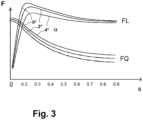
- the longitudinal tire force FL transmitted by a vehicle wheel 2 in the longitudinal direction of the vehicle and the transverse tire force FQ transmitted in the transverse direction of the tire 2 depend on the respective wheel slip s, as well as, for example.
- the wheel slip s depends in particular on the coefficient of friction ⁇ of the road or the surface.
- Figure 3 shows a corresponding model, according to which the two forces FL and FQ are shown as a function of the wheel slip s and the curves vary with the slip angle ⁇ .
- the wheel slip s can be defined as the ratio of the wheel speed, i.e. H.
- Wheel circumferential speed v2 can be determined compared to the vehicle speed v1, since with pure static friction without wheel slip, the wheel speed (wheel circumferential speed) v2 corresponds to the vehicle speed v1 when driving straight ahead.
- the above-mentioned considerations should generally be applied to both a braking process and an acceleration process, whereby the braked wheels may lock during the braking process and the wheels may spin during the driving process.
- the aim is to drive the vehicle wheel 2 via the drive device, i.e. H.
- the wheel hub motor 3 is adjusted in a range in which both a tire longitudinal force FL and a sufficient tire transverse force FQ can be exerted in order to achieve suitable cornering or lateral guidance of the vehicle 1.
- the drive control device 6 While driving, the drive control device 6 checks the wheel slip s of the individual vehicle wheels 2 based on the respective wheel speed signals n as well as a reference speed v1-ref of the vehicle 1 or a reference speed of the vehicle wheel v2ref, which can basically be calculated from modeling, as in Anti-lock braking systems (ABS) are common.
- ABS Anti-lock braking systems
- the exact value of the slip setpoint s-setpoint can be determined according to Figure 3 can be selected depending on the driving situation; In particular, the required tire lateral force FQ can be taken into account. This ensures a maximum or high transmission of the z. B.
- the drive control device 6 can also provide information about cornering, e.g. B. use a yaw rate ⁇ or a transverse acceleration aq, which may be determined directly by a corresponding sensor. Furthermore The respective slip angle ⁇ can be taken into account accordingly, so that a selection criterion k2 is formed for the target slip s-target.
- the speed of the tire slip s is controlled to the target slip s-soll, in that the wheel hub motor is controlled to accelerate or brake the vehicle wheel 2.
- the controlled actual drive torque M2 is currently determined.
- FIG. 2 can he in Figure 1
- the structure shown can also be done accordingly by means of the drive control device 6 and the central brake control device 10, which control the respective wheel brakes 9, e.g. B. pneumatic wheel brakes for braking individual vehicle wheels 2, controlled directly or, in the case of EBS, in particular indirectly via brake control signals S3.
- An electro-pneumatic valve device e.g. B. with relay valves and ABS valves, can be used so that the respective wheel brakes 9 subsequently transmit braking forces FB to the individual vehicle wheels 2.
- the wheel speed sensors 4 output the wheel speed signals n in the usual manner to the brake control device 10, which is in data connection with the central drive control device 6 or is integrated with it.
- the brake control device 10 can therefore also be integrated into the control if, for example. B. a stronger braking of the vehicle wheels 2 by means of the wheel brakes 9 designed as friction brakes is required. Otherwise, the regulation according to the invention advantageously takes place solely by controlling the drive device, ie here the wheel hub motors 3.
- step St0 the setting or regulation of an actual drive torque M2 on the respective vehicle wheel 2 takes place in step St1 by means of recuperation.
- step St2 it is further provided in step St2 to determine the wheel speeds n, the wheel slip s and a reference speed v2ref, as well as to determine or retrieve the target slip s-soll.
- step St3 it is continuously checked whether the instability criterion K1 is met. If there is a corresponding instability, the speed control is carried out according to branch y1 in step St4 in order to adjust the wheel slip s to the target slip s-set.
- step St4 it is continuously checked whether the transmitted actual drive torque M2 or the transmitted forces meet an end criterion K3 for terminating the slip control method.
- the wheel slip can no longer be evaluated according to the criterion k1, since this is currently being adjusted as a controlled variable to the target slip value s-set.
- the final criterion k3 is therefore evaluated using the transmitted actual drive torque M2.
- the final criterion k3 is advantageously dependent on the lower-level drive torque regulation or control in order to evaluate whether a stable situation exists and the higher-level slip control does not cause any relevant changes.
- the wheel slip s in the slip control in step St4, can be increased by the target value in a step St4a, i.e. H.
- the slip setpoint s-set can be varied in incremental steps.
- the torque control underlying the speed control of the wheel hub motor 3 can measure the resulting change in torque of the wheel hub motor 3 in step St4b.
- the drive control can be combined with an ABS control.
- the electrical braking or recuperation can be overlaid with an underlying friction braking with constant torque.
- friction braking via the wheel brake 9 can be regulated by means of an ABS control method via the central brake control device 10 (ABS control device) with simultaneous action of the wheel hub motor 3, in particular for recuperation.
- an optimal slip speed can be determined via a constant portion of the sliding speed.
- the target slip s-target can be specified by a driving dynamics system. In this way, the target slip s-set can be modified depending on the lateral force requirement and then limited more strongly if corresponding cornering forces are required. These can be taken from an ESC vehicle movement model.
- the speed of the wheel hub motor 3, ie, for example, the encoder signal, can be used instead of the wheel speed sensors 4 shown. If the electric drive 3 is input to the vehicle wheel 2 via a transmission, the respective transmission configuration is used to calculate the wheel speed n.
Landscapes
- Engineering & Computer Science (AREA)
- Transportation (AREA)
- Mechanical Engineering (AREA)
- Chemical & Material Sciences (AREA)
- Combustion & Propulsion (AREA)
- Automation & Control Theory (AREA)
- Life Sciences & Earth Sciences (AREA)
- Sustainable Development (AREA)
- Sustainable Energy (AREA)
- Power Engineering (AREA)
- Physics & Mathematics (AREA)
- Fluid Mechanics (AREA)
- Microelectronics & Electronic Packaging (AREA)
- Electric Propulsion And Braking For Vehicles (AREA)
- Regulating Braking Force (AREA)
Claims (22)
- Procédé permettant la régulation du patinage d'une roue de véhicule (2) entraînée par l'intermédiaire d'un entraînement électrique (3), comportant au moins les étapes suivantes :- commande de l'entraînement électrique (3) de la roue de véhicule (2) avec un couple d'entraînement réel (M2) dans une commande de couple (TC) dans une étape de commande de couple (St1),- détermination d'une vitesse de rotation de roue (n) et d'un patinage de roue (s) de la roue de véhicule (2) et caractérisé en ce que le procédé permettant la régulation du patinage comprend en outre les étapes supplémentaires suivantes :
évaluation du patinage de roue (s) par un critère d'instabilité (K1) pour savoir si une instabilité est présente (St3),- lors de la détection d'une instabilité, transition directe ou indirecte dans une régulation du patinage (SLC) du patinage de roue (s) sur un patinage de consigne (s-soll) par commande de l'entraînement électrique (3) (St4, étape de régulation du patinage superposée),- détermination du fait de savoir si un critère final (K3) permettant d'arrêter la régulation du patinage est satisfait (St5),- si le critère final (K3) est satisfait, retour à la commande de couple (TC) dans l'étape de commande de couple (St1). - Procédé selon la revendication 1, caractérisé en ce que- avant l'étape de commande de couple (St1), une étape de détermination de couple d'entraînement de consigne (St0-1) est prévue, dans laquelle un couple d'entraînement de consigne (M-soll) est déterminé, en particulier en fonction d'une entrée de conducteur, et- dans l'étape de commande de couple (St1), lors de la commande de l'entraînement électrique (3) de la roue de véhicule (2), le couple d'entraînement réel (M2) exercé est mesuré et réglé et/ou régulé sur le couple d'entraînement de consigne (M-soll).
- Procédé selon la revendication 1 ou 2, caractérisé en ce que la commande de couple (TC) est prévue en tant que régulation de couple d'entraînement secondaire pour l'accélération et/ou le freinage de la roue de véhicule (2), par exemple à une vitesse de consigne (v2-soll).
- Procédé selon l'une des revendications précédentes,
caractérisé en ce que, pendant la régulation du patinage (SLC), un freinage d'une roue de véhicule (2) par l'entraînement électrique (3) avec récupération est prévu au moins temporairement. - Procédé selon l'une des revendications précédentes,
caractérisé en ce que le couple d'entraînement réel (M2) exercé par l'entraînement électrique (3) sur la roue de véhicule (2) est déterminé par mesure d'un courant moteur (I3) introduit dans l'entraînement électrique (3). - Procédé selon l'une des revendications précédentes,
caractérisé en ce qu'un moteur de moyeu de roue (3), lequel accélère la roue de véhicule (2) et/ou freine la roue de véhicule (2) avec récupération, est prévu comme entraînement électrique (3). - Procédé selon l'une des revendications précédentes,
caractérisé en ce que plusieurs roues de véhicule (2) sont régulées en termes de patinage respectivement par l'intermédiaire d'un entraînement électrique (3), dans lequel les entraînements électriques (3) sont commandés par l'intermédiaire d'un appareil de commande d'entraînement central (6) qui envoie des signaux de commande d'entraînement (S1) permettant le réglage de couples d'entraînement de consigne (M2-soll) et reçoit des signaux d'information de couple moteur (S2) par l'intermédiaire des couples d'entraînement réels (M2) réglés sur les roues de véhicule (2). - Procédé selon l'une des revendications précédentes,
caractérisé en ce que le patinage de roue (s) de la roue de véhicule (2) est déterminé à partir d'une part de la vitesse de rotation de roue (n) déterminée ou d'une vitesse de rotation d'entraînement (n3) du moteur de moyeu de roue (3) et
d'autre part d'une vitesse de référence de roue (v2ref) ou d'une vitesse de référence de véhicule (v1-ref). - Procédé selon l'une des revendications précédentes,
caractérisé en ce que le patinage de consigne (s-soll) est sélectionné sur la base d'un modèle de patinage de force (Fig. 3) en tenant compte de forces transversales (FQ) de roue à transmettre. - Procédé selon l'une des revendications précédentes,
caractérisé en ce que le patinage de consigne (s-soll) de la régulation du patinage est déterminé sur la base d'un critère de sélection (K2), en particulier en utilisant des forces transversales (FQ) actuelles ou prévues de la roue de véhicule (2) et/ou un angle de dérive (α). - Procédé selon l'une des revendications précédentes,
caractérisé en ce que le patinage de consigne (s-soll) est déterminé et prédéfini par une régulation de la dynamique de conduite (VLC). - Procédé selon l'une des revendications précédentes,
caractérisé en ce que, pour le critère d'instabilité (k1), le patinage de roue (s) de la roue de véhicule (2) est comparé avec au moins un patinage limite (s-thr) et, en cas de dépassement du patinage limite (s-thr), une instabilité est détectée. - Procédé selon la revendication 12, caractérisé en ce que le patinage limite (s-thr) est inférieur au patinage de consigne (s-soll), par exemple avec le patinage limite (s-thr) égal à 7 pour cent et le patinage de consigne (s-soll) égal à 15 pour cent.
- Procédé selon la revendication 12 ou 13, caractérisé en ce que, lors de la détection d'une instabilité,tout d'abord, en cas de dépassement d'un patinage limite inférieur (s-thr-lo) du patinage de roue (s), une transition vers une régulation de vitesse de rotation (nLC) de la roue de véhicule (2) est effectuée eten cas de dépassement d'un patinage limite supérieur (s-thr-lo), une transition vers la régulation du patinage (SLC) de la roue de véhicule (2) est effectuée, lors de laquelle le patinage de roue (s) est régulé sur le patinage de consigne (s-soll) (St4, étape de régulation du patinage superposée).
- Procédé selon l'une des revendications précédentes,
caractérisé en ce que le couple d'entraînement réel (M2) transmis pendant la régulation du patinage (SLC) est évalué comme critère final (K3). - Procédé selon la revendication 15 caractérisé en ce que le couple d'entraînement réel (M2) est comparé avec le couple d'entraînement de consigne (M-soll) prédéfini dans la commande de couple de rotation secondaire (St1) (M2 < M-soll),
dans lequel, dans le cas où le couple d'entraînement réel (M2) transmis est inférieur au couple d'entraînement de consigne (M-soll) prédéfini dans la commande de couple (TC) secondaire, le critère final (k3) est satisfait (St5). - Procédé selon l'une des revendications précédentes,
caractérisé en ce que, lors de la régulation du patinage (St4), une adaptation du patinage de consigne (s-soll) est effectuée par le fait que- après le réglage initial du patinage de consigne (s-soll), un patinage de consigne actuel (s-soll-ink) est ensuite spécifié par une déviation par étapes incrémentielles (Δs) et- la variation résultante du couple d'entraînement (M2) transmis par l'entraînement électrique (3) est déterminée,- dans lequel, lors d'une constatation d'une augmentation du couple d'entraînement (M2) transmis, le patinage de consigne actuel (s-soll-ink) est spécifié comme nouveau patinage de consigne (s-soll). - Procédé selon la revendication 17, caractérisé en ce que l'adaptation du patinage de consigne (s-soll) est arrêtée ou limitée en fonction d'un autre critère final d'adaptation (k5), par exemple lorsqu'une limite de patinage supérieure (s-up), par exemple 22 pour cent, est atteinte.
- Procédé selon l'une des revendications précédentes,
caractérisé en ce qu'une utilisation de freins de roue, en particulier de freins à friction (9), est en outre prévue simultanément. - Procédé selon l'une des revendications précédentes,
caractérisé en ce que des signaux de vitesse de rotation de roue (n) sont déterminés par des capteurs de vitesse de rotation de roue (4) et/ou la détermination d'une vitesse de rotation de moteur (n3) de la machine électrique, par exemple du moteur de nombre de roues (3). - Dispositif (12) permettant la régulation du patinage d'une roue de véhicule (2), lequel présente :un entraînement électrique (3) permettant de transmettre des couples d'entraînement réels (M2) qui accélèrent et qui freinent à la roue de véhicule (2),un appareil de commande (3a) prévu en tant que partie de l'entraînement électrique (3) ou en supplément et permettant d'alimenter l'entraînement électrique (3),un appareil de commande d'entraînement central (6) permettant de commander l'appareil de commande (3a) par l'intermédiaire de signaux de commande d'entraînement (S1) et permettant de recevoir des signaux d'information de couple moteur (S2) par l'intermédiaire du couple d'entraînement réel (M2) commandé actuellement par l'appareil de commande (3a),caractérisé en ce quel'appareil de commande d'entraînement central (6) est adapté ou configuré pour mettre en oeuvre un procédé selon l'une des revendications précédentes.
- Véhicule comportant un dispositif (12) selon la revendication 21 et au moins une roue de véhicule (2) commandée par le dispositif (12).
Applications Claiming Priority (2)
| Application Number | Priority Date | Filing Date | Title |
|---|---|---|---|
| DE102019135087.5A DE102019135087A1 (de) | 2019-12-19 | 2019-12-19 | Verfahren und Vorrichtung zur Schlupfregelung eines Fahrzeugrades |
| PCT/EP2020/084047 WO2021121951A1 (fr) | 2019-12-19 | 2020-12-01 | Procédé et dispositif de contrôle de boucle de glissement d'une roue de véhicule |
Publications (2)
| Publication Number | Publication Date |
|---|---|
| EP4077077A1 EP4077077A1 (fr) | 2022-10-26 |
| EP4077077B1 true EP4077077B1 (fr) | 2023-12-27 |
Family
ID=73695002
Family Applications (1)
| Application Number | Title | Priority Date | Filing Date |
|---|---|---|---|
| EP20817278.3A Active EP4077077B1 (fr) | 2019-12-19 | 2020-12-01 | Méthode et système de régulation du glissement relatif d'une roue de véhicule |
Country Status (5)
| Country | Link |
|---|---|
| US (1) | US12145591B2 (fr) |
| EP (1) | EP4077077B1 (fr) |
| CN (1) | CN114787007B (fr) |
| DE (1) | DE102019135087A1 (fr) |
| WO (1) | WO2021121951A1 (fr) |
Families Citing this family (16)
| Publication number | Priority date | Publication date | Assignee | Title |
|---|---|---|---|---|
| EP4480769A3 (fr) * | 2020-11-16 | 2025-03-19 | Volvo Truck Corporation | Procédé de commande de patinage de roue d'un véhicule |
| EP4005883B1 (fr) * | 2020-11-25 | 2025-11-26 | Volvo Truck Corporation | Système et procédé de réglage de glissement de roue d'un véhicule |
| EP4122782B1 (fr) | 2021-07-22 | 2024-09-04 | Volvo Truck Corporation | Procédé de commande de freinage et/ou de la traction d'un véhicule |
| EP4631805A3 (fr) * | 2022-05-05 | 2026-01-21 | Ipgate Ag | Système de dynamique de conduite, véhicule ainsi que procédé de fonctionnement d'un système de dynamique de conduite |
| DE102022123507A1 (de) | 2022-09-14 | 2024-03-14 | Zf Cv Systems Global Gmbh | Verfahren zum Regeln für ein Fahrzeug, Computerprogramm und/oder computerlesbares Medium, Steuergerät und Fahrzeug, insbesondere Nutzfahrzeug |
| DE102022123479A1 (de) | 2022-09-14 | 2024-03-14 | Zf Cv Systems Global Gmbh | Verfahren zum Betreiben einer Reibbremsvorrichtung, Computerprogramm und/oder computerlesbares Medium, Steuergerät, Reibbremsvorrichtung und Fahrzeug, insbesondere Nutzfahrzeug |
| DE102022123478A1 (de) | 2022-09-14 | 2024-03-14 | Zf Cv Systems Global Gmbh | Verfahren zum Regeln eines Generatorbremsmoments eines elektrischen Antriebs für ein Fahrzeug, insbesondere Nutzfahrzeug, Computerprogramm und/oder computerlesbares Medium, Steuergerät, elektrischer Antrieb oder elektrisches Bremssystem und Fahrzeug, insbesondere Nutzfahrzeug |
| DE102022124553A1 (de) | 2022-09-23 | 2024-03-28 | Bayerische Motoren Werke Aktiengesellschaft | Verfahren zum Betreiben eines Fahrzeugs und Fahrzeug |
| DE102023102657A1 (de) * | 2023-02-03 | 2024-08-08 | Zf Cv Systems Global Gmbh | Verfahren zum Steuern eines Fahrzeuges, Antriebs-Steuereinheit und Fahrzeug |
| DE102023122142B4 (de) | 2023-08-18 | 2025-10-16 | Dr. Ing. H.C. F. Porsche Aktiengesellschaft | Verfahren zur Erkennung von Schlupf bei den Rädern eines Kraftfahrzeuges sowie entsprechendes Kraftfahrzeug |
| DE102023124792A1 (de) * | 2023-09-14 | 2025-03-20 | Dr. Ing. H.C. F. Porsche Aktiengesellschaft | Kraftfahrzeug zur Schleppmoment-Kompensation einer PSM im Fehlerfall |
| DE102023210225A1 (de) * | 2023-10-18 | 2025-04-24 | Robert Bosch Gesellschaft mit beschränkter Haftung | Verfahren zum Betreiben eines Elektrofahrzeugs und Steuereinrichtung für ein Elektrofahrzeug |
| DE102024201862A1 (de) * | 2024-02-29 | 2025-09-04 | Robert Bosch Gesellschaft mit beschränkter Haftung | Verfahren zum Betreiben eines Kraftfahrzeugs, Computerprogrammprodukt, Speichermedium, Computereinrichtung |
| DE102024201863A1 (de) * | 2024-02-29 | 2025-09-04 | Robert Bosch Gesellschaft mit beschränkter Haftung | Verfahren zum Betreiben eines Kraftfahrzeugs, Computerprogrammprodukt, Speichermedium, Computereinrichtung |
| DE102024201861A1 (de) * | 2024-02-29 | 2025-09-04 | Robert Bosch Gesellschaft mit beschränkter Haftung | Verfahren zum Betreiben eines Kraftfahrzeugs, Computerprogrammprodukt, Speichermedium, Computereinrichtung |
| FR3164676A1 (fr) * | 2024-07-19 | 2026-01-23 | Stellantis Auto Sas | Procede de reduction de couple d’une machine electrique en cas de manque d’adherence au sol d’un vehicule |
Family Cites Families (20)
| Publication number | Priority date | Publication date | Assignee | Title |
|---|---|---|---|---|
| US6909959B2 (en) | 2003-03-07 | 2005-06-21 | Stephen James Hallowell | Torque distribution systems and methods for wheeled vehicles |
| JP4186081B2 (ja) | 2005-02-02 | 2008-11-26 | トヨタ自動車株式会社 | 車輌の制駆動力制御装置 |
| FR2904271B1 (fr) * | 2006-07-28 | 2008-09-26 | Renault Sas | Procede et dispositif de controle du glissement d'une roue pour vehicule automobile |
| DE102008001879A1 (de) * | 2008-05-20 | 2009-11-26 | Zf Friedrichshafen Ag | Verfahren und Einrichtung zur Schlupfregelung bei einem Schlepperfahrzeug oder dergleichen |
| DE102010003076A1 (de) | 2009-08-05 | 2011-08-18 | Continental Automotive GmbH, 30165 | Verfahren zur Regelung eines Radbremsschlupfes und Radbremsschlupfregelsystem für ein Fahrzeug mit einem Elektroantrieb |
| US9020699B2 (en) | 2009-12-15 | 2015-04-28 | Continental Teves Ag & Co. Ohg | Method and braking system for influencing driving dynamics by means of braking and driving operations |
| DE102010028071A1 (de) * | 2010-04-22 | 2011-10-27 | Zf Friedrichshafen Ag | Verfahren zur Fahrsteuerung eines Kraftfahrzeugs |
| EP2612796B1 (fr) | 2010-08-30 | 2016-05-04 | Toyota Jidosha Kabushiki Kaisha | Dispositif de commande de force de freinage pour véhicule |
| DE102011100814A1 (de) | 2011-05-06 | 2012-11-08 | Audi Ag | Einrichtung zur Antriebsschlupfregelung für ein Fahrzeug mit elektromotorischem Fahrzeugantrieb |
| ITTO20120001A1 (it) | 2012-01-04 | 2013-07-05 | Mino S P A | Laminatoio multicilindro, in particolare di tipo sesto |
| US10640113B2 (en) * | 2013-08-20 | 2020-05-05 | Ge Global Sourcing Llc | System and method for controlling a vehicle |
| JP2015100149A (ja) | 2013-11-18 | 2015-05-28 | Ntn株式会社 | アンチロックブレーキ制御装置 |
| DE102013226894A1 (de) * | 2013-12-20 | 2015-06-25 | Bayerische Motoren Werke Aktiengesellschaft | Verfahren zur Vermeidung von Schwingungen im Antriebsstrang eines Kraftfahrzeugs mit Elektroantrieb |
| CN104002699A (zh) * | 2014-05-26 | 2014-08-27 | 北京理工大学 | 一种分布式驱动电动汽车的控制方法 |
| DE102014210537A1 (de) | 2014-06-04 | 2015-12-17 | Robert Bosch Gmbh | Verfahren zum Betreiben eines Hybridfahrzeugs |
| CN104828044A (zh) * | 2014-07-03 | 2015-08-12 | 北汽福田汽车股份有限公司 | 车辆的制动控制方法及系统 |
| DE102014109790A1 (de) * | 2014-07-11 | 2016-01-14 | Linde Material Handling Gmbh | Verfahren zur Antriebsschlupfregelung bei einem Zweiwegefahrzeug |
| CN106427662A (zh) * | 2016-06-30 | 2017-02-22 | 创驱(上海)新能源科技有限公司 | 一种新能源汽车防抱死控制方法 |
| JP6859624B2 (ja) | 2016-07-28 | 2021-04-14 | 日産自動車株式会社 | 燃料電池システム及びその制御方法 |
| DE102017211436A1 (de) * | 2017-07-05 | 2019-01-10 | Robert Bosch Gmbh | Verfahren und Vorrichtung zum Ansteuern eines Elektromotors für ein Fahrzeug |
-
2019
- 2019-12-19 DE DE102019135087.5A patent/DE102019135087A1/de active Pending
-
2020
- 2020-12-01 EP EP20817278.3A patent/EP4077077B1/fr active Active
- 2020-12-01 CN CN202080084938.XA patent/CN114787007B/zh active Active
- 2020-12-01 WO PCT/EP2020/084047 patent/WO2021121951A1/fr not_active Ceased
-
2022
- 2022-06-17 US US17/843,766 patent/US12145591B2/en active Active
Also Published As
| Publication number | Publication date |
|---|---|
| US20220315004A1 (en) | 2022-10-06 |
| EP4077077A1 (fr) | 2022-10-26 |
| DE102019135087A1 (de) | 2021-06-24 |
| CN114787007B (zh) | 2025-06-03 |
| CN114787007A (zh) | 2022-07-22 |
| US12145591B2 (en) | 2024-11-19 |
| WO2021121951A1 (fr) | 2021-06-24 |
Similar Documents
| Publication | Publication Date | Title |
|---|---|---|
| EP4077077B1 (fr) | Méthode et système de régulation du glissement relatif d'une roue de véhicule | |
| EP2760714B1 (fr) | Système de freinage à régulation de glissement, destiné à des véhicules électriques | |
| EP3374224B1 (fr) | Système de régulation de la dynamique de conduite dans un véhicule automobile et unité de commande électronique de la dynamique de conduite pour un système de régulation de la dynamique de conduite | |
| WO2008037347A1 (fr) | Système de freinage et méthode de freinage d'un véhicule à propulsion hybride | |
| EP3544849B1 (fr) | Système de transmission intégrale pour un véhicule automobile électrique et procédé permettant de faire fonctionner un système de transmission intégrale d'un tel véhicule | |
| WO2022111951A1 (fr) | Procédé de commande d'un ensemble de freinage d'un véhicule automobile | |
| EP0985586B1 (fr) | Système d'antiblocage pour un système de freinage électromécanique de véhicule basé sur un régulateur de logique floue | |
| DE102009039614A1 (de) | Verfahren zur Steuerung eines rekuperativen Verzögerungssystems für ein Kraftfahrzeug | |
| EP3517377B1 (fr) | Procédé de fonctionnement d'un véhicule automobile ainsi que véhicule automobile | |
| WO2013186026A2 (fr) | Procédé pour augmenter le taux de récupération | |
| EP2440439B1 (fr) | Procédé de production d'un couple différentiel agissant sur les roues d'un véhicule | |
| EP3793871B1 (fr) | Système pour véhicule à propulsion électrique, véhicule équipé de ce système | |
| DE102020121635A1 (de) | Verfahren zum Betreiben eines Bremssystems eines Fahrzeuges | |
| DE19949220B4 (de) | Verfahren und Vorrichtung zur Steuerung der Antriebseinheit eines Fahrzeugs | |
| DE102010027978A1 (de) | Fahrerassistenzsystem und Verfahren zur Einstellung eines Fahrerassistenzsystems | |
| EP4240625B1 (fr) | Contrôle efficace du patinage des roues d'un véhicule utilitaire à propulsion électrique | |
| EP4587289A1 (fr) | Procédé de commande d'un couple de freinage de générateur d'un entraînement électrique d'un véhicule, en particulier d'un véhicule utilitaire, programme informatique et/ou support lisible par ordinateur, dispositif de commande, entraînement électrique ou système de freinage électrique et véhicule, en particulier véhicule utilitaire | |
| DE102009014824A1 (de) | Verfahren zum Betreiben eines Hybridantriebs eines Kraftfahrzeugs sowie Kraftfahrzeug mit einem Hybridantrieb | |
| EP3717325B1 (fr) | Procédé et système de dynamique de conduite servant à réguler une opération de démarrage d'un véhicule | |
| EP4416020B1 (fr) | Procédé pour faire fonctionner un système de régulation du freinage, système de régulation du freinage, programme informatique et support d'enregistrement lisible par ordinateur | |
| DE102024120292A1 (de) | Bremsverfahren, elektronisches Bremssystem und Fahrzeug | |
| DE102018111679A1 (de) | System mit einem Steuergerät für ein Nutzfahrzeug sowie ein Verfahren zum Betreiben eines Nutzfahrzeugs mit dem System | |
| DE102022123978A1 (de) | Verfahren zum Betreiben eines zumindest teilweise elektrisch angetriebenen Fahrzeugs und Fahrzeug | |
| WO2024120889A1 (fr) | Procédé de fonctionnement, basé sur un couple, d'un onduleur d'un entraînement électrique d'un véhicule, en particulier d'un véhicule utilitaire, onduleur, entraînement électrique, véhicule, en particulier véhicule utilitaire, programme informatique et/ou support lisible par ordinateur | |
| DE102023123211A1 (de) | Verfahren zum Betrieb eines hybriden Antriebsstrangs |
Legal Events
| Date | Code | Title | Description |
|---|---|---|---|
| STAA | Information on the status of an ep patent application or granted ep patent |
Free format text: STATUS: UNKNOWN |
|
| STAA | Information on the status of an ep patent application or granted ep patent |
Free format text: STATUS: THE INTERNATIONAL PUBLICATION HAS BEEN MADE |
|
| PUAI | Public reference made under article 153(3) epc to a published international application that has entered the european phase |
Free format text: ORIGINAL CODE: 0009012 |
|
| STAA | Information on the status of an ep patent application or granted ep patent |
Free format text: STATUS: REQUEST FOR EXAMINATION WAS MADE |
|
| 17P | Request for examination filed |
Effective date: 20220719 |
|
| AK | Designated contracting states |
Kind code of ref document: A1 Designated state(s): AL AT BE BG CH CY CZ DE DK EE ES FI FR GB GR HR HU IE IS IT LI LT LU LV MC MK MT NL NO PL PT RO RS SE SI SK SM TR |
|
| DAV | Request for validation of the european patent (deleted) | ||
| DAX | Request for extension of the european patent (deleted) | ||
| GRAP | Despatch of communication of intention to grant a patent |
Free format text: ORIGINAL CODE: EPIDOSNIGR1 |
|
| STAA | Information on the status of an ep patent application or granted ep patent |
Free format text: STATUS: GRANT OF PATENT IS INTENDED |
|
| INTG | Intention to grant announced |
Effective date: 20231013 |
|
| GRAS | Grant fee paid |
Free format text: ORIGINAL CODE: EPIDOSNIGR3 |
|
| GRAA | (expected) grant |
Free format text: ORIGINAL CODE: 0009210 |
|
| STAA | Information on the status of an ep patent application or granted ep patent |
Free format text: STATUS: THE PATENT HAS BEEN GRANTED |
|
| AK | Designated contracting states |
Kind code of ref document: B1 Designated state(s): AL AT BE BG CH CY CZ DE DK EE ES FI FR GB GR HR HU IE IS IT LI LT LU LV MC MK MT NL NO PL PT RO RS SE SI SK SM TR |
|
| REG | Reference to a national code |
Ref country code: GB Ref legal event code: FG4D Free format text: NOT ENGLISH |
|
| REG | Reference to a national code |
Ref country code: CH Ref legal event code: EP |
|
| REG | Reference to a national code |
Ref country code: DE Ref legal event code: R096 Ref document number: 502020006560 Country of ref document: DE |
|
| REG | Reference to a national code |
Ref country code: IE Ref legal event code: FG4D Free format text: LANGUAGE OF EP DOCUMENT: GERMAN |
|
| PG25 | Lapsed in a contracting state [announced via postgrant information from national office to epo] |
Ref country code: GR Free format text: LAPSE BECAUSE OF FAILURE TO SUBMIT A TRANSLATION OF THE DESCRIPTION OR TO PAY THE FEE WITHIN THE PRESCRIBED TIME-LIMIT Effective date: 20240328 |
|
| REG | Reference to a national code |
Ref country code: LT Ref legal event code: MG9D |
|
| PG25 | Lapsed in a contracting state [announced via postgrant information from national office to epo] |
Ref country code: LT Free format text: LAPSE BECAUSE OF FAILURE TO SUBMIT A TRANSLATION OF THE DESCRIPTION OR TO PAY THE FEE WITHIN THE PRESCRIBED TIME-LIMIT Effective date: 20231227 |
|
| PG25 | Lapsed in a contracting state [announced via postgrant information from national office to epo] |
Ref country code: ES Free format text: LAPSE BECAUSE OF FAILURE TO SUBMIT A TRANSLATION OF THE DESCRIPTION OR TO PAY THE FEE WITHIN THE PRESCRIBED TIME-LIMIT Effective date: 20231227 |
|
| PG25 | Lapsed in a contracting state [announced via postgrant information from national office to epo] |
Ref country code: LT Free format text: LAPSE BECAUSE OF FAILURE TO SUBMIT A TRANSLATION OF THE DESCRIPTION OR TO PAY THE FEE WITHIN THE PRESCRIBED TIME-LIMIT Effective date: 20231227 Ref country code: GR Free format text: LAPSE BECAUSE OF FAILURE TO SUBMIT A TRANSLATION OF THE DESCRIPTION OR TO PAY THE FEE WITHIN THE PRESCRIBED TIME-LIMIT Effective date: 20240328 Ref country code: FI Free format text: LAPSE BECAUSE OF FAILURE TO SUBMIT A TRANSLATION OF THE DESCRIPTION OR TO PAY THE FEE WITHIN THE PRESCRIBED TIME-LIMIT Effective date: 20231227 Ref country code: ES Free format text: LAPSE BECAUSE OF FAILURE TO SUBMIT A TRANSLATION OF THE DESCRIPTION OR TO PAY THE FEE WITHIN THE PRESCRIBED TIME-LIMIT Effective date: 20231227 Ref country code: BG Free format text: LAPSE BECAUSE OF FAILURE TO SUBMIT A TRANSLATION OF THE DESCRIPTION OR TO PAY THE FEE WITHIN THE PRESCRIBED TIME-LIMIT Effective date: 20240327 |
|
| REG | Reference to a national code |
Ref country code: NL Ref legal event code: MP Effective date: 20231227 |
|
| PG25 | Lapsed in a contracting state [announced via postgrant information from national office to epo] |
Ref country code: NL Free format text: LAPSE BECAUSE OF FAILURE TO SUBMIT A TRANSLATION OF THE DESCRIPTION OR TO PAY THE FEE WITHIN THE PRESCRIBED TIME-LIMIT Effective date: 20231227 |
|
| PG25 | Lapsed in a contracting state [announced via postgrant information from national office to epo] |
Ref country code: SE Free format text: LAPSE BECAUSE OF FAILURE TO SUBMIT A TRANSLATION OF THE DESCRIPTION OR TO PAY THE FEE WITHIN THE PRESCRIBED TIME-LIMIT Effective date: 20231227 Ref country code: RS Free format text: LAPSE BECAUSE OF FAILURE TO SUBMIT A TRANSLATION OF THE DESCRIPTION OR TO PAY THE FEE WITHIN THE PRESCRIBED TIME-LIMIT Effective date: 20231227 Ref country code: NO Free format text: LAPSE BECAUSE OF FAILURE TO SUBMIT A TRANSLATION OF THE DESCRIPTION OR TO PAY THE FEE WITHIN THE PRESCRIBED TIME-LIMIT Effective date: 20240327 Ref country code: NL Free format text: LAPSE BECAUSE OF FAILURE TO SUBMIT A TRANSLATION OF THE DESCRIPTION OR TO PAY THE FEE WITHIN THE PRESCRIBED TIME-LIMIT Effective date: 20231227 Ref country code: LV Free format text: LAPSE BECAUSE OF FAILURE TO SUBMIT A TRANSLATION OF THE DESCRIPTION OR TO PAY THE FEE WITHIN THE PRESCRIBED TIME-LIMIT Effective date: 20231227 Ref country code: HR Free format text: LAPSE BECAUSE OF FAILURE TO SUBMIT A TRANSLATION OF THE DESCRIPTION OR TO PAY THE FEE WITHIN THE PRESCRIBED TIME-LIMIT Effective date: 20231227 |
|
| PG25 | Lapsed in a contracting state [announced via postgrant information from national office to epo] |
Ref country code: IS Free format text: LAPSE BECAUSE OF FAILURE TO SUBMIT A TRANSLATION OF THE DESCRIPTION OR TO PAY THE FEE WITHIN THE PRESCRIBED TIME-LIMIT Effective date: 20240427 |
|
| PG25 | Lapsed in a contracting state [announced via postgrant information from national office to epo] |
Ref country code: CZ Free format text: LAPSE BECAUSE OF FAILURE TO SUBMIT A TRANSLATION OF THE DESCRIPTION OR TO PAY THE FEE WITHIN THE PRESCRIBED TIME-LIMIT Effective date: 20231227 |
|
| PG25 | Lapsed in a contracting state [announced via postgrant information from national office to epo] |
Ref country code: SK Free format text: LAPSE BECAUSE OF FAILURE TO SUBMIT A TRANSLATION OF THE DESCRIPTION OR TO PAY THE FEE WITHIN THE PRESCRIBED TIME-LIMIT Effective date: 20231227 |
|
| PG25 | Lapsed in a contracting state [announced via postgrant information from national office to epo] |
Ref country code: SM Free format text: LAPSE BECAUSE OF FAILURE TO SUBMIT A TRANSLATION OF THE DESCRIPTION OR TO PAY THE FEE WITHIN THE PRESCRIBED TIME-LIMIT Effective date: 20231227 Ref country code: SK Free format text: LAPSE BECAUSE OF FAILURE TO SUBMIT A TRANSLATION OF THE DESCRIPTION OR TO PAY THE FEE WITHIN THE PRESCRIBED TIME-LIMIT Effective date: 20231227 Ref country code: RO Free format text: LAPSE BECAUSE OF FAILURE TO SUBMIT A TRANSLATION OF THE DESCRIPTION OR TO PAY THE FEE WITHIN THE PRESCRIBED TIME-LIMIT Effective date: 20231227 Ref country code: IT Free format text: LAPSE BECAUSE OF FAILURE TO SUBMIT A TRANSLATION OF THE DESCRIPTION OR TO PAY THE FEE WITHIN THE PRESCRIBED TIME-LIMIT Effective date: 20231227 Ref country code: IS Free format text: LAPSE BECAUSE OF FAILURE TO SUBMIT A TRANSLATION OF THE DESCRIPTION OR TO PAY THE FEE WITHIN THE PRESCRIBED TIME-LIMIT Effective date: 20240427 Ref country code: EE Free format text: LAPSE BECAUSE OF FAILURE TO SUBMIT A TRANSLATION OF THE DESCRIPTION OR TO PAY THE FEE WITHIN THE PRESCRIBED TIME-LIMIT Effective date: 20231227 Ref country code: CZ Free format text: LAPSE BECAUSE OF FAILURE TO SUBMIT A TRANSLATION OF THE DESCRIPTION OR TO PAY THE FEE WITHIN THE PRESCRIBED TIME-LIMIT Effective date: 20231227 |
|
| PG25 | Lapsed in a contracting state [announced via postgrant information from national office to epo] |
Ref country code: PL Free format text: LAPSE BECAUSE OF FAILURE TO SUBMIT A TRANSLATION OF THE DESCRIPTION OR TO PAY THE FEE WITHIN THE PRESCRIBED TIME-LIMIT Effective date: 20231227 Ref country code: PT Free format text: LAPSE BECAUSE OF FAILURE TO SUBMIT A TRANSLATION OF THE DESCRIPTION OR TO PAY THE FEE WITHIN THE PRESCRIBED TIME-LIMIT Effective date: 20240429 |
|
| PG25 | Lapsed in a contracting state [announced via postgrant information from national office to epo] |
Ref country code: PT Free format text: LAPSE BECAUSE OF FAILURE TO SUBMIT A TRANSLATION OF THE DESCRIPTION OR TO PAY THE FEE WITHIN THE PRESCRIBED TIME-LIMIT Effective date: 20240429 Ref country code: PL Free format text: LAPSE BECAUSE OF FAILURE TO SUBMIT A TRANSLATION OF THE DESCRIPTION OR TO PAY THE FEE WITHIN THE PRESCRIBED TIME-LIMIT Effective date: 20231227 |
|
| REG | Reference to a national code |
Ref country code: DE Ref legal event code: R097 Ref document number: 502020006560 Country of ref document: DE |
|
| PG25 | Lapsed in a contracting state [announced via postgrant information from national office to epo] |
Ref country code: DK Free format text: LAPSE BECAUSE OF FAILURE TO SUBMIT A TRANSLATION OF THE DESCRIPTION OR TO PAY THE FEE WITHIN THE PRESCRIBED TIME-LIMIT Effective date: 20231227 |
|
| PG25 | Lapsed in a contracting state [announced via postgrant information from national office to epo] |
Ref country code: DK Free format text: LAPSE BECAUSE OF FAILURE TO SUBMIT A TRANSLATION OF THE DESCRIPTION OR TO PAY THE FEE WITHIN THE PRESCRIBED TIME-LIMIT Effective date: 20231227 |
|
| PLBE | No opposition filed within time limit |
Free format text: ORIGINAL CODE: 0009261 |
|
| STAA | Information on the status of an ep patent application or granted ep patent |
Free format text: STATUS: NO OPPOSITION FILED WITHIN TIME LIMIT |
|
| 26N | No opposition filed |
Effective date: 20240930 |
|
| PGFP | Annual fee paid to national office [announced via postgrant information from national office to epo] |
Ref country code: GB Payment date: 20241001 Year of fee payment: 5 |
|
| PGFP | Annual fee paid to national office [announced via postgrant information from national office to epo] |
Ref country code: FR Payment date: 20241001 Year of fee payment: 5 |
|
| PG25 | Lapsed in a contracting state [announced via postgrant information from national office to epo] |
Ref country code: SI Free format text: LAPSE BECAUSE OF FAILURE TO SUBMIT A TRANSLATION OF THE DESCRIPTION OR TO PAY THE FEE WITHIN THE PRESCRIBED TIME-LIMIT Effective date: 20231227 |
|
| PG25 | Lapsed in a contracting state [announced via postgrant information from national office to epo] |
Ref country code: MC Free format text: LAPSE BECAUSE OF FAILURE TO SUBMIT A TRANSLATION OF THE DESCRIPTION OR TO PAY THE FEE WITHIN THE PRESCRIBED TIME-LIMIT Effective date: 20231227 |
|
| REG | Reference to a national code |
Ref country code: CH Ref legal event code: PL |
|
| PG25 | Lapsed in a contracting state [announced via postgrant information from national office to epo] |
Ref country code: LU Free format text: LAPSE BECAUSE OF NON-PAYMENT OF DUE FEES Effective date: 20241201 |
|
| REG | Reference to a national code |
Ref country code: BE Ref legal event code: MM Effective date: 20241231 |
|
| PG25 | Lapsed in a contracting state [announced via postgrant information from national office to epo] |
Ref country code: BE Free format text: LAPSE BECAUSE OF NON-PAYMENT OF DUE FEES Effective date: 20241231 |
|
| PG25 | Lapsed in a contracting state [announced via postgrant information from national office to epo] |
Ref country code: CH Free format text: LAPSE BECAUSE OF NON-PAYMENT OF DUE FEES Effective date: 20241231 |
|
| PG25 | Lapsed in a contracting state [announced via postgrant information from national office to epo] |
Ref country code: IE Free format text: LAPSE BECAUSE OF NON-PAYMENT OF DUE FEES Effective date: 20241201 |
|
| PGFP | Annual fee paid to national office [announced via postgrant information from national office to epo] |
Ref country code: DE Payment date: 20250930 Year of fee payment: 6 |
|
| PGFP | Annual fee paid to national office [announced via postgrant information from national office to epo] |
Ref country code: AT Payment date: 20260113 Year of fee payment: 5 |
|
| PG25 | Lapsed in a contracting state [announced via postgrant information from national office to epo] |
Ref country code: CY Free format text: LAPSE BECAUSE OF FAILURE TO SUBMIT A TRANSLATION OF THE DESCRIPTION OR TO PAY THE FEE WITHIN THE PRESCRIBED TIME-LIMIT; INVALID AB INITIO Effective date: 20201201 |