EP4077828B1 - Cloison sèche et procédé de construction d'une cloison sèche - Google Patents
Cloison sèche et procédé de construction d'une cloison sèche Download PDFInfo
- Publication number
- EP4077828B1 EP4077828B1 EP19835349.2A EP19835349A EP4077828B1 EP 4077828 B1 EP4077828 B1 EP 4077828B1 EP 19835349 A EP19835349 A EP 19835349A EP 4077828 B1 EP4077828 B1 EP 4077828B1
- Authority
- EP
- European Patent Office
- Prior art keywords
- crossbeam
- stud
- support structure
- drywall
- stud elements
- Prior art date
- Legal status (The legal status is an assumption and is not a legal conclusion. Google has not performed a legal analysis and makes no representation as to the accuracy of the status listed.)
- Active
Links
Images




Classifications
-
- E—FIXED CONSTRUCTIONS
- E04—BUILDING
- E04C—STRUCTURAL ELEMENTS; BUILDING MATERIALS
- E04C2/00—Building elements of relatively thin form for the construction of parts of buildings, e.g. sheet materials, slabs, or panels
- E04C2/30—Building elements of relatively thin form for the construction of parts of buildings, e.g. sheet materials, slabs, or panels characterised by the shape or structure
- E04C2/38—Building elements of relatively thin form for the construction of parts of buildings, e.g. sheet materials, slabs, or panels characterised by the shape or structure with attached ribs, flanges, or the like, e.g. framed panels
- E04C2/384—Building elements of relatively thin form for the construction of parts of buildings, e.g. sheet materials, slabs, or panels characterised by the shape or structure with attached ribs, flanges, or the like, e.g. framed panels with a metal frame
-
- E—FIXED CONSTRUCTIONS
- E04—BUILDING
- E04B—GENERAL BUILDING CONSTRUCTIONS; WALLS, e.g. PARTITIONS; ROOFS; FLOORS; CEILINGS; INSULATION OR OTHER PROTECTION OF BUILDINGS
- E04B2/00—Walls, e.g. partitions, for buildings; Wall construction with regard to insulation; Connections specially adapted to walls
- E04B2/74—Removable non-load-bearing partitions; Partitions with a free upper edge
- E04B2/7407—Removable non-load-bearing partitions; Partitions with a free upper edge assembled using frames with infill panels or coverings only; made-up of panels and a support structure incorporating posts
- E04B2/7453—Removable non-load-bearing partitions; Partitions with a free upper edge assembled using frames with infill panels or coverings only; made-up of panels and a support structure incorporating posts with panels and support posts, extending from floor to ceiling
- E04B2/7457—Removable non-load-bearing partitions; Partitions with a free upper edge assembled using frames with infill panels or coverings only; made-up of panels and a support structure incorporating posts with panels and support posts, extending from floor to ceiling with wallboards attached to the outer faces of the posts, parallel to the partition
-
- E—FIXED CONSTRUCTIONS
- E04—BUILDING
- E04C—STRUCTURAL ELEMENTS; BUILDING MATERIALS
- E04C2/00—Building elements of relatively thin form for the construction of parts of buildings, e.g. sheet materials, slabs, or panels
- E04C2/44—Building elements of relatively thin form for the construction of parts of buildings, e.g. sheet materials, slabs, or panels characterised by the purpose
- E04C2/46—Building elements of relatively thin form for the construction of parts of buildings, e.g. sheet materials, slabs, or panels characterised by the purpose specially adapted for making walls
-
- E—FIXED CONSTRUCTIONS
- E04—BUILDING
- E04C—STRUCTURAL ELEMENTS; BUILDING MATERIALS
- E04C2/00—Building elements of relatively thin form for the construction of parts of buildings, e.g. sheet materials, slabs, or panels
- E04C2/44—Building elements of relatively thin form for the construction of parts of buildings, e.g. sheet materials, slabs, or panels characterised by the purpose
- E04C2/52—Building elements of relatively thin form for the construction of parts of buildings, e.g. sheet materials, slabs, or panels characterised by the purpose with special adaptations for auxiliary purposes, e.g. serving for locating conduits
- E04C2/521—Building elements of relatively thin form for the construction of parts of buildings, e.g. sheet materials, slabs, or panels characterised by the purpose with special adaptations for auxiliary purposes, e.g. serving for locating conduits serving for locating conduits; for ventilating, heating or cooling
Definitions
- the second stud elements 12 are arranged standing on the second crossbeam 9 of the second wall section 6.
- the first stud elements 3 are arranged standing on the second crossbeam 9 of the second wall section 6' or in a floor rail.
- the first and second crossbeams 8, 9 are each connected at their ends with an adjacent component 13 in a load-bearing manner. In this way, the crossbeams 8, 9 can absorb the occurring forces and transfer them to the adjacent component 13.
- the load-bearing component 13 is only shown schematically.
- the load-bearing component 13 can, for example, be the wall of a building, the pillar of a building, a continuous stud or the like.
- the first and second stud elements 3, 12 and the first and second crossbeams 8, 9 may be made of wood, steel or any other sufficiently strong material.
- the first and second crossbeams 8, 9 each have a first metal crossbeam profile 14.
- the first crossbeam profile 14 may have a first crossbeam profile web 15 (see Figure 2 ) and two first crossbeam profile flanges 16 arranged thereon.
- the first crossbeam profile 14 is formed as a U channel.
- the first crossbeam profile 14 can be formed as a U stiffening channel (also known as a UA channel). Compared to a U wall channel (also known as a UW channel), it has an increased load-bearing capacity. Accordingly, the first crossbeam profile 14 has a material thickness of between 1 mm and 5 mm, whereas the first and second stud elements 3, 12 has a material thickness of between 0,4 mm and 1 mm.
- the first and second crossbeam 8, 9 in the embodiment shown in Figure 1 each also comprise a second crossbeam profile 17.
- the second crossbeam profile 17 is made of metal and each has a second crossbeam profile web 18 and two second crossbeam profile flanges 19 arranged thereon.
- the first and second crossbeam profiles 14, 17 are arranged on top of each other, with the first and second crossbeam profile webs 15, 18 abutting each other and the first and second crossbeam profile flanges 16, 19 pointing in opposite directions.
- the first and second crossbeam profiles 14, 17 are arranged "back to back".
- the second crossbeam profile 17 is formed as a U channel. Since in the embodiment shown, the first crossbeam profile 14 assumes a load-bearing function, it is sufficient for the second crossbeam profile 17 to be formed as a U wall channel and to have a material thickness of between 0.4 mm and 1 mm.
- the second crossbeam profile 17, which is arranged on the second crossbeam 9, is arranged in such a way that the lower ends of the second stud elements 12 are received between the second crossbeam profile flanges 19.
- the first and second crossbeam profiles 14, 17 can be joined together with fasteners, such as screws, nails, brackets, glue or the like.
- the first and second stud elements 3, 12 are formed as metal stud profiles in the embodiment shown, each of which has a stud profile web and stud profile flanges arranged thereon.
- the stud profiles can in particular be C wall channels (also referred to as CW channels).
- the material thickness of the stud profiles can be between 0.4 mm and 5 mm, whereby a material thickness of 0.5 mm to 1 mm is generally sufficient for drywalls, which do not have a load-bearing function in a building.
- the metal stud profiles can also have other cross-sectional shapes, such as a U, ⁇ or M channel in particular.
- Figure 2 shows how the first and second crossbeams 8, 9 are attached to one side of the load-bearing component 13 by brackets or angles 22. A corresponding fastening is provided on the opposite side of the drywall 1.
- the support structure 2 shown in Figures 1 and 2 can be fitted with a paneling, which comprises planking panels, in the usual way.
- the planking panels can be in particular gypsum boards, gypsum plasterboards, gypsum fibreboards or fibre-cement boards.
- the planking panels can be connected with fasteners, such as screws, to the first and second stud elements 3, 12 as well as to the first and/or second crossbeam profiles 14, 17. Preferably, they are fixed to the second crossbeam profiles 17 which have a lower material gauge.
- the paneling stiffens the drywall 1, so that despite the continuous horizontal second wall sections 6, 6' with the installation ducts 7, a high stability of the drywall 1 results.
- the embodiment shown in Figures 1 and 2 with paneling on one side is particularly suitable as a facing shell in front of existing walls. However, it can also be used as a partition wall with paneling on both sides.
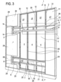
- Figures 3 to 5 show an embodiment of the invention. Since it has substantial similarities with the embodiment from Figures 1 and 2 , the same reference signs are used for parts with the same function. Where there are similarities, the description of Figures 1 and 2 shall apply accordingly to Figures 3 to 5 .
- the embodiment shown in Figures 3 to 5 differs from that shown in Figures 1 and 2 in that the support structure 2 has a first row of studs 23 and a second row of studs 24.
- the first and second stud elements 3, 12 with the first and second crossbeams 8, 9 are arranged as described in connection with Figures 1 and 2 .
- the support structure 2 has additional third stud elements 25.
- the third stud elements 25 extend continuously across the entire height of the drywall 1 and thus also cover the first, second and third wall sections 5, 6, 6', 11.
- the third stud elements 25 give the support structure 2 additional stability.
- first and second crossbeams 8, 9 laterally to a load-bearing component 13, as shown in Figure 2 .
- This allows drywalls to be constructed in any width and it is not necessary for the first and second crossbeams to be so long that they can cover the entire wall width without interruption.
- the embodiment shown in Figures 3 to 5 thus provides additional flexibility, although the two-layer design of the support structure 2 results in a somewhat greater minimum wall thickness. This embodiment is particularly suitable as a partition wall with paneling on both sides.
- the third stud element 25, like the first and second stud elements 3, 12, can be formed as metal stud profiles. Reference is made to the above description of the stud profiles, which also applies to the third stud elements 25.
- the first and second stud elements 3, 12 are arranged directly next to the third stud elements 25, almost abutting but preferably not actually contacting them.
- the first and third stud elements 3, 25 and the second and third stud elements 12, 25, respectively, are aligned parallel to each other.
- the first and second stud elements 3, 12 are each statically connected to an adjacent third stud element 25.
- panel strips 26 are provided for connection. These can be, for example, strips of planking panels.
- the planking strips 26 connect the first and third stud elements 3, 25 and the second and third stud elements 12, 25, respectively, arranged next to each other. If the stud elements are metal profiles, the profiles are preferably arranged in such a way that the flanges of both studs are next to each other.
- Figure 3 shows that the first crossbeam 8 of the second support structure bay 10 has a first and a second crossbeam profile 14, 17.
- the U stiffening channels, which have a greater material thickness and thus a higher load-bearing capacity, are generally not required, but can also be used.
- the embodiment shown in Figure 3 also has a lower installation duct 7'.
- the first crossbeam 8 does not have a second crossbeam profile 17.
- Figure 3 also shows in a section on the left how a two-layer paneling 28 can be arranged on the support structure 2.
- the position of fasteners 29, which e.g. could be formed as screws, is also shown schematically.
- the drywall 1 is on both sides completely covered with two layers of paneling 28 each.
- Figures 4 and 5 show the sections III and IV of the drywall 1 from Figure 3 .
- the double stud design of the support structure 2 can be clearly seen, having the first and third and second and third stud elements 3, 12, 25, respectively, arranged next to each other, forming double studs.
- the connection of the stud elements 3, 12, 25 with the panel strips 26 is also shown.
- Figures 4 and 5 also show how an installation, such as an electrical cable 30, can be arranged inside the drywall 1.
- the double stud design has the advantage that installations can also be guided vertically without any problems because the installation duct 7 is only present in one half of the interior space of the drywall 1. In the other half, the installation can easily be guided laterally past the crossbeams 8, 9.
- Figure 4 shows that the first and third stud elements 3, 25 can be accommodated at their lower ends in U rails 31.
- U rails 31 can also be provided at the upper end of the drywall 1 in typical manner.
- Figure 5 again clearly shows the double stud construction of the drywall 1, whereby the first and second stud elements 3, 12 and the crossbeams 8, 9 are located in the first row of studs 23.
- the continuous third stud elements 25 are provided in Figure 5 however, the second row of studs 24 is behind the first row of studs 23.
- the first crossbeam 8 comprises, as described above, a first and a second crossbeam profile 14, 17, which are formed as U channels.
- the orientation of the U channels is illustrated by dashed lines.
- the U channel 17 serves as a receiving element and guide for the installation 30. It is formed from plastic.
Landscapes
- Engineering & Computer Science (AREA)
- Architecture (AREA)
- Civil Engineering (AREA)
- Structural Engineering (AREA)
- Physics & Mathematics (AREA)
- Electromagnetism (AREA)
- Building Environments (AREA)
- Finishing Walls (AREA)
- Devices Affording Protection Of Roads Or Walls For Sound Insulation (AREA)
Claims (15)
- Cloison sèche comprenant un premier pan de mur (5) et un deuxième pan de mur (6), ainsi qu'une structure de support (2) comprenant des premiers éléments de goujon (3), dans laquelle dans la zone du premier pan de mur (5), les premiers éléments de goujon (3) sont agencés dans une rangée avec des premières distances et forment des premières travées de structure de support (4), dans laquelle un lambris (28) avec des panneaux de planches est agencé sur au moins un côté de la structure de support (2), dans laquelle un conduit d'installation (7) est agencé dans un deuxième pan de mur (6), dans laquelle la structure de support (2) a, dans la zone du deuxième pan de mur (6), une première et une seconde traverse (8, 9), qui, pour former le conduit d'installation (7), forment une seconde travée de structure de support (10) qui s'étend sur au moins deux premières travées de structure de support (4) qui sont agencées l'une à côté de l'autre, caractérisée en ce que la structure de support (2) a une première et une seconde rangée de goujons (23, 24), dans laquelle la seconde rangée de goujons (24) se trouve à côté de la première rangée de goujons (23) et derrière celle-ci et dans laquelle la première rangée de goujons (23) comprend les premiers éléments de goujon (3) et les première et seconde traverses (8, 9), et dans laquelle la seconde rangée de goujons (24) comprend des troisièmes éléments de goujon (25) qui s'étendent au moins sur le premier et le deuxième pan de mur (5, 6).
- Cloison sèche selon la revendication 1, caractérisée en ce que la cloison sèche (1) a un troisième pan de mur (11), dans laquelle la structure de support (2), dans la zone du troisième pan de mur (11), a des deuxièmes éléments de goujon (12) agencés en rangée avec des secondes distances.
- Cloison sèche selon la revendication 2, caractérisée en ce que le deuxième pan de mur (6) est situé entre les premier et troisième pans de mur (5, 11).
- Cloison sèche selon la revendication 2 ou 3, caractérisée en ce que les deuxièmes éléments de goujon (12) sont agencés debout sur la seconde traverse (9).
- Cloison sèche selon l'une quelconque des revendications 1 à 4, caractérisée en ce que la première traverse (8) est agencée sur un côté du conduit d'installation (7) et la seconde traverse (9) est agencée sur l'autre côté du conduit d'installation (7).
- Cloison sèche selon l'une quelconque des revendications 1 à 5, caractérisée en ce que la première et la seconde traverse (8, 9) s'étendent sur au moins deux des premières travées de structure de support (4).
- Cloison sèche selon l'une quelconque des revendications 1 à 6, caractérisée en ce que les première et seconde traverses (8, 9) sont agencées orthogonalement aux premiers éléments de goujon (3).
- Cloison sèche selon l'une quelconque des revendications 1 à 7, caractérisée en ce que la première et/ou la seconde traverses (8, 9) sont chacune reliées au niveau de leurs extrémités à un composant adjacent (13) de manière à supporter la charge.
- Cloison sèche selon l'une quelconque des revendications 1 à 8, caractérisée en ce que la première traverse (8) et/ou la seconde traverse (9) comprennent chacune au moins un premier profilé de traverse métallique (14), dans laquelle le profilé de traverse (14) a une première âme de profilé de traverse (15) et deux premières brides de profilé de traverse (16).
- Cloison sèche selon l'une quelconque des revendications 1 à 9, caractérisée en ce que la première et/ou la seconde traverse (8, 9) comprennent un second profilé de traverse (17) qui a une seconde âme de profilé de traverse (18) et deux secondes brides de profilé de traverse (19).
- Cloison sèche selon l'une quelconque des revendications 1 à 10, caractérisée en ce qu'un moyen de maintien de l'installation est agencé sur la première traverse (8).
- Cloison sèche selon l'une quelconque des revendications 1 à 11, caractérisée en ce que le premier élément de goujon (3) et/ou le deuxième élément de goujon (12) sont formés en tant que profilés de goujon métalliques (21) ayant chacun une âme de profilé de goujon et deux brides de profilé de goujon.
- Cloison sèche selon l'une quelconque des revendications 1 à 12, caractérisée en ce que la seconde travée de structure de support (10) s'étend de préférence sur plus de 25 %, de préférence sur plus de 50 %, plus préférablement sur plus de 70 % de la largeur de la cloison sèche, le plus préférablement sur la largeur entière de la cloison sèche.
- Cloison sèche selon la revendication 13, caractérisée en ce que les troisièmes éléments de goujon (25) sont reliés de manière statique aux premiers éléments de goujon (3) et/ou aux deuxièmes éléments de goujon (12).
- Procédé de construction d'une cloison sèche (1), caractérisé en ce qu'une structure de support (2) est construite, dans lequel, dans une zone d'un premier pan de mur (5), des premiers éléments de goujon (3) avec des premières distances sont agencés formant des premières travées de structure de support (4), caractérisé en ce que dans une zone d'un deuxième pan de mur (6), une première et une seconde traverse (8, 9) sont agencées, de sorte que, pour former un conduit d'installation (7), la structure de support (2) a une seconde travée de structure de support (10) qui s'étend sur au moins deux premières travées de structure de support (4) qui sont agencées l'une à côté de l'autre, dans lequel une installation est insérée dans le conduit d'installation (7) et dans lequel un lambris (28) de panneaux de planches est agencé sur au moins un côté de la structure de support (2), dans lequel la structure de support (2) a une première et une seconde rangée de goujons (23, 24), dans lequel la seconde rangée de goujons (24) se trouve à côté de la première rangée de goujons (23) et derrière celle-ci et dans lequel la première rangée de goujons (23) comprend les premiers éléments de goujon (3) et les première et seconde traverses (8, 9), et dans lequel la seconde rangée de goujons (24) comprend des troisièmes éléments de goujon (25) qui s'étendent au moins sur le premier et le deuxième pan de mur (5, 6).
Applications Claiming Priority (1)
| Application Number | Priority Date | Filing Date | Title |
|---|---|---|---|
| PCT/EP2019/000353 WO2021121535A1 (fr) | 2019-12-20 | 2019-12-20 | Cloison sèche et procédé de construction d'une cloison sèche |
Publications (2)
| Publication Number | Publication Date |
|---|---|
| EP4077828A1 EP4077828A1 (fr) | 2022-10-26 |
| EP4077828B1 true EP4077828B1 (fr) | 2025-03-12 |
Family
ID=69157760
Family Applications (1)
| Application Number | Title | Priority Date | Filing Date |
|---|---|---|---|
| EP19835349.2A Active EP4077828B1 (fr) | 2019-12-20 | 2019-12-20 | Cloison sèche et procédé de construction d'une cloison sèche |
Country Status (5)
| Country | Link |
|---|---|
| US (1) | US12305392B2 (fr) |
| EP (1) | EP4077828B1 (fr) |
| CA (1) | CA3156739A1 (fr) |
| MX (1) | MX2022004692A (fr) |
| WO (1) | WO2021121535A1 (fr) |
Citations (1)
| Publication number | Priority date | Publication date | Assignee | Title |
|---|---|---|---|---|
| US20190376282A1 (en) * | 2018-04-19 | 2019-12-12 | Top Life Contract Glazing, Inc. | Modular architectural wall system |
Family Cites Families (22)
| Publication number | Priority date | Publication date | Assignee | Title |
|---|---|---|---|---|
| US2321568A (en) * | 1942-01-21 | 1943-06-15 | Winfred E Wilson | Building structure |
| US2878529A (en) * | 1953-07-06 | 1959-03-24 | Raymond R Dupler | Air duct mounting device |
| US3948011A (en) * | 1972-09-29 | 1976-04-06 | Reginald Stanley Price | Partition system for a building |
| GB1446205A (en) * | 1973-06-19 | 1976-08-18 | Bendow D | Article supporting panelling |
| US4068434A (en) * | 1976-04-05 | 1978-01-17 | Day Stephen W | Composite wall panel assembly and method of production |
| US4330921A (en) * | 1978-09-21 | 1982-05-25 | White Jr Olin N | Insulated wall sections and methods of and apparatus for prefabricating the same |
| US4370838A (en) * | 1980-08-14 | 1983-02-01 | The Columbus Show Case Company | Curtain wall |
| US4709517A (en) * | 1986-06-02 | 1987-12-01 | Architectural Wall Systems, Inc. | Floor-to-ceiling wall system |
| US5127760A (en) * | 1990-07-26 | 1992-07-07 | Brady Todd A | Vertically slotted header |
| CA2120405A1 (fr) * | 1994-03-31 | 1995-10-01 | Robert S. Agar | Systeme d'ossature murale et methode de fabrication dudit systeme |
| US6684929B2 (en) * | 2002-02-15 | 2004-02-03 | Steelcase Development Corporation | Panel system |
| US6854230B2 (en) | 2003-03-13 | 2005-02-15 | Charles Starke | Continuous structural wall system |
| US20050034408A1 (en) * | 2003-07-30 | 2005-02-17 | Joseph Palumbo | Metal stud wall packaging system |
| US7032356B2 (en) * | 2003-08-19 | 2006-04-25 | Layfield Derek J | Interior wall and partition construction |
| US8752348B2 (en) * | 2005-02-25 | 2014-06-17 | Syntheon Inc. | Composite pre-formed construction articles |
| DE102005016995B3 (de) * | 2005-04-13 | 2006-08-24 | Holzbau-Gutmann Gmbh | Außenwandelement in Holzrahmenkonstruktion |
| US20080110126A1 (en) * | 2006-11-14 | 2008-05-15 | Robert Howchin | Light Weight Metal Framing Member |
| DE202012102265U1 (de) | 2012-06-19 | 2012-07-17 | Knauf Gips Kg | Trockenbauwand |
| US9702147B2 (en) * | 2013-01-07 | 2017-07-11 | Clifford Eugene Babson | Panels for framing and constructing a building structure |
| US9874014B2 (en) | 2014-11-20 | 2018-01-23 | II Henry Vernon Reed | Metal to Frame Structural Insulated Panel (M2SIP) |
| US20170121968A1 (en) * | 2015-10-08 | 2017-05-04 | Armando Sada | Prefabricated wall system |
| US10435885B2 (en) * | 2017-08-04 | 2019-10-08 | Kevin Piethman | Modular wall system |
-
2019
- 2019-12-20 CA CA3156739A patent/CA3156739A1/fr active Pending
- 2019-12-20 WO PCT/EP2019/000353 patent/WO2021121535A1/fr not_active Ceased
- 2019-12-20 MX MX2022004692A patent/MX2022004692A/es unknown
- 2019-12-20 US US17/756,702 patent/US12305392B2/en active Active
- 2019-12-20 EP EP19835349.2A patent/EP4077828B1/fr active Active
Patent Citations (1)
| Publication number | Priority date | Publication date | Assignee | Title |
|---|---|---|---|---|
| US20190376282A1 (en) * | 2018-04-19 | 2019-12-12 | Top Life Contract Glazing, Inc. | Modular architectural wall system |
Also Published As
| Publication number | Publication date |
|---|---|
| CA3156739A1 (fr) | 2021-06-24 |
| MX2022004692A (es) | 2022-05-10 |
| EP4077828A1 (fr) | 2022-10-26 |
| US20220412086A1 (en) | 2022-12-29 |
| WO2021121535A1 (fr) | 2021-06-24 |
| US12305392B2 (en) | 2025-05-20 |
Similar Documents
| Publication | Publication Date | Title |
|---|---|---|
| EP3665337B1 (fr) | Système de cloison sèche et procédé d'installation d'un tel système de cloison sèche | |
| RU2766969C2 (ru) | Модульная система для создания конструкции, соединитель модулей и конструкция, содержащая модульную систему | |
| US9249567B2 (en) | Reusable architectural wall | |
| US4881352A (en) | Wall panel arrangement | |
| US5930960A (en) | Prefab wall element with integrated chases | |
| US20050210798A1 (en) | Wall and partition construction and method including a laterally adjustable flanged stud | |
| US20130067838A1 (en) | System and method of manufacture for bulding panels | |
| US6434890B1 (en) | Room enclosure comprised or prefabricated elements such as outer walls, partitions and intermediate floors or the like and a method for the assembly thereof | |
| KR102039324B1 (ko) | 내화 칸막이 보강벽체의 시공구조 및 그 시공방법 | |
| AU6267999A (en) | Floor joist and support system therefor | |
| CZ288411B6 (en) | System for making a wall | |
| US8997418B2 (en) | Load supporting blocking member for use in a metal stud wall | |
| US20150176274A1 (en) | System and method for lateral transfer plate having a punched tab | |
| EP4077828B1 (fr) | Cloison sèche et procédé de construction d'une cloison sèche | |
| US20220074199A1 (en) | Unitary double stud assembly for sound damping wall | |
| JP5588920B2 (ja) | 内装下地構造の形成方法 | |
| US20060207201A1 (en) | Panel system and method | |
| US20060000182A1 (en) | Wall stud assembly for modular walls | |
| CN210562591U (zh) | 墙体模块与墙体模块之间的连接节点结构及装配式建筑 | |
| CN210562590U (zh) | 墙体模块与角柱的连接节点结构及装配式建筑 | |
| CA2776267C (fr) | Supports et couvercles pour acheminement de fils electriques aux coins interieurs d'un batiment | |
| FI93250C (fi) | Liitoselementti ja sen käyttö | |
| RU2793696C1 (ru) | Соединительная конструкция между перегородками и плитой перекрытия и способ для ее изготовления | |
| CN210562589U (zh) | 装配式建筑及框架体 | |
| WO2014195723A1 (fr) | Système de mur non-porteur |
Legal Events
| Date | Code | Title | Description |
|---|---|---|---|
| STAA | Information on the status of an ep patent application or granted ep patent |
Free format text: STATUS: UNKNOWN |
|
| STAA | Information on the status of an ep patent application or granted ep patent |
Free format text: STATUS: THE INTERNATIONAL PUBLICATION HAS BEEN MADE |
|
| PUAI | Public reference made under article 153(3) epc to a published international application that has entered the european phase |
Free format text: ORIGINAL CODE: 0009012 |
|
| STAA | Information on the status of an ep patent application or granted ep patent |
Free format text: STATUS: REQUEST FOR EXAMINATION WAS MADE |
|
| 17P | Request for examination filed |
Effective date: 20220519 |
|
| AK | Designated contracting states |
Kind code of ref document: A1 Designated state(s): AL AT BE BG CH CY CZ DE DK EE ES FI FR GB GR HR HU IE IS IT LI LT LU LV MC MK MT NL NO PL PT RO RS SE SI SK SM TR |
|
| DAV | Request for validation of the european patent (deleted) | ||
| DAX | Request for extension of the european patent (deleted) | ||
| STAA | Information on the status of an ep patent application or granted ep patent |
Free format text: STATUS: EXAMINATION IS IN PROGRESS |
|
| 17Q | First examination report despatched |
Effective date: 20240122 |
|
| 17Q | First examination report despatched |
Effective date: 20240208 |
|
| GRAP | Despatch of communication of intention to grant a patent |
Free format text: ORIGINAL CODE: EPIDOSNIGR1 |
|
| STAA | Information on the status of an ep patent application or granted ep patent |
Free format text: STATUS: GRANT OF PATENT IS INTENDED |
|
| INTG | Intention to grant announced |
Effective date: 20241015 |
|
| GRAS | Grant fee paid |
Free format text: ORIGINAL CODE: EPIDOSNIGR3 |
|
| GRAA | (expected) grant |
Free format text: ORIGINAL CODE: 0009210 |
|
| STAA | Information on the status of an ep patent application or granted ep patent |
Free format text: STATUS: THE PATENT HAS BEEN GRANTED |
|
| AK | Designated contracting states |
Kind code of ref document: B1 Designated state(s): AL AT BE BG CH CY CZ DE DK EE ES FI FR GB GR HR HU IE IS IT LI LT LU LV MC MK MT NL NO PL PT RO RS SE SI SK SM TR |
|
| REG | Reference to a national code |
Ref country code: GB Ref legal event code: FG4D |
|
| REG | Reference to a national code |
Ref country code: CH Ref legal event code: EP |
|
| REG | Reference to a national code |
Ref country code: DE Ref legal event code: R096 Ref document number: 602019067263 Country of ref document: DE |
|
| REG | Reference to a national code |
Ref country code: IE Ref legal event code: FG4D |
|
| P01 | Opt-out of the competence of the unified patent court (upc) registered |
Free format text: CASE NUMBER: APP_19199/2025 Effective date: 20250422 |
|
| PG25 | Lapsed in a contracting state [announced via postgrant information from national office to epo] |
Ref country code: RS Free format text: LAPSE BECAUSE OF FAILURE TO SUBMIT A TRANSLATION OF THE DESCRIPTION OR TO PAY THE FEE WITHIN THE PRESCRIBED TIME-LIMIT Effective date: 20250612 |
|
| PG25 | Lapsed in a contracting state [announced via postgrant information from national office to epo] |
Ref country code: FI Free format text: LAPSE BECAUSE OF FAILURE TO SUBMIT A TRANSLATION OF THE DESCRIPTION OR TO PAY THE FEE WITHIN THE PRESCRIBED TIME-LIMIT Effective date: 20250312 |
|
| PG25 | Lapsed in a contracting state [announced via postgrant information from national office to epo] |
Ref country code: ES Free format text: LAPSE BECAUSE OF FAILURE TO SUBMIT A TRANSLATION OF THE DESCRIPTION OR TO PAY THE FEE WITHIN THE PRESCRIBED TIME-LIMIT Effective date: 20250312 |
|
| REG | Reference to a national code |
Ref country code: LT Ref legal event code: MG9D |
|
| PG25 | Lapsed in a contracting state [announced via postgrant information from national office to epo] |
Ref country code: NO Free format text: LAPSE BECAUSE OF FAILURE TO SUBMIT A TRANSLATION OF THE DESCRIPTION OR TO PAY THE FEE WITHIN THE PRESCRIBED TIME-LIMIT Effective date: 20250612 |
|
| PG25 | Lapsed in a contracting state [announced via postgrant information from national office to epo] |
Ref country code: HR Free format text: LAPSE BECAUSE OF FAILURE TO SUBMIT A TRANSLATION OF THE DESCRIPTION OR TO PAY THE FEE WITHIN THE PRESCRIBED TIME-LIMIT Effective date: 20250312 |
|
| REG | Reference to a national code |
Ref country code: NL Ref legal event code: MP Effective date: 20250312 |
|
| PG25 | Lapsed in a contracting state [announced via postgrant information from national office to epo] |
Ref country code: LV Free format text: LAPSE BECAUSE OF FAILURE TO SUBMIT A TRANSLATION OF THE DESCRIPTION OR TO PAY THE FEE WITHIN THE PRESCRIBED TIME-LIMIT Effective date: 20250312 |
|
| PG25 | Lapsed in a contracting state [announced via postgrant information from national office to epo] |
Ref country code: GR Free format text: LAPSE BECAUSE OF FAILURE TO SUBMIT A TRANSLATION OF THE DESCRIPTION OR TO PAY THE FEE WITHIN THE PRESCRIBED TIME-LIMIT Effective date: 20250613 Ref country code: BG Free format text: LAPSE BECAUSE OF FAILURE TO SUBMIT A TRANSLATION OF THE DESCRIPTION OR TO PAY THE FEE WITHIN THE PRESCRIBED TIME-LIMIT Effective date: 20250312 |
|
| REG | Reference to a national code |
Ref country code: AT Ref legal event code: MK05 Ref document number: 1775113 Country of ref document: AT Kind code of ref document: T Effective date: 20250312 |
|
| PG25 | Lapsed in a contracting state [announced via postgrant information from national office to epo] |
Ref country code: NL Free format text: LAPSE BECAUSE OF FAILURE TO SUBMIT A TRANSLATION OF THE DESCRIPTION OR TO PAY THE FEE WITHIN THE PRESCRIBED TIME-LIMIT Effective date: 20250312 |
|
| PG25 | Lapsed in a contracting state [announced via postgrant information from national office to epo] |
Ref country code: SE Free format text: LAPSE BECAUSE OF FAILURE TO SUBMIT A TRANSLATION OF THE DESCRIPTION OR TO PAY THE FEE WITHIN THE PRESCRIBED TIME-LIMIT Effective date: 20250312 |
|
| PG25 | Lapsed in a contracting state [announced via postgrant information from national office to epo] |
Ref country code: SM Free format text: LAPSE BECAUSE OF FAILURE TO SUBMIT A TRANSLATION OF THE DESCRIPTION OR TO PAY THE FEE WITHIN THE PRESCRIBED TIME-LIMIT Effective date: 20250312 |
|
| PG25 | Lapsed in a contracting state [announced via postgrant information from national office to epo] |
Ref country code: PT Free format text: LAPSE BECAUSE OF FAILURE TO SUBMIT A TRANSLATION OF THE DESCRIPTION OR TO PAY THE FEE WITHIN THE PRESCRIBED TIME-LIMIT Effective date: 20250714 |
|
| PG25 | Lapsed in a contracting state [announced via postgrant information from national office to epo] |
Ref country code: IT Free format text: LAPSE BECAUSE OF FAILURE TO SUBMIT A TRANSLATION OF THE DESCRIPTION OR TO PAY THE FEE WITHIN THE PRESCRIBED TIME-LIMIT Effective date: 20250312 Ref country code: PL Free format text: LAPSE BECAUSE OF FAILURE TO SUBMIT A TRANSLATION OF THE DESCRIPTION OR TO PAY THE FEE WITHIN THE PRESCRIBED TIME-LIMIT Effective date: 20250312 |
|
| PG25 | Lapsed in a contracting state [announced via postgrant information from national office to epo] |
Ref country code: AT Free format text: LAPSE BECAUSE OF FAILURE TO SUBMIT A TRANSLATION OF THE DESCRIPTION OR TO PAY THE FEE WITHIN THE PRESCRIBED TIME-LIMIT Effective date: 20250312 |
|
| PG25 | Lapsed in a contracting state [announced via postgrant information from national office to epo] |
Ref country code: CZ Free format text: LAPSE BECAUSE OF FAILURE TO SUBMIT A TRANSLATION OF THE DESCRIPTION OR TO PAY THE FEE WITHIN THE PRESCRIBED TIME-LIMIT Effective date: 20250312 Ref country code: EE Free format text: LAPSE BECAUSE OF FAILURE TO SUBMIT A TRANSLATION OF THE DESCRIPTION OR TO PAY THE FEE WITHIN THE PRESCRIBED TIME-LIMIT Effective date: 20250312 |
|
| PG25 | Lapsed in a contracting state [announced via postgrant information from national office to epo] |
Ref country code: RO Free format text: LAPSE BECAUSE OF FAILURE TO SUBMIT A TRANSLATION OF THE DESCRIPTION OR TO PAY THE FEE WITHIN THE PRESCRIBED TIME-LIMIT Effective date: 20250312 |
|
| PG25 | Lapsed in a contracting state [announced via postgrant information from national office to epo] |
Ref country code: SK Free format text: LAPSE BECAUSE OF FAILURE TO SUBMIT A TRANSLATION OF THE DESCRIPTION OR TO PAY THE FEE WITHIN THE PRESCRIBED TIME-LIMIT Effective date: 20250312 |
|
| PG25 | Lapsed in a contracting state [announced via postgrant information from national office to epo] |
Ref country code: IS Free format text: LAPSE BECAUSE OF FAILURE TO SUBMIT A TRANSLATION OF THE DESCRIPTION OR TO PAY THE FEE WITHIN THE PRESCRIBED TIME-LIMIT Effective date: 20250712 |
|
| REG | Reference to a national code |
Ref country code: DE Ref legal event code: R097 Ref document number: 602019067263 Country of ref document: DE |
|
| PG25 | Lapsed in a contracting state [announced via postgrant information from national office to epo] |
Ref country code: DK Free format text: LAPSE BECAUSE OF FAILURE TO SUBMIT A TRANSLATION OF THE DESCRIPTION OR TO PAY THE FEE WITHIN THE PRESCRIBED TIME-LIMIT Effective date: 20250312 |
|
| PLBE | No opposition filed within time limit |
Free format text: ORIGINAL CODE: 0009261 |
|
| STAA | Information on the status of an ep patent application or granted ep patent |
Free format text: STATUS: NO OPPOSITION FILED WITHIN TIME LIMIT |
|
| REG | Reference to a national code |
Ref country code: CH Ref legal event code: L10 Free format text: ST27 STATUS EVENT CODE: U-0-0-L10-L00 (AS PROVIDED BY THE NATIONAL OFFICE) Effective date: 20260121 |
|
| 26N | No opposition filed |
Effective date: 20251215 |
|
| PGFP | Annual fee paid to national office [announced via postgrant information from national office to epo] |
Ref country code: DE Payment date: 20251229 Year of fee payment: 7 |