EP4077897B1 - Gemischzuführsystem für einen verbrennungsmotor mit quantitativer gemischregelung - Google Patents
Gemischzuführsystem für einen verbrennungsmotor mit quantitativer gemischregelung Download PDFInfo
- Publication number
- EP4077897B1 EP4077897B1 EP20817043.1A EP20817043A EP4077897B1 EP 4077897 B1 EP4077897 B1 EP 4077897B1 EP 20817043 A EP20817043 A EP 20817043A EP 4077897 B1 EP4077897 B1 EP 4077897B1
- Authority
- EP
- European Patent Office
- Prior art keywords
- valve
- supply system
- bypass
- mixture supply
- turbocharger
- Prior art date
- Legal status (The legal status is an assumption and is not a legal conclusion. Google has not performed a legal analysis and makes no representation as to the accuracy of the status listed.)
- Active
Links
Images


Classifications
-
- F—MECHANICAL ENGINEERING; LIGHTING; HEATING; WEAPONS; BLASTING
- F02—COMBUSTION ENGINES; HOT-GAS OR COMBUSTION-PRODUCT ENGINE PLANTS
- F02D—CONTROLLING COMBUSTION ENGINES
- F02D41/00—Electrical control of supply of combustible mixture or its constituents
- F02D41/0002—Controlling intake air
- F02D41/0007—Controlling intake air for control of turbo-charged or super-charged engines
-
- F—MECHANICAL ENGINEERING; LIGHTING; HEATING; WEAPONS; BLASTING
- F02—COMBUSTION ENGINES; HOT-GAS OR COMBUSTION-PRODUCT ENGINE PLANTS
- F02B—INTERNAL-COMBUSTION PISTON ENGINES; COMBUSTION ENGINES IN GENERAL
- F02B29/00—Engines characterised by provision for charging or scavenging not provided for in groups F02B25/00, F02B27/00 or F02B33/00 - F02B39/00; Details thereof
- F02B29/04—Cooling of air intake supply
- F02B29/0406—Layout of the intake air cooling or coolant circuit
- F02B29/0412—Multiple heat exchangers arranged in parallel or in series
-
- F—MECHANICAL ENGINEERING; LIGHTING; HEATING; WEAPONS; BLASTING
- F02—COMBUSTION ENGINES; HOT-GAS OR COMBUSTION-PRODUCT ENGINE PLANTS
- F02B—INTERNAL-COMBUSTION PISTON ENGINES; COMBUSTION ENGINES IN GENERAL
- F02B37/00—Engines characterised by provision of pumps driven at least for part of the time by exhaust
- F02B37/004—Engines characterised by provision of pumps driven at least for part of the time by exhaust with exhaust drives arranged in series
-
- F—MECHANICAL ENGINEERING; LIGHTING; HEATING; WEAPONS; BLASTING
- F02—COMBUSTION ENGINES; HOT-GAS OR COMBUSTION-PRODUCT ENGINE PLANTS
- F02B—INTERNAL-COMBUSTION PISTON ENGINES; COMBUSTION ENGINES IN GENERAL
- F02B37/00—Engines characterised by provision of pumps driven at least for part of the time by exhaust
- F02B37/013—Engines characterised by provision of pumps driven at least for part of the time by exhaust with exhaust-driven pumps arranged in series
-
- F—MECHANICAL ENGINEERING; LIGHTING; HEATING; WEAPONS; BLASTING
- F02—COMBUSTION ENGINES; HOT-GAS OR COMBUSTION-PRODUCT ENGINE PLANTS
- F02B—INTERNAL-COMBUSTION PISTON ENGINES; COMBUSTION ENGINES IN GENERAL
- F02B37/00—Engines characterised by provision of pumps driven at least for part of the time by exhaust
- F02B37/12—Control of the pumps
- F02B37/16—Control of the pumps by bypassing charging air
- F02B37/162—Control of the pumps by bypassing charging air by bypassing, e.g. partially, intake air from pump inlet to pump outlet
-
- F—MECHANICAL ENGINEERING; LIGHTING; HEATING; WEAPONS; BLASTING
- F02—COMBUSTION ENGINES; HOT-GAS OR COMBUSTION-PRODUCT ENGINE PLANTS
- F02B—INTERNAL-COMBUSTION PISTON ENGINES; COMBUSTION ENGINES IN GENERAL
- F02B37/00—Engines characterised by provision of pumps driven at least for part of the time by exhaust
- F02B37/12—Control of the pumps
- F02B37/18—Control of the pumps by bypassing exhaust from the inlet to the outlet of turbine or to the atmosphere
-
- F—MECHANICAL ENGINEERING; LIGHTING; HEATING; WEAPONS; BLASTING
- F02—COMBUSTION ENGINES; HOT-GAS OR COMBUSTION-PRODUCT ENGINE PLANTS
- F02D—CONTROLLING COMBUSTION ENGINES
- F02D13/00—Controlling the engine output power by varying inlet or exhaust valve operating characteristics, e.g. timing
- F02D13/02—Controlling the engine output power by varying inlet or exhaust valve operating characteristics, e.g. timing during engine operation
- F02D13/0223—Variable control of the intake valves only
-
- F—MECHANICAL ENGINEERING; LIGHTING; HEATING; WEAPONS; BLASTING
- F02—COMBUSTION ENGINES; HOT-GAS OR COMBUSTION-PRODUCT ENGINE PLANTS
- F02D—CONTROLLING COMBUSTION ENGINES
- F02D19/00—Controlling engines characterised by their use of non-liquid fuels, pluralities of fuels, or non-fuel substances added to the combustible mixtures
- F02D19/02—Controlling engines characterised by their use of non-liquid fuels, pluralities of fuels, or non-fuel substances added to the combustible mixtures peculiar to engines working with gaseous fuels
-
- F—MECHANICAL ENGINEERING; LIGHTING; HEATING; WEAPONS; BLASTING
- F02—COMBUSTION ENGINES; HOT-GAS OR COMBUSTION-PRODUCT ENGINE PLANTS
- F02D—CONTROLLING COMBUSTION ENGINES
- F02D41/00—Electrical control of supply of combustible mixture or its constituents
- F02D41/0025—Controlling engines characterised by use of non-liquid fuels, pluralities of fuels, or non-fuel substances added to the combustible mixtures
- F02D41/0027—Controlling engines characterised by use of non-liquid fuels, pluralities of fuels, or non-fuel substances added to the combustible mixtures the fuel being gaseous
-
- F—MECHANICAL ENGINEERING; LIGHTING; HEATING; WEAPONS; BLASTING
- F02—COMBUSTION ENGINES; HOT-GAS OR COMBUSTION-PRODUCT ENGINE PLANTS
- F02D—CONTROLLING COMBUSTION ENGINES
- F02D41/00—Electrical control of supply of combustible mixture or its constituents
- F02D41/0002—Controlling intake air
- F02D2041/001—Controlling intake air for engines with variable valve actuation
-
- F—MECHANICAL ENGINEERING; LIGHTING; HEATING; WEAPONS; BLASTING
- F02—COMBUSTION ENGINES; HOT-GAS OR COMBUSTION-PRODUCT ENGINE PLANTS
- F02D—CONTROLLING COMBUSTION ENGINES
- F02D41/00—Electrical control of supply of combustible mixture or its constituents
- F02D41/0002—Controlling intake air
- F02D2041/002—Controlling intake air by simultaneous control of throttle and variable valve actuation
-
- F—MECHANICAL ENGINEERING; LIGHTING; HEATING; WEAPONS; BLASTING
- F02—COMBUSTION ENGINES; HOT-GAS OR COMBUSTION-PRODUCT ENGINE PLANTS
- F02D—CONTROLLING COMBUSTION ENGINES
- F02D41/00—Electrical control of supply of combustible mixture or its constituents
- F02D41/0025—Controlling engines characterised by use of non-liquid fuels, pluralities of fuels, or non-fuel substances added to the combustible mixtures
-
- Y—GENERAL TAGGING OF NEW TECHNOLOGICAL DEVELOPMENTS; GENERAL TAGGING OF CROSS-SECTIONAL TECHNOLOGIES SPANNING OVER SEVERAL SECTIONS OF THE IPC; TECHNICAL SUBJECTS COVERED BY FORMER USPC CROSS-REFERENCE ART COLLECTIONS [XRACs] AND DIGESTS
- Y02—TECHNOLOGIES OR APPLICATIONS FOR MITIGATION OR ADAPTATION AGAINST CLIMATE CHANGE
- Y02T—CLIMATE CHANGE MITIGATION TECHNOLOGIES RELATED TO TRANSPORTATION
- Y02T10/00—Road transport of goods or passengers
- Y02T10/10—Internal combustion engine [ICE] based vehicles
- Y02T10/12—Improving ICE efficiencies
-
- Y—GENERAL TAGGING OF NEW TECHNOLOGICAL DEVELOPMENTS; GENERAL TAGGING OF CROSS-SECTIONAL TECHNOLOGIES SPANNING OVER SEVERAL SECTIONS OF THE IPC; TECHNICAL SUBJECTS COVERED BY FORMER USPC CROSS-REFERENCE ART COLLECTIONS [XRACs] AND DIGESTS
- Y02—TECHNOLOGIES OR APPLICATIONS FOR MITIGATION OR ADAPTATION AGAINST CLIMATE CHANGE
- Y02T—CLIMATE CHANGE MITIGATION TECHNOLOGIES RELATED TO TRANSPORTATION
- Y02T10/00—Road transport of goods or passengers
- Y02T10/10—Internal combustion engine [ICE] based vehicles
- Y02T10/30—Use of alternative fuels, e.g. biofuels
Definitions
- the invention relates to a mixture supply system for an internal combustion engine with quantitative mixture control, and a method for operating a mixture supply system for an internal combustion engine with quantitative mixture control.
- VVTG variable turbine geometry
- WO 2008/000899 A1 a control arrangement for a gas exchange valve in a piston engine.
- a hydraulic medium is provided to delay the closing of the valve.
- WO 2017/023333 A1 discloses an extension of the intake valve opening duration when the load increases, combined with a closing of a bypass valve of a charging device.
- Some of these systems can provide partial or complete variability of the timing of the intake valve, but not with the speed required to control excess air conditions.
- Devices for controlling the timing of the intake valve closing therefore have the disadvantage that they are often slow and sluggish, or that fast-reacting systems are very complex and expensive.
- a mixture supply system for an internal combustion engine with quantitative mixture control in particular a gas engine or a dual-fuel engine
- the mixture supply system has a A charging system that can be connected to an internal combustion engine, comprising a bypass and a bypass valve arranged in the bypass.
- the mixture supply system also has a valve train for periodically actuating an intake valve of the internal combustion engine, wherein a valve control time of the intake valve can be controlled by the valve train.
- the mixture supply system is designed to at least partially close the bypass valve when an engine load increases and to change the valve control time to extend the valve opening duration, and to at least partially open the bypass valve during and/or after a valve train latency period has elapsed; and/or to at least partially open the bypass valve when the engine load decreases and to change the valve control time to shorten the valve opening duration, and to at least partially close the bypass valve during and/or after a valve train latency period has elapsed.
- the mixture supply system can therefore be set up to partially close the bypass valve or reduce the degree of opening of the bypass valve when the engine load increases.
- the turbocharger pressure or the delivery pressure decreases, but not to the extent required to maintain the excess air ratio within defined limits. Therefore, the mixture supply system can be set up to partially open the bypass valve or increase the degree of opening of the bypass valve when the engine load decreases.
- the valve train latency corresponds to a period of time between a change in the valve timing and a point in time at which the change in the valve timing takes full effect.
- the valve train can have a certain inertia, i.e. after a change in the valve timing of the intake valve, a certain amount of time can pass until the change in the valve timing occurs in the desired way.
- valve train latency period lasts longer than a single working cycle.
- a typical valve train latency period can be, for example, about 5-10 working cycles.
- the bypass valve arranged in the bypass is advantageously designed to react quickly, in particular within a fraction of a valve train latency time.
- the bypass valve arranged in the bypass is advantageously designed to react quickly, in particular within a fraction of a valve train latency time.
- the excess air ratio in the cylinders can be adjusted within the operating limits during the valve train latency time.
- the mixture supply system can be designed to at least partially open the bypass valve. This advantageously makes it possible to control the excess air ratio predominantly or even completely by the valve train during or after the valve train latency time has elapsed.
- the mixture supply system is designed to at least partially close the bypass valve immediately when the engine load increases and to change the valve control time to extend the valve opening time (and correspondingly to at least partially open the bypass valve immediately when the engine load decreases and to change the valve control time to shorten the valve opening time).
- the bypass valve is at least partially closed and the valve control time is changed essentially at the same time; thus, the bypass valve and the valve control time are controlled essentially simultaneously (typically within the same working cycle). This enables pre-compensation of the rather sluggish valve train (which requires several working cycles after control until the change in the valve control time occurs in the desired way) by the much faster-reacting bypass valve in order to operate within operating limits.
- the mixture supply system is configured such that, as the engine load increases, the bypass valve is opened in a first half of the valve train latency to at least partially close and/or to at least partially open the bypass valve in the first half of the valve train latency period when the engine load is reduced.
- the excess air ratio in the cylinders can be adjusted within the operating limits during the valve train latency period.
- the mixture supply system can be configured to at least partially close the bypass valve.
- this makes it possible to control the excess air ratio predominantly or even completely by the valve train during or after the valve train latency period.
- the bypass valve can be slightly open or almost closed.
- the degree of opening of the bypass valve can be very small at a constant engine load. This makes it possible for the bypass valve to be closed further when the engine load increases, i.e. the degree of opening of the bypass valve can be reduced.
- the degree of opening of the bypass valve according to embodiments of the present disclosure is significantly smaller than in mixture supply systems that have a bypass valve but do not provide additional means for adjusting the excess air ratio.
- bypass valve can be slightly open or almost closed at a constant or stationary engine load, it is possible for energy losses, in particular due to wasted enthalpy on a turbine side of the turbocharger or recirculation losses on a compressor side of the turbocharger, to be very small. In particular in large, medium-speed internal combustion engines, the reduction of energy losses, and thus lower fuel consumption, is of considerable importance.
- the mixture supply system is designed to at least partially open the bypass valve during and/or after the expiration of a valve train latency time or to adjust the degree of opening of the bypass valve in such a way that in the event of a renewed increase in the engine load, the bypass can be sufficiently closed. or the degree of opening of the bypass valve can be sufficiently reduced.
- a first degree of opening of the bypass valve before the increase in engine load and a second degree of opening during and/or after the valve train latency period have elapsed are essentially the same.
- a definable degree of opening can be provided for a stationary engine load, wherein during and/or after the valve train latency period have elapsed, the mixture supply system can be set to adjust the definable degree of opening.
- the mixture supply system can be provided to at least partially close the bypass valve in the event of an abrupt increase in the engine load and to change the valve control time to extend the valve opening duration, and to at least partially open the bypass valve during and/or after the valve train latency period has elapsed.
- the degree of opening of the bypass valve can be provided to remain unchanged.
- the mixture supply system can be set up to change the valve control time to extend the valve opening duration.
- the mixture supply system has a control unit.
- the control unit can be set up to adjust the degree of opening of the bypass valve and/or to change the valve control time of the intake valve by means of the valve train.
- the control unit can be set up to adjust the degree of opening of the bypass valve and to change the valve control time of the intake valve by means of the valve train when the engine load increases and/or when the engine load decreases.
- the control unit can also be set up to adjust the degree of opening of the bypass valve during and/or after the valve train latency time has elapsed, depending on a parameter.
- the parameter can be suitable for determining whether the valve train latency time has elapsed.
- the parameter can be suitable for determining an amount of air and/or mixture required by means of the bypass or for determining a reduction in the amount of air and/or mixture required by means of the bypass.
- the parameter can be a fuel-air ratio or a fuel-air ratio estimated from measured variables in a combustion chamber of the internal combustion engine.
- the parameter is a boost pressure.
- the boost pressure represents the amount of air in the cylinder.
- the bypass valve can be a throttle valve. Furthermore, the bypass valve can be adjustable stepwise or continuously.
- the control unit can also be set up to adjust the degree of opening of the bypass valve stepwise or continuously during and/or after the valve train latency period has elapsed. During the valve train latency period, the change in the valve control time can take effect stepwise or continuously until the change in the valve control time takes full effect at the end of the period.
- the control unit can also be set up to adjust the degree of opening of the bypass valve stepwise or continuously depending on the parameter during and/or after the valve train latency period has elapsed.
- the charging system can have one or more turbochargers.
- Each turbocharger can have a compressor and a turbine connected to the compressor by means of a turbocharger shaft.
- the charging system can be connected to an intake manifold and/or an exhaust manifold of the internal combustion engine with quantitative mixture control.
- an outlet region of the compressor can be connected to the intake manifold and an inlet region of the turbine can be connected to the exhaust manifold.
- a charge air cooler and/or a throttle device for example a throttle valve, can be arranged in a connecting line connected to the outlet region of the compressor and connectable to the intake manifold.
- An air intake device and/or a gas mixer can be connected to an inlet region of the compressor, the gas mixer having the air intake device and a gas supply.
- the bypass can connect the outlet area of the compressor with the inlet area of the compressor and/or the bypass can connect the inlet area of the turbine with the outlet area of the turbine.
- the "and" case is to be understood as meaning that the bypass has two separate lines, an air return line or mixture return line and an exhaust gas bypass line. Both the air return line or mixture return line and the exhaust gas bypass line preferably each have a bypass valve.
- the charging system may further comprise at least two turbochargers, wherein the bypass connects an inlet region of a turbine of the first turbocharger with an outlet region of a turbine of the second turbocharger and/or an outlet region of a compressor of the first turbocharger with an inlet area of a compressor of the second turbocharger.
- the charging system can have a low-pressure turbocharger and a high-pressure turbocharger.
- the air intake device and/or the gas mixer can be connected to an inlet region of the low-pressure compressor, the gas mixer having the air intake device and the gas supply.
- the charging system can have a line for connecting an outlet region of the low-pressure compressor to an inlet region of the high-pressure compressor.
- An intercooler can be arranged in the line.
- the valve train can be set up to shift the timing of the actuation of the intake valve. This allows the valve stroke to be shifted over time, in particular to control the cylinder charge.
- the timing of the closing movement of the intake valve can be infinitely adjustable. This enables precise adjustment of the cylinder filling, in particular the cylinder pressure. This also allows the individual cylinders to be set equal to one another.
- the valve train can be designed to shift the closing movement of the intake valve over time.
- the shifting of the closing movement of the intake valve over time can be infinitely adjustable. This enables precise adjustment of the filling of the cylinder, in particular the cylinder pressure.
- the valve train further comprises a delay element for shifting the closing movement of the intake valve.
- the delay element can be a mechanical or a hydraulic delay element.
- the delay element can comprise a hydraulic chamber for shifting the closing movement of the intake valve by means of a hydraulic medium.
- the valve train can comprise an intake valve actuating mechanism, wherein the intake valve actuating mechanism can be arranged in contact with the delay element for temporally shifting a closing movement of the intake valve.
- the intake valve actuating mechanism can comprise at least one selected from a rocker arm, a drag lever, a push rod and a valve bridge, wherein the delay element can be in contact with the rocker arm or the drag lever or the push rod or the valve bridge.
- valve lift can also be adjusted to control the cylinder charge.
- the valve train can thus be set up to adjust the valve lift.
- the internal combustion engine with quantitative mixture control can be a stationary internal combustion engine or a drive engine.
- the internal combustion engine can be a gasoline engine, in particular the internal combustion engine can be a four-stroke engine.
- the internal combustion engine with quantitative mixture control can be a gas engine or a dual-fuel engine. Gas can be supplied to the gas engine or the dual-fuel engine via the charging system by means of the gas supply connected to the gas mixer and/or via a separate gas injection, in particular via the gas injection connected to the intake manifold.
- the gas injection can also take place via an intake channel arranged between the intake manifold and the cylinder (intake manifold injection).
- an internal combustion engine with quantitative mixture control in particular a gas engine or a dual-fuel engine.
- the internal combustion engine has a mixture supply system according to one of the embodiments described herein.
- the internal combustion engine can have a plurality of cylinders and a valve train for periodically actuating one or more intake valves for each cylinder of the internal combustion engine.
- the embodiments described here can be implemented with minimal design effort, in particular for mixture supply systems that already have valve trains in which a valve control time of the intake valve can be controlled by the valve train. This makes it possible to achieve an improved mixture supply system in a simple and cost-effective manner.
- a method for operating a mixture supply system for an internal combustion engine with quantitative mixture control can be a gas engine or a dual-fuel engine.
- the mixture supply system has a charging system that can be connected to the internal combustion engine and has a bypass and a bypass valve arranged in the bypass.
- the mixture supply system has a valve train for periodically actuating an intake valve of the internal combustion engine, wherein a valve control time of the intake valve can be controlled by the valve train.
- the internal combustion engine can have the mixture supply system according to one of the embodiments described herein.
- Step A2) occurs after step A1).
- Step B2) occurs after step B1).
- Steps A2) and/or B2) can be adjusted depending on the fuel-air ratio.
- FIGS. 1 to 4 show - in a schematic representation - parts of various embodiments of a mixture supply system 100, 300, 400, 500 according to the invention for an internal combustion engine 200 with quantitative mixture control, in particular a gas engine or a dual-fuel engine.
- the dashed arrows in the Figures 1 to 4 indicate the assignment of the reference symbols to the features.
- the bold arrows drawn as solid lines in the Figures 1 to 4 indicate a flow direction.
- the figures illustrate parts of the mixture supply system 100, 300, 400, 500 according to the invention, in particular a charging system 110, 310, 410, 510, and show, by way of example, parts of the internal combustion engine that can be connected to the mixture supply system 100, 300, 400, 500.
- Figure 1 illustrates the mixture supply system 100.
- the mixture supply system 100 has a valve train for periodically actuating an intake valve of the internal combustion engine 200, wherein a valve control time of the intake valve is controllable by the valve train (not shown).
- the mixture supply system 100 also has a charging system 110 that can be connected to the internal combustion engine 200.
- the charging system can comprise a turbocharger 140, the turbocharger having a compressor 111 and a turbine 112 connected by means of a turbocharger shaft 113.
- An inlet region of the turbine 112 can be connected to an exhaust manifold 230.
- An outlet region of the compressor 111 can be connected to an inlet manifold 220 of the internal combustion engine 200 by means of a connecting line.
- a charge air cooler 116 and/or a throttle valve 117 can be connected in the connecting line.
- a gas mixer 127 can be connected to an inlet region of the compressor 111, the gas mixer 127 having a gas supply 114 and/or an air intake device 115.
- the charging system 110 has a bypass 120.
- the bypass 120 can have a mixture return line 122 and an exhaust bypass line 123.
- a bypass valve 121, 124 is arranged in the bypass.
- a bypass valve 121, 124 is arranged in the mixture return line 122 and in the exhaust bypass line 123.
- the bypass 120 can connect the inlet region of the turbine 112 of the turbocharger 140 to the outlet region of the turbine 112 of the turbocharger 140 and the outlet region of the compressor 111 of the turbocharger 140 to the inlet region of the compressor 111 of the turbocharger 140.
- the internal combustion engine 200 can have at least one cylinder 210.
- the at least one cylinder can be connected to the intake manifold 220 and/or the exhaust manifold 230.
- the internal combustion engine 200 can have at least one intake valve, wherein the intake valve can be arranged between the intake manifold 220 and the cylinder 210 (not shown).
- the intake valve can be periodically actuated by the valve train, wherein a valve control time of the intake valve can be controlled by the valve train.
- Gas can be supplied to the internal combustion engine 200 via the charging system 110 by means of the gas supply 114 connected to the gas mixer 127 and/or via a separate gas injection 201, in particular via the gas injection 201 connected to the intake manifold 220.
- Figure 2 illustrates the mixture supply system 300.
- the mixture supply system 300 has a valve train for periodically actuating an intake valve of the internal combustion engine 200, wherein a valve control time of the intake valve is controllable by the valve train (not shown).
- the mixture supply system 300 also has a charging system 310 that can be connected to the internal combustion engine 200.
- the charging system 310 can comprise a low-pressure turbocharger 330, the low-pressure turbocharger 330 having a low-pressure compressor 319 and a low-pressure turbine 326 connected by means of a low-pressure turbocharger shaft 325.
- a gas mixer 327 can be connected to an inlet region of the low-pressure compressor 319, the gas mixer 327 having a gas supply 314 and/or an air intake device 315.
- the charging system 310 may include a high-pressure turbocharger 340, wherein the high-pressure turbocharger 340 has a high-pressure compressor 311 and a high-pressure turbine 312 connected by a turbocharger shaft 313.
- the charging system 310 may include a line for connecting an outlet region of the low-pressure compressor 319 to an inlet region of the high-pressure compressor 311.
- An intercooler 318 may be arranged in the line.
- An inlet region of the high pressure turbine 312 may be connectable to an exhaust manifold 230.
- An outlet region of the high pressure turbine 312 may be connected to an inlet region of the low pressure turbine 326.
- An outlet region of the high-pressure compressor 311 can be connected to an intake manifold 220 of the internal combustion engine 200 by means of a connecting line.
- a charge air cooler 316 and/or a throttle valve 317 can be connected in the connecting line.
- the charging system 310 has a bypass 320.
- the bypass 320 can have a mixture return line 322 and an exhaust bypass line 323.
- a bypass valve 321, 324 is arranged in the bypass.
- a bypass valve 321, 324 is arranged in the mixture return line 322 and in the exhaust bypass line 323.
- the bypass 320 can connect the inlet region of the high-pressure turbine 312 of the high-pressure turbocharger 340 to the outlet region of the high-pressure turbine 312 of the high-pressure turbocharger 340 and the outlet region of the high-pressure compressor 311 of the high-pressure turbocharger 340 to the inlet region of the low-pressure compressor 319 of the low-pressure turbocharger 330.
- the internal combustion engine 200 can have at least one cylinder 210.
- the at least one cylinder can be connected to the intake manifold 220 and/or the exhaust manifold 230.
- the internal combustion engine 200 can have at least one intake valve, wherein the intake valve is arranged between the intake manifold 220 and the cylinder 210 (not shown).
- the intake valve can be periodically actuated by the valve train, wherein a valve control time of the intake valve can be controlled by the valve train.
- Gas can be supplied to the internal combustion engine 200 via the charging system 310 by means of the gas supply 314 connected to the gas mixer 327 and/or via a separate gas injection 201, in particular via the gas injection 201 connected to the intake manifold 220.
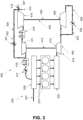
- Figure 3 illustrates the mixture supply system 400.
- the mixture supply system 400 has a valve train for periodically actuating an intake valve of the internal combustion engine 200, wherein a valve control time of the intake valve is controllable by the valve train (not shown).
- the mixture supply system 400 also has a charging system 410 that can be connected to the internal combustion engine 200.
- the charging system 410 can comprise a low-pressure turbocharger 430, wherein the low-pressure turbocharger 430 has a low-pressure compressor 419 and a low-pressure turbine 426 connected by means of a low-pressure turbocharger shaft 425.
- a gas mixer 427 can be connected to an inlet region of the low-pressure compressor 419, wherein the gas mixer 427 has a gas supply 414 and/or an air intake device 415.
- the charging system 410 may include a high-pressure turbocharger 440, wherein the high-pressure turbocharger 440 has a high-pressure compressor 411 and a high-pressure turbine 412 connected by a turbocharger shaft 413.
- the charging system 410 may include a line for connecting an outlet region of the low-pressure compressor 419 to an inlet region of the high-pressure compressor 411.
- An intercooler 418 may be arranged in the line.
- An inlet region of the high pressure turbine 412 may be connectable to an exhaust manifold 230.
- An outlet region of the high pressure turbine 412 may be connected to an inlet region of the low pressure turbine 426.
- An outlet region of the high-pressure compressor 411 can be connected to an intake manifold 220 of the internal combustion engine 200 by means of a connecting line.
- a charge air cooler 416 and/or a throttle valve 417 can be connected in the connecting line.
- the charging system 410 has a bypass 420.
- the bypass 420 can have a mixture return line 422 and an exhaust bypass line 423.
- a bypass valve 421, 424 is arranged in the bypass 420.
- a bypass valve 421, 424 is arranged in the mixture return line 422 and in the exhaust bypass line 423.
- the bypass 420 can connect the inlet region of the low-pressure turbine 426 of the low-pressure turbocharger 430 to the outlet region of the low-pressure turbine 426 of the low-pressure turbocharger 430 and the outlet region of the high-pressure compressor 411 of the high-pressure turbocharger 440 to the inlet region of the low-pressure compressor 419 of the low-pressure turbocharger 430.
- the internal combustion engine 200 can have at least one cylinder 210.
- the at least one cylinder can be connected to the intake manifold 220 and/or the exhaust manifold 230.
- the internal combustion engine 200 can have at least one intake valve, wherein the intake valve is arranged between the intake manifold 220 and the cylinder 210 (not shown).
- the intake valve can be periodically actuated by the valve train, wherein a valve control time of the intake valve can be controlled by the valve train.
- Gas can be supplied to the internal combustion engine 200 via the charging system 410 by means of the gas supply 414 connected to the gas mixer 427 and/or via a separate gas injection 201, in particular via the gas injection 201 connected to the intake manifold 220.
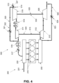
- Figure 4 illustrates the mixture supply system 500.
- the mixture supply system 500 has a valve train for periodically actuating an intake valve of the internal combustion engine 200, wherein a valve control time of the intake valve is controllable by the valve train (not shown).
- the mixture supply system 500 has a charging system 510 that can be connected to the internal combustion engine 200.
- the charging system 510 can comprise a low-pressure turbocharger 530, wherein the low-pressure turbocharger 530 has a low-pressure compressor 519 and a low-pressure turbine 526 connected by means of a low-pressure turbocharger shaft 525.
- a gas mixer 527 can be connected, wherein the gas mixer 527 has a gas supply 514 and/or an air intake device 515.
- the charging system 510 may include a high-pressure turbocharger 540, wherein the high-pressure turbocharger 540 has a high-pressure compressor 511 and a high-pressure turbine 512 connected by a turbocharger shaft 513.
- the charging system 510 may include a line for connecting an outlet region of the low-pressure compressor 519 to an inlet region of the high-pressure compressor 511.
- An intercooler 518 may be arranged in the line.
- An inlet region of the high pressure turbine 512 may be connectable to an exhaust manifold 230.
- An outlet region of the high pressure turbine 512 may be connected to an inlet region of the low pressure turbine 526.
- An outlet region of the high-pressure compressor 511 can be connected to an intake manifold 220 of the internal combustion engine 200 by means of a connecting line.
- a charge air cooler 516 and/or a throttle valve 517 can be connected in the connecting line.
- the charging system 510 has a bypass 520.
- the bypass 520 can have a mixture return line 522 and an exhaust bypass line 523.
- a bypass valve 521, 524 is arranged in the bypass 520.
- a bypass valve 521, 524 is arranged in the mixture return line 522 and in the exhaust bypass line 523.
- the bypass 520 can connect the inlet region of the high-pressure turbine 512 of the high-pressure turbocharger 540 to the outlet region of the low-pressure turbine 526 of the low-pressure turbocharger 530 and the outlet region of the high-pressure compressor 511 of the high-pressure turbocharger 540 to the inlet region of the low-pressure compressor 519 of the low-pressure turbocharger 530.
- the internal combustion engine 200 can have at least one cylinder 210.
- the at least one cylinder can be connected to the intake manifold 220 and/or the exhaust manifold 230.
- the internal combustion engine 200 can have at least one intake valve, wherein the intake valve is arranged between the intake manifold 220 and the cylinder 210 (not shown).
- the intake valve can be periodically actuated by the valve train, wherein a valve control time of the intake valve can be controlled by the valve train.
- a gas supply to the internal combustion engine 200 can be via the charging system 510 by means of the gas supply 514 connected to the gas mixer 527 and/or via a separate gas injection 201, in particular via the gas injection 201 connected to the inlet manifold 220.
- the mixture return line 122, 322, 422, 522 can connect the inlet region of the high-pressure turbine of the high-pressure turbocharger to the outlet region of the high-pressure turbine of the high-pressure turbocharger.
- the mixture return line 122, 322, 422, 522 can connect the inlet region of the low-pressure turbine of the low-pressure turbocharger to the outlet region of the low-pressure turbine of the low-pressure turbocharger.
- the throttle device in particular the throttle valve, can be arranged in the air intake device upstream of the gas mixer.
- the throttle device in particular the throttle valve, can be arranged, for example, in the line between the low-pressure compressor and the high-pressure compressor.
- the gas supply, and in particular the gas mixer can be arranged in the line between the low-pressure compressor and the high-pressure compressor.
Landscapes
- Engineering & Computer Science (AREA)
- Chemical & Material Sciences (AREA)
- Combustion & Propulsion (AREA)
- Mechanical Engineering (AREA)
- General Engineering & Computer Science (AREA)
- Physics & Mathematics (AREA)
- Thermal Sciences (AREA)
- Supercharger (AREA)
- Output Control And Ontrol Of Special Type Engine (AREA)
- Combined Controls Of Internal Combustion Engines (AREA)
- Combustion Methods Of Internal-Combustion Engines (AREA)
Description
- Die Erfindung betrifft ein Gemischzuführsystem für einen Verbrennungsmotor mit quantitativer Gemischregelung, und ein Verfahren zum Betreiben eines Gemischzuführsystems für einen Verbrennungsmotor mit quantitativer Gemischregelung.
- Verbrennungsmotoren, insbesondere Gas- und Zweistoffbetriebmotoren nach dem Otto-Kreisprozess arbeiten in einem definierten Bereich eines Luftüberschussverhältnisses. Die Betriebsgrenzen oder physikalischen Grenzen sind gegeben durch instabile Zündung bei hohen Luftüberschussverhältnissen und unkontrollierte Verbrennung durch Phänomene wie Selbstzündung und Klopfen bei niedrigen Luftüberschussverhältnissen. Darüber hinaus begrenzen die Emissionsvorschriften den Grenzwert für die maximalen Luftüberschussverhältnisse.
- Aus diesen Gründen bedarf es einer kontrollierten Einstellung des Luftüberschussverhältnisses in den Zylindern von Verbrennungsmotoren, sowohl während eines Intervalls, in dem eine Motorlast konstant ist, als auch bei Veränderungen, insbesondere abrupte Veränderungen, der Motorlast. Aus dem Stand der Technik ist es bekannt die Befüllung der Zylinder durch die Einstellung des Förderdrucks des Luftstroms (oder Gemischstroms) zu regeln. Eine Alternative hierzu ist es die Befüllung der Zylinder über das Einlassventil zu steuern.
- Die Einstellung des Förderdrucks erfolgt beispielsweise über eine Drosselklappe im Luftweg (oder Gemischweg), und durch Bereitstellung eines Aufladesystem, aufweisend einen Turbolader und eine oder mehrere Bypasskonfigurationen, d.h. über eine Regelung des Turboladerdrucks.
- Die Systeme basierend auf der Einstellung des Förderdrucks mittels Bypässen erzeugen Verluste, entweder durch Dissipation der Strömungsenergie in der Drosselklappe oder durch Verschwendung von Enthalpie auf einer Turbinenseite des Turboladers oder Rezirkulationsverluste auf einer Verdichterseite des Turboladers. Eine Alternative hierzu basiert auf der variablen Turbinengeometrie (VTG), die jedoch unter einem reduzierten Wirkungsgrad leidet, technisch komplex und kostenintensiv ist.
- Die Befüllung der Zylinder über das Einlassventil wird häufig gesteuert in dem der Schließzeitpunkt des Einlassventils variiert wird. Beispielsweise offenbart
WO 2008/000899 A1 eine Steueranordnung für ein Gaswechselventil in einem Kolbenmotor. Hierbei wird ein Hydraulikmedium zum Verzögern des Schließens des Ventils bereitgestellt. -
WO 2017/023333 A1 offenbart eine Verlängerung der Einlassventilöffnungsdauer bei einer Lasterhöhung, verbunden mit einem Schließen eines Bypassventils einer Aufladeeinrichtung. - Einige dieser Systeme können eine teilweise oder vollständige Variabilität der Zeitsteuerung des Einlassventils bieten, jedoch nicht mit der erforderlichen Schnelligkeit, wie sie für die Steuerung von Luftüberschussverhältnissen benötigt werden. Vorrichtungen zum Steuern des Schließzeitpunkts des Einlassventils haben daher den Nachteil, dass sie häufig langsam und träge sind oder dass schnell reagierende Systeme sehr aufwendig und kostenintensiv sind.
- Angesichts des vorstehend Erwähnten besteht ein Bedarf an einem verbesserten Gemischzuführsystem für einen Verbrennungsmotor.
- Diese Aufgabe wird zumindest teilweise gelöst durch ein Gemischzuführsystem für einen Verbrennungsmotor mit quantitativer Gemischregelung gemäß Anspruch 1. Ferner, wird die Aufgabe durch ein Verfahren zum Betreiben eines Gemischzuführsystems für einen Verbrennungsmotor mit quantitativer Gemischregelung gemäß Anspruch 14 gelöst. Weitere Ausführungsformen, Modifikationen und Verbesserungen ergeben sich anhand der folgenden Beschreibung und der beigefügten Ansprüche.
- Gemäß einer Ausführungsform wird ein Gemischzuführsystem für einen Verbrennungsmotor mit quantitativer Gemischregelung, insbesondere einen Gasmotor oder einen Zweistoffbetriebmotor, bereitgestellt. Das Gemischzuführsystem weist ein mit dem Verbrennungsmotor verbindbares Aufladesystem, aufweisend einen Bypass und ein im Bypass angeordnetes Bypassventil, auf. Ferner weist das Gemischzuführsystem einen Ventiltrieb zur periodischen Betätigung eines Einlassventils des Verbrennungsmotors auf, wobei eine Ventilsteuerzeit des Einlassventils durch den Ventiltrieb steuerbar ist. Das Gemischzuführsystem ist dazu eingerichtet, bei einem Anstieg einer Motorlast das Bypassventil mindestens teilweise zu schließen und die Ventilsteuerzeit für eine Verlängerung der Ventilöffnungsdauer zu verändern, und während und/oder nach Ablauf einer Ventiltrieblatenzzeit das Bypassventil mindestens teilweise zu öffnen; und/oder bei einer Verringerung der Motorlast das Bypassventil mindestens teilweise zu öffnen und die Ventilsteuerzeit für eine Verkürzung der Ventilöffnungsdauer zu verändern, und während und/oder nach Ablauf einer Ventiltrieblatenzzeit das Bypassventil mindestens teilweise zu schließen.
- Bei dem Anstieg der Motorlast wird durch eine Erhöhung der Brennstoffmenge zusätzliche thermische Energie für das Aufladesystem bereitgestellt. Bei einem unveränderten Öffnungsgrad des Bypassventils erhöht sich der Turboladerdruck oder der Förderdruck, trotzdem steigt jedoch die benötigte Menge Luft und/oder Gemisch stärker an als die vom Aufladesystem bereitgestellte. Um das Luftüberschussverhältnis innerhalb definierter Grenzen zu halten, kann daher das Gemischzuführsystem dazu eingerichtet sein bei dem Anstieg der Motorlast das Bypassventil teilweise zu schließen bzw. den Öffnungsgrad des Bypassventils zu verringern. Bei der Verringerung der Motorlast wird weniger thermische Energie für das Aufladesystem bereitgestellt. Bei einem unveränderten Öffnungsgrad des Bypassventils verringert sich der Turboladerdruck oder der Förderdruck, jedoch nicht in dem für die Einhaltung des Luftüberschussverhältnisses innerhalb definierter Grenzen benötigten Maß. Daher kann das Gemischzuführsystem dazu eingerichtet sein bei der Verringerung der Motorlast das Bypassventil teilweise zu öffnen bzw. den Öffnungsgrad des Bypassventils zu vergrößern.
- Die Ventiltrieblatenzzeit entspricht einem Zeitraum zwischen einer Veränderung der Ventilsteuerzeit und einem Zeitpunkt, an dem die Veränderung der Ventilsteuerzeit ihre volle Wirkung entfaltet. In anderen Worten kann der Ventiltrieb eine gewisse Trägheit aufweisen, d.h. nach einer Änderung der Ventilsteuerzeit des Einlassventils kann eine gewisse Zeit vergehen bis die Änderung der Ventilsteuerzeit in ihrer angestrebten Art eintritt. Durch eine Änderung der Motorlast, d.h. bei dem Anstieg oder der Verringerung der Motorlast, wird auch auf einer kurzen Zeitskala eine kontrollierte Einstellung des Luftüberschussverhältnisses in den Zylindern von Verbrennungsmotoren benötigt um innerhalb der Betriebsgrenzen oder physikalischen Grenzen zu operieren, und schädliche Auswirkungen, wie z.B. eine Erhöhung der NOx-Emission zu vermeiden. Die Trägheit von bekannten Ventiltrieben, ohne Bereitstellen von zusätzlichen Mitteln zum Einstellen des Luftüberschussverhältnisses, führt innerhalb der Ventiltrieblatenzzeit zu negativen Auswirkungen. Die Ventiltrieblatenzzeit dauert länger als ein einzelnes Arbeitsspiel. Eine typische Ventiltrieblatenzzeit kann dabei beispielsweise etwa 5-10 Arbeitszyklen betragen.
- Das in dem Bypass angeordnete Bypassventil ist vorteilhafterweise dazu eingerichtet schnell zu reagieren, insbesondere innerhalb eines Bruchteils einer Ventiltrieblatenzzeit. Durch teilweises oder vollständiges Schließen des Bypassventils bei dem Anstieg der Motorlast, kann das Luftüberschussverhältnis in den Zylindern während der Ventiltrieblatenzzeit innerhalb der Betriebsgrenzen eingestellt werden. Bei oder nach Ablauf der Ventiltrieblatenzzeit kann das Gemischzuführsystem dazu eingerichtet sein das Bypassventil mindestens teilweise zu öffnen. Vorteilhafterweise wird hierdurch ermöglicht bei oder nach Ablauf der Ventiltrieblatenzzeit das Luftüberschussverhältnis überwiegend oder sogar vollständig durch den Ventiltrieb zu kontrollieren.
- Das Gemischzuführsystem ist erfindungsgemäß dazu eingerichtet unmittelbar bei einem Anstieg der Motorlast das Bypassventil mindestens teilweise zu schließen und die Ventilsteuerzeit für eine Verlängerung der Ventilöffnungsdauer zu verändern (und entsprechend unmittelbar bei der Verringerung der Motorlast das Bypassventil mindestens teilweise zu öffnen und die Ventilsteuerzeit für eine Verkürzung der Ventilöffnungsdauer zu verändern). Bei einem Anstieg der Motorlast wird im Wesentlichen gleichzeitig das Bypassventil mindestens teilweise geschlossen und die Ventilsteuerzeit verändert; somit erfolgt eine Ansteuerung des Bypassventils und der Ventilsteuerzeit im Wesentlichen gleichzeitig (typischerweise innerhalb desselben Arbeitsspiels). Hierdurch wird ein Vorkompensieren des eher trägen Ventiltriebs (das einige Arbeitszyklen nach Ansteuerung benötigt bis die Änderung der Ventilsteuerzeit in ihrer angestrebten Art eintritt) durch das wesentlich schneller reagierende Bypassventil ermöglicht um innerhalb von Betriebsgrenzen zu operieren.
- In einer Ausführungsform ist das Gemischzuführsystem konfiguriert, bei dem Anstieg der Motorlast das Bypassventil in einer ersten Hälfte der Ventiltrieblatenzzeit mindestens teilweise zu schließen, und/oder bei der Verringerung der Motorlast das Bypassventil in der ersten Hälfte der Ventiltrieblatenzzeit mindestens teilweise zu öffnen.
- Durch teilweises Öffnen des Bypassventils bei der Verringerung der Motorlast, kann das Luftüberschussverhältnis in den Zylindern innerhalb der Betriebsgrenzen eingestellt werden, während der Ventiltrieblatenzzeit. Bei oder nach Ablauf der Ventiltrieblatenzzeit kann das Gemischzuführsystem dazu eingerichtet sein das Bypassventil mindestens teilweise zu schließen. Vorteilhafterweise wird hierdurch ermöglicht bei oder nach Ablauf der Ventiltrieblatenzzeit das Luftüberschussverhältnis überwiegend oder sogar vollständig durch den Ventiltrieb zu kontrollieren.
- Bei einer konstanten oder stationären Motorlast kann das Bypassventil geringfügig geöffnet sein oder fast geschlossen sein. In anderen Worten kann der Öffnungsgrad des Bypassventils bei einer konstanten Motorlast sehr gering sein. Hierdurch wird ermöglicht, dass bei einem Anstieg der Motorlast das Bypassventil weiter geschlossen werden kann, d.h. der Öffnungsgrad des Bypassventils verringert werden kann. Insbesondere ist bei einer konstanten Motorlast der Öffnungsgrad des Bypassventils gemäß Ausführungsformen der vorliegenden Offenbarung wesentlich geringer als bei Gemischzuführsystem, die ein Bypassventil aufweisen aber keine zusätzlichen Mittel zum Einstellen des Luftüberschussverhältnisses bereitstellen. In dem bei einer konstanten oder stationären Motorlast das Bypassventils geringfügig geöffnet sein oder fast geschlossen sein kann, wird ermöglicht dass Energieverluste, insbesondere durch Verschwendung von Enthalpie auf einer Turbinenseite des Turboladers oder Rezirkulationsverluste auf einer Verdichterseite des Turboladers, sehr geringfügig sind. Insbesondere bei großen, mittelschnelllaufenden Verbrennungsmotoren sind die Reduzierung von Energieverlusten, und damit ein geringerer Kraftstoffverbrauch, von erheblicher Bedeutung.
- Bei Verwendung von dem Gemischzuführsystem für den Verbrennungsmotor können veränderte Anforderungen an der Motorlast häufig auftreten. Beispielsweise kann auf ein Intervall konstanter oder stationärer Motorlast ein Anstieg der Motorlast und im Anschluss ein weiterer Anstieg oder eine Verringerung der Motorlast erwünscht sein. Gemäß einem allgemeinen Aspekt ist vorgesehen, dass das Gemischzuführsystem dazu eingerichtet ist, während und/oder nach Ablauf einer Ventiltrieblatenzzeit das Bypassventil mindestens teilweise derart zu öffnen bzw. den Öffnungsgrad des Bypassventils derart einzustellen, dass im Falle eines erneuten Anstiegs der Motorlast, der Bypass ausreichend geschlossen werden kann bzw. der Öffnungsgrad des Bypassventils ausreichend verringert werden kann. Gemäß einer Ausgestaltungsform sind ein erster Öffnungsgrad des Bypassventils vor dem Anstieg der Motorlast und ein zweiter Öffnungsgrad während und/oder nach Ablauf der Ventiltrieblatenzzeit im Wesentlichen gleich. In anderen Worten kann für eine stationäre Motorlast ein festlegbarer Öffnungsgrad vorgesehen sein, wobei während und/oder nach Ablauf der Ventiltrieblatenzzeit das Gemischzuführsystem dazu eingerichtet sein kann den festlegbaren Öffnungsgrad einzustellen.
- Gemäß einem allgemeinen Aspekt kann das Gemischzuführsystem vorgesehen sein bei einem abruptem Anstieg der Motorlast das Bypassventil mindestens teilweise zu schließen und die Ventilsteuerzeit für die Verlängerung der Ventilöffnungsdauer zu verändern, und während und/oder nach Ablauf der Ventiltrieblatenzzeit das Bypassventil mindestens teilweise zu öffnen. Bei langsameren Änderungen der Motorlast, beispielsweise Änderungen von Umgebungsbedingungen wie eine Temperatur und/oder ein Druck und/oder eine Gasqualität, kann vorgesehen sein den Öffnungsgrad des Bypassventils unverändert zu lassen. Bei langsameren Änderungen der Motorlast kann das Gemischzuführsystem eingerichtet sein die Ventilsteuerzeit für die Verlängerung der Ventilöffnungsdauer zu verändern.
- Gemäß einer Ausführungsform weist das Gemischzuführsystem eine Kontrolleinheit auf. Die Kontrolleinheit kann eingerichtet sein den Öffnungsgrad des Bypassventils einzustellen und/oder die Ventilsteuerzeit des Einlassventils durch den Ventiltrieb zu verändern. Insbesondere kann die Kontrolleinheit eingerichtet sein, bei dem Anstieg der Motorlast und/oder bei der Verringerung der Motorlast den Öffnungsgrad des Bypassventils einzustellen und die Ventilsteuerzeit des Einlassventils durch den Ventiltrieb zu verändern.
- Die Kontrolleinheit kann ferner dazu eingerichtet sein, während und/oder nach Ablauf der Ventiltrieblatenzzeit, in Abhängigkeit eines Parameters den Öffnungsgrad des Bypassventils einzustellen. Der Parameter kann dazu geeignet sein zu bestimmen ob die Ventiltrieblatenzzeit abgelaufen ist. Der Parameter kann dazu geeignet sein eine mittels des Bypasses benötigte Menge Luft und/oder Gemisch zu bestimmen bzw. eine mittels des Bypasses benötigte Absenkung der Menge Luft und/oder Gemisch zu bestimmen. Beispielsweise kann der Parameter ein Brennstoff-Luft-Verhältnis oder ein aus Messgrößen abgeschätztes Brennstoff-Luft-Verhältnis in einer Brennkammer des Verbrennungsmotors sein. In einer anderen beispielshaften Ausführungsform ist der Parameter ein Ladedruck. Der Ladedruck steht dabei stellvertretend für die Luftmenge im Zylinder.
- Das Bypassventil kann ein Drosselventil sein. Ferner kann das Bypassventil schrittweise oder stufenlos einstellbar sein. Die Kontrolleinheit kann ferner dazu sein eingerichtet, während und/oder nach Ablauf der Ventiltrieblatenzzeit, den Öffnungsgrad des Bypassventils schrittweise oder stufenlos einzustellen. Während der Ventiltrieblatenzzeit kann die Veränderung der Ventilsteuerzeit schrittweise oder stufenlos ihre Wirkung entfalten, bis am Ende des Zeitraums die Veränderung der Ventilsteuerzeit ihre volle Wirkung entfaltet. Die Kontrolleinheit kann ferner dazu sein eingerichtet, während und/oder nach Ablauf der Ventiltrieblatenzzeit, den Öffnungsgrad des Bypassventils in Abhängigkeit des Parameters schrittweise oder stufenlos einzustellen.
- Das Aufladesystem kann einen oder mehrere Turbolader aufweisen. Jeder Turbolader kann einen Verdichter und eine mittels einer Turboladerwelle mit dem Verdichter verbundene Turbine aufweisen. Das Aufladesystem kann mit einem Einlasssammler und/oder einer Abgassammelleitung des Verbrennungsmotors mit quantitativer Gemischregelung verbindbar sein. Insbesondere können ein Auslassbereich des Verdichters mit dem Einlasssammler und ein Einlassbereich der Turbine mit der Abgassammelleitung verbindbar sein. In einer mit dem Auslassbereich des Verdichters verbundenen und mit dem Einlasssammler verbindbaren Anschlussleitung kann ein Ladeluftkühler und/oder eine Drosseleinrichtung, beispielsweise eine Drosselklappe, angeordnet sein. An einem Einlassbereich des Verdichters kann eine Luftansaugvorrichtung angeschlossen sein und/oder ein Gasmischer angeschlossen sein, wobei der Gasmischer die Luftansaugvorrichtung und eine Gaszuführung aufweist. Der Bypass kann dabei den Auslassbereich des Verdichters mit dem Einlassbereich des Verdichters verbinden und/oder der Bypass kann dabei den Einlassbereich der Turbine mit dem Auslassbereich der Turbine verbinden. Der "und" Fall ist dahingehend zu verstehen, dass der Bypass zwei separate Leitungen aufweist, eine Luftrückführleitung oder Gemischrückführleitung und eine Abgasbypassleitung. Sowohl die Luftrückführleitung oder Gemischrückführleitung als auch die Abgasbypassleitung weisen bevorzugt jeweils ein Bypassventil auf.
- Das Aufladesystem kann ferner mindestens zwei Turbolader aufweisen, wobei der Bypass einen Einlassbereich einer Turbine des ersten Turboladers mit einem Auslassbereich einer Turbine des zweiten Turboladers und/oder einen Auslassbereich eines Verdichters des ersten Turboladers mit einem Einlassbereich eines Verdichters des zweiten Turboladers verbinden kann.
- Beispielsweise kann das Aufladesystem einen Niederduck-Turbolader und einen Hochdruck-Turbolader aufweisen. An einem Einlassbereich des Niederdruck-Verdichters kann die Luftansaugvorrichtung angeschlossen sein und/oder der Gasmischer angeschlossen sein, wobei der Gasmischer die Luftansaugvorrichtung und die Gaszuführung aufweist. Das Aufladesystem kann eine Leitung zum Verbinden eines Auslassbereichs des Niederduck-Verdichters mit einem Einlassbereich des Hochdruck-Verdichters aufweisen. In der Leitung kann ein Zwischenkühler angeordnet sein.
- Der Ventiltrieb kann zum zeitlichen Verschieben der Betätigung des Einlassventils eingerichtet sein. Somit kann eine zeitliche Verschiebung des Ventilhubs erfolgen, insbesondere zur Steuerung der Zylinderladung. Das zeitliche Verschieben der Schließbewegung des Einlassventils kann stufenlos einstellbar sein. Hierdurch wird eine genaue Einstellung der Befüllung des Zylinders, insbesondere des Zylinderdrucks, ermöglicht. Dadurch können die einzelnen Zylinder auch einander gleichgestellt werden.
- Der Ventiltrieb kann zum zeitlichen Verschieben einer Schließbewegung des Einlassventils eingerichtet sein. Das zeitliche Verschieben der Schließbewegung des Einlassventils kann stufenlos einstellbar sein. Hierdurch wird eine genaue Einstellung der Befüllung des Zylinders, insbesondere des Zylinderdrucks, ermöglicht.
- Gemäß einer Ausführungsform weist der Ventiltrieb ferner ein Verzögerungselement zum Verschieben der Schließbewegung des Einlassventils auf. Insbesondere kann das Verzögerungselement ein mechanisches oder ein hydraulisches Verzögerungselement sein. Das Verzögerungselement kann eine Hydraulikkammer zum Verschieben der Schließbewegung des Einlassventils mittels eines Hydraulikmediums aufweisen. Der Ventiltrieb kann einen Einlassventil-Betätigungsmechanismus aufweisen, wobei der Einlassventil-Betätigungsmechanismus mit dem Verzögerungselement in Kontakt zum zeitlichen Verschieben einer Schließbewegung des Einlassventils eingerichtet sein kann. Beispielsweise kann der Einlassventil-Betätigungsmechanismus mindestens eines ausgewählt von einem Kipphebel, einem Schlepphebel, einer Stößelstange und einer Ventilbrücke aufweisen, wobei das Verzögerungselement in Kontakt mit dem Kipphebel oder dem Schlepphebel oder der Stößelstange oder der Ventilbrücke sein kann.
- Ferner kann alternativ oder ergänzend zur zeitlichen Verschiebung der Schliessbewegung des Einlassventils oder der zeitlichen Verschiebung des Ventilhubs auch der Ventilhub zur Steuerung der Zylinderladung angepasst werden.. Somit kann der Ventiltrieb zum Anpassen des Ventilhubs eingerichtet sein.
- Die vorangehend beschriebenen Ausgestaltungformen, bezogen auf Komponenten des Einlassventils und/oder Komponenten des Ventiltriebs sind entsprechend auch für ein Auslassventil des Verbrennungsmotors übertragbar.
- Der Verbrennungsmotor mit quantitativer Gemischregelung kann ein stationärer Verbrennungsmotor oder ein Antriebsmotor sein. Der Verbrennungsmotor kann ein Ottomotor sein, insbesondere kann der Verbrennungsmotor ein Viertaktmotor sein. Der Verbrennungsmotor mit quantitativer Gemischregelung kann ein Gasmotor oder ein Zweistoffbetriebmotor sein. Eine Gaszuführung des Gasmotors oder des Zweistoffbetriebmotors kann über das Aufladesystem mittels der an dem Gasmischer angeschlossenen Gaszuführung erfolgen und/oder über eine separate Gaseinspritzung, insbesondere über der an dem Einlasssammler angeschlossene Gaseinspritzung. Die Gaseinspritzung kann auch über einen zwischen dem Einlasssammler und dem Zylinder angeordneten Ansaugkanal erfolgen (Saugrohreinspritzung).
- Gemäß einer Ausführungsform wird ein Verbrennungsmotor mit quantitativer Gemischregelung, insbesondere ein Gasmotor oder ein Zweistoffbetriebmotor, bereitgestellt. Der Verbrennungsmotor weist ein Gemischzuführsystem nach einem der hierin beschriebenen Ausführungsformen auf. Der Verbrennungsmotor kann dabei eine Vielzahl Zylinder und einen Ventiltrieb zur periodischen Betätigung eines oder mehrerer Einlassventile für jeden Zylinder des Verbrennungsmotors aufweisen.
- Die hierin beschriebenen Ausführungsformen können mit geringfügigen konstruktiven Aufwand realisiert werden, insbesondere für Gemischzuführsysteme, die bereits Ventiltriebe aufweisen bei denen eine Ventilsteuerzeit des Einlassventils durch den Ventiltrieb steuerbar ist. Dadurch lässt sich auf einfache und kostengünstige Weise ein verbessertes Gemischzuführsystem erzielen.
- Gemäß einer Ausführungsform wird ein Verfahren zum Betreiben eines Gemischzuführsystems für einen Verbrennungsmotor mit quantitativer Gemischregelung bereitgestellt. Insbesondere kann der Verbrennungsmotor mit quantitativer Gemischregelung ein Gasmotor oder ein Zweistoffbetriebmotor sein. Das Gemischzuführsystem weist ein mit dem Verbrennungsmotor verbindbares Aufladesystem, aufweisend einen Bypass und ein im Bypass angeordnetes Bypassventil, auf. Ferner weist das Gemischzuführsystem einen Ventiltrieb zur periodischen Betätigung eines Einlassventils des Verbrennungsmotors auf, wobei eine Ventilsteuerzeit des Einlassventils durch den Ventiltrieb steuerbar ist. Insbesondere kann der Verbrennungsmotor das Gemischzuführsystem gemäß einem der hierin beschriebenen Ausführungsformen aufweisen.
- Das Verfahren weist auf:
- A) Bei dem Anstieg einer Motorlast:
- A1) Teilweise Schließen des Bypassventils und Verschieben der Ventilsteuerzeit, um die Ventilöffnungsdauer zu verlängern; und
- A2) Teilweise Öffnen des Bypassventils während und/oder nach Ablauf einer Ventiltrieblatenzzeit; und/oder
- B) Bei der Verringerung der Motorlast:
- B1) Teilweise Öffnen des Bypassventils und Verschieben der Ventilsteuerzeit, um die Ventilöffnungsdauer zu verkürzen; und
- B2) Teilweise Schließen des Bypassventils während und/oder nach Ablauf einer Ventiltrieblatenzzeit.
- Schritt A2) erfolgt nach Schritt A1). Schritt B2) erfolgt nach Schritt B1). Die Schritte A2) und/oder B2) können in Abhängigkeit des Brennstoff-Luft-Verhältnisses eingestellt werden.
- Nachfolgend wird die Erfindung anhand von Ausführungsformen näher erläutert, ohne dass diese den durch die Ansprüche definierten Schutzbereich einschränken sollen.
- Die beiliegenden Zeichnungen veranschaulichen Ausführungsformen und dienen zusammen mit der Beschreibung der Erläuterung der Prinzipien der Erfindung. Die Elemente der Zeichnungen sind relativ zueinander und nicht notwendigerweise maßstabsgetreu. Gleiche Bezugszeichen bezeichnen entsprechend ähnliche Teile.
- Die Figuren zeigen:
-
Figur 1 zeigt einen Teil eines erfindungsgemäßen Gemischzuführsystems gemäß einer Ausführungsform. -
Figur 2 zeigt einen Teil eines erfindungsgemäßen Gemischzuführsystems gemäß einer Ausführungsform. -
Figur 3 zeigt einen Teil eines erfindungsgemäßen Gemischzuführsystems gemäß einer Ausführungsform. -
Figur 4 zeigt einen Teil eines erfindungsgemäßen Gemischzuführsystems gemäß einer Ausführungsform. - Die
Figuren 1 bis 4 zeigen - in schematischer Darstellung - Teile von verschiedenen Ausführungsformen eines erfindungsgemäßen Gemischzuführsystems 100, 300, 400, 500 für einen Verbrennungsmotor 200 mit quantitativer Gemischregelung, insbesondere einen Gasmotor oder einen Zweistoffbetriebmotor. - Die gestrichelten Pfeile in den
Figuren 1 bis 4 deuten die Zuordnung der Bezugszeichen zu den Merkmalen an. Die fetten und als durchgezogene Linien gezeichneten Pfeile in denFiguren 1 bis 4 deuten eine Flussrichtung an. - Die Figuren illustrieren Teile des erfindungsgemäßen Gemischzuführsystems 100, 300, 400, 500, insbesondere ein Aufladesystem 110, 310, 410, 510 und zeigen beispielhaft Teile des mit dem Gemischzuführsystems 100, 300, 400, 500 verbindbaren Verbrennungsmotor.
-
Figur 1 illustriert das Gemischzuführsystem 100. Das Gemischzuführsystem 100 weist einen Ventiltrieb zur periodischen Betätigung eines Einlassventils des Verbrennungsmotors 200 auf, wobei eine Ventilsteuerzeit des Einlassventils durch den Ventiltrieb steuerbar ist (nicht dargestellt). - Ferner weist das Gemischzuführsystem 100 ein mit dem Verbrennungsmotor 200 verbindbares Aufladesystem 110 auf. Das Aufladesystem kann einen Turbolader 140 umfassen, wobei der Turbolader einen Verdichter 111 und eine mittels einer Turboladerwelle 113 verbundene Turbine 112 aufweist. Ein Einlassbereich der Turbine 112 kann verbindbar mit einer Abgassammelleitung 230 sein. Ein Auslassbereich des Verdichters 111 kann mittels einer Anschlussleitung mit einem Einlasssammler 220 des Verbrennungsmotors 200 verbindbar sein. In der Anschlussleitung kann ein Ladeluftkühler 116 und/oder eine Drosselklappe 117 angeschlossen sein. An einem Einlassbereich des Verdichters 111 kann ein Gasmischer 127 angeschlossen sein, wobei der Gasmischer 127 eine Gaszuführung 114 und/oder eine Luftansaugvorrichtung 115 aufweist.
- Das Aufladesystem 110 weist einen Bypass 120 auf. Der Bypass 120 kann eine Gemischrückführleitung 122 und eine Abgasbypassleitung 123 aufweisen. Im Bypass ist ein Bypassventil 121, 124 angeordnet. Insbesondere sind in der Gemischrückführleitung 122 und in der Abgasbypassleitung 123 jeweils ein Bypassventil 121, 124 angeordnet. Der Bypass 120 kann den Einlassbereich der Turbine 112 des Turboladers 140 mit dem Auslassbereich der Turbine 112 des Turboladers 140 und den Auslassbereich des Verdichters 111 des Turboladers 140 mit dem Einlassbereich des Verdichters 111 des Turboladers 140 verbinden.
- Der Verbrennungsmotor 200 kann mindestens einen Zylinder 210 aufweisen. Der mindestens eine Zylinder kann mit dem Einlasssammler 220 und/oder der Abgassammelleitung 230 verbunden sein. Der Verbrennungsmotor 200 kann mindestens ein Einlassventil aufweisen, wobei das Einlassventil zwischen dem Einlasssammler 220 und dem Zylinder 210 angeordnet sein kann (nicht dargestellt). Das Einlassventil kann durch den Ventiltrieb periodisch betätigt werden, wobei eine Ventilsteuerzeit des Einlassventils durch den Ventiltrieb steuerbar ist. Eine Gaszuführung des Verbrennungsmotors 200 kann über das Aufladesystem 110 mittels der an dem Gasmischer 127 angeschlossenen Gaszuführung 114 erfolgen und/oder über eine separate Gaseinspritzung 201, insbesondere über der an dem Einlasssammler 220 angeschlossenen Gaseinspritzung 201.
-
Figur 2 illustriert das Gemischzuführsystem 300. Das Gemischzuführsystem 300 weist einen Ventiltrieb zur periodischen Betätigung eines Einlassventils des Verbrennungsmotors 200 auf, wobei eine Ventilsteuerzeit des Einlassventils durch den Ventiltrieb steuerbar ist (nicht dargestellt). - Ferner weist das Gemischzuführsystem 300 ein mit dem Verbrennungsmotor 200 verbindbares Aufladesystem 310 auf. Das Aufladesystem 310 kann einen Niederdruck-Turbolader 330 umfassen, wobei der Niederdruck-Turbolader 330 einen Niederdruck-Verdichter 319 und eine mittels einer Niederdruck-Turboladerwelle 325 verbundene Niederdruck-Turbine 326 aufweist. An einem Einlassbereich des Niederdruck-Verdichters 319 kann ein Gasmischer 327 angeschlossen sein, wobei der Gasmischer 327 eine Gaszuführung 314 und/oder eine Luftansaugvorrichtung 315 aufweist.
- Das Aufladesystem 310 kann einen Hochdruck-Turbolader 340 umfassen, wobei der Hochdruck-Turbolader 340 einen Hochdruck-Verdichter 311 und eine mittels einer Turboladerwelle 313 verbundene Hochdruck-Turbine 312 aufweist.
- Das Aufladesystem 310 kann eine Leitung zum Verbinden eines Auslassbereichs des Niederduck-Verdichters 319 mit einem Einlassbereich des Hochdruck-Verdichters 311 aufweisen. In der Leitung kann ein Zwischenkühler 318 angeordnet sein.
- Ein Einlassbereich der Hochdruck-Turbine 312 kann verbindbar mit einer Abgassammelleitung 230 sein. Ein Auslassbereich der Hochdruck-Turbine 312 kann mit einem Einlassbereich der Niederdruck-Turbine 326 verbunden sein.
- Ein Auslassbereich des Hochdruck-Verdichters 311 kann mittels einer Anschlussleitung mit einem Einlasssammler 220 des Verbrennungsmotors 200 verbindbar sein. In der Anschlussleitung kann ein Ladeluftkühler 316 und/oder eine Drosselklappe 317 angeschlossen sein.
- Das Aufladesystem 310 weist einen Bypass 320 auf. Der Bypass 320 kann eine Gemischrückführleitung 322 und eine Abgasbypassleitung 323 aufweisen. Im Bypass ist ein Bypassventil 321, 324 angeordnet. Insbesondere sind in der Gemischrückführleitung 322 und in der Abgasbypassleitung 323 jeweils ein Bypassventil 321, 324 angeordnet. Der Bypass 320 kann den Einlassbereich der Hochdruck-Turbine 312 des Hochdruck-Turboladers 340 mit dem Auslassbereich der Hochdruck-Turbine 312 des Hochdruck-Turboladers 340 und den Auslassbereich des Hochdruck-Verdichters 311 des Hochdruck-Turboladers 340 mit dem Einlassbereich des Niederdruck-Verdichters 319 des Niederdruck-Turboladers 330 verbinden.
- Der Verbrennungsmotor 200 kann mindestens einen Zylinder 210 aufweisen. Der mindestens eine Zylinder kann mit dem Einlasssammler 220 und/oder der Abgassammelleitung 230 verbunden sein. Der Verbrennungsmotor 200 kann mindestens ein Einlassventil aufweisen, wobei das Einlassventil zwischen dem Einlasssammler 220 und dem Zylinder 210 angeordnet ist (nicht dargestellt). Das Einlassventil kann durch den Ventiltrieb periodisch betätigt werden, wobei eine Ventilsteuerzeit des Einlassventils durch den Ventiltrieb steuerbar ist. Eine Gaszuführung des Verbrennungsmotors 200 kann über das Aufladesystem 310 mittels der an dem Gasmischer 327 angeschlossenen Gaszuführung 314 erfolgen und/oder über eine separate Gaseinspritzung 201, insbesondere über der an dem Einlasssammler 220 angeschlossenen Gaseinspritzung 201.
-
Figur 3 illustriert das Gemischzuführsystem 400. Das Gemischzuführsystem 400 weist einen Ventiltrieb zur periodischen Betätigung eines Einlassventils des Verbrennungsmotors 200 auf, wobei eine Ventilsteuerzeit des Einlassventils durch den Ventiltrieb steuerbar ist (nicht dargestellt). - Ferner weist das Gemischzuführsystem 400 ein mit dem Verbrennungsmotor 200 verbindbares Aufladesystem 410 auf. Das Aufladesystem 410 kann einen Niederdruck-Turbolader 430 umfassen, wobei der Niederdruck-Turbolader 430 einen Niederdruck-Verdichter 419 und eine mittels einer Niederdruck-Turboladerwelle 425 verbundene Niederdruck-Turbine 426 aufweist. An einem Einlassbereich des Niederdruck-Verdichters 419 kann ein Gasmischer 427 angeschlossen sein, wobei der Gasmischer 427 eine Gaszuführung 414 und/oder eine Luftansaugvorrichtung 415 aufweist.
- Das Aufladesystem 410 kann einen Hochdruck-Turbolader 440 umfassen, wobei der Hochdruck-Turbolader 440 einen Hochdruck-Verdichter 411 und eine mittels einer Turboladerwelle 413 verbundene Hochdruck-Turbine 412 aufweist.
- Das Aufladesystem 410 kann eine Leitung zum Verbinden eines Auslassbereichs des Niederduck-Verdichters 419 mit einem Einlassbereich des Hochdruck-Verdichters 411 aufweisen. In der Leitung kann ein Zwischenkühler 418 angeordnet sein.
- Ein Einlassbereich der Hochdruck-Turbine 412 kann verbindbar mit einer Abgassammelleitung 230 sein. Ein Auslassbereich der Hochdruck-Turbine 412 kann mit einem Einlassbereich der Niederdruck-Turbine 426 verbunden sein.
- Ein Auslassbereich des Hochdruck-Verdichters 411 kann mittels einer Anschlussleitung mit einem Einlasssammler 220 des Verbrennungsmotors 200 verbindbar sein. In der Anschlussleitung kann ein Ladeluftkühler 416 und/oder eine Drosselklappe 417 angeschlossen sein.
- Das Aufladesystem 410 weist einen Bypass 420 auf. Der Bypass 420 kann eine Gemischrückführleitung 422 und eine Abgasbypassleitung 423 aufweisen. Im Bypass 420 ist ein Bypassventil 421, 424 angeordnet. Insbesondere sind in der Gemischrückführleitung 422 und in der Abgasbypassleitung 423 jeweils ein Bypassventil 421, 424 angeordnet. Der Bypass 420 kann den Einlassbereich der Niederdruck-Turbine 426 des Niederdruck-Turboladers 430 mit dem Auslassbereich der Niederdruck-Turbine 426 des Niederdruck-Turboladers 430 und den Auslassbereich des Hochdruck-Verdichters 411 des Hochdruck-Turboladers 440 mit dem Einlassbereich des Niederdruck-Verdichters 419 des Niederdruck-Turboladers 430 verbinden.
- Der Verbrennungsmotor 200 kann mindestens einen Zylinder 210 aufweisen. Der mindestens eine Zylinder kann mit dem Einlasssammler 220 und/oder der Abgassammelleitung 230 verbunden sein. Der Verbrennungsmotor 200 kann mindestens ein Einlassventil aufweisen, wobei das Einlassventil zwischen dem Einlasssammler 220 und dem Zylinder 210 angeordnet ist (nicht dargestellt). Das Einlassventil kann durch den Ventiltrieb periodisch betätigt werden, wobei eine Ventilsteuerzeit des Einlassventils durch den Ventiltrieb steuerbar ist. Eine Gaszuführung des Verbrennungsmotors 200 kann über das Aufladesystem 410 mittels der an dem Gasmischer 427 angeschlossenen Gaszuführung 414 erfolgen und/oder über eine separate Gaseinspritzung 201, insbesondere über der an dem Einlasssammler 220 angeschlossenen Gaseinspritzung 201.
-
Figur 4 illustriert das Gemischzuführsystem 500. Das Gemischzuführsystem 500 weist einen Ventiltrieb zur periodischen Betätigung eines Einlassventils des Verbrennungsmotors 200 auf, wobei eine Ventilsteuerzeit des Einlassventils durch den Ventiltrieb steuerbar ist (nicht dargestellt). - Ferner weist das Gemischzuführsystem 500 ein mit dem Verbrennungsmotor 200 verbindbares Aufladesystem 510 auf. Das Aufladesystem 510 kann einen Niederdruck-Turbolader 530 umfassen, wobei der Niederdruck-Turbolader 530 einen Niederdruck-Verdichter 519 und eine mittels einer Niederdruck-Turboladerwelle 525 verbundene Niederdruck-Turbine 526 aufweist. An einem Einlassbereich des Niederdruck-Verdichters 519 kann ein Gasmischer 527 angeschlossen sein, wobei der Gasmischer 527 eine Gaszuführung 514 und/oder eine Luftansaugvorrichtung 515 aufweist.
- Das Aufladesystem 510 kann einen Hochdruck-Turbolader 540 umfassen, wobei der Hochdruck-Turbolader 540 einen Hochdruck-Verdichter 511 und eine mittels einer Turboladerwelle 513 verbundene Hochdruck-Turbine 512 aufweist.
- Das Aufladesystem 510 kann eine Leitung zum Verbinden eines Auslassbereichs des Niederduck-Verdichters 519 mit einem Einlassbereich des Hochdruck-Verdichters 511 aufweisen. In der Leitung kann ein Zwischenkühler 518 angeordnet sein.
- Ein Einlassbereich der Hochdruck-Turbine 512 kann verbindbar mit einer Abgassammelleitung 230 sein. Ein Auslassbereich der Hochdruck-Turbine 512 kann mit einem Einlassbereich der Niederdruck-Turbine 526 verbunden sein.
- Ein Auslassbereich des Hochdruck-Verdichters 511 kann mittels einer Anschlussleitung mit einem Einlasssammler 220 des Verbrennungsmotors 200 verbindbar sein. In der Anschlussleitung kann ein Ladeluftkühler 516 und/oder eine Drosselklappe 517 angeschlossen sein.
- Das Aufladesystem 510 weist einen Bypass 520 auf. Der Bypass 520 kann eine Gemischrückführleitung 522 und eine Abgasbypassleitung 523 aufweisen. Im Bypass 520 ist ein Bypassventil 521, 524 angeordnet. Insbesondere sind in der Gemischrückführleitung 522 und in der Abgasbypassleitung 523 jeweils ein Bypassventil 521, 524 angeordnet. Der Bypass 520 kann den Einlassbereich der Hochdruck-Turbine 512 des Hochdruck-Turboladers 540 mit dem Auslassbereich der Niederdruck-Turbine 526 des Niederdruck-Turboladers 530 und den Auslassbereich des Hochdruck-Verdichters 511 des Hochdruck-Turboladers 540 mit dem Einlassbereich des Niederdruck-Verdichters 519 des Niederdruck-Turboladers 530 verbinden.
- Der Verbrennungsmotor 200 kann mindestens einen Zylinder 210 aufweisen. Der mindestens eine Zylinder kann mit dem Einlasssammler 220 und/oder der Abgassammelleitung 230 verbunden sein. Der Verbrennungsmotor 200 kann mindestens ein Einlassventil aufweisen, wobei das Einlassventil zwischen dem Einlasssammler 220 und dem Zylinder 210 angeordnet ist (nicht dargestellt). Das Einlassventil kann durch den Ventiltrieb periodisch betätigt werden, wobei eine Ventilsteuerzeit des Einlassventils durch den Ventiltrieb steuerbar ist. Eine Gaszuführung des Verbrennungsmotors 200 kann über das Aufladesystem 510 mittels der an dem Gasmischer 527 angeschlossenen Gaszuführung 514 erfolgen und/oder über eine separate Gaseinspritzung 201, insbesondere über der an dem Einlasssammler 220 angeschlossenen Gaseinspritzung 201.
- Wenngleich hierin spezifische Ausführungsformen dargestellt und beschrieben worden sind, liegt es im Rahmen der vorliegenden Erfindung, die gezeigten Ausführungsformen geeignet zu kombinieren oder zu modifizieren, ohne vom Schutzbereich der vorliegenden Erfindung abzuweichen wie er in den beigefügten Ansprüchen definiert ist. Beispielsweise kann die Gemischrückführleitung 122, 322, 422, 522 den Einlassbereich der Hochdruck-Turbine des Hochdruck-Turboladers mit dem Auslassbereich der Hochdruck-Turbine des Hochdruck-Turboladers verbinden. Beispielsweise kann die Gemischrückführleitung 122, 322, 422, 522 den Einlassbereich der Niederdruck-Turbine des Niederdruck-Turboladers mit dem Auslassbereich der Niederdruck-Turbine des Niederdruck-Turboladers verbinden. Beispielsweise kann die Drosseleinrichtung, insbesondere die Drosselklappe, in der Luftansaugvorrichtung vor dem Gasmischer angeordnet sein. Alternativ kann die Drosseleinrichtung, insbesondere die Drosselklappe, beispielsweise in der Leitung zwischen Niederdruck-Verdichter und Hochdruck-Verdichter angeordnet sein. Beispielsweise kann die Gaszuführung, und insbesondere der Gasmischer, in der Leitung zwischen Niederdruck-Verdichter und Hochdruck-Verdichter angeordnet sein.
-
- 100, 300, 400, 500 Gemischzuführsystem
- 110, 310, 410, 510 Aufladesystem
- 140, 340, 440, 540 Turbolader / Hochdruck-Turbolader
- 111 Verdichter
- 112 Turbine
- 113, 313, 413, 513 Turboladerwelle
- 114, 314, 414, 514 Gaszuführung
- 115, 315, 415, 515 Luftansaugvorrichtung
- 116, 316, 416, 516 Ladeluftkühler
- 117, 317, 417, 517 Drosselklappe
- 127, 327, 427, 527 Gasmischer
- 120, 320, 420, 520 Bypass
- 121, 124, 321, 324, 421, 424, 521, 524 Bypassventil;
- 122, 322, 422, 522 Gemischrückführleitung
- 123, 323, 423, 523 Abgasbypassleitung
- 200 Verbrennungsmotor
- 201 Gaseinspritzung
- 210 Zylinder
- 220 Einlasssammler
- 230 Abgassammelleitung
- 330, 430, 530 Turbolader / Niederdruck-Turbolader
- 311, 411, 511 Hochdruck-Verdichter
- 312, 412, 512 Hochdruck-Turbine
- 318, 418, 518 Zwischenkühler
- 319, 419, 519 Niederdruck-Verdichter
- 325, 425, 525 Niederdruck-Turboladerwelle
- 326, 426, 526 Niederdruck-Turbine
Claims (15)
- Gemischzuführsystem (100, 300, 400, 500) für einen Verbrennungsmotor (200) mit quantitativer Gemischregelung, insbesondere einen Gasmotor oder einen Zweistoffbetriebmotor, das Gemischzuführsystem (100, 300, 400, 500) aufweisend:ein mit dem Verbrennungsmotor (200) verbindbares Aufladesystem (110, 310, 410, 510), aufweisend einen Bypass (120, 320, 420, 520) und ein im Bypass (120, 320, 420, 520) angeordnetes Bypassventil (121, 124, 321, 324, 421, 424, 521, 524);einen Ventiltrieb zur periodischen Betätigung eines Einlassventils des Verbrennungsmotors (200), wobei eine Ventilsteuerzeit des Einlassventils durch den Ventiltrieb steuerbar ist;wobei das Gemischzuführsystem (100, 300, 400, 500) dazu eingerichtet ist,- bei einem Anstieg einer Motorlast das Bypassventil (121, 124, 321, 324, 421, 424, 521, 524) mindestens teilweise zu schließen und die Ventilsteuerzeit für eine Verlängerung der Ventilöffnungsdauer zu verändern, und während und/oder nach Ablauf einer Ventiltrieblatenzzeit das Bypassventil (121, 124, 321, 324, 421, 424, 521, 524) mindestens teilweise zu öffnen; und/oder- bei einer Verringerung der Motorlast das Bypassventil (121, 124, 321, 324, 421, 424, 521, 524) mindestens teilweise zu öffnen und die Ventilsteuerzeit für eine Verkürzung der Ventilöffnungsdauer zu verändern, und während und/oder nach Ablauf einer Ventiltrieblatenzzeit das Bypassventil (121, 124, 321, 324, 421, 424, 521, 524) mindestens teilweise zu schließen.
- Gemischzuführsystem nach Anspruch 1, ferner aufweisend eine Kontrolleinheit, die eingerichtet ist, bei dem Anstieg der Motorlast und/oder bei der Verringerung der Motorlast einen Öffnungsgrad des Bypassventils (121, 124, 321, 324, 421, 424, 521, 524) einzustellen und die Ventilsteuerzeit des Einlassventils durch den Ventiltrieb zu verändern.
- Gemischzuführsystem nach Anspruch 2, wobei die Kontrolleinheit eingerichtet ist, während und/oder nach Ablauf der Ventiltrieblatenzzeit, in Abhängigkeit eines Brennstoff-Luft-Verhältnisses in einer Brennkammer des Verbrennungsmotor mit quantitativer Gemischregelung (200) den Öffnungsgrad des Bypassventils (121, 124, 321, 324, 421, 424, 521, 524) einzustellen.
- Gemischzuführsystem nach einem der vorherigen Ansprüche, wobei ein erster Öffnungsgrad des Bypassventils (121, 124, 321, 324, 421, 424, 521, 524) vor dem Anstieg der Motorlast und ein zweiter Öffnungsgrad nach Ablauf der Ventiltrieblatenzzeit im Wesentlichen gleich sind.
- Gemischzuführsystem nach einem der vorherigen Ansprüche, das Aufladesystem (110, 310, 410, 510) ferner aufweisend mindestens einen Turbolader (330, 430, 530, 140, 340, 440, 540), wobei der Bypass (120, 320, 420, 520) einen Einlassbereich einer Turbine (112, 312, 326, 412, 426, 512, 526) des Turboladers (330, 430, 530, 140, 340, 440, 540) mit einem Auslassbereich der Turbine (112, 312, 326, 412, 426, 512, 526) des Turboladers (330, 430, 530, 140, 340, 440, 540) und/oder einen Auslassbereich eines Verdichters (111, 311, 319, 411, 419, 511, 519) des Turboladers (330, 430, 530, 140, 340, 440, 540) mit einem Einlassbereich des Verdichters (111, 311, 319, 411, 419, 511, 519) des Turboladers (330, 430, 530, 140, 340, 440, 540) verbindet.
- Gemischzuführsystem nach einem der vorherigen Ansprüche, das Aufladesystem (110, 310, 410, 510) ferner aufweisend mindestens zwei Turbolader (330, 430, 530, 140, 340, 440, 540), wobei der Bypass (120, 320, 420, 520) einen Einlassbereich einer Turbine (112, 312, 326, 412, 426, 512, 526) des ersten Turboladers (330, 430, 530, 140, 340, 440, 540) mit einem Auslassbereich einer Turbine (112, 312, 326, 412, 426, 512, 526) des zweiten Turboladers (330, 430, 530, 140, 340, 440, 540) und/oder einen Auslassbereich eines Verdichters (111, 311, 319, 411, 419, 511, 519) des ersten Turboladers (330, 430, 530, 140, 340, 440, 540) mit einem Einlassbereich eines Verdichters (111, 311, 319, 411, 419, 511, 519) des zweiten Turboladers (330, 430, 530, 140, 340, 440, 540) verbindet.
- Gemischzuführsystem nach einem der vorherigen Ansprüche, wobei das Bypassventil (121, 124, 321, 324, 421, 424, 521, 524) ein Drosselventil ist und/oder wobei das Bypassventil (121, 124, 321, 324, 421, 424, 521, 524) stufenlos einstellbar ist.
- Gemischzuführsystem nach einem der vorherigen Ansprüche, wobei der Ventiltrieb zum zeitlichen Verschieben einer Schließbewegung des Einlassventils eingerichtet ist; oder wobei der Ventiltrieb zum zeitlichen Verschieben der Betätigung des Einlassventils eingerichtet ist.
- Gemischzuführsystem nach Anspruch 8, wobei das zeitliche Verschieben der Schließbewegung des Einlassventils stufenlos einstellbar ist.
- Gemischzuführsystem nach einem der vorherigen Ansprüche, wobei der Ventiltrieb ferner ein Verzögerungselement zum Verschieben der Schließbewegung des Einlassventils aufweist.
- Gemischzuführsystem nach Anspruch 10, wobei das Verzögerungselement eine Hydraulikkammer zum Verschieben der Schließbewegung des Einlassventils mittels eines Hydraulikmediums aufweist.
- Gemischzuführsystem nach einem der vorherigen Ansprüche, wobei das Gemischzuführsystem eingerichtet ist, bei dem Anstieg der Motorlast das Bypassventil (121, 124, 321, 324, 421, 424, 521, 524) in einer ersten Hälfte der Ventiltrieblatenzzeit mindestens teilweise zu schließen; und/oder bei der Verringerung der Motorlast das Bypassventil (121, 124, 321, 324, 421, 424, 521, 524) in der ersten Hälfte der Ventiltrieblatenzzeit mindestens teilweise zu öffnen.
- Verbrennungsmotor mit quantitativer Gemischregelung (200), aufweisend das Gemischzuführsystem nach einem der vorherigen Ansprüche.
- Verfahren zum Betreiben eines Gemischzuführsystems (100, 300, 400, 500) für einen Verbrennungsmotor mit quantitativer Gemischregelung (200), aufweisend ein Gemischzuführsystem (100, 300, 400, 500) gemäß einem der der Ansprüche 1 bis 12, das Verfahren aufweisend :A) Bei dem Anstieg einer Motorlast:A1) Teilweise Schließen des Bypassventils (121, 124, 321, 324, 421, 424, 521, 524) und Verschieben der Ventilsteuerzeit, um die Ventilöffnungsdauer zu verlängern; undA2) Teilweise Öffnen des Bypassventils (121, 124, 321, 324, 421, 424, 521, 524) während und/oder nach Ablauf einer Ventiltrieblatenzzeit; und/oderB) Bei der Verringerung der Motorlast:B1) Teilweise Öffnen des Bypassventils (121, 124, 321, 324, 421, 424, 521, 524) und Verschieben der Ventilsteuerzeit, um die Ventilöffnungsdauer zu verkürzen; undB2) Teilweise Schließen des Bypassventils (121, 124, 321, 324, 421, 424, 521, 524) während und/oder nach Ablauf einer Ventiltrieblatenzzeit.
- Verfahren nach Anspruch 14, wobei Schritte A2) und/oder B2) in Abhängigkeit des Brennstoff-Luft-Verhältnisses eingestellt werden.
Applications Claiming Priority (2)
| Application Number | Priority Date | Filing Date | Title |
|---|---|---|---|
| EP19218852.2A EP3839226A1 (de) | 2019-12-20 | 2019-12-20 | Gemischzuführsystem für einen verbrennungsmotor mit quantitativer gemischregelung |
| PCT/EP2020/085077 WO2021122156A1 (de) | 2019-12-20 | 2020-12-08 | Gemischzuführsystem für einen verbrennungsmotor mit quantitativer gemischregelung |
Publications (2)
| Publication Number | Publication Date |
|---|---|
| EP4077897A1 EP4077897A1 (de) | 2022-10-26 |
| EP4077897B1 true EP4077897B1 (de) | 2024-09-25 |
Family
ID=69005324
Family Applications (2)
| Application Number | Title | Priority Date | Filing Date |
|---|---|---|---|
| EP19218852.2A Withdrawn EP3839226A1 (de) | 2019-12-20 | 2019-12-20 | Gemischzuführsystem für einen verbrennungsmotor mit quantitativer gemischregelung |
| EP20817043.1A Active EP4077897B1 (de) | 2019-12-20 | 2020-12-08 | Gemischzuführsystem für einen verbrennungsmotor mit quantitativer gemischregelung |
Family Applications Before (1)
| Application Number | Title | Priority Date | Filing Date |
|---|---|---|---|
| EP19218852.2A Withdrawn EP3839226A1 (de) | 2019-12-20 | 2019-12-20 | Gemischzuführsystem für einen verbrennungsmotor mit quantitativer gemischregelung |
Country Status (7)
| Country | Link |
|---|---|
| US (1) | US12065980B2 (de) |
| EP (2) | EP3839226A1 (de) |
| JP (1) | JP7588146B2 (de) |
| KR (1) | KR102834175B1 (de) |
| CN (1) | CN115135863B (de) |
| FI (1) | FI4077897T3 (de) |
| WO (1) | WO2021122156A1 (de) |
Citations (1)
| Publication number | Priority date | Publication date | Assignee | Title |
|---|---|---|---|---|
| EP1905988B1 (de) * | 2006-09-21 | 2017-04-05 | Hitachi, Ltd. | Steuervorrichtung eines Verbrennungsmotors |
Family Cites Families (30)
| Publication number | Priority date | Publication date | Assignee | Title |
|---|---|---|---|---|
| FR1397178A (fr) * | 1963-11-14 | 1965-04-30 | Nordberg Manufacturing Co | Moteur à combustion interne à forte suralimentation |
| US4138973A (en) * | 1974-06-14 | 1979-02-13 | David Luria | Piston-type internal combustion engine |
| JPH0816444B2 (ja) * | 1983-12-26 | 1996-02-21 | マツダ株式会社 | エンジンのバルブタイミング制御装置 |
| DE19824476B4 (de) * | 1998-05-30 | 2005-09-01 | Daimlerchrysler Ag | Otto-Brennkraftmaschine mit einem Abgasturbolader und Verfahren zum Betrieb einer solchen Brennkraftmaschine |
| JP4253109B2 (ja) * | 2000-08-31 | 2009-04-08 | 日産自動車株式会社 | 内燃機関の可変動弁装置 |
| US7252054B2 (en) * | 2002-05-14 | 2007-08-07 | Caterpillar Inc | Combustion engine including cam phase-shifting |
| US6651618B1 (en) * | 2002-05-14 | 2003-11-25 | Caterpillar Inc | Air and fuel supply system for combustion engine |
| US20050235950A1 (en) * | 2002-05-14 | 2005-10-27 | Weber James R | Air and fuel supply system for combustion engine |
| JP3960235B2 (ja) * | 2003-02-12 | 2007-08-15 | トヨタ自動車株式会社 | 内燃機関の吸気制御装置 |
| JP2006142963A (ja) * | 2004-11-18 | 2006-06-08 | Nissan Motor Co Ltd | 車両の駆動力制御装置 |
| FI124107B (fi) | 2006-06-30 | 2014-03-14 | Wärtsilä Finland Oy | Mäntämoottorin kaasunvaihtoventtiilin ohjausjärjestely ja menetelmä mäntämoottorin kaasunvaihtoventtiilin ohjaamiseksi |
| JP2008297929A (ja) * | 2007-05-29 | 2008-12-11 | Toyota Motor Corp | 内燃機関の制御装置 |
| KR101657322B1 (ko) * | 2008-11-20 | 2016-09-13 | 바르실라 핀랜드 오이 | 피스톤 엔진의 과급기 속도 제어 방법 및 과급된 피스톤 엔진의 제어 시스템 |
| US8365528B2 (en) * | 2009-01-06 | 2013-02-05 | Ford Global Technologies, Llc | Engine valve duration control for improved scavenging |
| DE102011078457B4 (de) * | 2011-06-30 | 2013-05-08 | Ford Global Technologies, Llc | Verfahren zum Betreiben einer Brennkraftmaschine mit Ladeluftkühler |
| US8978378B2 (en) * | 2011-10-20 | 2015-03-17 | Ford Global Technologies, Llc | Method and system for reducing turbocharger noise during cold start |
| DE102012014713A1 (de) * | 2012-07-25 | 2014-01-30 | Volkswagen Aktiengesellschaft | Verfahren zum Betreiben eines Verbrennungsmotors |
| GB2513619B (en) * | 2013-05-01 | 2017-09-20 | Jaguar Land Rover Ltd | Internal combustion engine with multiple exhaust turbomachines |
| KR101542979B1 (ko) * | 2013-12-26 | 2015-08-10 | 현대자동차 주식회사 | 터보차저를 구비한 엔진 시스템의 제어 장치 및 방법 |
| AT515499B1 (de) * | 2014-02-20 | 2016-01-15 | Ge Jenbacher Gmbh & Co Og | Verfahren zum Betreiben einer Brennkraftmaschine |
| US9752464B2 (en) * | 2014-05-28 | 2017-09-05 | Ford Global Technologies, Llc | Supercharged applied ignition internal combustion engine with exhaust-gas turbocharging and method for operating an internal combustion engine of said type |
| US9903289B2 (en) * | 2014-09-08 | 2018-02-27 | General Electric Company | Method and systems for EGR control |
| AT517119B1 (de) * | 2015-04-27 | 2017-08-15 | Ge Jenbacher Gmbh & Co Og | Brennkraftmaschine und Verfahren zum Starten einer Brennkraftmaschine |
| DK3109444T3 (da) * | 2015-06-26 | 2025-04-14 | Wingd Ag | Lavbelastningsdriftsfremgangsmåde til drift af en forbrændingsmotor med frem- og tilbagegående stempel og tilsvarende motor |
| WO2017023333A1 (en) * | 2015-08-06 | 2017-02-09 | General Electric Company | System and method for engine control |
| WO2017158676A1 (ja) * | 2016-03-14 | 2017-09-21 | 新潟原動機株式会社 | エンジンシステムとその制御方法 |
| JP6378251B2 (ja) * | 2016-06-07 | 2018-08-22 | 本田技研工業株式会社 | 内燃機関の過給システム |
| JP6848412B2 (ja) * | 2016-12-15 | 2021-03-24 | スズキ株式会社 | 内燃機関の制御装置 |
| JP6528816B2 (ja) * | 2017-08-25 | 2019-06-12 | マツダ株式会社 | 過給機付き圧縮自己着火式エンジン |
| JP6835129B2 (ja) * | 2019-04-15 | 2021-02-24 | 日産自動車株式会社 | 内燃機関の制御装置 |
-
2019
- 2019-12-20 EP EP19218852.2A patent/EP3839226A1/de not_active Withdrawn
-
2020
- 2020-12-08 FI FIEP20817043.1T patent/FI4077897T3/fi active
- 2020-12-08 KR KR1020227024805A patent/KR102834175B1/ko active Active
- 2020-12-08 US US17/786,315 patent/US12065980B2/en active Active
- 2020-12-08 JP JP2022537350A patent/JP7588146B2/ja active Active
- 2020-12-08 EP EP20817043.1A patent/EP4077897B1/de active Active
- 2020-12-08 WO PCT/EP2020/085077 patent/WO2021122156A1/de not_active Ceased
- 2020-12-08 CN CN202080096388.3A patent/CN115135863B/zh active Active
Patent Citations (1)
| Publication number | Priority date | Publication date | Assignee | Title |
|---|---|---|---|---|
| EP1905988B1 (de) * | 2006-09-21 | 2017-04-05 | Hitachi, Ltd. | Steuervorrichtung eines Verbrennungsmotors |
Also Published As
| Publication number | Publication date |
|---|---|
| JP7588146B2 (ja) | 2024-11-21 |
| WO2021122156A1 (de) | 2021-06-24 |
| EP3839226A1 (de) | 2021-06-23 |
| CN115135863A (zh) | 2022-09-30 |
| US12065980B2 (en) | 2024-08-20 |
| KR20220127833A (ko) | 2022-09-20 |
| CN115135863B (zh) | 2024-09-03 |
| EP4077897A1 (de) | 2022-10-26 |
| FI4077897T3 (fi) | 2024-12-13 |
| JP2023507426A (ja) | 2023-02-22 |
| US20240011447A1 (en) | 2024-01-11 |
| KR102834175B1 (ko) | 2025-07-17 |
Similar Documents
| Publication | Publication Date | Title |
|---|---|---|
| EP1576268B1 (de) | Verfahren zum aufheizen eines abgaskatalysators einer mit kraftstoff-direkteinspritzung arbeitenden brennkraftmaschine | |
| DE19616555C2 (de) | Dieselmotor | |
| DE10297129B4 (de) | Verfahren zum Steuern des Ladedrucks eines turbogeladenen Verbrennungsmotors und zugehöriger Verbrennungsmotor | |
| DE102015200048B4 (de) | Verfahren zum Betreiben einer Brennkraftmaschine | |
| EP1138927A2 (de) | Turboaufgeladene Brennkraftmaschine mit Abgasrückführung | |
| DE112011102184B4 (de) | Motorsteuergerät und Steuerverfahren | |
| DE102013210611A1 (de) | Brennkraftmaschine mit Teilabschaltungund Verfahren zum Betreiben einer derartigen Brennkraftmaschine | |
| EP2657494A1 (de) | Fremdgezündete Brennkraftmaschine mit die mindestens zwei Zylinder trennendem Wandabschnitt | |
| EP2801714A1 (de) | Brennkraftmaschine mit abschaltbarem Zylinder und Verfahren zum Betreiben einer derartigen Brennkraftmaschine | |
| EP1866535B1 (de) | Verfahren zum betrieb einer brennkraftmaschine und brennkraftmaschine hierzu | |
| DE102009036530A1 (de) | Verbrennungskraftmaschine und Verfahren zum Betrieb einer nach dem Otto-Prinzip arbeitenden Verbrennungskraftmaschine | |
| DE69400893T2 (de) | Viertaktbrennkraftmaschine | |
| DE10303705B4 (de) | Verfahren zum Betreiben einer mit Kraftstoffdirekteinspritzung arbeitenden Brennkraftmaschine | |
| EP4077897B1 (de) | Gemischzuführsystem für einen verbrennungsmotor mit quantitativer gemischregelung | |
| AT506447B1 (de) | Verfahren für den verbrennungsgaswechsel (spülung) in einer zweitakt-brennkraftmaschine | |
| DE102015200047B4 (de) | Verfahren zum Betreiben einer Brennkraftmaschine mit Teilabschaltung | |
| WO2013143687A1 (de) | Verfahren zum betreiben einer verbrennungskraftmaschine | |
| WO2016078740A1 (de) | Verfahren zum betreiben einer antriebseinrichtung für ein kraftfahrzeug und antriebseinrichtung | |
| DE102006029370A1 (de) | Verfahren zur Steigerung des Ladedruckaufbaus bei aufgeladenen Verbrennungskraftmaschinen | |
| DE102015204505A1 (de) | Verfahren zum Betreiben einer fremdgezündeten, direkteinspritzenden Brennkraftmaschine sowie fremdgezündete, direkteinspritzende Brennkraftmaschine | |
| DE10203340A1 (de) | Zweitaktbrennkraftmaschine | |
| DE102019113735A1 (de) | Verfahren zum Betreiben einer Brennkraftmaschine mit variabler und temperaturgeregelter Auslassventilbetätigung | |
| EP3935272B1 (de) | Brennkraftmaschine und verfahren zum betreiben einer brennkraftmaschine | |
| AT521946B1 (de) | Verfahren zum Betreiben einer Brennkraftmaschine | |
| DE102014210220B4 (de) | Verfahren zum Betreiben einer aufgeladenen fremdgezündeten Brennkraftmaschine mit Abgasturboaufladung |
Legal Events
| Date | Code | Title | Description |
|---|---|---|---|
| STAA | Information on the status of an ep patent application or granted ep patent |
Free format text: STATUS: UNKNOWN |
|
| STAA | Information on the status of an ep patent application or granted ep patent |
Free format text: STATUS: THE INTERNATIONAL PUBLICATION HAS BEEN MADE |
|
| PUAI | Public reference made under article 153(3) epc to a published international application that has entered the european phase |
Free format text: ORIGINAL CODE: 0009012 |
|
| STAA | Information on the status of an ep patent application or granted ep patent |
Free format text: STATUS: REQUEST FOR EXAMINATION WAS MADE |
|
| 17P | Request for examination filed |
Effective date: 20220714 |
|
| AK | Designated contracting states |
Kind code of ref document: A1 Designated state(s): AL AT BE BG CH CY CZ DE DK EE ES FI FR GB GR HR HU IE IS IT LI LT LU LV MC MK MT NL NO PL PT RO RS SE SI SK SM TR |
|
| DAV | Request for validation of the european patent (deleted) | ||
| DAX | Request for extension of the european patent (deleted) | ||
| GRAP | Despatch of communication of intention to grant a patent |
Free format text: ORIGINAL CODE: EPIDOSNIGR1 |
|
| STAA | Information on the status of an ep patent application or granted ep patent |
Free format text: STATUS: GRANT OF PATENT IS INTENDED |
|
| INTG | Intention to grant announced |
Effective date: 20240604 |
|
| GRAS | Grant fee paid |
Free format text: ORIGINAL CODE: EPIDOSNIGR3 |
|
| GRAA | (expected) grant |
Free format text: ORIGINAL CODE: 0009210 |
|
| STAA | Information on the status of an ep patent application or granted ep patent |
Free format text: STATUS: THE PATENT HAS BEEN GRANTED |
|
| AK | Designated contracting states |
Kind code of ref document: B1 Designated state(s): AL AT BE BG CH CY CZ DE DK EE ES FI FR GB GR HR HU IE IS IT LI LT LU LV MC MK MT NL NO PL PT RO RS SE SI SK SM TR |
|
| REG | Reference to a national code |
Ref country code: GB Ref legal event code: FG4D Free format text: NOT ENGLISH |
|
| REG | Reference to a national code |
Ref country code: CH Ref legal event code: EP |
|
| REG | Reference to a national code |
Ref country code: DE Ref legal event code: R096 Ref document number: 502020009344 Country of ref document: DE |
|
| REG | Reference to a national code |
Ref country code: IE Ref legal event code: FG4D Free format text: LANGUAGE OF EP DOCUMENT: GERMAN |
|
| REG | Reference to a national code |
Ref country code: FI Ref legal event code: FGE |
|
| RAP4 | Party data changed (patent owner data changed or rights of a patent transferred) |
Owner name: ACCELLERON SWITZERLAND LTD. |
|
| REG | Reference to a national code |
Ref country code: LT Ref legal event code: MG9D |
|
| PG25 | Lapsed in a contracting state [announced via postgrant information from national office to epo] |
Ref country code: NO Free format text: LAPSE BECAUSE OF FAILURE TO SUBMIT A TRANSLATION OF THE DESCRIPTION OR TO PAY THE FEE WITHIN THE PRESCRIBED TIME-LIMIT Effective date: 20241225 |
|
| PG25 | Lapsed in a contracting state [announced via postgrant information from national office to epo] |
Ref country code: GR Free format text: LAPSE BECAUSE OF FAILURE TO SUBMIT A TRANSLATION OF THE DESCRIPTION OR TO PAY THE FEE WITHIN THE PRESCRIBED TIME-LIMIT Effective date: 20241226 |
|
| PG25 | Lapsed in a contracting state [announced via postgrant information from national office to epo] |
Ref country code: BG Free format text: LAPSE BECAUSE OF FAILURE TO SUBMIT A TRANSLATION OF THE DESCRIPTION OR TO PAY THE FEE WITHIN THE PRESCRIBED TIME-LIMIT Effective date: 20240925 |
|
| PG25 | Lapsed in a contracting state [announced via postgrant information from national office to epo] |
Ref country code: LV Free format text: LAPSE BECAUSE OF FAILURE TO SUBMIT A TRANSLATION OF THE DESCRIPTION OR TO PAY THE FEE WITHIN THE PRESCRIBED TIME-LIMIT Effective date: 20240925 |
|
| PG25 | Lapsed in a contracting state [announced via postgrant information from national office to epo] |
Ref country code: RS Free format text: LAPSE BECAUSE OF FAILURE TO SUBMIT A TRANSLATION OF THE DESCRIPTION OR TO PAY THE FEE WITHIN THE PRESCRIBED TIME-LIMIT Effective date: 20241225 |
|
| REG | Reference to a national code |
Ref country code: NL Ref legal event code: MP Effective date: 20240925 |
|
| PG25 | Lapsed in a contracting state [announced via postgrant information from national office to epo] |
Ref country code: RS Free format text: LAPSE BECAUSE OF FAILURE TO SUBMIT A TRANSLATION OF THE DESCRIPTION OR TO PAY THE FEE WITHIN THE PRESCRIBED TIME-LIMIT Effective date: 20241225 Ref country code: NO Free format text: LAPSE BECAUSE OF FAILURE TO SUBMIT A TRANSLATION OF THE DESCRIPTION OR TO PAY THE FEE WITHIN THE PRESCRIBED TIME-LIMIT Effective date: 20241225 Ref country code: LV Free format text: LAPSE BECAUSE OF FAILURE TO SUBMIT A TRANSLATION OF THE DESCRIPTION OR TO PAY THE FEE WITHIN THE PRESCRIBED TIME-LIMIT Effective date: 20240925 Ref country code: GR Free format text: LAPSE BECAUSE OF FAILURE TO SUBMIT A TRANSLATION OF THE DESCRIPTION OR TO PAY THE FEE WITHIN THE PRESCRIBED TIME-LIMIT Effective date: 20241226 Ref country code: BG Free format text: LAPSE BECAUSE OF FAILURE TO SUBMIT A TRANSLATION OF THE DESCRIPTION OR TO PAY THE FEE WITHIN THE PRESCRIBED TIME-LIMIT Effective date: 20240925 |
|
| PG25 | Lapsed in a contracting state [announced via postgrant information from national office to epo] |
Ref country code: NL Free format text: LAPSE BECAUSE OF FAILURE TO SUBMIT A TRANSLATION OF THE DESCRIPTION OR TO PAY THE FEE WITHIN THE PRESCRIBED TIME-LIMIT Effective date: 20240925 |
|
| PG25 | Lapsed in a contracting state [announced via postgrant information from national office to epo] |
Ref country code: IS Free format text: LAPSE BECAUSE OF FAILURE TO SUBMIT A TRANSLATION OF THE DESCRIPTION OR TO PAY THE FEE WITHIN THE PRESCRIBED TIME-LIMIT Effective date: 20250125 Ref country code: PT Free format text: LAPSE BECAUSE OF FAILURE TO SUBMIT A TRANSLATION OF THE DESCRIPTION OR TO PAY THE FEE WITHIN THE PRESCRIBED TIME-LIMIT Effective date: 20250127 |
|
| PG25 | Lapsed in a contracting state [announced via postgrant information from national office to epo] |
Ref country code: RO Free format text: LAPSE BECAUSE OF FAILURE TO SUBMIT A TRANSLATION OF THE DESCRIPTION OR TO PAY THE FEE WITHIN THE PRESCRIBED TIME-LIMIT Effective date: 20240925 Ref country code: SM Free format text: LAPSE BECAUSE OF FAILURE TO SUBMIT A TRANSLATION OF THE DESCRIPTION OR TO PAY THE FEE WITHIN THE PRESCRIBED TIME-LIMIT Effective date: 20240925 |
|
| PG25 | Lapsed in a contracting state [announced via postgrant information from national office to epo] |
Ref country code: ES Free format text: LAPSE BECAUSE OF FAILURE TO SUBMIT A TRANSLATION OF THE DESCRIPTION OR TO PAY THE FEE WITHIN THE PRESCRIBED TIME-LIMIT Effective date: 20240925 |
|
| PG25 | Lapsed in a contracting state [announced via postgrant information from national office to epo] |
Ref country code: EE Free format text: LAPSE BECAUSE OF FAILURE TO SUBMIT A TRANSLATION OF THE DESCRIPTION OR TO PAY THE FEE WITHIN THE PRESCRIBED TIME-LIMIT Effective date: 20240925 |
|
| PG25 | Lapsed in a contracting state [announced via postgrant information from national office to epo] |
Ref country code: PL Free format text: LAPSE BECAUSE OF FAILURE TO SUBMIT A TRANSLATION OF THE DESCRIPTION OR TO PAY THE FEE WITHIN THE PRESCRIBED TIME-LIMIT Effective date: 20240925 Ref country code: CZ Free format text: LAPSE BECAUSE OF FAILURE TO SUBMIT A TRANSLATION OF THE DESCRIPTION OR TO PAY THE FEE WITHIN THE PRESCRIBED TIME-LIMIT Effective date: 20240925 |
|
| PG25 | Lapsed in a contracting state [announced via postgrant information from national office to epo] |
Ref country code: IT Free format text: LAPSE BECAUSE OF FAILURE TO SUBMIT A TRANSLATION OF THE DESCRIPTION OR TO PAY THE FEE WITHIN THE PRESCRIBED TIME-LIMIT Effective date: 20240925 Ref country code: SK Free format text: LAPSE BECAUSE OF FAILURE TO SUBMIT A TRANSLATION OF THE DESCRIPTION OR TO PAY THE FEE WITHIN THE PRESCRIBED TIME-LIMIT Effective date: 20240925 |
|
| REG | Reference to a national code |
Ref country code: DE Ref legal event code: R081 Ref document number: 502020009344 Country of ref document: DE Owner name: ACCELLERON SWITZERLAND LTD., CH Free format text: FORMER OWNER: TURBO SYSTEMS SWITZERLAND LTD., BADEN, CH |
|
| REG | Reference to a national code |
Ref country code: DE Ref legal event code: R097 Ref document number: 502020009344 Country of ref document: DE |
|
| PG25 | Lapsed in a contracting state [announced via postgrant information from national office to epo] |
Ref country code: MC Free format text: LAPSE BECAUSE OF FAILURE TO SUBMIT A TRANSLATION OF THE DESCRIPTION OR TO PAY THE FEE WITHIN THE PRESCRIBED TIME-LIMIT Effective date: 20240925 |
|
| PG25 | Lapsed in a contracting state [announced via postgrant information from national office to epo] |
Ref country code: DK Free format text: LAPSE BECAUSE OF FAILURE TO SUBMIT A TRANSLATION OF THE DESCRIPTION OR TO PAY THE FEE WITHIN THE PRESCRIBED TIME-LIMIT Effective date: 20240925 |
|
| REG | Reference to a national code |
Ref country code: CH Ref legal event code: PL |
|
| PLBE | No opposition filed within time limit |
Free format text: ORIGINAL CODE: 0009261 |
|
| STAA | Information on the status of an ep patent application or granted ep patent |
Free format text: STATUS: NO OPPOSITION FILED WITHIN TIME LIMIT |
|
| PG25 | Lapsed in a contracting state [announced via postgrant information from national office to epo] |
Ref country code: LU Free format text: LAPSE BECAUSE OF NON-PAYMENT OF DUE FEES Effective date: 20241208 |
|
| GBPC | Gb: european patent ceased through non-payment of renewal fee |
Effective date: 20241225 |
|
| 26N | No opposition filed |
Effective date: 20250626 |
|
| PG25 | Lapsed in a contracting state [announced via postgrant information from national office to epo] |
Ref country code: SE Free format text: LAPSE BECAUSE OF FAILURE TO SUBMIT A TRANSLATION OF THE DESCRIPTION OR TO PAY THE FEE WITHIN THE PRESCRIBED TIME-LIMIT Effective date: 20240925 |
|
| REG | Reference to a national code |
Ref country code: AT Ref legal event code: HC Ref document number: 1726802 Country of ref document: AT Kind code of ref document: T Owner name: ACCELLERON SWITZERLAND LTD., CH Effective date: 20250729 |
|
| REG | Reference to a national code |
Ref country code: BE Ref legal event code: MM Effective date: 20241231 |
|
| PG25 | Lapsed in a contracting state [announced via postgrant information from national office to epo] |
Ref country code: GB Free format text: LAPSE BECAUSE OF NON-PAYMENT OF DUE FEES Effective date: 20241225 Ref country code: BE Free format text: LAPSE BECAUSE OF NON-PAYMENT OF DUE FEES Effective date: 20241231 |
|
| PG25 | Lapsed in a contracting state [announced via postgrant information from national office to epo] |
Ref country code: FR Free format text: LAPSE BECAUSE OF NON-PAYMENT OF DUE FEES Effective date: 20241231 |
|
| PG25 | Lapsed in a contracting state [announced via postgrant information from national office to epo] |
Ref country code: CH Free format text: LAPSE BECAUSE OF NON-PAYMENT OF DUE FEES Effective date: 20241231 |
|
| PG25 | Lapsed in a contracting state [announced via postgrant information from national office to epo] |
Ref country code: IE Free format text: LAPSE BECAUSE OF NON-PAYMENT OF DUE FEES Effective date: 20241208 |
|
| PGFP | Annual fee paid to national office [announced via postgrant information from national office to epo] |
Ref country code: DE Payment date: 20251211 Year of fee payment: 6 |
|
| PGFP | Annual fee paid to national office [announced via postgrant information from national office to epo] |
Ref country code: AT Payment date: 20251222 Year of fee payment: 6 |
|
| PGFP | Annual fee paid to national office [announced via postgrant information from national office to epo] |
Ref country code: FI Payment date: 20251224 Year of fee payment: 6 |
|
| PG25 | Lapsed in a contracting state [announced via postgrant information from national office to epo] |
Ref country code: HR Free format text: LAPSE BECAUSE OF FAILURE TO SUBMIT A TRANSLATION OF THE DESCRIPTION OR TO PAY THE FEE WITHIN THE PRESCRIBED TIME-LIMIT Effective date: 20240925 |