EP4077950B1 - Sicherheitsblock für zylinder und hydraulische schaltung umfassend mehrere mit solchen blöcken ausgerüsteten zylinder - Google Patents
Sicherheitsblock für zylinder und hydraulische schaltung umfassend mehrere mit solchen blöcken ausgerüsteten zylinder Download PDFInfo
- Publication number
- EP4077950B1 EP4077950B1 EP20848714.0A EP20848714A EP4077950B1 EP 4077950 B1 EP4077950 B1 EP 4077950B1 EP 20848714 A EP20848714 A EP 20848714A EP 4077950 B1 EP4077950 B1 EP 4077950B1
- Authority
- EP
- European Patent Office
- Prior art keywords
- hydraulic
- cylinder
- cylinders
- safety
- devices
- Prior art date
- Legal status (The legal status is an assumption and is not a legal conclusion. Google has not performed a legal analysis and makes no representation as to the accuracy of the status listed.)
- Active
Links
Images







Classifications
-
- F—MECHANICAL ENGINEERING; LIGHTING; HEATING; WEAPONS; BLASTING
- F15—FLUID-PRESSURE ACTUATORS; HYDRAULICS OR PNEUMATICS IN GENERAL
- F15B—SYSTEMS ACTING BY MEANS OF FLUIDS IN GENERAL; FLUID-PRESSURE ACTUATORS, e.g. SERVOMOTORS; DETAILS OF FLUID-PRESSURE SYSTEMS, NOT OTHERWISE PROVIDED FOR
- F15B13/00—Details of servomotor systems ; Valves for servomotor systems
- F15B13/01—Locking-valves or other detent i.e. load-holding devices
-
- F—MECHANICAL ENGINEERING; LIGHTING; HEATING; WEAPONS; BLASTING
- F16—ENGINEERING ELEMENTS AND UNITS; GENERAL MEASURES FOR PRODUCING AND MAINTAINING EFFECTIVE FUNCTIONING OF MACHINES OR INSTALLATIONS; THERMAL INSULATION IN GENERAL
- F16K—VALVES; TAPS; COCKS; ACTUATING-FLOATS; DEVICES FOR VENTING OR AERATING
- F16K15/00—Check valves
- F16K15/02—Check valves with guided rigid valve members
- F16K15/04—Check valves with guided rigid valve members shaped as balls
- F16K15/044—Check valves with guided rigid valve members shaped as balls spring-loaded
-
- F—MECHANICAL ENGINEERING; LIGHTING; HEATING; WEAPONS; BLASTING
- F16—ENGINEERING ELEMENTS AND UNITS; GENERAL MEASURES FOR PRODUCING AND MAINTAINING EFFECTIVE FUNCTIONING OF MACHINES OR INSTALLATIONS; THERMAL INSULATION IN GENERAL
- F16K—VALVES; TAPS; COCKS; ACTUATING-FLOATS; DEVICES FOR VENTING OR AERATING
- F16K15/00—Check valves
- F16K15/18—Check valves with actuating mechanism; Combined check valves and actuated valves
- F16K15/182—Check valves with actuating mechanism; Combined check valves and actuated valves with actuating mechanism
- F16K15/1823—Check valves with actuating mechanism; Combined check valves and actuated valves with actuating mechanism for ball check valves
-
- F—MECHANICAL ENGINEERING; LIGHTING; HEATING; WEAPONS; BLASTING
- F16—ENGINEERING ELEMENTS AND UNITS; GENERAL MEASURES FOR PRODUCING AND MAINTAINING EFFECTIVE FUNCTIONING OF MACHINES OR INSTALLATIONS; THERMAL INSULATION IN GENERAL
- F16K—VALVES; TAPS; COCKS; ACTUATING-FLOATS; DEVICES FOR VENTING OR AERATING
- F16K31/00—Actuating devices; Operating means; Releasing devices
- F16K31/02—Actuating devices; Operating means; Releasing devices electric; magnetic
- F16K31/06—Actuating devices; Operating means; Releasing devices electric; magnetic using a magnet, e.g. diaphragm valves, cutting off by means of a liquid
- F16K31/0644—One-way valve
- F16K31/0655—Lift valves
-
- F—MECHANICAL ENGINEERING; LIGHTING; HEATING; WEAPONS; BLASTING
- F15—FLUID-PRESSURE ACTUATORS; HYDRAULICS OR PNEUMATICS IN GENERAL
- F15B—SYSTEMS ACTING BY MEANS OF FLUIDS IN GENERAL; FLUID-PRESSURE ACTUATORS, e.g. SERVOMOTORS; DETAILS OF FLUID-PRESSURE SYSTEMS, NOT OTHERWISE PROVIDED FOR
- F15B2211/00—Circuits for servomotor systems
- F15B2211/30—Directional control
- F15B2211/305—Directional control characterised by the type of valves
- F15B2211/30505—Non-return valves, i.e. check valves
- F15B2211/30515—Load holding valves
-
- F—MECHANICAL ENGINEERING; LIGHTING; HEATING; WEAPONS; BLASTING
- F15—FLUID-PRESSURE ACTUATORS; HYDRAULICS OR PNEUMATICS IN GENERAL
- F15B—SYSTEMS ACTING BY MEANS OF FLUIDS IN GENERAL; FLUID-PRESSURE ACTUATORS, e.g. SERVOMOTORS; DETAILS OF FLUID-PRESSURE SYSTEMS, NOT OTHERWISE PROVIDED FOR
- F15B2211/00—Circuits for servomotor systems
- F15B2211/80—Other types of control related to particular problems or conditions
- F15B2211/875—Control measures for coping with failures
- F15B2211/8757—Control measures for coping with failures using redundant components or assemblies
Definitions
- the present invention relates to the technical field of so-called “safety” jacks. It relates more particularly to a safety device for holding the rod of a single or double-acting hydraulic cylinder in position.
- the invention also relates to a hydraulic circuit containing a set of cylinders equipped with such safety devices and allowing their supply and control in a particularly advantageous manner.
- This invention can advantageously be applied to car transport vehicles or other equipment supporting loads by means of single or double-acting hydraulic cylinders. More generally, it can be applied to any device comprising several hydraulic cylinders which one wishes to supply with hydraulic fluid in a centralized manner, while controlling them independently of each other, in a secure manner.
- Single or double-acting hydraulic cylinders are widely used to lift loads and hold them in the air. They are frequently used in the fields of transport, industry, construction and in all areas where it is necessary to carry out movements of raising, lowering and/or maintaining a load involving significant efforts. . This is for example the case in car transport vehicles which conventionally comprise several mobile platforms intended to receive the cars to be transported, and whose position and height are adjustable by means of different actuators including hydraulic cylinders most often double- effect.
- This known safety device is an isolation block, through which one of the chambers of the cylinder is supplied, which comprises two closing devices of the same type: a primary ball non-return valve, doubled by a non-return valve -secondary return called “safety” with ball or conical needle, which are both mechanical non-return valves with shutter. These two successive non-return valves are arranged in series, each at one of the entrances to an airlock.
- the opening of the primary check valve and the opening of the secondary check valve are necessarily linked. Even if they are slightly delayed in time, it is impossible to separately control the opening of the primary check valve and the opening of the secondary check valve, independently of each other.
- the hydraulic circuit becomes complicated and includes numerous hydraulic components (distributors and flow dividers) which must be provided for each cylinder or pair of cylinders.
- hydraulic distributors used which are traditionally manually operated, must be placed in a location accessible to the operator. They are generally grouped together in a distribution block which is very bulky and which is for example placed between the axles of the vehicle.
- this distribution block is defined and produced during the design of the installation, in a form which is most often fixed during manufacturing. It is therefore very difficult to modify the circuit subsequently and for example to add one or more additional cylinders to perform new functions. If changes are desired, it is generally necessary to completely change the distribution block or add one or more drawers to it if it has been designed to be modular, within the limits of the space still available at this level. In all cases, it is still necessary to add a whole set of pipes from this distribution block to serve the new cylinder(s), which makes any evolution of the system, subsequent to initial manufacturing, very difficult. .
- the check valve and the electrohydraulic device are not arranged in series, but in parallel. Therefore, when all the shutter devices are closed, the cylinder chambers are only locked by a single shutter device. None is planned if one of these shutter devices fails and starts leaking. Security is therefore not optimal and this system does not address the technical problem.
- the aim of the invention is to propose an alternative security block, which does not have the disadvantages of these previous systems, while retaining their advantages.
- the invention teaches a safety block with double shutter in series, intended for a hydraulic lifting cylinder capable of lifting, lowering and maintaining in the air a load, which guarantees, by locking the hydraulic flow , maintaining the hydraulic cylinder rod in position.
- the safety block according to the invention is intended to be mounted in the circuit which supplies the cylinder with hydraulic fluid.
- the first of these closing devices is a mechanical shutter check valve, which is provided passing under the direct thrust of the hydraulic fluid entering the hydraulic passage through the first of these two inlets to allow the filling of said cylinder chamber and which also passes under the thrust, direct or via the action of a control part, of the hydraulic fluid penetrating through the second of these two inlets to allow the emptying of said cylinder chamber.
- the second of these shutter devices is a hydraulic preactuator whose opening and closing are independent of the presence or absence of hydraulic fluid at the two inlets and in the hydraulic passage.
- a hydraulic preactuator within the meaning of the invention is a member whose function is to distribute the hydraulic fluid under pressure towards or out of the relevant chamber of the cylinder on which the safety block is mounted. It can be opened or closed depending on whether the hydraulic fluid under pressure can pass through it or not, to reach or escape from the relevant chamber of the cylinder.
- This preactuator can be of any nature as long as its opening and closing do not depend on the presence or absence of hydraulic fluid in the hydraulic line. It can thus be, for example, an electrically controlled valve (solenoid valve), pneumatic or hydraulic, or a pilot-operated non-return valve.
- the hydraulic preactuator of the second shutter device can remain closed even in the presence of hydraulic fluid under pressure. It is therefore possible to put the device under pressure while guaranteeing the immobility of the cylinder rod.
- the first of these closing devices is a non-return valve with a ball or a conical needle.
- the safety block comprises a control part located near the mechanical non-return valve, this control part moving in the direction of the mechanical non-return valve under the thrust of the penetrating hydraulic fluid by the second of these two inputs and pushing the shutter to cause the opening of the mechanical non-return valve.
- the hydraulic preactuator is, or is controlled by, a solenoid valve, which is preferably a valve solenoid valve.
- the order of the shutter devices can be reversed.
- the first or the second of these closing devices can be intended to be placed on the side closest to the cylinder.
- the two shutter devices are arranged directly following one another.
- the mechanical non-return valve with shutter is provided passing under the thrust of the hydraulic fluid penetrating through the entry of the other hydraulic passage (i.e. the one supplying the other chamber of the cylinder) or by another input dedicated to this function (and which is therefore not connected to any of the chambers of the cylinder).
- the safety block may comprise a single body in which the two hydraulic passages are housed.
- the two hydraulic passages are housed in two different bodies is also possible.
- the safety block comprises a specific control part for the mechanical non-return valve of each of the two hydraulic passages. According to this variant, the safety block therefore comprises two separate control parts.
- the safety block may comprise a single control part common to the mechanical non-return valves of the two hydraulic passages and capable of alternatively causing the opening of the mechanical non-return valve of each of the two hydraulic passages.
- the construction of the device is advantageously simplified.
- the weight of the assembly and its manufacturing cost are reduced.
- the number of parts, particularly seals, to maintain is reduced.
- the single control part can be a central sliding shuttle arranged between the two hydraulic passages, which comprises two projecting lateral fingers each extending in the direction of one of the hydraulic passages.
- This single control part is capable of moving alternately in the direction of each of these hydraulic passages, and, when it arrives near one of them, it causes the opening of its mechanical non-return valve by means of its corresponding protruding lateral fingers which push the shutter of this mechanical non-return valve, the two protruding lateral fingers being provided sufficiently short so that they cannot be in contact simultaneously with the two shutters of the two non-return valves mechanical in the closed position, of the two hydraulic passages.
- the second devices for closing the two hydraulic passages may comprise a hydraulic preactuator common to the two hydraulic passages, for example in the form of a valve with four orifices.
- the invention also teaches a hydraulic cylinder, single or double-acting, equipped with a safety block according to the invention.
- the invention finally teaches a hydraulic circuit comprising several hydraulic cylinders, several safety blocks according to the invention, each cylinder being equipped with a safety block according to the invention and comprising a rod and one or two chambers each supplied through a hydraulic passage of said safety block, a hydraulic fluid reservoir, a distribution block, a set of pipes connecting the tank to the cylinders, via the distribution block, in order to fill and/or empty each of the chambers of the cylinders, and a pumping device for circulating hydraulic fluid in pipes.
- the distribution block comprises a single hydraulic distributor with three positions, the first interrupting the circulation of the hydraulic fluid, the second putting the pumping device and the reservoir into communication with all the safety blocks of all the cylinders simultaneously in a way capable of causing the rod of all the cylinders to exit, and the third putting the pumping device and the reservoir into communication with all the safety blocks of all the cylinders simultaneously in a manner capable of causing retraction of the rod of all cylinders.
- hydraulic preactuators of each of the safety blocks are controlled so as to be able to be opened or closed independently of the hydraulic preactuators of the other safety blocks.
- the hydraulic preactuators are controlled remotely.
- the hydraulic circuit advantageously comprises only a single flow divider component, which ensures the synchronism of the movements of all the pairs of cylinders.
- this hydraulic circuit there are only two pipes at the outlet of the distribution block going in the direction of the safety blocks, one in which the hydraulic fluid circulates making it possible to cause the exit of the distribution rod. all the cylinders and the other in which the hydraulic fluid circulates allowing the retraction of the rod of all the cylinders.
- the safety block according to the invention makes it possible to produce hydraulic circuits in which the components and pipes are fewer than in the prior art, for an equivalent result.
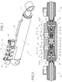
- This hydraulic cylinder 1 comprises a barrel 2, substantially cylindrical, inside which a piston 3 moves under the effect of the pressure of a hydraulic fluid.
- a rod 4 is conventionally mounted on the piston 3 and extends inside the barrel 2 on one side of this piston 3 and to the outside of the cylinder 1 where it can be used to lift loads.
- the piston 3 therefore separates the interior space of the barrel 2 into two hydraulically independent chambers: a chamber on the bottom side 5 and a chamber on the rod side 6.
- Each of these chambers has an orifice, respectively 7 and 8, which allows entry or release. hydraulic fluid outlet to fill or empty the chamber concerned.
- the hydraulic cylinder 1 is equipped with a safety block 9 which is mounted on the hydraulic circuit of the cylinder so that the fluid which supplies and emerges from the chambers of the cylinder passes through this safety block 9. It is thus connected by its outlet (orifice) 10 to the orifice 7 of the chamber 5 of the cylinder, and by its outlet (orifice) 11, via a external pipe 42 rigid, to orifice 8 of chamber 6 of the cylinder.
- a safety block 9 which is mounted on the hydraulic circuit of the cylinder so that the fluid which supplies and emerges from the chambers of the cylinder passes through this safety block 9. It is thus connected by its outlet (orifice) 10 to the orifice 7 of the chamber 5 of the cylinder, and by its outlet (orifice) 11, via a external pipe 42 rigid, to orifice 8 of chamber 6 of the cylinder.
- it has two inlets 12 and 13 which are respectively connected to the hydraulic circuit supplying the bottom side chamber 5 and the rod side chamber 6 of the hydraulic cylinder 1.
- the block shown thus comprises two hydraulic passages 43 through which the hydraulic fluid is forced to pass to fill or empty the chambers of the cylinder, the first connecting the inlet 12 to the outlet 10 and thus to the bottom side chamber 5, and the second connecting inlet 13 to outlet 11 and thus to the rod side chamber 6.
- this safety block 9 is preferably flanged or integrated into the barrel 2 of the cylinder 1. It can also be attached to the latter, and for example screwed to the barrel 2.
- the safety block 9 shown comprises two isolation devices 14. These two isolation devices 14 are preferably grouped together in a single casing or body 15. The device is thus more compact and more economical to manufacture. It is also much simpler and quicker to install. In addition, this reduces the hydraulic connections and the resulting risks of leaks.
- the body 15 is oriented longitudinally relative to the barrel 2 of the cylinder, that is to say that its main axis is parallel to the main axis of the barrel 2.
- Each of the isolation devices 14 comprises one of the hydraulic passages 43 and two closing devices 16, arranged one after the other, in series. These shutter devices 16 are of different nature.
- the first of these closing devices 16 is a mechanical non-return valve 17 with shutter 18 which is provided passing under the action of the hydraulic fluid in the direction corresponding to the entry of the fluid into the chamber concerned.
- This mechanical non-return valve 17 can be of any nature. This is for example a non-return valve with a conical needle 44 as for example on the Figure 21 or a ball check valve 19 as shown in the other figures.
- Each of the non-return valves 17 shown contains a substantially cylindrical bore 20 in which a shutter 18, ball 21 or needle 45 moves.
- This bore 20 ends in a narrower part forming a seat 22 for the shutter 18 when it finds itself resting against it, thus closing the valve in a watertight manner.
- the shutter 18 is held against its seat 22 preferably by a return spring 23 located in the bore 20 .
- the second of these shutter devices 16 is a preactuator hydraulic 24 whose opening and closing are independent of the presence or absence of hydraulic fluid in the hydraulic passage 43 concerned.
- This is preferably a solenoid valve 25, for example a valve, as shown in the figures.
- the second shutter device 16 is a solenoid valve 25 for each isolation device 14.
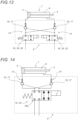
- a preactuator 24 of another type or controlled differently, or even a different configuration are however also possible, such as for example that shown in the Figure 14 .
- the solenoid valve 25 with flap shown comprises a rod 26 ending in a conical shutter 27 which is received in a seat 28 of complementary conical shape and which closes the flap in a watertight manner when it finds itself resting on it.
- the position of the rod 26 is controlled electrically and thereby that of the conical shutter 27 which is alternately pressed against or away from the seat 28.
- the conical shutter 27 is preferably kept resting on its seat 28 by a return spring 29 which thus ensures positive security opposing any circulation of hydraulic fluid in the absence of electricity.
- the seats 22 and 28 of the closing devices 16 can be shaped directly in the part forming the body 15 of the isolation device 14, or can also be made in an independent part which is mounted on the body of the isolation device.
- This independent part can advantageously be made of a material other than that of the body of the isolation device 14, in particular bronze, plastic or other.
- a seal for example an O-ring, can, if necessary, complete the seal at this level.
- the two shutter devices 16 being of completely different nature, one being mechanically actuated directly by the pressure of the fluid present in the hydraulic passage 43, and the other being controlled for example electrically, and being made with preferably different shutters without common mode, security is reinforced compared to known prior devices. It is indeed very unlikely that they will leak simultaneously, either from the start or over time, as the parts do not come from the same series and evolve differently over time. A simultaneous leak from these two closing devices 16 which follow one another is therefore highly improbable, which makes the isolation devices 14 and the safety block 9 which contains them, extremely safe.
- the two shutter devices 16 are arranged one after the other, the seat 28 of the valve the solenoid valve 25 being shaped in the extension of the bore 20. It is however possible that one or more elements be interposed between the two shutter devices 16 in series.
- the preactuator 24 (here the solenoid valve 25) is arranged on the side closest to the relevant chamber of the cylinder, relative to the mechanical non-return valve 17.
- the preactuator 24 here the solenoid valve 25
- the solenoid valve 25 is arranged on the side closest to the relevant chamber of the cylinder, relative to the mechanical non-return valve 17.
- other arrangements are possible.
- this arrangement is advantageously more secure because it makes it possible to guarantee double security of locking by the two shutter devices 16 in series, even when the circuit is under pressure, i.e. i.e. when a pressurized fluid is sent into the hydraulic supply circuit and arrives via one of the inlets 12 or 13, the hydraulic preactuator 24 (solenoid valve 25) and the mechanical non-return valve 17 remaining closed.
- the two isolation devices 14 may include a single common hydraulic preactuator 24, serving for the two hydraulic passages 43 of the two isolation devices 14, for example in the form of a four-port valve 25a.
- the second closing device 16 is thus a single four-port valve 25a, mounted on the two hydraulic passages 43, in series with the mechanical non-return valves 17 of the first closing device 16, which simultaneously closes or releases the two hydraulic passages 43 depending on whether it is controlled or not, that is to say depending on whether it is electrically powered or not in the preferred case shown of a solenoid valve.
- the security block 9 shown on the figures 2 to 8 further comprises a control part 30 capable of causing the opening of the mechanical non-return valve 17. It is a mechanical part located near the mechanical non-return valve 17 and which moves in the direction of it. this, in order to push its shutter 18 to cause it to open.
- control part 30 comprises a projecting lateral finger 31, which extends in the direction of the valve 19 and which is capable of engaging through the seat 22 of this valve , in order to push the ball 21 and thus cause the opening of the valve 19.
- control part 30 can advantageously be a sliding shuttle serving as a boundary for the two separate hydraulic circuits which independently supply the two chambers 5 and 6 of the cylinder 1.
- Each of the lateral faces 32 and 33 of this shuttle is thus in communication with one of these hydraulic circuits.
- a perimeter seal 34 mounted on this shuttle can optionally complete the barrier formed by it and ensure sealing between the two hydraulic circuits, while allowing the longitudinal sliding of the control part 30.
- This seal thus makes it possible to guarantee that the All of the hydraulic fluid sent ends up in the corresponding chamber of the cylinder and causes the rod 4 of the cylinder to retract or exit the expected length. This is particularly important in the case where the cylinder is part of a set of several cylinders which must act symmetrically.
- the movement of the control part 30 towards the mechanical non-return valve 17 is caused automatically by the pressure of the hydraulic fluid.
- control part 30 is preferably kept away from the mechanical non-return valve 17 by a return spring 35.
- the two isolation devices 14 are also paired, that is to say that their operation is linked to each other and is not independent.
- the security block 9 only includes a single piece of control 30, arranged between the two hydraulic passages 43 of the two isolation devices 14, and capable of alternately causing the opening of the mechanical non-return valve 17 of each of these two isolation devices 14.
- This single control part 30 is preferably a central sliding shuttle which comprises on each of these lateral faces 32 and 33 a projecting lateral finger 31, extending in the direction of one of the hydraulic passages 43.
- this control part 30 moves towards one of these hydraulic passages 43, the protruding lateral finger 31 located on this side pushes the shutter 18, here the ball 21, of the non-return valve 17 concerned and thus causes its opening.
- the projecting lateral fingers 31 of the control part 30 are however designed too short by construction, to simultaneously reach the two shutters 18 of the two mechanical non-return valves 17. A longitudinal clearance is thus guaranteed, and even in the event of incorrect positioning, the control part 30 cannot cause the two mechanical non-return valves 17 of the two hydraulic passages 43 to open simultaneously.
- control part 30 can be retained in the central position, between the two isolation devices 14, by two opposite return springs 35, which, when present, each act on one of the lateral faces 32, 33 of the single control part 30 to return it to a substantially central position.
- return springs 35 which, when present, each act on one of the lateral faces 32, 33 of the single control part 30 to return it to a substantially central position.
- the single control part 30 when the single control part 30 is in this central position, its projecting lateral fingers 31 are too short by construction to reach the shutters 18 of the mechanical non-return valves 17 opposite.
- the safety block 9 has four different operating states, depending on whether the operator controls the extension or retraction of the rod 4 of this cylinder, the extension or retraction of the rod of another cylinder of the hydraulic circuit or in l absence of order from him.
- This locked state corresponds to a safe equilibrium position, in which all the cylinders of the circuit are kept stationary possibly under load, and in which the operator does not give any command.
- this is for example the safety position adopted while the vehicle is being driven.
- control part 30 is in a central or quasi-central equilibrium position and its finger(s) protruding side laterals 31 are distant from the balls 21 of the mechanical non-return valves 17.
- control part 30 In a variant not comprising springs 35, the control part 30 would be in a random position between the two mechanical non-return valves 17. However, even if one of its projecting lateral fingers 31 was in contact with the ball 21 of one of these mechanical non-return valves 17, the mass and inertia of the control part 30 would be too low for its protruding lateral finger 31 to be able to push the ball 21 sufficiently hard to cause the opening of the valve anti-return 17 concerned in the absence of hydraulic pressure, under the effect of vibrations for example.
- the two mechanical non-return valves 17 are in the closed position, their ball 21 being pressed against their respective seat 22 in a sealed manner by the return springs 23.
- each of the chambers on the bottom side 5 and on the rod side 6 of the cylinder is locked from sealed manner by two successive closing devices 16, the hydraulic fluid present in these chambers not being able to escape. The position of the rod is therefore blocked by the hydraulic flow lock.
- This state is particularly safe, because the position of the rod in the loaded state is maintained even in the event of an internal leak between the two chambers of the cylinder. Indeed, in the event of transfer of oil from the bottom side chamber 5 to the rod side chamber 6, the pressure rises in the two chambers 5, 6 of the cylinder 1. But as the oil, which is incompressible, cannot escape through the isolation device 14 of the safety block 9 of which the two successive closing devices 16 are closed, the piston 3 cannot move and bring in the rod 4 by reducing the overall volume in which the fluid is located. The load is thus held safely.
- the operator When the operator wishes to control a movement of the rod 4 of the cylinder 1, he begins by electrically supplying the two solenoid valves 25 of the safety block 9 of the cylinder concerned. In the presence of electricity and as symbolized by the white arrows, the rods 26 of the solenoid valves move and move the conical shutters 27 away from their seats 28. The solenoid valves 25 are then open.
- the operator controls the sending of oil under pressure through the inlet 12 of the safety block 9, in order to fill the chamber on the bottom side 5 of the cylinder 1, in passing through the corresponding hydraulic passage 43 and the orifice 7.
- This pressurized fluid entering through the inlet 12, presses against the side face 32 of the control part 30 and pushes the latter away from the isolation device 14 on the bottom side, towards the isolation device 14 on the rod side.
- the pressurized fluid pushes the ball 21 of the mechanical non-return valve 17. Under the pressure of the fluid, it detaches from its seat 22 and lets in the fluid under pressure. The isolation device 14 on the bottom side is then completely open and pass-through.
- the hydraulic fluid under pressure continues its path in the hydraulic passage 43 through the solenoid valve 25 then to the outlet 10 of the safety block 9. It then enters the bottom side chamber 5 of the cylinder 1 through its orifice 7. L
- the pressurized oil pushes the piston 3, thus causing it to move towards the rod side chamber 6 and the exit of the rod 4 towards the outside of the cylinder.
- the hydraulic fluid then arrives at the level of the hydraulic passage 43 of the second isolation device 14 of the safety block 9, the solenoid valve 25 of which has been opened electrically and the mechanical non-return valve 17 of which is forced open by the control part 30. Indeed, under the pressure of the hydraulic fluid entering through the inlet 12, the control part 30 has moved closer to the mechanical non-return valve 17 of the isolation device 14 on the rod side, and its protruding lateral finger 31 taking birth of the lateral face 33 pushed the ball 21 out of its seat 22.
- the hydraulic fluid can therefore pass through the hydraulic passage 43 of the isolation device 14 on the rod side, the two closing devices 16 of which are open, and leave the safety block 9 via its inlet 13 to return to the reservoir.
- the safety block 9 is then in the closed position.
- the operator disconnects the solenoid valves 25 from the safety block 9, which, deprived of electricity, automatically return to the closed position, the return springs 29 pushing back the rods 26 which causes the conical shutters 27 to return against their seats 28.
- the safety block 9 and the associated cylinder 1 then find themselves in the secure locked state described previously.
- the hydraulic fluid which arrives at the level of the isolation device 14 on the rod side can pass through it, passing through the mechanical non-return valve 17 of which it pushes the ball 21, then the solenoid valve 25, and goes to fill the chamber on the rod side 6 of the cylinder.
- the hydraulic fluid present in the bottom side chamber 5, expelled by the movement of the piston 3, is evacuated through the orifice 7 through the safety block 9. It enters through the outlet 10 into the isolation device 14 on the side bottom, of which the two closing devices 16 are open, and passes through the corresponding hydraulic passage 43. It then leaves the security block 9 via its entrance 12 to return to the tank.
- control part 30 returns to its central equilibrium position and the balls 21 of the two mechanical non-return valves 17 automatically return to center on their seat 22, closing these valves in a watertight manner.
- the safety block 9 is then in the closed position.
- the safety blocks 9 of the other cylinders of the hydraulic circuit are in the inactive state shown on the figures 7 and 8 . They thus guarantee that the unselected cylinders are maintained in position, the rods 4 of which remain stationary.
- the solenoid valves 25 of the safety block 9 are not electrically powered. They therefore remain closed and oppose the passage of the hydraulic fluid under pressure which arrives via one of the inlets 12 or 13 of the safety block 9 (depending on the nature of the movement controlled for the active cylinder) and which can possibly cause the opening of the mechanical non-return valves 17. They also oppose the return of the hydraulic fluid to the reservoir.
- each of their isolation devices 14 comprises two closing devices 16 in series which are each time ball check valves 19.
- the opening of the two check valves is necessarily linked and occurs as soon as hydraulic fluid under pressure arrives at one of the inlets of the safety block 9, which automatically results in a movement of the cylinder rod (inward or outward depending on the supply side).
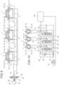
- the first example of a hydraulic circuit includes three cylinders 1 which we wish to be able to operate independently of each other. Each of these cylinders 1 is equipped with a safety block 9.
- the hydraulic fluid comes from a reservoir 36 and is sent into the circuit by a pumping device 37.
- Each of the hydraulic distributors 39 has three positions.
- the first interrupts the circulation of hydraulic fluid to hold the cylinder in position. This is the rest position where no flow exits towards the cylinders, which generally corresponds to a centered position of the drawer obtained thanks to return springs.
- the second puts the pumping device 37 in communication with the chamber bottom side 5 and the reservoir 36 with the rod side chamber 6 of the cylinder 1 corresponding to control the output of the cylinder rod, and the third puts the pumping device 37 in communication with the rod side chamber 6 and the reservoir 36 with the chamber on the bottom side 5 of the corresponding cylinder to control the retraction of the cylinder rod.
- the hydraulic circuit also includes numerous passages or pipes 40. In fact, whatever the configuration of the circuit, there must be at least two passages or pipes 40 at the inlet and two passages or pipes 40 at the outlet of each hydraulic distributors 39 in order to allow them to fulfill their function, which makes at least six passages or pipes 40 at the entrance and exit of the distribution block 38 for a circuit with three cylinders.
- the operator must then place the distributor corresponding to the cylinder to be actuated in the second or third position depending on whether he wishes to extend or retract the rod of the cylinder, the control of this distributor being generally manual.
- the operator When the cylinder rod has reached the desired position, the operator replaces the corresponding hydraulic distributor 39 in the first position and can then actuate another cylinder or stop the pumping device 37 in order to stop the circulation of hydraulic fluid.
- the distribution block 38 of the hydraulic circuit according to the invention therefore comprises only a single hydraulic distributor 39 which is connected to all of the cylinders 1 of the circuit.
- this hydraulic distributor 39 has three positions, the first interrupting the circulation of the hydraulic fluid, the second putting the pumping device 37 in communication with simultaneously all the chambers on the bottom side 5 of all the cylinders 1 and the reservoir 36 with simultaneously all the rod side chambers 6 of all cylinders 1, and the third putting the pumping device 37 into communication with simultaneously all the chambers on the rod side 6 of all the cylinders 1 and the reservoir with simultaneously all the chambers on the bottom side 5 of all the cylinders 1.
- this distributor 39 can have a proportional effect in order to allow the operator to manage the entry or exit speed of the cylinders 1.
- the hydraulic circuit has many fewer pipes 40 than in the previous example, because only two pipes 40 are necessary at the inlet and outlet of the distribution block 38, regardless of the number of cylinders in the circuit.
- the operator wishes to control the movement of one of the cylinders 1, he controls the opening of the two preactuators 24 of the safety block 9 of the cylinder concerned, for example by powering them electrically if they are solenoid valves 25.
- the preactuators 24 of the safety blocks of all the other cylinders are kept closed, for example for solenoid valves 25 by leaving them without electrical voltage.
- the control of these solenoid valves 25 can easily be carried out remotely, in an ergonomic manner for the operator, for example by means of a button control panel, a device on the vehicle dashboard, or even by means of from a wireless device such as a remote control, tablet, laptop or smartphone.
- the hydraulic fluid is then sent towards all of the cylinders 1, but as all the preactuators 24 are closed with the exception of that of the chosen cylinder 1, the hydraulic fluid does not pass through the safety blocks 9 of the other cylinders and do not enter their rooms. Although under hydraulic pressure, the unselected cylinders remain locked in position.
- the electrical supply to the solenoid valves 25 of the chosen cylinder 1 is also cut off, in order to close these solenoid valves 25 and thus place the block safety in locked state.
- the second example of hydraulic circuit shown on the figures 11 And 12 comprises six cylinders 1 equipped with a safety block 9, which are organized in three pairs of two cylinders 1 which we wish to be able to operate independently of each other.
- This type of circuit where the actuators operate in pairs is frequently encountered in practice. They are, for example, used in car transporter applications.
- the two cylinders must have synchronized movements. To do this, it is necessary to add flow divider components 41 to the hydraulic circuit which ensure the synchronization of the movements of the two cylinders of each pair of cylinders 1.
- a distribution block 38 which includes a hydraulic distributor 39 for each of the pairs of cylinders 1, as well as a flow divider component 41 for each of the pairs of cylinders 1.
- This flow divider component 41 which operates both in division and in reconstitution of flow, must be placed on one of the pipes 40 leaving from each hydraulic distributor 39.
- the flow divider component 41 is placed on one of the two pipes 40 which leave from the hydraulic distributor 39 and to which each of the cylinders 1 of the circuit are connected. This flow divider component 41 thus divides or recomposes the flow for each of the pairs of cylinders simultaneously. As a result, it ensures the synchronism of the movements of each of the pairs of cylinders 1 whose movement is controlled by the operator.
- the hydraulic circuits according to the invention being simpler and comprising fewer components than those of the prior art, they are advantageously less expensive and easier to set up. Likewise, their maintenance is easier.
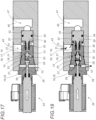
- This hydraulic cylinder 1 comprises a barrel 2 which contains a single chamber 6' inside which the rod 4 moves under the effect of the pressure of the hydraulic fluid.
- a single 7' orifice allows the entry or exit of hydraulic fluid to fill or empty the 6' chamber.
- This cylinder 1 is equipped with a safety block 9 according to the invention, which is connected by its outlet 10 to the orifice 7' of the chamber 6' of the cylinder.
- Block 9 has two inlets 12 and 46 which are connected to the hydraulic supply circuit of cylinder 1.
- the safety block 9 this time only includes a single isolation device 14 in its body 15, with a single hydraulic passage 43 which connects the inlet 12 to the outlet 10.
- the block 9 includes two shutter devices 16 , different and arranged in series in the hydraulic passage 43: a mechanical non-return valve 17 with shutter 18, for example a ball, passing in the direction of the entry of the fluid into the chamber 6', and a hydraulic preactuator 24, for example a solenoid valve 25 preferably with a valve as shown.
- the preactuator 24 is located closer to the relevant chamber of the cylinder than the mechanical non-return valve 17, an inverted arrangement is also possible and advantageous for the reasons stated above.
- the safety block 9 shown further comprises a control part 30 which comprises a single protruding lateral finger 31 extending in the direction of the mechanical non-return valve 17 and which can cause the latter to open when the control part 30 moves in its direction.
- This control part 30 is in hydraulic communication via its side face 32 with the hydraulic passage 43 which opens via the inlet 12, and via its side face 33 with a control passage 47 which opens from the block 9 via the dedicated inlet 46 to this function.
- This security block 9 has four different operating states.
- This locked state corresponds to the safe equilibrium position, in which all the cylinders of the circuit are kept immobile in the absence of a command from the operator.
- the chamber 6' of the cylinder is sealed in a sealed manner by two successive closing devices 16 in the closed position.
- the position of rod 4 is blocked by the hydraulic flow lock.
- the operator controls the opening of the solenoid valve 25 by powering it electrically.
- Oil under pressure is sent through the inlet 12 of the safety block 9 and enters the hydraulic passage 43 of the device.
- the fluid presses against the side face 32 of the control part 30 and pushes it away from the mechanical non-return valve.
- the pressurized fluid also pushes the ball 21 of the mechanical non-return valve 17 which opens and becomes pass-through.
- the hydraulic fluid continues its path through the solenoid valve 25, then leaves the safety block 9 through its outlet 10 and enters the chamber 6' of the cylinder 1 through its orifice 7'.
- the oil under pressure pushes the rod 4 towards the outside, thus causing it to come out.
- the electrical supply to the solenoid valve 25 is cut off, which automatically causes it to move to the closed position.
- the security block 9 and the associated cylinder 1 then finds itself in the secure locked state described previously.
- the operator controls the opening of the solenoid valve 25 by powering it electrically.
- Pressurized oil is this time sent through the inlet 46 of the safety block 9 and enters the control passage 47 of the device.
- the fluid presses against the lateral face 33 of the control part 30 and pushes the latter against the mechanical non-return valve 17.
- the protruding lateral finger 31 forces the mechanical non-return valve 17 to open by pushing the ball 21 out of its seat 22.
- the hydraulic fluid can then escape from the chamber 6' via the orifice 7' and the outlet 10, then pass through the safety block 9 by taking the hydraulic passage 43 through the solenoid valve 25 and the check valve. -mechanical return 17, and leave the safety block 9 via its entrance 12 to return to the tank.
- the electrical supply to the solenoid valve 25 is also cut off, which automatically causes it to go into the closed position.
- the safety block 9 and the associated cylinder 1 then find themselves in the secure locked state.
- the safety block 9 finds itself in this state when the operator controls the movement of another cylinder in the hydraulic circuit.
- the solenoid valve 25 of the safety block 9 is not electrically powered and therefore remains closed. It thus opposes the passage of the hydraulic fluid under pressure which arrives through the inlet 12 and causes the opening of the mechanical non-return valve 17 when the output of the active cylinder rod is controlled.
- this safety block 9 comprises two inlets 12 and 46 which are connected to the hydraulic supply circuit of the cylinder 1, and a single isolation device 14 with a single hydraulic passage 43 which connects its inlet 12 to its outlet 10 , which is intended to be placed in communication with the orifice 7' of the chamber 6' of the cylinder.
- a mechanical check valve 17 with shutter 18 which this time is a check valve with a conical needle 44, passing in the direction from the entry of the fluid into the chamber 6', and a hydraulic preactuator 24, for example a solenoid valve 25 preferably with a valve as shown.
- the mechanical non-return valve 17 opens under the direct thrust of the hydraulic fluid penetrating through the inlet 46, and no longer under the indirect thrust of the latter via a control part.
- hydraulic fluid under pressure enters through the inlet 46 into the control passage 47, it directly pushes the face 48 opposite the needle 45 which extends into the control passage 47 and thus causes the opening of the valve mechanical anti-return 17.
- An annular seal 49 is preferably provided around the stem of the needle 45 in order to avoid any fluid crossing between the hydraulic passage 43 and the control passage 47.
- a double-acting cylinder 1 equipped with another example of safety block 9 according to the invention.
- This comprises two separate isolation devices 14 and 14', each equipping one of the chambers 5 or 6 of the cylinder, and which can each be protected in a different casing or in a common casing.
- isolation devices 14 or 14' corresponds to that which has been described for a single-acting cylinder with reference to the figures 16 to 20 .
- the pairing for the operation of the two isolation devices 14 and 14' is not done by means of a part of single control 30, but by a division of the supply lines 40 and 40'.
- the pipe 40 which is intended to supply hydraulic fluid to the chamber on the bottom side 5 of the cylinder, is divided into a portion of pipe 40a which opens into the inlet 12 of the isolation device 14 and a portion of pipe 40b which opens into the inlet 46' of the isolation device 14'.
- the pipe 40' which is intended to supply hydraulic fluid to the rod side chamber 6 of the cylinder, is divided into a portion of pipe 40a' which opens into the inlet 12' of the isolation device 14' and a portion of pipe 40b' which opens into the inlet 46 of the isolation device 14.
- the pressurized fluid When the pressurized fluid is sent into the pipe 40, it enters, via the pipe portion 40a, into the inlet 12 of the device 14 and pushes the ball 21 of the mechanical non-return valve 17 which becomes passer-by.
- the fluid then passes through the solenoid valve 25 and enters the chamber 6 of the cylinder 1 through its orifice 7 where it pushes the rod 4 to cause its exit.
- pressurized fluid also enters the inlet 46' of the device 14', via the pipe portion 40b.
- This fluid causes the movement in the direction of the mechanical non-return valve 17' of the control part 30' which pushes the ball 21' thereof by means of its protruding lateral finger 31'.
- the mechanical non-return valve 17' then becomes passing and the fluid present in the rod side chamber 6 can escape, as the rod 4 exits, via the orifice 8, the solenoid valve 25' , the valve 17', the inlet 12', the pipe portion 40a' and the pipe 40'.
Landscapes
- Engineering & Computer Science (AREA)
- General Engineering & Computer Science (AREA)
- Mechanical Engineering (AREA)
- Physics & Mathematics (AREA)
- Fluid Mechanics (AREA)
- Fluid-Pressure Circuits (AREA)
- Actuator (AREA)
Claims (17)
- Sicherheitsblock (9) mit serieller Doppelabsperrung für einen hydraulischen Hubzylinder (1), der eine Last anheben, absenken und in der Luft halten kann, um durch die Sperrung des Hydraulikflusses zu gewährleisten, dass die Kolbenstange (4) des Hydraulikzylinders (1) in Position gehalten wird, wobei der Sicherheitsblock (9) für den Einbau in den Hydraulikkreis vorgesehen ist, der den Zylinder (1) mit Hydraulikflüssigkeit versorgt, wobei der Sicherheitsblock (9) Folgendes umfasst:- zwei Einlässe (12, 13, 46, 12', 46') zur Verbindung mit dem Hydraulikkreis und mindestens einen Auslass (10, 11) zur Verbindung mit der Öffnung (7, 8) einer Kammer (5, 6, 6') des Zylinders;- einen hydraulischen Durchgang (43) zwischen einem ersten dieser beiden Einlässe (12, 13, 12') und mindestens einem Auslass (10, 11), der so vorgesehen ist, dass die Zylinderkammer nur über diesen hydraulischen Durchgang (43) gefüllt und entleert werden kann, und- zwei Verschlussvorrichtungen (16), die in Reihe in dem hydraulischen Durchgang (43) angeordnet sind, so dass die Kammer (5, 6, 6') des Zylinders durch zwei aufeinanderfolgende Verschlussvorrichtungen (16) dicht verschlossen werden kann, wobei die erste dieser Verschlussvorrichtungen (16) ein mechanisches Rückschlagventil (17) mit Verschluss (18) ist, das unter dem direkten Druck der Hydraulikflüssigkeit, das durch den ersten der beiden Eingänge (12, 13, 12') in den hydraulischen Durchgang eindringt, durchlässig ist, um das Befüllen der besagten Zylinderkammer zu ermöglichen, und das auch unter der direkten oder über die Betätigung eines Steuerteiles (30) erfolgenden Schubkraft der Hydraulikflüssigkeit, die durch den zweiten der beiden Einlässe (12, 13, 46, 46') eintritt, durchlässig ist, um das Entleeren der besagten Zylinderkammer zu ermöglichen,Sicherheitsblock (9), dadurch gekennzeichnet, dass die beiden Verschlussvorrichtungen (16) von unterschiedlicher Art sind, dass die zweite dieser Verschlussvorrichtungen (16) ein hydraulischer Vorbetätiger (24) ist, dessen Öffnen und Schließen unabhängig von der Anwesenheit oder Abwesenheit von Hydraulikflüssigkeit an den beiden Einlässen (12, 13, 46, 12', 46') und in dem hydraulischen Durchgang (43) ist.
- Sicherheitsblock (9) nach Anspruch 1, dadurch gekennzeichnet, dass die erste dieser Verschlussvorrichtungen (16) ein Kugelrückschlagventil (19) oder ein Rückschlagventil mit konischer Nadel (44) ist.
- Sicherheitsblock (9) nach Anspruch 1 oder 2, dadurch gekennzeichnet, dass er ein Steuerteil (30) umfasst, welches sich in der Nähe des mechanischen Rückschlagventils (17) befindet, wobei sich dieses Steuerteil unter dem Druck der Hydraulikflüssigkeit, die durch den zweiten dieser beiden Eingänge (12, 13, 46, 46') eindringt und auf den Verschluss (18) drückt, um das Öffnen des mechanischen Rückschlagventils (17) zu bewirken, in Richtung des mechanischen Rückschlagventils (17) verschiebt.
- Sicherheitsblock (9) nach einem der Ansprüche 1 bis 3, dadurch gekennzeichnet, dass der hydraulische Vorbetätiger (24) ein elektrisch, pneumatisch oder hydraulisch betätigtes Ventil oder ein vorgesteuertes Rückschlagventil ist.
- Sicherheitsblock (9) nach einem der Ansprüche 1 bis 3, dadurch gekennzeichnet, dass der hydraulische Vorbetätiger (24) ein Magnetventil (25) ist oder mittels eines Magnetventils (25) gesteuert wird.
- Sicherheitsblock nach einem der Ansprüche 1 bis 5, dadurch gekennzeichnet, dass die beiden Verschlussvorrichtungen (16) direkt aufeinander folgend angeordnet sind.
- Sicherheitsblock (9) nach einem der Ansprüche 1 bis 6 für einen doppeltwirkenden Hydraulikzylinder mit zwei Kammern (5, 6), dadurch gekennzeichnet, dass der Sicherheitsblock (9) folgendes umfasst:- einen zweiten Ausgang (10, 11), so dass die Ausgänge (10, 11) dazu bestimmt sind, für den ersten mit der Öffnung (7) der ersten der beiden Kammern (5) des Zylinders und für den zweiten mit der Öffnung (8) der zweiten der beiden Kammern (6) des Zylinders verbunden zu werden;- einen zweiten hydraulischen Durchgang (43), so dass die beiden hydraulischen Durchgänge (43) für den ersten zwischen dem ersten der mindestens zwei Einlässe (12) und dem ersten der beiden Auslässe (10) und für den zweiten zwischen dem zweiten der mindestens zwei Einlässe (13, 12') und dem zweiten der beiden Auslässe (11) liegen, die so vorgesehen sind, dass jede der beiden Kammern (5, 6) des Zylinders nur durch einen der beiden hydraulischen Durchgänge (43) gefüllt und entleert werden kann, und- zwei zusätzliche Verschlussvorrichtungen (16) unterschiedlicher Art, so dass zwei Verschlussvorrichtungen (16) in jedem dieser beiden hydraulischen Durchgänge (43) in Reihe angeordnet sind, so dass jede der beiden Kammern (5, 6) des Zylinders durch zwei aufeinanderfolgende Verschlussvorrichtungen (16) dicht verriegelt werden kann, wobei die erste Verschlussvorrichtung der beiden zusätzlichen Verschlussvorrichtungen ein mechanisches Rückschlagventil (17) mit einem Verschluss (18) ist, das unter dem direkten Schub der Hydraulikflüssigkeit, die in den betreffenden hydraulischen Durchgang durch den entsprechenden Einlass eintritt, durchlässig ist, um das Füllen der betreffenden Kammer des Zylinders zu ermöglichen, und die auch unter dem direkten oder über die Wirkung eines Steuerteils (30) erfolgenden Druck der Hydraulikflüssigkeit, die durch einen anderen der mindestens zwei Einlässe (12, 13, 46, 46') eindringt, durchlässig ist, um das Entleeren der betreffenden Kammer des Zylinders zu ermöglichen, und die zweite Verschlussvorrichtung der beiden zusätzlichen Verschlussvorrichtungen ein Vorbetätiger (24) ist, dessen Öffnen und Schließen unabhängig von der Anwesenheit oder Abwesenheit von Hydraulikflüssigkeit an diesen mindestens zwei Einlässen (12, 13, 46, 12', 46') und in dem betreffenden hydraulischen Durchgang (43) ist.
- Sicherheitsblock (9) nach Anspruch 7, dadurch gekennzeichnet, dass in jedem hydraulischen Durchtgang (43), um die Entleerung der betreffenden Kammer des Zylinders zu ermöglichen, das mechanische Rückschlagventil (17) mit Verschluss (18) vorgesehen ist, das unter dem Druck der Hydraulikflüssigkeit durchlässig ist, die durch den Einlass des anderen hydraulischen Durchgangs (43) oder durch einen anderen Einlass (43, 43'), der dieser Funktion gewidmet ist, eindringt.
- Sicherheitsblock (9) nach Anspruch 7 oder 8, dadurch gekennzeichnet, dass er einen einzigen Körper (15) aufweist, in dem die beiden hydraulischen Durchgänge (43) angeordnet sind.
- Sicherheitsblock (9) nach einem der Ansprüche 7 bis 9, dadurch gekennzeichnet, dass er ein spezielles Steuerteil (30) für das mechanische Rückschlagventil (17) jedes der beiden hydraulischen Durchgänge (43) aufweist.
- Sicherheitsblock (9) nach einem der Ansprüche 7 bis 9, dadurch gekennzeichnet, dass er ein einziges Steuerteil (30) umfasst, das den mechanischen Rückschlagventilen (17) der beiden hydraulischen Durchgänge (43) gemeinsam ist und das geeignet ist, abwechselnd das Öffnen des mechanischen Rückschlagventils (17) jedes der beiden hydraulischen Durchgänge (43) zu bewirken.
- Sicherheitsblock (9) nach einem der Ansprüche 6 bis 11, dadurch gekennzeichnet, dass er einen hydraulischen Vorbetätiger (24) umfasst, der den beiden hydraulischen Durchgängen (43) gemeinsam ist und als zweite Verschlussvorrichtung (16) für jeden der beiden hydraulischen Durchgänge (43) dient.
- Hydraulischer Zylinder (1), der mit einem Sicherheitsblock ausgestattet ist, dadurch gekennzeichnet, dass der Sicherheitsblock einem der Ansprüche 1 bis 12 entspricht.
- Hydraulikkreis mit mehreren Hydraulikzylindern (1), mehreren Sicherheitsblöcken (9), wobei jeder Zylinder (1) mit einem Sicherheitsblock (9) ausgestattet ist und eine Kolbenstange (4) und eine oder zwei Kammern (5, 6) umfasst, die jeweils über einen hydraulischen Durchgang (43) des Sicherheitsblocks (9) versorgt werden, einen Tank (36) für Hydraulikflüssigkeit, einen Verteilerblock (38), eine Einheit an Rohrleitungen (40), die den Tank (36) über den Verteilerblock (38) mit den Zylindern (1) verbinden, um jede der Kammern (5, 6) der Zylinder (1) zu befüllen und/oder zu entleeren, sowie eine Pumpvorrichtung (37), die es ermöglicht, die Hydraulikflüssigkeit in den Rohren (40) umzuwälzen, wobei der Hydraulikkreis dadurch gekennzeichnet ist,dass der Verteilerblock (38) einen einzigen hydraulischen Verteiler (39) mit drei Positionen umfasst, wobei die erste den Umlauf der Hydraulikflüssigkeit unterbricht, die zweite die Pumpvorrichtung (37) und den Tank (36) mit allen Sicherheitsblöcken (9) aller Zylinder (1) gleichzeitig auf eine Weise verbindet, die das Ausfahren der Kolbenstange aller Zylinder (1) bewirken kann, und die dritte die Pumpvorrichtung (37) und den Tank (36) mit allen Sicherheitsblöcken (9) aller Zylinder (1) gleichzeitig in einer Weise verbindet, die das Einfahren der Kolbenstange aller Zylinder (1) bewirken kann; dass die Sicherheitsblöcke (9) Sicherheitsblöcke nach einem der Ansprüche 1 bis 12 sind; unddass die hydraulischen Vorstellglieder (24) eines jeden der Sicherheitsblöcke (9) so gesteuert werden, dass sie unabhängig von den hydraulischen Vorstellgliedern der anderen Sicherheitsblöcke (9) geöffnet oder geschlossen werden können.
- Hydraulikkreis nach Anspruch 14, dadurch gekennzeichnet, dass die hydraulischen Vorstellglieder (24) ferngesteuert sind.
- Hydraulikkreis nach Anspruch 14 oder 15, dadurch gekennzeichnet, dass die Zylinder (1) in mehreren Paaren von jeweils zwei Zylindern (1) angeordnet sind, die synchron arbeiten, und dass der Hydraulikkreis außerdem einen einzigen Strömungsteiler (41) umfasst, der die Synchronität der Bewegungen aller Zylinderpaare von Zylindern (1) sicherstellt.
- Hydraulikkreis nach einem der Ansprüche 14 bis 16, dadurch gekennzeichnet, dass es nur zwei Schläuche (40) am Auslass des Verteilerblocks (38) gibt, die in Richtung der Sicherheitsblöcke (9) verlaufen, wobei in dem einen die Hydraulikflüssigkeit umläuft, mit dem das Ausfahren der Kolbenstange aller Zylinder (1) bewirkt werden kann, und in dem anderen die Hydraulikflüssigkeit umläuft, mit dem das Einfahren der Kolbenstange aller Zylinder (1) bewirkt werden kann.
Applications Claiming Priority (3)
| Application Number | Priority Date | Filing Date | Title |
|---|---|---|---|
| FR1914566A FR3104653B1 (fr) | 2019-12-17 | 2019-12-17 | Bloc de securite a electrovanne pour verin et circuit hydraulique contenant plusieurs verins equipes de tels blocs |
| FR2008102A FR3104654B3 (fr) | 2019-12-17 | 2020-07-30 | Bloc de securite ameliore pour verin et circuit hydraulique contenant plusieurs verins equipes de tels blocs |
| PCT/FR2020/052516 WO2021123653A1 (fr) | 2019-12-17 | 2020-12-17 | Bloc de securite pour verin et circuit hydraulicue contenant plusieurs verins ecuipes de tels blocs |
Publications (3)
| Publication Number | Publication Date |
|---|---|
| EP4077950A1 EP4077950A1 (de) | 2022-10-26 |
| EP4077950B1 true EP4077950B1 (de) | 2023-11-08 |
| EP4077950C0 EP4077950C0 (de) | 2023-11-08 |
Family
ID=69468927
Family Applications (1)
| Application Number | Title | Priority Date | Filing Date |
|---|---|---|---|
| EP20848714.0A Active EP4077950B1 (de) | 2019-12-17 | 2020-12-17 | Sicherheitsblock für zylinder und hydraulische schaltung umfassend mehrere mit solchen blöcken ausgerüsteten zylinder |
Country Status (3)
| Country | Link |
|---|---|
| EP (1) | EP4077950B1 (de) |
| FR (2) | FR3104653B1 (de) |
| WO (1) | WO2021123653A1 (de) |
Families Citing this family (1)
| Publication number | Priority date | Publication date | Assignee | Title |
|---|---|---|---|---|
| FR3145952B1 (fr) | 2023-02-21 | 2025-01-10 | Lohr Ind | Dispositif de verrouillage d’un vérin hydraulique à commande électrohydraulique indirecte |
Citations (2)
| Publication number | Priority date | Publication date | Assignee | Title |
|---|---|---|---|---|
| WO2015112349A1 (en) * | 2014-01-22 | 2015-07-30 | Eaton Corporation | Poppet valve stop feature |
| EP3436706B1 (de) * | 2016-03-31 | 2020-04-22 | Lohr Industrie | Sichereitsblock mit doppeltem ventil für einen hydraulischen zylinder |
Family Cites Families (6)
| Publication number | Priority date | Publication date | Assignee | Title |
|---|---|---|---|---|
| GB634293A (en) * | 1945-08-28 | 1950-03-15 | Fairy Aviat Company Ltd | An electro-hydraulic valve applicable to hydraulic systems |
| DE3244840A1 (de) * | 1981-12-17 | 1983-06-30 | Edi System S.r.l., Modena | Normalerweise geschlossenes zweiwege-nadelventil mit elektromagnetischer steuerung |
| AT397135B (de) * | 1991-07-03 | 1994-02-25 | Weber Guenter | Einschraubventil |
| FR2755481B1 (fr) | 1996-11-07 | 1998-12-24 | Lohr Ind | Dispositif de maintien en position et sous charge d'un verin hydraulique |
| DE19925204B4 (de) * | 1999-06-01 | 2008-04-10 | Bosch Rexroth Aktiengesellschaft | Entsperrbares Lasthalteventil |
| US20120152629A1 (en) * | 2010-12-15 | 2012-06-21 | Mather Daniel T | Hydraulic system having load lock valve |
-
2019
- 2019-12-17 FR FR1914566A patent/FR3104653B1/fr active Active
-
2020
- 2020-07-30 FR FR2008102A patent/FR3104654B3/fr not_active Expired - Fee Related
- 2020-12-17 EP EP20848714.0A patent/EP4077950B1/de active Active
- 2020-12-17 WO PCT/FR2020/052516 patent/WO2021123653A1/fr not_active Ceased
Patent Citations (2)
| Publication number | Priority date | Publication date | Assignee | Title |
|---|---|---|---|---|
| WO2015112349A1 (en) * | 2014-01-22 | 2015-07-30 | Eaton Corporation | Poppet valve stop feature |
| EP3436706B1 (de) * | 2016-03-31 | 2020-04-22 | Lohr Industrie | Sichereitsblock mit doppeltem ventil für einen hydraulischen zylinder |
Also Published As
| Publication number | Publication date |
|---|---|
| FR3104654A3 (fr) | 2021-06-18 |
| WO2021123653A1 (fr) | 2021-06-24 |
| EP4077950A1 (de) | 2022-10-26 |
| FR3104653A1 (fr) | 2021-06-18 |
| FR3104654B3 (fr) | 2021-12-10 |
| FR3104653B1 (fr) | 2021-11-19 |
| EP4077950C0 (de) | 2023-11-08 |
Similar Documents
| Publication | Publication Date | Title |
|---|---|---|
| EP3436706B1 (de) | Sichereitsblock mit doppeltem ventil für einen hydraulischen zylinder | |
| FR2757208A1 (fr) | Bloc obturateur de puits avec arbres de belier partiellement egalises, ensemble formant belier qui l'equipe et procede pour fermer ce dernier | |
| FR2504972A1 (fr) | Tete d'essai de production souterraine et dispositif de commande d'ecoulement | |
| EP0935715A1 (de) | Haltevorrichtung einer hydraulischen arbeitszylinderstange | |
| FR2794101A1 (fr) | Actionneur pneumatique | |
| EP2454489B1 (de) | Hydraulische zufuhr- und rücksetzeinheit für eine hebeanordnung mit zwei separaten simultan betätigten elektrolagern | |
| CA3062434C (fr) | Circuit hydraulique de manoeuvre de train d'atterissage d'aeronef | |
| EP4077950A1 (de) | Sicherheitseinheit für einen zylinder und hydraulikkreislauf mit mehreren zylindern, die mit diesen einheiten ausgerüstet sind | |
| EP3268638B1 (de) | Verteilervorrichtung und druckbegrenzer, insbesondere für eine hydraulische stützvorrichtung auf einem fahrzeug und fahrzeug damit | |
| EP2105368B1 (de) | Hydraulikkreislauf für Waggon, insbesondere einen Schotterwagen | |
| EP1883736B1 (de) | Vorrichtung zur zuführung von öl zu einem auf einer trägervorrichtung angebrachten werkzeug und hydraulische verbindungsanordnung | |
| EP3724473B1 (de) | Abschnitt einer flüssigkeitsabflussleitung für eine turbomaschine | |
| WO2024175239A1 (fr) | Dispositif de verrouillage d'un vérin hydraulique à commande électrohydraulique indirecte | |
| EP3099577A1 (de) | Verbessertes treibstoffzufuhrsystem für ein raumfahrzeug | |
| FR2509391A1 (fr) | Valve de frein de securite hydraulique | |
| FR2566352A1 (fr) | Amplificateur hydraulique d'effort de freinage | |
| FR2666116A1 (fr) | Vanne de securite de l'espace annulaire et procede pour commander l'ecoulement de fluides entre des conduits tubulaires exterieur et interieur. | |
| EP3308057B1 (de) | Druckbegrenzungsvorrichtung, insbesondere für ein hydraulisches hilfssystem für fahrzeuge | |
| FR2482243A1 (fr) | Fusible fluidique | |
| BE512768A (de) | ||
| FR2667116A1 (fr) | Dispositif de pompage d'un fluide polyphasique. | |
| FR3070003B1 (fr) | Dispositif de regulation hydraulique pour systeme de commande avec amortissement pour rampe de pulverisation, et systeme comprenant ledit dispositif | |
| FR3082246A1 (fr) | Dispositif de verrouillage hydraulique | |
| EP3204675A1 (de) | Mehrwegeventil mit verschlussschieber, verwendung solch eines ventils zum kühlen und laden/entladen von bestrahlungszielen in einem kernreaktorbehälter | |
| FR3037376A1 (fr) | Dispositif de limitation de pression, notamment pour systeme d'assistance hydraulique de vehicules |
Legal Events
| Date | Code | Title | Description |
|---|---|---|---|
| STAA | Information on the status of an ep patent application or granted ep patent |
Free format text: STATUS: UNKNOWN |
|
| STAA | Information on the status of an ep patent application or granted ep patent |
Free format text: STATUS: THE INTERNATIONAL PUBLICATION HAS BEEN MADE |
|
| PUAI | Public reference made under article 153(3) epc to a published international application that has entered the european phase |
Free format text: ORIGINAL CODE: 0009012 |
|
| STAA | Information on the status of an ep patent application or granted ep patent |
Free format text: STATUS: REQUEST FOR EXAMINATION WAS MADE |
|
| 17P | Request for examination filed |
Effective date: 20220405 |
|
| AK | Designated contracting states |
Kind code of ref document: A1 Designated state(s): AL AT BE BG CH CY CZ DE DK EE ES FI FR GB GR HR HU IE IS IT LI LT LU LV MC MK MT NL NO PL PT RO RS SE SI SK SM TR |
|
| DAV | Request for validation of the european patent (deleted) | ||
| DAX | Request for extension of the european patent (deleted) | ||
| GRAP | Despatch of communication of intention to grant a patent |
Free format text: ORIGINAL CODE: EPIDOSNIGR1 |
|
| STAA | Information on the status of an ep patent application or granted ep patent |
Free format text: STATUS: GRANT OF PATENT IS INTENDED |
|
| INTG | Intention to grant announced |
Effective date: 20230804 |
|
| GRAS | Grant fee paid |
Free format text: ORIGINAL CODE: EPIDOSNIGR3 |
|
| GRAA | (expected) grant |
Free format text: ORIGINAL CODE: 0009210 |
|
| STAA | Information on the status of an ep patent application or granted ep patent |
Free format text: STATUS: THE PATENT HAS BEEN GRANTED |
|
| AK | Designated contracting states |
Kind code of ref document: B1 Designated state(s): AL AT BE BG CH CY CZ DE DK EE ES FI FR GB GR HR HU IE IS IT LI LT LU LV MC MK MT NL NO PL PT RO RS SE SI SK SM TR |
|
| REG | Reference to a national code |
Ref country code: GB Ref legal event code: FG4D Free format text: NOT ENGLISH |
|
| REG | Reference to a national code |
Ref country code: CH Ref legal event code: EP |
|
| REG | Reference to a national code |
Ref country code: DE Ref legal event code: R096 Ref document number: 602020020862 Country of ref document: DE |
|
| REG | Reference to a national code |
Ref country code: IE Ref legal event code: FG4D Free format text: LANGUAGE OF EP DOCUMENT: FRENCH |
|
| U01 | Request for unitary effect filed |
Effective date: 20231108 |
|
| U07 | Unitary effect registered |
Designated state(s): AT BE BG DE DK EE FI FR IT LT LU LV MT NL PT SE SI Effective date: 20231113 |
|
| U20 | Renewal fee for the european patent with unitary effect paid |
Year of fee payment: 4 Effective date: 20231218 |
|
| PG25 | Lapsed in a contracting state [announced via postgrant information from national office to epo] |
Ref country code: GR Free format text: LAPSE BECAUSE OF FAILURE TO SUBMIT A TRANSLATION OF THE DESCRIPTION OR TO PAY THE FEE WITHIN THE PRESCRIBED TIME-LIMIT Effective date: 20240209 |
|
| PG25 | Lapsed in a contracting state [announced via postgrant information from national office to epo] |
Ref country code: IS Free format text: LAPSE BECAUSE OF FAILURE TO SUBMIT A TRANSLATION OF THE DESCRIPTION OR TO PAY THE FEE WITHIN THE PRESCRIBED TIME-LIMIT Effective date: 20240308 |
|
| PG25 | Lapsed in a contracting state [announced via postgrant information from national office to epo] |
Ref country code: ES Free format text: LAPSE BECAUSE OF FAILURE TO SUBMIT A TRANSLATION OF THE DESCRIPTION OR TO PAY THE FEE WITHIN THE PRESCRIBED TIME-LIMIT Effective date: 20231108 |
|
| PG25 | Lapsed in a contracting state [announced via postgrant information from national office to epo] |
Ref country code: IS Free format text: LAPSE BECAUSE OF FAILURE TO SUBMIT A TRANSLATION OF THE DESCRIPTION OR TO PAY THE FEE WITHIN THE PRESCRIBED TIME-LIMIT Effective date: 20240308 Ref country code: GR Free format text: LAPSE BECAUSE OF FAILURE TO SUBMIT A TRANSLATION OF THE DESCRIPTION OR TO PAY THE FEE WITHIN THE PRESCRIBED TIME-LIMIT Effective date: 20240209 Ref country code: ES Free format text: LAPSE BECAUSE OF FAILURE TO SUBMIT A TRANSLATION OF THE DESCRIPTION OR TO PAY THE FEE WITHIN THE PRESCRIBED TIME-LIMIT Effective date: 20231108 |
|
| PG25 | Lapsed in a contracting state [announced via postgrant information from national office to epo] |
Ref country code: RS Free format text: LAPSE BECAUSE OF FAILURE TO SUBMIT A TRANSLATION OF THE DESCRIPTION OR TO PAY THE FEE WITHIN THE PRESCRIBED TIME-LIMIT Effective date: 20231108 Ref country code: PL Free format text: LAPSE BECAUSE OF FAILURE TO SUBMIT A TRANSLATION OF THE DESCRIPTION OR TO PAY THE FEE WITHIN THE PRESCRIBED TIME-LIMIT Effective date: 20231108 Ref country code: NO Free format text: LAPSE BECAUSE OF FAILURE TO SUBMIT A TRANSLATION OF THE DESCRIPTION OR TO PAY THE FEE WITHIN THE PRESCRIBED TIME-LIMIT Effective date: 20240208 Ref country code: HR Free format text: LAPSE BECAUSE OF FAILURE TO SUBMIT A TRANSLATION OF THE DESCRIPTION OR TO PAY THE FEE WITHIN THE PRESCRIBED TIME-LIMIT Effective date: 20231108 |
|
| PG25 | Lapsed in a contracting state [announced via postgrant information from national office to epo] |
Ref country code: CZ Free format text: LAPSE BECAUSE OF FAILURE TO SUBMIT A TRANSLATION OF THE DESCRIPTION OR TO PAY THE FEE WITHIN THE PRESCRIBED TIME-LIMIT Effective date: 20231108 |
|
| PG25 | Lapsed in a contracting state [announced via postgrant information from national office to epo] |
Ref country code: SK Free format text: LAPSE BECAUSE OF FAILURE TO SUBMIT A TRANSLATION OF THE DESCRIPTION OR TO PAY THE FEE WITHIN THE PRESCRIBED TIME-LIMIT Effective date: 20231108 |
|
| PG25 | Lapsed in a contracting state [announced via postgrant information from national office to epo] |
Ref country code: SM Free format text: LAPSE BECAUSE OF FAILURE TO SUBMIT A TRANSLATION OF THE DESCRIPTION OR TO PAY THE FEE WITHIN THE PRESCRIBED TIME-LIMIT Effective date: 20231108 Ref country code: SK Free format text: LAPSE BECAUSE OF FAILURE TO SUBMIT A TRANSLATION OF THE DESCRIPTION OR TO PAY THE FEE WITHIN THE PRESCRIBED TIME-LIMIT Effective date: 20231108 Ref country code: RO Free format text: LAPSE BECAUSE OF FAILURE TO SUBMIT A TRANSLATION OF THE DESCRIPTION OR TO PAY THE FEE WITHIN THE PRESCRIBED TIME-LIMIT Effective date: 20231108 Ref country code: CZ Free format text: LAPSE BECAUSE OF FAILURE TO SUBMIT A TRANSLATION OF THE DESCRIPTION OR TO PAY THE FEE WITHIN THE PRESCRIBED TIME-LIMIT Effective date: 20231108 |
|
| REG | Reference to a national code |
Ref country code: CH Ref legal event code: PL |
|
| REG | Reference to a national code |
Ref country code: DE Ref legal event code: R097 Ref document number: 602020020862 Country of ref document: DE |
|
| PG25 | Lapsed in a contracting state [announced via postgrant information from national office to epo] |
Ref country code: MC Free format text: LAPSE BECAUSE OF FAILURE TO SUBMIT A TRANSLATION OF THE DESCRIPTION OR TO PAY THE FEE WITHIN THE PRESCRIBED TIME-LIMIT Effective date: 20231108 |
|
| PG25 | Lapsed in a contracting state [announced via postgrant information from national office to epo] |
Ref country code: MC Free format text: LAPSE BECAUSE OF FAILURE TO SUBMIT A TRANSLATION OF THE DESCRIPTION OR TO PAY THE FEE WITHIN THE PRESCRIBED TIME-LIMIT Effective date: 20231108 |
|
| PLBE | No opposition filed within time limit |
Free format text: ORIGINAL CODE: 0009261 |
|
| STAA | Information on the status of an ep patent application or granted ep patent |
Free format text: STATUS: NO OPPOSITION FILED WITHIN TIME LIMIT |
|
| REG | Reference to a national code |
Ref country code: IE Ref legal event code: MM4A |
|
| PG25 | Lapsed in a contracting state [announced via postgrant information from national office to epo] |
Ref country code: IE Free format text: LAPSE BECAUSE OF NON-PAYMENT OF DUE FEES Effective date: 20231217 |
|
| 26N | No opposition filed |
Effective date: 20240809 |
|
| PG25 | Lapsed in a contracting state [announced via postgrant information from national office to epo] |
Ref country code: CH Free format text: LAPSE BECAUSE OF NON-PAYMENT OF DUE FEES Effective date: 20231231 |
|
| PG25 | Lapsed in a contracting state [announced via postgrant information from national office to epo] |
Ref country code: IE Free format text: LAPSE BECAUSE OF NON-PAYMENT OF DUE FEES Effective date: 20231217 Ref country code: CH Free format text: LAPSE BECAUSE OF NON-PAYMENT OF DUE FEES Effective date: 20231231 |
|
| U20 | Renewal fee for the european patent with unitary effect paid |
Year of fee payment: 5 Effective date: 20241128 |
|
| PG25 | Lapsed in a contracting state [announced via postgrant information from national office to epo] |
Ref country code: CY Free format text: LAPSE BECAUSE OF FAILURE TO SUBMIT A TRANSLATION OF THE DESCRIPTION OR TO PAY THE FEE WITHIN THE PRESCRIBED TIME-LIMIT; INVALID AB INITIO Effective date: 20201217 |
|
| PG25 | Lapsed in a contracting state [announced via postgrant information from national office to epo] |
Ref country code: HU Free format text: LAPSE BECAUSE OF FAILURE TO SUBMIT A TRANSLATION OF THE DESCRIPTION OR TO PAY THE FEE WITHIN THE PRESCRIBED TIME-LIMIT; INVALID AB INITIO Effective date: 20201217 |
|
| GBPC | Gb: european patent ceased through non-payment of renewal fee |
Effective date: 20241217 |
|
| PG25 | Lapsed in a contracting state [announced via postgrant information from national office to epo] |
Ref country code: GB Free format text: LAPSE BECAUSE OF NON-PAYMENT OF DUE FEES Effective date: 20241217 |
|
| PG25 | Lapsed in a contracting state [announced via postgrant information from national office to epo] |
Ref country code: TR Free format text: LAPSE BECAUSE OF FAILURE TO SUBMIT A TRANSLATION OF THE DESCRIPTION OR TO PAY THE FEE WITHIN THE PRESCRIBED TIME-LIMIT Effective date: 20231108 |
|
| U20 | Renewal fee for the european patent with unitary effect paid |
Year of fee payment: 6 Effective date: 20251226 |