EP4077953B1 - Verbindungselement zum befestigen auf einem bauteil durch reibschweissen - Google Patents
Verbindungselement zum befestigen auf einem bauteil durch reibschweissen Download PDFInfo
- Publication number
- EP4077953B1 EP4077953B1 EP20820106.1A EP20820106A EP4077953B1 EP 4077953 B1 EP4077953 B1 EP 4077953B1 EP 20820106 A EP20820106 A EP 20820106A EP 4077953 B1 EP4077953 B1 EP 4077953B1
- Authority
- EP
- European Patent Office
- Prior art keywords
- connection element
- base part
- main part
- element according
- functional part
- Prior art date
- Legal status (The legal status is an assumption and is not a legal conclusion. Google has not performed a legal analysis and makes no representation as to the accuracy of the status listed.)
- Active
Links
Images





Classifications
-
- B—PERFORMING OPERATIONS; TRANSPORTING
- B23—MACHINE TOOLS; METAL-WORKING NOT OTHERWISE PROVIDED FOR
- B23K—SOLDERING OR UNSOLDERING; WELDING; CLADDING OR PLATING BY SOLDERING OR WELDING; CUTTING BY APPLYING HEAT LOCALLY, e.g. FLAME CUTTING; WORKING BY LASER BEAM
- B23K20/00—Non-electric welding by applying impact or other pressure, with or without the application of heat, e.g. cladding or plating
- B23K20/12—Non-electric welding by applying impact or other pressure, with or without the application of heat, e.g. cladding or plating the heat being generated by friction; Friction welding
-
- B—PERFORMING OPERATIONS; TRANSPORTING
- B23—MACHINE TOOLS; METAL-WORKING NOT OTHERWISE PROVIDED FOR
- B23K—SOLDERING OR UNSOLDERING; WELDING; CLADDING OR PLATING BY SOLDERING OR WELDING; CUTTING BY APPLYING HEAT LOCALLY, e.g. FLAME CUTTING; WORKING BY LASER BEAM
- B23K20/00—Non-electric welding by applying impact or other pressure, with or without the application of heat, e.g. cladding or plating
- B23K20/12—Non-electric welding by applying impact or other pressure, with or without the application of heat, e.g. cladding or plating the heat being generated by friction; Friction welding
- B23K20/129—Non-electric welding by applying impact or other pressure, with or without the application of heat, e.g. cladding or plating the heat being generated by friction; Friction welding specially adapted for particular articles or work
- B23K20/1295—Welding studs
-
- B—PERFORMING OPERATIONS; TRANSPORTING
- B23—MACHINE TOOLS; METAL-WORKING NOT OTHERWISE PROVIDED FOR
- B23K—SOLDERING OR UNSOLDERING; WELDING; CLADDING OR PLATING BY SOLDERING OR WELDING; CUTTING BY APPLYING HEAT LOCALLY, e.g. FLAME CUTTING; WORKING BY LASER BEAM
- B23K20/00—Non-electric welding by applying impact or other pressure, with or without the application of heat, e.g. cladding or plating
- B23K20/22—Non-electric welding by applying impact or other pressure, with or without the application of heat, e.g. cladding or plating taking account of the properties of the materials to be welded
-
- B—PERFORMING OPERATIONS; TRANSPORTING
- B23—MACHINE TOOLS; METAL-WORKING NOT OTHERWISE PROVIDED FOR
- B23K—SOLDERING OR UNSOLDERING; WELDING; CLADDING OR PLATING BY SOLDERING OR WELDING; CUTTING BY APPLYING HEAT LOCALLY, e.g. FLAME CUTTING; WORKING BY LASER BEAM
- B23K35/00—Rods, electrodes, materials, or media, for use in soldering, welding, or cutting
- B23K35/02—Rods, electrodes, materials, or media, for use in soldering, welding, or cutting characterised by mechanical features, e.g. shape
- B23K35/0255—Rods, electrodes, materials, or media, for use in soldering, welding, or cutting characterised by mechanical features, e.g. shape for use in welding
- B23K35/0288—Welding studs
-
- F—MECHANICAL ENGINEERING; LIGHTING; HEATING; WEAPONS; BLASTING
- F16—ENGINEERING ELEMENTS AND UNITS; GENERAL MEASURES FOR PRODUCING AND MAINTAINING EFFECTIVE FUNCTIONING OF MACHINES OR INSTALLATIONS; THERMAL INSULATION IN GENERAL
- F16B—DEVICES FOR FASTENING OR SECURING CONSTRUCTIONAL ELEMENTS OR MACHINE PARTS TOGETHER, e.g. NAILS, BOLTS, CIRCLIPS, CLAMPS, CLIPS OR WEDGES; JOINTS OR JOINTING
- F16B11/00—Connecting constructional elements or machine parts by sticking or pressing them together, e.g. cold pressure welding
- F16B11/004—Connecting constructional elements or machine parts by sticking or pressing them together, e.g. cold pressure welding by cold pressure welding
Definitions
- the invention relates to a connecting element, in particular a thermal material bonding dome, for fastening to the surface of a component made of a fiber-reinforced composite material, such as CFRP or GFRP.
- Such connecting elements are required, for example, to attach add-on parts to weight-optimized components made of CFRP or to connect them to other parts.
- components made of fiber composite materials it is in many cases undesirable or even impossible to to drill through a component in order to guide a rivet or a screw through the component and to connect the connecting element to the component in this well-known and tried-and-tested manner.
- This restriction is due to the fact that every hole disrupts the fiber flow within the component made of a fiber-reinforced composite material (composite material component) and reduces its load-bearing capacity.
- improper drilling can lead to delamination.
- a friction-weldable two-part bolt is known. It consists of a shaft and a collar.
- One-piece friction weldable bolts are known.
- the invention is based on the object of providing a connecting element that avoids the disadvantages of the prior art. It should be able to be connected to the component in a process-safe and automated manner without the component requiring a hole. In addition, it should not only be cost-effective, but also be able to be flexibly adapted to different tasks/fastening tasks.
- a connecting element for fastening to the surface of a component by friction welding, comprising a base part and a functional part, wherein the base part has an upper side and a lower side opposite the upper side with an annular bead, wherein the base part has an opening connecting the upper side and the lower side, and wherein the functional part has a shaft and, at a first end of the shaft, a head whose diameter or extension transversely to a longitudinal axis of the shaft is greater than a diameter of the opening in the base part.
- the connecting element according to the invention is therefore in two parts. It comprises a base part that has a bead on its underside.
- the bead "provides" the welding allowance during friction welding.
- the friction welding process and the strength of the friction welded connection can be easily and flexibly adapted to the composite material component and the fastening task by means of an appropriate design (especially diameter, width, height and cross-sectional shape).
- the connecting element according to the invention comprises a functional part, the shaft of which is inserted from below through the opening in the base part until the head of the functional part rests against the underside of the base part. Tensile forces can then be transmitted between the functional part and the base part. As soon as the base part has been firmly attached to a component with its bead by friction welding, the Functional part indirectly but firmly connected to the component. If desired, a non-rotatable, positive connection between the functional part and the base part can also be easily created.
- the two-part design makes it possible to combine different functional parts with identical basic parts, so that with the help of the functional part, for example, a snap connection, a screw connection using an internal thread or an external thread can be produced without any changes to the basic part and the joining process according to the invention.
- a fastening element with a snap connection and a fastening element with an internal thread can be attached to a component using the same friction welding device without changes to the process parameters by combining the identical basic parts with different functional parts and feeding them to the friction welding device. This is a significant advantage for the process-reliable series production of high-performance lightweight components.
- the connecting element according to the invention is very cost-effective, since the materials of both components (base part and functional part) can be optimized according to the respective task.
- the base part is, in many cases, made of a thermoplastic.
- a fiber-reinforced thermoplastic such as PA 66 35 GF.
- other (thermoplastic) plastics - with and without fiber reinforcement - can also be used.
- Particularly suitable are: polyphenylene sulfide (PPS), polyamide 6 (PA 6) and polypropylene with 30% glass fiber (PP GF30).
- the connecting element according to the invention can also be made of a weldable metallic material.
- the connecting element can then be connected to a metal component by friction welding.
- the component and the base part must be weldable to one another. Since the functional part is only connected to the connecting part in a form-fitting manner and not in a material-fitting manner, there are no restrictions regarding the material of the functional part.
- At least one form-locking element is formed on the upper side and/or the outer contour of the base part, and that the at least one form-locking element is designed to transmit the torque required during friction welding from a tool for joining to the base part.
- the form-locking element(s) may, for example, comprise one or more preferred circular recesses (blind holes) in the top of the base part. It is also possible to use the form-locking elements as longitudinal grooves or recesses on the outer contour of the base part. It is of course also possible to design the base part with a non-rotationally symmetrical geometric outer contour, such as a polygon (triangle, square, pentagon, hexagon, ...) or as a uniform thickness, so that the torque required for friction welding can be introduced into the base part via the outer contour. This results in smooth-surfaced connecting elements.
- a smooth outer contour of the base part may be particularly advantageous.
- the outer contour of the base part can then be a polygon or of equal thickness. Blind holes and grooves on the outer contour can then be omitted.
- the head of the functional part is designed as a plate, preferably as a non-rotationally symmetrical plate. If the plate is not rotationally symmetrical and a corresponding recess is formed on the underside of the base part, torques can also be transferred between the base part and the functional part. is often advantageous when the functional part has an external or internal thread on its shaft and a screw or nut is to be screwed onto the functional part.
- the dimensions of the head are determined according to the load collective (axial forces, torques) to which the connecting element is exposed. expected axial forces.
- the functional part can optionally have a centering section that interacts with the opening in the base part of the housing.
- the functional part is then centered in the opening of the base part via the centering section. It is also possible to provide a sliding fit or a slight press fit here, so that when the functional part has been pressed with its centering section into the opening of the base part, the two components of the connecting element according to the invention are connected to one another. This facilitates handling (manually or automatically) of the connecting element according to the invention before welding the base part to the component.
- the shaft of the functional part can be part of a snap connection. However, it can also have an external thread or an internal thread. Cross holes for receiving a split pin or a groove for receiving a locking ring (Seeger ring) are also designed. Barbs can also be arranged on the shaft, with the help of which soft materials can be fixed to the shaft.
- the shaft can be designed so that it can be optimally connected to a or several components. There are no limits to the design of the shaft.
- a tool for joining the connecting element to a component has a tool body that is hollow or tubular at least in some areas, the first end of which is designed such that it forms a rotationally fixed, positive connection with the base part and/or the centering section of the functional part when it is placed on the connecting part.
- the cavity/center hole in the tool body serves to accommodate the shaft of the functional part.
- the first end of the tool is designed to be complementary to the top or outer contour of the base part. If, as in the Figure 1 , shown, recesses are formed in the top of the base part, then the first end of the tool has three pins that move into the recesses when the tool is placed on the base part. A variety of other designs are possible. However, it is important that the complementary design of the first end of the tool and the base part means that the torque required for friction welding is transferred from the tool to the base part during the friction welding process and the connecting element according to the invention is thus connected to the component.
- the base part 1 is designed as a substantially circular disk or plate. It has an opening 3 in the middle.
- three circular recesses 5 are arranged, distributed over the circumference. They are blind holes that serve to engage with corresponding complementarily designed and arranged pins of a tool (see Figure 9 ) to transfer the torque required for friction welding from the tool to the base part 1.
- FIG. 1b Another alternative for torque transmission between a friction welding tool and the base part 1 is shown in the drawing: Three longitudinal grooves or recesses 7 are arranged on the circular outer contour.
- the recesses 7 can form a positive connection with corresponding ribs or pins on a friction welding tool and thereby transmit the required torque from the tool to the base part 1.
- the recesses 5 according to the first embodiment can then be omitted.
- the base part 1 can be centered relative to the tool both via the longitudinal grooves 7 and via the recesses 5. However, it is also possible to achieve the centering of the base part 1 relative to the tool, for example via the outer contour of the base part 1 and a complementary design of the tool.
- the base part 1 it is also possible to design the base part 1 not as a circle, but rather as a hexagon or as a polygon, for example.
- the outer contour is then not rotationally symmetrical and it is possible to transfer the torque from the tool to the base part using a complementarily shaped tool. In this case, neither recesses 5 nor longitudinal grooves 7 are required. This results in a particularly smooth outer contour of the base part 1 that is less susceptible to contamination. This embodiment is not shown.
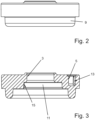
- FIG. 2 A side view of the base part 1 according to the invention is shown. From this side view, the disc-shaped basic structure of the base part 1 becomes clear. On the underside of the base part 1 (bottom in the Figure 2 ) the bead 9 is clearly visible. The bead 9 serves as a welding or material addition for friction welding. If the If the base part 1 is to be connected to a component not shown by friction welding, the base part 1 is set in rotation and at the same time pressed against the component with the bead 9. The frictional heat generated in this process causes the material of the bead 9 to become at least partially soft and plastic. As soon as this process has progressed far enough, the rotation is stopped and the base part with its liquefied/plasticized bead 9 is pressed against the component until the material of the bead 9 has become solid again.
- the base part 1 is shown in section. In this illustration, the central opening 3 and one of the three recesses 5 are clearly visible. A small rib 13 is formed in the recess 5. It serves to produce a press fit with a pin (not shown) of a tool for joining. Then the connecting element according to the invention (base part 1) and the functional part (not shown) no longer fall out of the tool until it has been joined to the component.
- the recess 11 on the underside of the base part 1 is clearly visible.
- the recess 11 has a, as can be seen particularly clearly from the Figure 4 results in a circular basic shape and has a flattened portion 15 on the right-hand side; it is therefore not rotationally symmetrical.
- This flattened portion 15 serves to create a rotationally fixed, positive connection with the head of a functional part (not shown).
- the dimensions of the bead 9, in particular its height, width, diameter and cross-section, determine the available welding allowance and parameters of the friction welding process.
- the dimensions of the bead 9 can be adapted according to the requirements of the application. This also shows the good adaptability of the connecting element according to the invention to different applications.
- the bead 9 is relatively large, so that a lot of material is available for friction welding.
- the base part 1 is shown in a view from below. This view shows the shape of the recess 11 with the flattening 15 particularly well.
- the outer contour of the base part 1 is shown in the Figure 4 marked 17.
- FIG. 5 shows a view from above of a first embodiment of a functional part 19.
- the functional part 19 comprises a head 21, a centering section 23 and a shaft 25.
- the head 21 is, as can be seen from the view from above ( Figure 5 ) is particularly easy to see, circular in shape and has a flattened portion 27.
- the head 21 and the flattened portion 27 are designed to be complementary to the recess 11 with the flattened portion 15 on the underside of the base part 1, so that a positive, rotationally fixed connection is created between the head 21 of the functional part 19 and the base part 1 when the shaft 25 is pushed from below through the opening 3 of the base part 1 until the head 21 rests against the base part 1.
- the functional part 19 comprises an (optional) centering section 23, the dimensions of which are matched to the diameter of the opening 3 of the base part 1.
- a slight press fit is preferably created between the centering section 23 and the opening 3 of the base part 1. This prevents the functional part 19 from accidentally falling out of the base part 1.
- the flattened areas 15 and 27 in the recess 11 and the head 21 respectively ensure a safe and efficient transmission of torque between the functional part 19 and the base part 1.
- the torque transmission is not limited to the embodiments shown. Large axial forces can also be transmitted between the functional part 19 and the base part 1 via the head 21.
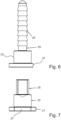
- the shaft 25 of the functional part 19 is designed as part of a snap connection. It comprises several undercuts 29, which together with corresponding locking hooks or snap hooks of a counterpart (not shown) form the aforementioned snap connection.
- FIG 7 An alternative functional part 19 is designed as an example.
- the shaft 25 has an internal thread.
- the centering section 23 and head 21 are identical in construction to the embodiment according to Figure 6 This has the advantage that the functional parts 19 can be alternatively integrated into the same base part 1 according to the Figures 6 and 7 can be used. This does not change the friction welding process for connecting the base part 1 to a component.
- the two-part design also makes it possible to combine a large number of other (not shown) functional parts 19 with the same base part. There are hardly any limits to the design freedom for the functional parts 19. It is also possible to manufacture the functional part 19 from a different material than the base part 1.
- the connecting element 31 is designed in two parts. As already mentioned, it comprises a base part 1 and a functional part 19. A slight press fit between the opening 3 and the centering section 23 ensures that the functional part 19 does not fall out of the base part 1.
- the two-part connecting element according to the invention can now be placed on a joining tool and then connected to a component by friction welding in the manner described above.
- the connecting element is in accordance with Figure 8 which is connected to a composite material component 30 by friction welding.
- the bead 9 is significantly flatter and wider. This is a result of the plasticization and deformation of the bead 9 that takes place during friction welding.
- the joining surface between the component 30 and the base part 1 of the connecting element is much larger than the cross-sectional area of the bead 9 before friction welding. This means that the load-bearing capacity of the connection is very high.
- the joining surface can be adapted to the requirements of the individual case within very wide limits by the dimensions and design of the bead 9.
- a tool 31 for joining comprises a tubular base body 33 which receives the shaft 25 of the connecting element.
- a first end 35 of the tool 31 is designed as a contact surface 36 for the base part 1.
- Three pins 37 are pressed into the front side of the tool 31, two of which are visible. These pins 37 move into the recesses 5 of the base part 1 according to Figure 1a and thereby cause a positive connection suitable for transferring the torque required for friction welding from the tool to the connecting element.
- a drive element 39 is present at an end opposite the first end 35.
- the drive element 39 is a cylindrical pin with two parallel surfaces for clamping in the tool holder.
- the tool 31 is clamped with it in a device for friction welding.
Landscapes
- Engineering & Computer Science (AREA)
- Mechanical Engineering (AREA)
- General Engineering & Computer Science (AREA)
- Lining Or Joining Of Plastics Or The Like (AREA)
- Standing Axle, Rod, Or Tube Structures Coupled By Welding, Adhesion, Or Deposition (AREA)
- Pressure Welding/Diffusion-Bonding (AREA)
- Connection Of Plates (AREA)
Description
- Die Erfindung betrifft ein Verbindungselement, insbesondere einen thermischen Stoffschlussdom, zum Befestigen an der Oberfläche eines Bauteils aus einem faserverstärkten Verbund-Werkstoff, wie zum Beispiel CFK oder GFK).
- Solche Verbindungselemente werden benötigt, um beispielsweise auf gewichtsoptimierten Bauteilen aus CFK Anbauteile zu befestigen oder mit anderen Teilen zu verbinden. Bei Bauteilen aus Faserverbundwerkstoffen ist es in vielen Fällen unerwünscht oder sogar ausgeschlossen, das Bauteil zu durchbohren, um einen Niet oder eine Schraube durch das Bauteil zu führen und das Verbindungselement auf diese Weise bekannte und vielfach bewährte Weise mit dem Bauteil zu verbinden. Diese Restriktion geht auf die Tatsache zurück, dass jede Bohrung den Faserverlauf innerhalb des Bauteils aus einem faserverstärkten Verbund-Werkstoff (Verbund-Werkstoff-Bauteil) stört und dessen Belastbarkeit verringert. Darüber hinaus kann es durch unsachgemäßes Einbringen einer Bohrung zu einer Delamination kommen.
- Um diese Nachteile zu vermeiden, hat man in der Vergangenheit solche Verbindungselemente auf die Oberfläche des CFK-Bauteils geklebt. Diese Befestigungstechnik hat jedoch verschiedene Nachteile. Nachteilig sind insbesondere die für eine automatisierte Serienfertigung lange Aushärtezeit des Klebstoffs und die Schwierigkeiten eine solche Klebverbindung prozesssicher herzustellen.
- Aus der
EP 0 337 813 A1 ist ein reibschweißbarer zweiteiliger Bolzen bekannt. Er besteht aus einem Schaft und einen Kragen. Aus derDE 20 2004 014071 U1 und derEP 3 259 093 A1 337 813 A1 - Der Erfindung liegt die Aufgabe zugrunde, ein Verbindungselement bereitzustellen, das die Nachteile des Standes der Technik vermeidet. Es soll prozesssicher und automatisierbar mit dem Bauteil verbindbar sein, ohne dass das Bauteil eine Bohrung benötigt. Darüber hinaus soll es nicht nur kostengünstig sein, sondern auch flexibel an verschiedene Aufgabenstellungen/Befestigungsaufgaben adaptierbar sein.
- Diese Aufgabe wird erfindungsgemäß gelöst durch ein Verbindungselement, insbesondere einen thermischen Stoffschlussdom, zum Befestigen an der Oberfläche eines Bauteils durch Reibschweißen umfassend ein Grundteil und ein Funktionsteil, wobei das Grundteil eine Oberseite und eine der Oberseite gegenüberliegende Unterseite mit einem ringförmigen Wulst aufweist, wobei das Grundteil eine die Oberseite und die Unterseite verbindende Öffnung aufweist, und wobei das Funktionsteil einen Schaft und an einem ersten Ende des Schafts einen Kopf aufweist, dessen Durchmesser oder Erstreckung quer zu einer Längsachse des Schafts größer als ein Durchmesser der Öffnung im Grundteil ist.
- Das erfindungsgemäße Verbindungselement ist also zweiteilig. Es umfasst ein Grundteil, das an seiner Unterseite einen Wulst aufweist. Der Wulst "liefert" die Schweißzugabe beim Reibschweißen. Außerdem können durch eine entsprechende Gestaltung (vor allem Durchmesser, Breite, Höhe und Querschnittsform) der Reibschweißvorgang und die Festigkeit der Reibschweißverbindung einfach und flexibel an das Verbund-Werkstoff-Bauteil und die Befestigungsaufgabe angepasst werden.
- Des Weiteren umfasst das erfindungsgemäße Verbindungselement ein Funktionsteil, das mit seinem Schaft von unten durch die Öffnung im Grundteil gesteckt wird, bis der Kopf des Funktionsteils an der Unterseite des Grundteils anliegt. Dann können Zugkräfte zwischen Funktionsteil und Grundteil übertragen werden. Sobald das Grundteil mit seinem Wulst an einem Bauteil durch Reibschweißen stoffschlüssig befestigt wurde, ist das Funktionsteil mittelbar aber dennoch fest mit dem Bauteil verbunden. Falls gewünscht, kann auch eine drehfeste formschlüssige Verbindung zwischen Funktionsteil und Grundteil ohne Weiteres hergestellt werden.
- Durch die zweiteilige Bauweise ist es möglich, verschiedene Funktionsteile mit baugleichen Grundteilen zu kombinieren, so dass mit Hilfe des Funktionsteils beispielsweise eine Schnappverbindung, eine Schraubverbindung mittels Innengewinde oder Außengewinde herzustellen, ohne irgendeine Änderung am Grundteil und dem erfindungsgemäßen Fügevorgang. Beispielsweise können an einem Bauteil ein Befestigungselement mit einer Schnappverbindung und ein Befestigungselement mit einem Innengewinde mit der gleichen Vorrichtung zum Reibschweißen ohne Änderungen an den Prozessparametern befestigt werden, indem das baugleiche Grundteile mit verschiedenen Funktionsteilen kombiniert und der Vorrichtung zum Reibschweißen zugeführt werden. Das ist für die prozesssichere Serienfertigung von leistungsfähigen Leichtbauteilen ein erheblicher Vorteil.
- Das erfindungsgemäße Verbindungselement ist sehr kostengünstig, da die Werkstoffe beider Bauteile (Grundteil und Funktionsteil) der jeweiligen Aufgabe entsprechend optimiert werden können. Das Grundteil ist, in vielen Fällen aus einem thermoplastischen Kunststoff. Bevorzugt aus einem faserverstärkten thermoplastischen Kunststoff, wie beispielsweise PA 66 35 GF. Selbstverständlich können auch andere (thermoplastische) Kunststoffe - mit und ohne Faserverstärkung - eingesetzt werden. Besonders geeignet sind: Polyphenylensulfid (PPS), Poyamid 6 (PA 6) und Polypropylen mit 30 % Glasfaser (PP GF30).
- Das erfindungsgemäße Verbindungselement kann jedoch auch aus einem schweißbaren metallischen Werkstoff hergestellt werden.
- Dann kann das Verbindungselement mit einem metallischen Bauteil durch Reibschweißen verbunden werden. Dabei müssen das Bauteil und das Grundteil miteinander verschweißbar sein. Da das Funktionsteil lediglich formschlüssig und nicht stoffschlüssig mit dem Verbindungsteil verbunden ist, bestehen bezüglich des Materials des Funktionsteils keine Restriktionen.
- Diese nicht abschließenden Beispiele zeigen die große Flexibilität und Anpassbarkeit des erfindungsgemäßen Verbindungselements an verschiedenste Anforderungsprofile.
- Erfindungsgemäße ist vorgesehen, dass an der Oberseite und/oder der Außenkontur des Grundteils mindestens ein Formschlusselement ausgebildet ist, und dass das mindestens eine Formschlusselement zum Übertragen des beim Reibschweißen erforderlichen Drehmoments von einem Werkzeug zum Fügen auf das Grundteil ausgebildet ist.
- Das oder die Formschlusselemente können beispielsweise eine oder mehrere bevorzugte kreisrunde Vertiefungen (Sacklöcher) in der Oberseite des Grundteils umfassen. Es ist auch möglich, die Formschlusselemente als Längsnuten oder Vertiefungen an der Außenkontur des Grundteils auszubilden. Selbstverständlich ist es auch möglich, das Grundteil mit einer nicht rotationssymmetrischen Geometrieaußenkontur, wie beispielsweise einem Polygon (Dreieck, Viereck, Fünfeck, Sechseck, ...) oder als Gleichdick auszubilden, so dass das zum Reibschweißen erforderliche Drehmoment über die Außenkontur in das Grundteil eingeleitet werden kann. Dadurch ergeben sich glattflächige Verbindungselemente.
- Durch die Vielzahl möglicher Formschlusselemente ist das Design des Grundteils kaum Restriktionen unterworfen. Vielmehr können auch gestalterische Belange berücksichtigt werden und ein ansprechendes Design erreicht werden.
- Beispielsweise in Anwendungen wo großer Wert auf Sauberkeit gelegt wird, ist eine glattflächige Außenkontur des Grundteils, ohne Vertiefungen oder Nuten möglicherweise besonders vorteilhaft. Dann kann die Außenkontur des Grundteils ein Polygon oder Gleichdick sein. Sacklöcher und Nuten an der Außenkontur können dann entfallen.
- Um eine gute und belastbare Übertragung von Zugkräften von dem Schaft des Funktionsteils auf das Grundteil zu gewährleisten, ist der Kopf des Funktionsteils als Platte, bevorzugt als nicht-rotationssymmetrische Platte ausgebildet. Wenn die Platte nicht rotationssymmetrisch ist und auf der Unterseite des Grundteils eine entsprechende Vertiefung ausgebildet ist, können auch Drehmomente zwischen Grundteil und Funktionsteil übertragen werden. Das ist häufig dann vorteilhaft, wenn das Funktionsteil ein Außen- oder Innengewinde an seinem Schaft aufweist und eine Schraube beziehungsweise Mutter auf das Funktionsteil aufgedreht werden soll. Die Abmessungen des Kopfs werden entsprechend dem Lastkollektiv (Axialkräfte, Drehmomente) denen das Verbindungselement ausgesetzt ist, bestimmt. erwartenden Axialkräften gewählt werden.
- Das Funktionsteil kann optional einen mit der Öffnung im Grundteil des Gehäuses zusammenwirkenden Zentrierabschnitt aufweisen. Dann wird das Funktionsteil über den Zentrierabschnitt in der Öffnung des Grundteils zentriert. Es ist auch möglich hier einen Schiebesitz oder eine leichte Presspassung vorzusehen, so dass, wenn das Funktionsteil mit seinem Zentrierabschnitt in die Öffnung des Grundteils einpresst wurde, die beiden Bauteile des erfindungsgemäßen Verbindungselements miteinander verbunden sind. Das erleichtert die Handhabung (manuell oder automatisiert) des erfindungsgemäßen Verbindungselements vor dem Verschweißen des Grundteils mit dem Bauteil.
- Entsprechend den Anforderungen des Anwendungsfalls kann der Schaft des Funktionsteils Teil einer Schnappverbindung sein. Er kann jedoch auch ein Außengewinde oder ein Innengewinde aufweisen. Auch sind Querbohrungen zur Aufnahme eines Splints oder eine Nut zur Aufnahme eines Sicherungsrings (Seeger-Ring) ausgebildet sein. Es können auch Widerhaken an dem Schaft angeordnet sein, mit deren Hilfe weiche Materialien an dem Schaft fixiert werden. Der Schaft kann so gestaltet werden, dass er optimal mit einem oder mehreren Bauteilen verbindbar ist. Der Gestaltung des Schafts sind keine Grenzen gesetzt.
- Ein Werkzeug zum Fügen des Verbindungselements mit einem Bauteilweist einen mindestens bereichsweise hohlen oder rohrförmigen Werkzeugkörper auf, dessen erstes Ende so ausgebildet ist, dass es eine drehfeste formschlüssige Verbindung mit dem Grundteil und/oder dem Zentrierabschnitt des Funktionsteils eingeht, wenn es auf dem Verbindungsteil aufgesetzt ist. Der Hohlraum/die Mittenbohrung im Werkzeugkörper dient dazu, den Schaft des Funktionsteils aufzunehmen.
- Das erste Ende des Werkzeugs ist komplementär zu der Oberseite beziehungsweise der Außenkontur des Grundteils ausgestaltet. Wenn, wie beispielsweise in der
Figur 1 , dargestellt, in der Oberseite des Grundteils Vertiefungen ausgebildet sind, dann weist das erste Ende des Werkzeugs drei Zapfen auf, die in die Vertiefungen einfahren, wenn das Werkzeug auf das Grundteil aufgesetzt wird. Es sind eine Vielzahl anderer Ausgestaltungen möglich. Wichtig ist jedoch, dass durch die komplementäre Gestaltung des ersten Endes des Werkzeugs und des Grundteils das zum Reibschweißen erforderliche Drehmoment während des Reibschweißvorgangs von dem Werkzeug auf das Grundteil übertragen wird und damit das erfindungsgemäße Verbindungselement mit dem Bauteil verbunden wird. - Weitere Vorteile und vorteilhafte Ausgestaltungen der Erfindung sind der nachfolgenden Zeichnung, deren Beschreibung und den Patentansprüchen entnehmenbar. Alle in der Zeichnung, deren Beschreibung und den Patentansprüchen offenbarten Merkmale können sowohl einzeln als auch in beliebiger Kombination miteinander erfindungswesentlich sein.
- Es zeigen:
- Figur 1
- eine Ansicht von oben auf ein Grundteil eines erfindungsgemäßen Verbindungselements,
- Figur 2
- eine Seitenansicht des Grundteils,
- Figur 3
- einen Schnitt durch das erfindungsgemäße Grundteil,
- Figur 4
- eine Ansicht von unten eines erfindungsgemäßen Grundteils,
- Figuren 5 bis 7
- verschiedene Darstellungen erfindungsgemäßer Funktionsteile,
- Figur 8
- das erfindungsgemäße zweiteilige Verbindungselement mit Grundteil und Funktionsteil teilweise geschnitten;
- Figur 9
- ein mit einem Bauteil verschweißtes zweiteilige Verbindungselement; und
- Figur 10
- ein Ausführungsbeispiel eines Werkzeugs zum Fügen des Verbindungselements mit einem Bauteil.
- In der
Figur 1a ist eine Ansicht von oben auf das Grundteil 1 eines erfindungsgemäßen Verbindungselements dargestellt. Bei diesem Ausführungsbeispiel ist das Grundteil 1 als im Wesentlichen kreisförmige Scheibe oder Platte ausgebildet. Es weist in der Mitte eine Öffnung 3 auf. An der Oberseite des Grundteils 1 sind drei über den Umfang verteilte kreisförmige Vertiefungen 5 angeordnet. Sie sind Sacklöcher, die dazu dienen, mit entsprechenden komplementär gestalteten und angeordneten Zapfen eines Werkzeugs (sieheFigur 9 ) das zum Reibschweißen erforderliche Drehmoment von dem Werkzeug auf das Grundteil 1 zu übertragen. - In der
Figur 1b ist eine weitere Alternative der Drehmomentübertragung zwischen einem Werkzeug zum Reibschweißen und dem Grundteil 1 zeichnerisch dargestellt: An der kreisförmigen Außenkontur sind drei Längsnuten oder Vertiefungen 7 angeordnet. Die Vertiefungen 7 können mit entsprechenden Rippen oder Zapfen an einem Werkzeug zum Reibschweißen einen Formschluss bilden und dadurch das erforderliche Drehmoment von dem Werkzeug auf das Grundteil 1 übertragen. Die Vertiefungen 5 gemäß dem ersten Ausführungsbeispiel können dann entfallen. - Es ist nicht notwendig, sowohl die Vertiefungen 5 als auch die Nuten 7 an einem Grundteil auszubilden. In der Regel ist eines der Elemente 5 oder 7 ausreichend. Das Grundteil 1 kann sowohl über die Längsnuten 7 als auch über die Vertiefungen 5 relativ zu dem Werkzeug zentriert werden. Es ist jedoch auch möglich, die Zentrierung des Grundteils 1 relativ zu dem Werkzeug beispielswiese über die Außenkontur des Grundteils 1 und eine komplementäre Gestaltung des Werkzeugs zu erreichen.
- Es ist auch möglich, das Grundteil 1 nicht kreisrund auszubilden, sondern beispielsweise als Sechseck oder als Gleichdick (Polygon) auszubilden. Dann ist die Außenkontur nicht rotationssymmetrisch und es ist möglich mit Hilfe eines komplementär geformten Werkzeugs das Drehmoment vom Werkzeug auf das Grundteil zu übertragen. In diesem Fall sind dann weder Vertiefungen 5, noch Längsnuten 7 erforderlich. Dadurch ergibt sich eine besonders glatte und wenig verschmutzungsanfällige Außenkontur des Grundteils 1. Diese Ausführungsform ist nicht dargestellt.
- Die unterbrochenen kreisförmigen Linien in den
Figuren 1a und1b zeigen einen Wulst 9 sowie eine Vertiefung 11 an der Unterseite des Grundteils 1. Form und Funktion des Wulstes 9 und der Ausnehmung 11 werden nachfolgend im Zusammenhang mit denFiguren 3 und4 näher erläutert. - In der
Figur 2 ist eine Seitenansicht des erfindungsgemäßen Grundteils 1 dargestellt. Aus dieser Seitenansicht wird der scheibenförmige Grundaufbau des Grundteils 1 deutlich. An der Unterseite des Grundteils 1 (unten in derFigur 2 ) ist der Wulst 9 gut zu erkennen. Der Wulst 9 dient als Schweiß- oder Materialzugabe für das Reibschweißen. Wenn nämlich das Grundteil 1 mit einem nicht dargestellten Bauteil durch Reibschweißen verbunden werden soll, dann wird das Grundteil 1 in Rotation versetzt und gleichzeitig mit dem Wulst 9 gegen das Bauteil gedrückt. Durch die dabei entstehende Reibungswärme wird das Material des Wulstes 9 zumindest teilweise weich und plastisch. Sobald dieser Prozess weit genug fortgeschritten ist, wird die Rotation beendet und das Grundteil mit seinem verflüssigten/plastifizierten Wulst 9 gegen das Bauteil gepresst, bis das Material des Wulstes 9 wieder fest geworden ist. - In der
Figur 3 ist das Grundteil 1 geschnitten dargestellt. In dieser Darstellung sind die zentrale Öffnung 3 und eine der drei Vertiefungen 5 gut zu erkennen. In der Vertiefung 5 ist eine kleine Rippe 13 ausgebildet. Sie dient dazu, einen Presssitz mit einem Zapfen (nicht dargestellt) eines Werkzeugs zum Fügen herzustellen. Dann fallen das erfindungsgemäße Verbindungselement (Grundteil 1) und das nicht dargestellte Funktionsteil nicht mehr aus dem Werkzeug heraus, bis es mit dem Bauteil gefügt wurde. - In der
Figur 3 ist die Ausnehmung 11 an der Unterseite des Grundteils 1 gut zu erkennen. Die Ausnehmung 11 hat eine, wie sich besonders anschaulich aus derFigur 4 ergibt, eine kreisförmige Grundform und weist an der rechten Seite eine Abflachung 15 auf; sie ist also nicht rotationssymmetrisch. Diese Abflachung 15 dient dazu, eine drehfeste formschlüssige Verbindung mit dem Kopf eines nicht dargestellten Funktionsteils herbeizuführen. - Die Abmessungen des Wulstes 9, insbesondere dessen Höhe, Breite, Durchmesser und Querschnitt, bestimmen die zur Verfügung stehenden Schweißzugabe und Parameter des Reibschweißvorgangs. Die Abmessungen des Wulstes 9 können entsprechend den Anforderungen des Anwendungsfalls angepasst werden. Auch hier zeigt sich die gute Adaptierbarkeit des erfindungsgemäßen Verbindungselements an verschiedene Anwendungsfälle.
- In dem dargestellten Ausführungsbeispiel ist der Wulst 9 relativ groß, so dass sehr viel Material zum Reibschweißen zur Verfügung steht.
- In der
Figur 4 ist das Grundteil 1 in einer Ansicht von unten dargestellt. Aus dieser Ansicht ergibt sich besonders gut die Form der Ausnehmung 11 mit der Abflachung 15. Die Außenkontur des Grundteils 1 ist in derFigur 4 mit 17 bezeichnet. - In den
Figuren 5 bis 7 sind verschiedene Ansichten von zwei Ausführungsbeispielen erfindungsgemäßer Funktionsteile 19 dargestellt. DieFigur 5 zeigt eine Ansicht von oben auf ein erstes Ausführungsbeispiel eines Funktionsteil 19. Wie sich aus denFiguren 5 bis 7 ergibt, umfasst das Funktionsteil 19 bei allen Ausführungsbeispielen einen Kopf 21, einen Zentrierabschnitt 23 und einen Schaft 25. - Der Kopf 21 ist, wie sich aus der Ansicht von oben (
Figur 5 ) besonders gut erkennen lässt, kreisförmig ausgebildet und weist eine Abflachung 27 auf. Der Kopf 21 und die Abflachung 27 sind komplementär zu der Ausnehmung 11 mit der Abflachung 15 auf der Unterseite des Grundteils 1 ausgebildet, so dass eine formschlüssige drehfeste Verbindung zwischen dem Kopf 21 des Funktionsteils 19 und dem Grundteil 1 entsteht, wenn der Schaft 25 von unten durch die Öffnung 3 des Grundteils 1 geschoben wird, bis der Kopf 21 an dem Grundteil 1 anliegt. - Bei den dargestellten Ausführungsbeispielen umfasst das Funktionsteil 19 einen (optionalen) Zentrierabschnitt 23, der in seinen Abmessungen auf den Durchmesser der Öffnung 3 des Grundteils 1 abgestimmt ist. Wenn das Funktionsteil mit dem Schaft 25 durch die Öffnung in das Grundteil geschoben wird, entsteht bevorzugt ein leichter Presssitz zwischen dem Zentrierabschnitt 23 und der Öffnung 3 des Grundteils 1. Er verhindert, dass das Funktionsteil 19 unbeabsichtigter Weise wieder aus dem Grundteil 1 herausfällt.
- Durch die Abflachungen 15 beziehungsweise 27 in der Ausnehmung 11 beziehungsweise dem Kopf 21 ist eine sichere und leistungsfähige Übertragung von Drehmomenten zwischen Funktionsteil 19 und Grundteil 1 gewährleistet. Die Drehmomentübertragung ist nicht auf die dargestellten Ausführungsbeispiele beschränkt. Über den Kopf 21 können auch große axiale Kräfte zwischen dem Funktionsteil 19 und dem Grundteil 1 übertragen werden.
- In der
Figur 6 ist der Schaft 25 des Funktionsteils 19 als Teil einer Schnappverbindung ausgebildet. Er umfasst mehrere Hinterschnitte 29, die zusammen mit entsprechenden Rasthaken oder Schnapphaken eines nicht dargestellten Gegenstücks die erwähnte Schnappverbindung bilden. - In der
Figur 7 ist beispielhaft ein alternatives Funktionsteil 19 ausgebildet. Dabei weist der Schaft 25 ein Innengewinde auf. Zentrierabschnitt 23 und Kopf 21 sind baugleich wie bei dem Ausführungsbeispiel gemäßFigur 6 ausgeführt. Dies hat den Vorteil, dass in das gleiche Grundteil 1 alternativ die Funktionsteile 19 gemäß derFiguren 6 und 7 eingesetzt werden können. An dem Reibschweißprozess zum Verbinden des Grundteils 1 mit einem Bauteil ändert sich dadurch nichts. Es ist durch die zweiteilige Bauweise auch möglich, eine Vielzahl weiterer (nicht dargestellter) Funktionsteile 19 mit dem gleichen Grundteil zu kombinieren. Der Gestaltungsfreiheit bei den Funktionsteilen 19 sind kaum Grenzen gesetzt. Auch ist es möglich, das Funktionsteil 19 aus einem anderen Material herzustellen als das Grundteil 1. - In der
Figur 8 ist eine Zusammenbauzeichnung des erfindungsgemäßen Verbindungselements dargestellt. Das Verbindungselement 31 ist zweiteilig ausgeführt. Es umfasst, wie bereits erwähnt, ein Grundteil 1 und ein Funktionsteil 19. Durch einen leichten Presssitz zwischen der Öffnung 3 und dem Zentrierabschnitt 23 kann erreicht werden, dass das Funktionsteil 19 nicht aus dem Grundteil 1 herausfällt. - Das erfindungsgemäße zweiteilige Verbindungselement kann nun auf ein Werkzeug zum Fügen aufgesetzt werden und dann mit einem Bauteil durch Reibschweißen in der oben beschriebenen Art und Weise verbunden werden.
- In der
Figur 9 ist das Verbindungselement gemäßFigur 8 dargestellt, das mit einem Verbund-Werkstoff-Bauteil 30 durch Reibschweißen verbunden ist. Der Wulst 9 ist deutlich flacher und breiter. Das ist eine Folge der beim Reibschweißen stattfindenden Plastifizierung und Verformung des Wulsts 9. Die Fügefläche zwischen dem Bauteil 30 und dem Grundteil 1 des Verbindungselements ist sehr viel größer als die Querschnittsfläche des Wulsts 9 vor dem Reibschweißen. Dadurch ist die Belastbarkeit der Verbindung sehr groß. Die Fügefläche kann, wie bereits erwähnt, durch die Abmessungen und Gestaltung des Wulsts 9 in sehr weiten Grenzen an die Anforderungen des Einzelfalls angepasst werden. - In der
Figur 10 ist ein Ausführungsbeispiel eines Werkzeugs 31 zum Fügen dargestellt. Es umfasst einen rohrförmigen Grundkörper 33, der den Schaft 25 des Verbindungselements aufnimmt. - Ein erstes Ende 35 des Werkzeugs 31 ist als Anlagefläche 36 für das Grundteil 1 ausgebildet. An der Stirnseite des Werkzeugs 31 sind drei Zapfen 37 eingepresst von denen zwei sichtbar sind. Diese Zapfen 37 fahren in die Vertiefungen 5 des Grundteils 1 gemäß
Figur 1a ein und bewirken dadurch eine formschlüssige Verbindung, die geeignet ist, um das zum Reibschweißen erforderliche Drehmoment von dem Werkzeug auf das Verbindungselement zu übertragen. - An einem dem ersten Ende 35 gegenüberliegenden Ende ist ein Antriebselement 39 vorhanden. Das Antriebselement 39 ist bei dem dargestellten Ausführungsbeispiel ein zylindrischer Zapfen mit zwei parallelen Flächen für die Verspannung in der Werkzeugaufnahme. Mit ihm wird das Werkzeug 31 in eine Vorrichtung zum Reibschweißen eingespannt.
-
- 1
- Grundteil
- 3
- Öffnung
- 5
- Vertiefung
- 7
- Längsnut
- 9
- Wulst
- 11
- Vertiefung/Ausnehmung
- 13
- Rippe
- 15
- Abflachung
- 17
- Außenkontur
- 19
- Funktionsteil
- 21
- Kopf
- 23
- Zentrierabschnitt
- 25
- Schaft
- 27
- Abflachung
- 29
- Hinterschnitt
- 30
- Bauteil
- 31
- Werkzeug
- 33
- Rohrförmiger Grundkörper
- 35
- erstes Ende
- 37
- Zapfen
- 39
- Antriebselement
- 41
- Innengewinde
Claims (12)
- Verbindungselement, insbesondere thermischer Stoffschlussdom, zum Befestigen an der Oberfläche eines Bauteils (30) durch Reibschweißen umfassend ein Grundteil (1) und ein Funktionsteil (19), wobei das Grundteil (1) eine Oberseite und eine der Oberseite gegenüberliegende Unterseite mit einem ringförmigen Wulst (9) aufweist, wobei das Grundteil (1) eine die Oberseite und die Unterseite verbindende Öffnung (3) aufweist, und wobei das Funktionsteil (19) einen Schaft (25) und an einem ersten Ende des Schafts (25) einen Kopf (21) aufweist, dessen Durchmesser oder Erstreckung quer zu einer Längsachse des Schafts (25) größer als ein Durchmesser der Öffnung (3) ist.
- Verbindungselement nach Anspruch 1, dadurch gekennzeichnet, dass das Grundteil (1) an der Oberseite und/oder der Außenkontur (17) mindestens ein Formschlusselement aufweist, und dass das mindestens eine Formschlusselement zum Übertragen des beim Reibschweißen erforderlichen Drehmoments von einem Werkzeug (31) zum Fügen auf das Grundteil (1) ausgebildet ist.
- Verbindungselement nach Anspruch 2, dadurch gekennzeichnet, dass das Formschlusselement eine oder mehrere, bevorzugt kreisrunde Vertiefungen (5) in der Oberseite des Grundteils (1) umfasst.
- Verbindungselement nach Anspruch 2, dadurch gekennzeichnet, dass das Formschlusselement eine, zwei, drei oder mehr Längsnuten (7) oder -vertiefungen an der Außenkontur (17) des Grundteils (1) umfasst.
- Verbindungselement nach Anspruch 2, dadurch gekennzeichnet, dass das eine Formschlusselement eine nicht rotationssymmetrische Außenkontur (17), insbesondere in Form eines regelmäßigen oder unregelmäßigen Polygons oder Gleichdicks umfasst.
- Verbindungselement nach einem der vorherigen Ansprüche, dadurch gekennzeichnet, dass der Kopf (21) des Funktionsteils (10) als Platte, bevorzugt als nicht rotationssymmetrische Platte ausgebildet ist.
- Verbindungselement nach einem der vorherigen Ansprüche, dadurch gekennzeichnet, dass die Unterseite des Grundteils (1) komplementär zu dem Kopf (21) des Funktionsteils (19) ausgebildet ist, so dass das Funktionsteil (19) und das Grundteil (1) drehfest und formschlüssig miteinander verbunden sind.
- Verbindungselement nach einem der vorherigen Ansprüche, dadurch gekennzeichnet, dass das Funktionsteil (19) einen mit der Öffnung (3) im Grundteil (1) zusammenwirkenden Zentrierabschnitt (23) aufweist.
- Verbindungselement nach einem der vorherigen Ansprüche, dadurch gekennzeichnet, dass die Öffnung (3) des Grundteils (1) und der Zentrierabschnitt (23) des Funktionsteils (19) drehfest und formschlüssig miteinander verbunden sind.
- Verbindungselement nach einem der vorherigen Ansprüche, dadurch gekennzeichnet, dass der Schaft (25) des Funktionsteils (19) als Teil einer Schnappverbindung mit einem oder mehreren Hinterschnitten (29) ausgebildet ist.
- Verbindungselement nach einem Ansprüche 1 bis 9, dadurch gekennzeichnet, dass an dem Schaft (25) des Funktionsteils (1) ein Außen-Gewinde und/oder oder ein Innengewinde (41) ausgebildet ist.
- Verbindungselement (10) nach einem der vorherigen Ansprüche, dadurch gekennzeichnet, dass das Grundteil (1) aus einem schweißbaren Material, insbesondere einem thermoplastischen Kunststoff oder Metall, hergestellt ist.
Applications Claiming Priority (2)
| Application Number | Priority Date | Filing Date | Title |
|---|---|---|---|
| DE102019135240.1A DE102019135240A1 (de) | 2019-12-19 | 2019-12-19 | Verbindungselement und Werkzeug zum Befestigen eines Verbindungselements auf einem Bauteil durch Reibschweißen |
| PCT/EP2020/084435 WO2021122031A1 (de) | 2019-12-19 | 2020-12-03 | VERBINDUNGSELEMENT UND WERKZEUG ZUM BEFESTIGEN EINES VERBINDUNGSELEMENTS AUF EINEM BAUTEIL DURCH REIBSCHWEIßEN |
Publications (2)
| Publication Number | Publication Date |
|---|---|
| EP4077953A1 EP4077953A1 (de) | 2022-10-26 |
| EP4077953B1 true EP4077953B1 (de) | 2024-11-06 |
Family
ID=73726814
Family Applications (1)
| Application Number | Title | Priority Date | Filing Date |
|---|---|---|---|
| EP20820106.1A Active EP4077953B1 (de) | 2019-12-19 | 2020-12-03 | Verbindungselement zum befestigen auf einem bauteil durch reibschweissen |
Country Status (10)
| Country | Link |
|---|---|
| US (1) | US20230026191A1 (de) |
| EP (1) | EP4077953B1 (de) |
| JP (1) | JP7703539B2 (de) |
| KR (1) | KR102889132B1 (de) |
| CN (1) | CN114930035A (de) |
| BR (1) | BR112022011928A2 (de) |
| CA (1) | CA3160744A1 (de) |
| DE (1) | DE102019135240A1 (de) |
| MX (1) | MX2022007537A (de) |
| WO (1) | WO2021122031A1 (de) |
Families Citing this family (2)
| Publication number | Priority date | Publication date | Assignee | Title |
|---|---|---|---|---|
| JP6567417B2 (ja) | 2012-10-01 | 2019-08-28 | ラトガーズ, ザ ステイト ユニバーシティ オブ ニュー ジャージー | 水熱液相焼結(hlps)のための前駆体および輸送方法 |
| CN118492600B (zh) * | 2024-06-21 | 2025-01-24 | 哈尔滨工业大学 | 一种低应力高强度铝-镁接头的搅拌摩擦焊接装置及方法 |
Family Cites Families (16)
| Publication number | Priority date | Publication date | Assignee | Title |
|---|---|---|---|---|
| DE7907821U1 (de) * | 1979-07-26 | Karl Limbach & Cie. Kg., 5650 Solingen | An schweißmutter | |
| US3377009A (en) * | 1965-04-23 | 1968-04-09 | Caterpillar Tractor Co | Bonding machines |
| US3444018A (en) * | 1966-02-25 | 1969-05-13 | Uniroyal Inc | Method of mounting fastening elements on thermoplastic materials by friction welding |
| US4599768A (en) * | 1985-05-13 | 1986-07-15 | Illinois Tool Works Inc. | Spin welded fastening assembly |
| US4850772A (en) * | 1988-04-15 | 1989-07-25 | Trw Inc. | Friction-weldable stud |
| JP2002224854A (ja) | 2001-01-31 | 2002-08-13 | Izumi Kogyo Kk | 摩擦圧接方法及び摩擦圧接装置 |
| DE202004014071U1 (de) * | 2004-09-09 | 2006-02-02 | Ejot Gmbh & Co. Kg | Befestigungselement zur Reibschweißverbindung mit einem flächigen Bauteil |
| KR20070031461A (ko) * | 2004-07-16 | 2007-03-19 | 에요트 게엠베하 운트 콤파니 카게 | 평탄한 부재에 마찰 용접하기 위한 체결 요소 |
| DE102007021891A1 (de) * | 2007-05-10 | 2008-11-13 | Ejot Gmbh & Co. Kg | Verfahren zur Herstellung einer Reibschweißverbindung und Gestaltung der Reibschweißverbindung |
| US8540134B2 (en) * | 2009-09-11 | 2013-09-24 | The Boeing Company | Reinforcement of friction plug welds |
| JP4838388B2 (ja) * | 2009-11-18 | 2011-12-14 | 三菱日立製鉄機械株式会社 | 両面摩擦攪拌接合方法および装置並びに両面摩擦攪拌接合用ツールセット |
| DE202012011021U1 (de) * | 2012-11-16 | 2014-02-17 | Ejot Gmbh & Co. Kg | Setzwerkzeugsytem |
| DE102013202583B3 (de) * | 2013-02-18 | 2014-07-03 | Böllhoff Verbindungstechnik GmbH | Reibschweißelement, Gehäuse und Verbindungsverfahren für das Reibschweißelement mit einem Gehäuse |
| JP5976941B2 (ja) * | 2013-08-01 | 2016-08-24 | 日立オートモティブシステムズ株式会社 | 内燃機関用ピストンの製造方法 |
| DE102015202776A1 (de) * | 2015-02-16 | 2016-08-18 | Ejot Gmbh & Co. Kg | Befestigungselement |
| DE102016125660A1 (de) * | 2016-12-23 | 2018-06-28 | Böllhoff Verbindungstechnik GmbH | Befestigungseinleger für ein Bauteil aus Kunststoff-, Schaum- oder Verbundmaterial |
-
2019
- 2019-12-19 DE DE102019135240.1A patent/DE102019135240A1/de active Pending
-
2020
- 2020-12-03 JP JP2022536667A patent/JP7703539B2/ja active Active
- 2020-12-03 MX MX2022007537A patent/MX2022007537A/es unknown
- 2020-12-03 EP EP20820106.1A patent/EP4077953B1/de active Active
- 2020-12-03 CN CN202080088315.XA patent/CN114930035A/zh active Pending
- 2020-12-03 CA CA3160744A patent/CA3160744A1/en active Pending
- 2020-12-03 BR BR112022011928A patent/BR112022011928A2/pt not_active IP Right Cessation
- 2020-12-03 KR KR1020227023781A patent/KR102889132B1/ko active Active
- 2020-12-03 US US17/785,516 patent/US20230026191A1/en active Pending
- 2020-12-03 WO PCT/EP2020/084435 patent/WO2021122031A1/de not_active Ceased
Also Published As
| Publication number | Publication date |
|---|---|
| CA3160744A1 (en) | 2021-06-24 |
| JP2023507938A (ja) | 2023-02-28 |
| MX2022007537A (es) | 2022-09-23 |
| JP7703539B2 (ja) | 2025-07-07 |
| KR20220119402A (ko) | 2022-08-29 |
| DE102019135240A1 (de) | 2021-06-24 |
| KR102889132B1 (ko) | 2025-11-20 |
| WO2021122031A1 (de) | 2021-06-24 |
| CN114930035A (zh) | 2022-08-19 |
| EP4077953A1 (de) | 2022-10-26 |
| BR112022011928A2 (pt) | 2022-09-06 |
| US20230026191A1 (en) | 2023-01-26 |
Similar Documents
| Publication | Publication Date | Title |
|---|---|---|
| EP3116705B1 (de) | Verfahren zum verbinden von bauteilen von denen eines aus einem faserverstärkten kunststoff besteht | |
| EP1918596B1 (de) | Blindnietelement sowie Verwendung hierfür | |
| DE60021730T2 (de) | Hochfester Blindbolzen über einen erweiterten Greifbereich gleichmäßig hoher Klemmkraft | |
| EP2893203B1 (de) | Loch- und gewindeformende schraube zum direktverschrauben von bauteilen ohne vorlochen, sowie hiermit hergestellter bauteilverbund | |
| EP2412991B1 (de) | Selbststanzendes Mutterelement und Zusammenbauteil bestehend aus dem Mutterelement und einem Blechteil | |
| EP2082143B1 (de) | Kombination aus einer schraube, einer unterlegscheibe und einer hülse sowie verfahren zum herstellen einer solchen kombination | |
| WO2012152755A1 (de) | Bolzen und spannsystem mit bolzen | |
| DE19815407A1 (de) | Verbindungseinrichtung zum Verbinden zweier Bauteile, Kombination der Verbindungseinrichtung mit den beiden Bauteilen und Verfahren zur Herstellung einer Verbindung zwischen zwei Bauteilen | |
| DE4410475A1 (de) | Vernietbares Element, Zusammenbauteil mit einem vernietbaren Element sowie Nietmatrize und Verfahren zur Herstellung des Zusammenbauteils | |
| DE102011001522B4 (de) | Verbindungselement zur Herstellung einer Verbindung zwischen wenigstens zwei sich überlappenden Bauteilen und Verfahren zur Herstellung dieser Verbindung | |
| WO1988005991A2 (en) | Fixing device and method for the manufacture of same | |
| EP4077953B1 (de) | Verbindungselement zum befestigen auf einem bauteil durch reibschweissen | |
| EP2484924A1 (de) | Fügeverbindung sowie Verfahren zur Ausbildung einer Fügeverbindung | |
| EP3599385B1 (de) | Kugelsperrbolzen mit kopfnaher arretierung | |
| DE19949161B4 (de) | Befestigungsanordnung zum Befestigen eines Nietelementes an einem plattenförmigen Bauteil | |
| WO2016166328A1 (de) | Verbindungselement zur formschlüssigen verbindung mit wenigstens einem bauteil | |
| DE102016209395A1 (de) | Befestigungselement für den Toleranzausgleich | |
| DE10248102B4 (de) | Verfahren zum Fügen von Stahlelementen mit einer Schraube | |
| DE10020218A1 (de) | Montageeinheit aus einem Bauteil und mindestens einer gewindeformenden Schraube | |
| EP4040927A1 (de) | Baugruppe umfassend eine platine und ein grundteil | |
| EP3631214B1 (de) | Kraftübertragungsanordnung und insert | |
| DE102009035725A1 (de) | Selbstlochender Blindniet | |
| DE1912996C3 (de) | Preßsitzverbindung von Bauteilen, insbesondere für Konstruktionen der Luftfahrtindustrie | |
| DE202006000666U1 (de) | Verbindungsanordnung zum Verbinden zweier Bauteile mittels eines Nagels | |
| EP4033113B1 (de) | Selbststanzendes funktionselement, zusammenbauteil und verfahren zur herstellung eines zusammenbauteils |
Legal Events
| Date | Code | Title | Description |
|---|---|---|---|
| STAA | Information on the status of an ep patent application or granted ep patent |
Free format text: STATUS: UNKNOWN |
|
| STAA | Information on the status of an ep patent application or granted ep patent |
Free format text: STATUS: THE INTERNATIONAL PUBLICATION HAS BEEN MADE |
|
| PUAI | Public reference made under article 153(3) epc to a published international application that has entered the european phase |
Free format text: ORIGINAL CODE: 0009012 |
|
| STAA | Information on the status of an ep patent application or granted ep patent |
Free format text: STATUS: REQUEST FOR EXAMINATION WAS MADE |
|
| 17P | Request for examination filed |
Effective date: 20220706 |
|
| AK | Designated contracting states |
Kind code of ref document: A1 Designated state(s): AL AT BE BG CH CY CZ DE DK EE ES FI FR GB GR HR HU IE IS IT LI LT LU LV MC MK MT NL NO PL PT RO RS SE SI SK SM TR |
|
| DAV | Request for validation of the european patent (deleted) | ||
| DAX | Request for extension of the european patent (deleted) | ||
| GRAP | Despatch of communication of intention to grant a patent |
Free format text: ORIGINAL CODE: EPIDOSNIGR1 |
|
| STAA | Information on the status of an ep patent application or granted ep patent |
Free format text: STATUS: GRANT OF PATENT IS INTENDED |
|
| INTG | Intention to grant announced |
Effective date: 20240531 |
|
| GRAS | Grant fee paid |
Free format text: ORIGINAL CODE: EPIDOSNIGR3 |
|
| GRAA | (expected) grant |
Free format text: ORIGINAL CODE: 0009210 |
|
| STAA | Information on the status of an ep patent application or granted ep patent |
Free format text: STATUS: THE PATENT HAS BEEN GRANTED |
|
| AK | Designated contracting states |
Kind code of ref document: B1 Designated state(s): AL AT BE BG CH CY CZ DE DK EE ES FI FR GB GR HR HU IE IS IT LI LT LU LV MC MK MT NL NO PL PT RO RS SE SI SK SM TR |
|
| REG | Reference to a national code |
Ref country code: GB Ref legal event code: FG4D Free format text: NOT ENGLISH |
|
| P01 | Opt-out of the competence of the unified patent court (upc) registered |
Free format text: CASE NUMBER: APP_55112/2024 Effective date: 20241008 |
|
| REG | Reference to a national code |
Ref country code: CH Ref legal event code: EP |
|
| REG | Reference to a national code |
Ref country code: DE Ref legal event code: R096 Ref document number: 502020009725 Country of ref document: DE |
|
| REG | Reference to a national code |
Ref country code: IE Ref legal event code: FG4D Free format text: LANGUAGE OF EP DOCUMENT: GERMAN |
|
| REG | Reference to a national code |
Ref country code: LT Ref legal event code: MG9D |
|
| REG | Reference to a national code |
Ref country code: NL Ref legal event code: MP Effective date: 20241106 |
|
| PG25 | Lapsed in a contracting state [announced via postgrant information from national office to epo] |
Ref country code: HR Free format text: LAPSE BECAUSE OF FAILURE TO SUBMIT A TRANSLATION OF THE DESCRIPTION OR TO PAY THE FEE WITHIN THE PRESCRIBED TIME-LIMIT Effective date: 20241106 Ref country code: IS Free format text: LAPSE BECAUSE OF FAILURE TO SUBMIT A TRANSLATION OF THE DESCRIPTION OR TO PAY THE FEE WITHIN THE PRESCRIBED TIME-LIMIT Effective date: 20250306 Ref country code: PT Free format text: LAPSE BECAUSE OF FAILURE TO SUBMIT A TRANSLATION OF THE DESCRIPTION OR TO PAY THE FEE WITHIN THE PRESCRIBED TIME-LIMIT Effective date: 20250306 |
|
| PG25 | Lapsed in a contracting state [announced via postgrant information from national office to epo] |
Ref country code: FI Free format text: LAPSE BECAUSE OF FAILURE TO SUBMIT A TRANSLATION OF THE DESCRIPTION OR TO PAY THE FEE WITHIN THE PRESCRIBED TIME-LIMIT Effective date: 20241106 Ref country code: NL Free format text: LAPSE BECAUSE OF FAILURE TO SUBMIT A TRANSLATION OF THE DESCRIPTION OR TO PAY THE FEE WITHIN THE PRESCRIBED TIME-LIMIT Effective date: 20241106 |
|
| PG25 | Lapsed in a contracting state [announced via postgrant information from national office to epo] |
Ref country code: BG Free format text: LAPSE BECAUSE OF FAILURE TO SUBMIT A TRANSLATION OF THE DESCRIPTION OR TO PAY THE FEE WITHIN THE PRESCRIBED TIME-LIMIT Effective date: 20241106 |
|
| PG25 | Lapsed in a contracting state [announced via postgrant information from national office to epo] |
Ref country code: ES Free format text: LAPSE BECAUSE OF FAILURE TO SUBMIT A TRANSLATION OF THE DESCRIPTION OR TO PAY THE FEE WITHIN THE PRESCRIBED TIME-LIMIT Effective date: 20241106 |
|
| PG25 | Lapsed in a contracting state [announced via postgrant information from national office to epo] |
Ref country code: NO Free format text: LAPSE BECAUSE OF FAILURE TO SUBMIT A TRANSLATION OF THE DESCRIPTION OR TO PAY THE FEE WITHIN THE PRESCRIBED TIME-LIMIT Effective date: 20250206 |
|
| PG25 | Lapsed in a contracting state [announced via postgrant information from national office to epo] |
Ref country code: LV Free format text: LAPSE BECAUSE OF FAILURE TO SUBMIT A TRANSLATION OF THE DESCRIPTION OR TO PAY THE FEE WITHIN THE PRESCRIBED TIME-LIMIT Effective date: 20241106 Ref country code: GR Free format text: LAPSE BECAUSE OF FAILURE TO SUBMIT A TRANSLATION OF THE DESCRIPTION OR TO PAY THE FEE WITHIN THE PRESCRIBED TIME-LIMIT Effective date: 20250207 |
|
| PG25 | Lapsed in a contracting state [announced via postgrant information from national office to epo] |
Ref country code: PL Free format text: LAPSE BECAUSE OF FAILURE TO SUBMIT A TRANSLATION OF THE DESCRIPTION OR TO PAY THE FEE WITHIN THE PRESCRIBED TIME-LIMIT Effective date: 20241106 |
|
| PG25 | Lapsed in a contracting state [announced via postgrant information from national office to epo] |
Ref country code: RS Free format text: LAPSE BECAUSE OF FAILURE TO SUBMIT A TRANSLATION OF THE DESCRIPTION OR TO PAY THE FEE WITHIN THE PRESCRIBED TIME-LIMIT Effective date: 20250206 |
|
| PG25 | Lapsed in a contracting state [announced via postgrant information from national office to epo] |
Ref country code: SM Free format text: LAPSE BECAUSE OF FAILURE TO SUBMIT A TRANSLATION OF THE DESCRIPTION OR TO PAY THE FEE WITHIN THE PRESCRIBED TIME-LIMIT Effective date: 20241106 |
|
| PG25 | Lapsed in a contracting state [announced via postgrant information from national office to epo] |
Ref country code: DK Free format text: LAPSE BECAUSE OF FAILURE TO SUBMIT A TRANSLATION OF THE DESCRIPTION OR TO PAY THE FEE WITHIN THE PRESCRIBED TIME-LIMIT Effective date: 20241106 |
|
| PG25 | Lapsed in a contracting state [announced via postgrant information from national office to epo] |
Ref country code: EE Free format text: LAPSE BECAUSE OF FAILURE TO SUBMIT A TRANSLATION OF THE DESCRIPTION OR TO PAY THE FEE WITHIN THE PRESCRIBED TIME-LIMIT Effective date: 20241106 |
|
| PG25 | Lapsed in a contracting state [announced via postgrant information from national office to epo] |
Ref country code: RO Free format text: LAPSE BECAUSE OF FAILURE TO SUBMIT A TRANSLATION OF THE DESCRIPTION OR TO PAY THE FEE WITHIN THE PRESCRIBED TIME-LIMIT Effective date: 20241106 |
|
| PG25 | Lapsed in a contracting state [announced via postgrant information from national office to epo] |
Ref country code: SK Free format text: LAPSE BECAUSE OF FAILURE TO SUBMIT A TRANSLATION OF THE DESCRIPTION OR TO PAY THE FEE WITHIN THE PRESCRIBED TIME-LIMIT Effective date: 20241106 |
|
| PG25 | Lapsed in a contracting state [announced via postgrant information from national office to epo] |
Ref country code: CZ Free format text: LAPSE BECAUSE OF FAILURE TO SUBMIT A TRANSLATION OF THE DESCRIPTION OR TO PAY THE FEE WITHIN THE PRESCRIBED TIME-LIMIT Effective date: 20241106 |
|
| PG25 | Lapsed in a contracting state [announced via postgrant information from national office to epo] |
Ref country code: IT Free format text: LAPSE BECAUSE OF FAILURE TO SUBMIT A TRANSLATION OF THE DESCRIPTION OR TO PAY THE FEE WITHIN THE PRESCRIBED TIME-LIMIT Effective date: 20241106 |
|
| REG | Reference to a national code |
Ref country code: CH Ref legal event code: PL |
|
| REG | Reference to a national code |
Ref country code: DE Ref legal event code: R097 Ref document number: 502020009725 Country of ref document: DE |
|
| PG25 | Lapsed in a contracting state [announced via postgrant information from national office to epo] |
Ref country code: LU Free format text: LAPSE BECAUSE OF NON-PAYMENT OF DUE FEES Effective date: 20241203 |
|
| PG25 | Lapsed in a contracting state [announced via postgrant information from national office to epo] |
Ref country code: SE Free format text: LAPSE BECAUSE OF FAILURE TO SUBMIT A TRANSLATION OF THE DESCRIPTION OR TO PAY THE FEE WITHIN THE PRESCRIBED TIME-LIMIT Effective date: 20241106 |
|
| PLBE | No opposition filed within time limit |
Free format text: ORIGINAL CODE: 0009261 |
|
| STAA | Information on the status of an ep patent application or granted ep patent |
Free format text: STATUS: NO OPPOSITION FILED WITHIN TIME LIMIT |
|
| PG25 | Lapsed in a contracting state [announced via postgrant information from national office to epo] |
Ref country code: MC Free format text: LAPSE BECAUSE OF FAILURE TO SUBMIT A TRANSLATION OF THE DESCRIPTION OR TO PAY THE FEE WITHIN THE PRESCRIBED TIME-LIMIT Effective date: 20241106 |
|
| REG | Reference to a national code |
Ref country code: BE Ref legal event code: MM Effective date: 20241231 |
|
| 26N | No opposition filed |
Effective date: 20250807 |
|
| PG25 | Lapsed in a contracting state [announced via postgrant information from national office to epo] |
Ref country code: BE Free format text: LAPSE BECAUSE OF NON-PAYMENT OF DUE FEES Effective date: 20241231 |
|
| PG25 | Lapsed in a contracting state [announced via postgrant information from national office to epo] |
Ref country code: CH Free format text: LAPSE BECAUSE OF NON-PAYMENT OF DUE FEES Effective date: 20241231 |
|
| PG25 | Lapsed in a contracting state [announced via postgrant information from national office to epo] |
Ref country code: IE Free format text: LAPSE BECAUSE OF NON-PAYMENT OF DUE FEES Effective date: 20241203 |
|
| PGFP | Annual fee paid to national office [announced via postgrant information from national office to epo] |
Ref country code: GB Payment date: 20251203 Year of fee payment: 6 |
|
| PGFP | Annual fee paid to national office [announced via postgrant information from national office to epo] |
Ref country code: AT Payment date: 20260113 Year of fee payment: 5 |
|
| PGFP | Annual fee paid to national office [announced via postgrant information from national office to epo] |
Ref country code: FR Payment date: 20251218 Year of fee payment: 6 |
|
| PG25 | Lapsed in a contracting state [announced via postgrant information from national office to epo] |
Ref country code: CY Free format text: LAPSE BECAUSE OF FAILURE TO SUBMIT A TRANSLATION OF THE DESCRIPTION OR TO PAY THE FEE WITHIN THE PRESCRIBED TIME-LIMIT; INVALID AB INITIO Effective date: 20201203 |
|
| PGFP | Annual fee paid to national office [announced via postgrant information from national office to epo] |
Ref country code: DE Payment date: 20260210 Year of fee payment: 6 |