EP4077976B1 - Procédé de définition d'une position de point de glissement d'embrayage - Google Patents
Procédé de définition d'une position de point de glissement d'embrayage Download PDFInfo
- Publication number
- EP4077976B1 EP4077976B1 EP19832645.6A EP19832645A EP4077976B1 EP 4077976 B1 EP4077976 B1 EP 4077976B1 EP 19832645 A EP19832645 A EP 19832645A EP 4077976 B1 EP4077976 B1 EP 4077976B1
- Authority
- EP
- European Patent Office
- Prior art keywords
- clutch
- input shaft
- slipping point
- control unit
- torque
- Prior art date
- Legal status (The legal status is an assumption and is not a legal conclusion. Google has not performed a legal analysis and makes no representation as to the accuracy of the status listed.)
- Active
Links
Images
Classifications
-
- F—MECHANICAL ENGINEERING; LIGHTING; HEATING; WEAPONS; BLASTING
- F16—ENGINEERING ELEMENTS AND UNITS; GENERAL MEASURES FOR PRODUCING AND MAINTAINING EFFECTIVE FUNCTIONING OF MACHINES OR INSTALLATIONS; THERMAL INSULATION IN GENERAL
- F16D—COUPLINGS FOR TRANSMITTING ROTATION; CLUTCHES; BRAKES
- F16D48/00—External control of clutches
- F16D48/06—Control by electric or electronic means, e.g. of fluid pressure
-
- F—MECHANICAL ENGINEERING; LIGHTING; HEATING; WEAPONS; BLASTING
- F16—ENGINEERING ELEMENTS AND UNITS; GENERAL MEASURES FOR PRODUCING AND MAINTAINING EFFECTIVE FUNCTIONING OF MACHINES OR INSTALLATIONS; THERMAL INSULATION IN GENERAL
- F16H—GEARING
- F16H61/00—Control functions within control units of change-speed- or reversing-gearings for conveying rotary motion ; Control of exclusively fluid gearing, friction gearing, gearings with endless flexible members or other particular types of gearing
- F16H61/04—Smoothing ratio shift
-
- F—MECHANICAL ENGINEERING; LIGHTING; HEATING; WEAPONS; BLASTING
- F16—ENGINEERING ELEMENTS AND UNITS; GENERAL MEASURES FOR PRODUCING AND MAINTAINING EFFECTIVE FUNCTIONING OF MACHINES OR INSTALLATIONS; THERMAL INSULATION IN GENERAL
- F16D—COUPLINGS FOR TRANSMITTING ROTATION; CLUTCHES; BRAKES
- F16D2500/00—External control of clutches by electric or electronic means
- F16D2500/10—System to be controlled
- F16D2500/104—Clutch
- F16D2500/10406—Clutch position
- F16D2500/10412—Transmission line of a vehicle
-
- F—MECHANICAL ENGINEERING; LIGHTING; HEATING; WEAPONS; BLASTING
- F16—ENGINEERING ELEMENTS AND UNITS; GENERAL MEASURES FOR PRODUCING AND MAINTAINING EFFECTIVE FUNCTIONING OF MACHINES OR INSTALLATIONS; THERMAL INSULATION IN GENERAL
- F16D—COUPLINGS FOR TRANSMITTING ROTATION; CLUTCHES; BRAKES
- F16D2500/00—External control of clutches by electric or electronic means
- F16D2500/10—System to be controlled
- F16D2500/11—Application
- F16D2500/1107—Vehicles
- F16D2500/1112—Heavy vehicle
-
- F—MECHANICAL ENGINEERING; LIGHTING; HEATING; WEAPONS; BLASTING
- F16—ENGINEERING ELEMENTS AND UNITS; GENERAL MEASURES FOR PRODUCING AND MAINTAINING EFFECTIVE FUNCTIONING OF MACHINES OR INSTALLATIONS; THERMAL INSULATION IN GENERAL
- F16D—COUPLINGS FOR TRANSMITTING ROTATION; CLUTCHES; BRAKES
- F16D2500/00—External control of clutches by electric or electronic means
- F16D2500/30—Signal inputs
- F16D2500/302—Signal inputs from the actuator
- F16D2500/3026—Stroke
-
- F—MECHANICAL ENGINEERING; LIGHTING; HEATING; WEAPONS; BLASTING
- F16—ENGINEERING ELEMENTS AND UNITS; GENERAL MEASURES FOR PRODUCING AND MAINTAINING EFFECTIVE FUNCTIONING OF MACHINES OR INSTALLATIONS; THERMAL INSULATION IN GENERAL
- F16D—COUPLINGS FOR TRANSMITTING ROTATION; CLUTCHES; BRAKES
- F16D2500/00—External control of clutches by electric or electronic means
- F16D2500/30—Signal inputs
- F16D2500/304—Signal inputs from the clutch
- F16D2500/30406—Clutch slip
-
- F—MECHANICAL ENGINEERING; LIGHTING; HEATING; WEAPONS; BLASTING
- F16—ENGINEERING ELEMENTS AND UNITS; GENERAL MEASURES FOR PRODUCING AND MAINTAINING EFFECTIVE FUNCTIONING OF MACHINES OR INSTALLATIONS; THERMAL INSULATION IN GENERAL
- F16D—COUPLINGS FOR TRANSMITTING ROTATION; CLUTCHES; BRAKES
- F16D2500/00—External control of clutches by electric or electronic means
- F16D2500/30—Signal inputs
- F16D2500/304—Signal inputs from the clutch
- F16D2500/3041—Signal inputs from the clutch from the input shaft
- F16D2500/30415—Speed of the input shaft
- F16D2500/30417—Speed change rate of the input shaft
-
- F—MECHANICAL ENGINEERING; LIGHTING; HEATING; WEAPONS; BLASTING
- F16—ENGINEERING ELEMENTS AND UNITS; GENERAL MEASURES FOR PRODUCING AND MAINTAINING EFFECTIVE FUNCTIONING OF MACHINES OR INSTALLATIONS; THERMAL INSULATION IN GENERAL
- F16D—COUPLINGS FOR TRANSMITTING ROTATION; CLUTCHES; BRAKES
- F16D2500/00—External control of clutches by electric or electronic means
- F16D2500/30—Signal inputs
- F16D2500/304—Signal inputs from the clutch
- F16D2500/3042—Signal inputs from the clutch from the output shaft
- F16D2500/30426—Speed of the output shaft
-
- F—MECHANICAL ENGINEERING; LIGHTING; HEATING; WEAPONS; BLASTING
- F16—ENGINEERING ELEMENTS AND UNITS; GENERAL MEASURES FOR PRODUCING AND MAINTAINING EFFECTIVE FUNCTIONING OF MACHINES OR INSTALLATIONS; THERMAL INSULATION IN GENERAL
- F16D—COUPLINGS FOR TRANSMITTING ROTATION; CLUTCHES; BRAKES
- F16D2500/00—External control of clutches by electric or electronic means
- F16D2500/50—Problem to be solved by the control system
- F16D2500/501—Relating the actuator
- F16D2500/5012—Accurate determination of the clutch positions, e.g. treating the signal from the position sensor, or by using two position sensors for determination
-
- F—MECHANICAL ENGINEERING; LIGHTING; HEATING; WEAPONS; BLASTING
- F16—ENGINEERING ELEMENTS AND UNITS; GENERAL MEASURES FOR PRODUCING AND MAINTAINING EFFECTIVE FUNCTIONING OF MACHINES OR INSTALLATIONS; THERMAL INSULATION IN GENERAL
- F16D—COUPLINGS FOR TRANSMITTING ROTATION; CLUTCHES; BRAKES
- F16D2500/00—External control of clutches by electric or electronic means
- F16D2500/50—Problem to be solved by the control system
- F16D2500/502—Relating the clutch
- F16D2500/50245—Calibration or recalibration of the clutch touch-point
- F16D2500/50251—During operation
- F16D2500/50263—During standing still
-
- F—MECHANICAL ENGINEERING; LIGHTING; HEATING; WEAPONS; BLASTING
- F16—ENGINEERING ELEMENTS AND UNITS; GENERAL MEASURES FOR PRODUCING AND MAINTAINING EFFECTIVE FUNCTIONING OF MACHINES OR INSTALLATIONS; THERMAL INSULATION IN GENERAL
- F16D—COUPLINGS FOR TRANSMITTING ROTATION; CLUTCHES; BRAKES
- F16D2500/00—External control of clutches by electric or electronic means
- F16D2500/70—Details about the implementation of the control system
- F16D2500/702—Look-up tables
- F16D2500/70252—Clutch torque
- F16D2500/70264—Stroke
-
- F—MECHANICAL ENGINEERING; LIGHTING; HEATING; WEAPONS; BLASTING
- F16—ENGINEERING ELEMENTS AND UNITS; GENERAL MEASURES FOR PRODUCING AND MAINTAINING EFFECTIVE FUNCTIONING OF MACHINES OR INSTALLATIONS; THERMAL INSULATION IN GENERAL
- F16D—COUPLINGS FOR TRANSMITTING ROTATION; CLUTCHES; BRAKES
- F16D2500/00—External control of clutches by electric or electronic means
- F16D2500/70—Details about the implementation of the control system
- F16D2500/704—Output parameters from the control unit; Target parameters to be controlled
- F16D2500/70402—Actuator parameters
- F16D2500/7041—Position
- F16D2500/70414—Quick displacement to clutch touch point
-
- F—MECHANICAL ENGINEERING; LIGHTING; HEATING; WEAPONS; BLASTING
- F16—ENGINEERING ELEMENTS AND UNITS; GENERAL MEASURES FOR PRODUCING AND MAINTAINING EFFECTIVE FUNCTIONING OF MACHINES OR INSTALLATIONS; THERMAL INSULATION IN GENERAL
- F16D—COUPLINGS FOR TRANSMITTING ROTATION; CLUTCHES; BRAKES
- F16D2500/00—External control of clutches by electric or electronic means
- F16D2500/70—Details about the implementation of the control system
- F16D2500/704—Output parameters from the control unit; Target parameters to be controlled
- F16D2500/7049—Brake parameters
-
- F—MECHANICAL ENGINEERING; LIGHTING; HEATING; WEAPONS; BLASTING
- F16—ENGINEERING ELEMENTS AND UNITS; GENERAL MEASURES FOR PRODUCING AND MAINTAINING EFFECTIVE FUNCTIONING OF MACHINES OR INSTALLATIONS; THERMAL INSULATION IN GENERAL
- F16H—GEARING
- F16H3/00—Toothed gearings for conveying rotary motion with variable gear ratio or for reversing rotary motion
- F16H3/02—Toothed gearings for conveying rotary motion with variable gear ratio or for reversing rotary motion without gears having orbital motion
- F16H3/08—Toothed gearings for conveying rotary motion with variable gear ratio or for reversing rotary motion without gears having orbital motion exclusively or essentially with continuously meshing gears, that can be disengaged from their shafts
- F16H3/12—Toothed gearings for conveying rotary motion with variable gear ratio or for reversing rotary motion without gears having orbital motion exclusively or essentially with continuously meshing gears, that can be disengaged from their shafts with means for synchronisation not incorporated in the clutches
- F16H2003/123—Toothed gearings for conveying rotary motion with variable gear ratio or for reversing rotary motion without gears having orbital motion exclusively or essentially with continuously meshing gears, that can be disengaged from their shafts with means for synchronisation not incorporated in the clutches using a brake
-
- F—MECHANICAL ENGINEERING; LIGHTING; HEATING; WEAPONS; BLASTING
- F16—ENGINEERING ELEMENTS AND UNITS; GENERAL MEASURES FOR PRODUCING AND MAINTAINING EFFECTIVE FUNCTIONING OF MACHINES OR INSTALLATIONS; THERMAL INSULATION IN GENERAL
- F16H—GEARING
- F16H2342/00—Calibrating
- F16H2342/04—Calibrating engagement of friction elements
- F16H2342/042—Point of engagement
-
- F—MECHANICAL ENGINEERING; LIGHTING; HEATING; WEAPONS; BLASTING
- F16—ENGINEERING ELEMENTS AND UNITS; GENERAL MEASURES FOR PRODUCING AND MAINTAINING EFFECTIVE FUNCTIONING OF MACHINES OR INSTALLATIONS; THERMAL INSULATION IN GENERAL
- F16H—GEARING
- F16H3/00—Toothed gearings for conveying rotary motion with variable gear ratio or for reversing rotary motion
- F16H3/02—Toothed gearings for conveying rotary motion with variable gear ratio or for reversing rotary motion without gears having orbital motion
- F16H3/08—Toothed gearings for conveying rotary motion with variable gear ratio or for reversing rotary motion without gears having orbital motion exclusively or essentially with continuously meshing gears, that can be disengaged from their shafts
- F16H3/087—Toothed gearings for conveying rotary motion with variable gear ratio or for reversing rotary motion without gears having orbital motion exclusively or essentially with continuously meshing gears, that can be disengaged from their shafts characterised by the disposition of the gears
- F16H3/091—Toothed gearings for conveying rotary motion with variable gear ratio or for reversing rotary motion without gears having orbital motion exclusively or essentially with continuously meshing gears, that can be disengaged from their shafts characterised by the disposition of the gears including a single countershaft
- F16H3/0915—Toothed gearings for conveying rotary motion with variable gear ratio or for reversing rotary motion without gears having orbital motion exclusively or essentially with continuously meshing gears, that can be disengaged from their shafts characterised by the disposition of the gears including a single countershaft with coaxial input and output shafts
-
- F—MECHANICAL ENGINEERING; LIGHTING; HEATING; WEAPONS; BLASTING
- F16—ENGINEERING ELEMENTS AND UNITS; GENERAL MEASURES FOR PRODUCING AND MAINTAINING EFFECTIVE FUNCTIONING OF MACHINES OR INSTALLATIONS; THERMAL INSULATION IN GENERAL
- F16H—GEARING
- F16H61/00—Control functions within control units of change-speed- or reversing-gearings for conveying rotary motion ; Control of exclusively fluid gearing, friction gearing, gearings with endless flexible members or other particular types of gearing
- F16H61/68—Control functions within control units of change-speed- or reversing-gearings for conveying rotary motion ; Control of exclusively fluid gearing, friction gearing, gearings with endless flexible members or other particular types of gearing specially adapted for stepped gearings
- F16H61/682—Control functions within control units of change-speed- or reversing-gearings for conveying rotary motion ; Control of exclusively fluid gearing, friction gearing, gearings with endless flexible members or other particular types of gearing specially adapted for stepped gearings with interruption of drive
Definitions
- the present invention relates to a method for defining a clutch slipping point position of a clutch in a gearbox.
- the present invention further relates to a control unit for a gearbox, to a gearbox, to a vehicle, to a computer program and/or to a computer-readable medium.
- the invention can be applied in heavy-duty vehicles, such as trucks, buses and construction equipment. Although the invention will be described with respect to a heavy-duty truck, the invention is not restricted to this particular vehicle, but may also be used in other vehicles such as light-weight trucks, articulated haulers, excavators, wheel loaders and backhoe loaders.
- the clutch slipping point position may be very important to estimate in order to be able to control the clutch accurately during e.g. take-off and shifting. This may be particularly important for automated mechanical transmissions (AMT), which are commonly used in e.g. trucks.
- AMT automated mechanical transmissions
- the clutch slipping point position is typically the clutch position where a small defined torque is transferred, e.g. 30 Nm. Outside this position the clutch can be regarded as disengaged and lower torque than 30 Nm may be transferred. Inside this position the torque will increase according to a known characteristic.
- the clutch slipping point position is often estimated by monitoring the acceleration of a gearbox input shaft while the clutch is moving slowly from a disengaged position towards an engaged position. It has however been realized that this approach may not always provide a reliable estimation of the clutch slipping point position.
- US2009090591A1 relates to a method for defining a clutch slipping point position.
- an object of the invention is to provide an improved method for defining a clutch slipping point position of a clutch in a gearbox which at least in some aspect alleviates at least one of the drawbacks of the prior art, and/or to at least provide a useful alternative.
- the object is achieved by a method according to claim 1.
- the object is achieved by a control unit according to claim 7.
- the object is achieved by a gearbox according to claim 12.
- the object is achieved by a vehicle according to claim 13.
- the object is achieved by a computer program according to claim 14.
- the object is achieved by a computer-readable medium according to claim 15.
- the object is achieved by a method for defining a clutch slipping point position of a clutch in a gearbox, wherein the gearbox comprises an input shaft and wherein the input shaft is arranged to be braked by a braking means, the method comprising:
- a clutch transfer characteristics is a characteristic which is known for the specific clutch. A skilled person is well aware of that there are specific clutch transfer characteristics for specific clutches.
- an improved method for defining a clutch slipping point position of a clutch in a gearbox is achieved. More specifically, it has been found that some clutches may transfer torque all the way out to the disengaged position, including the disengaged position, resulting in a dragging torque, and this dragging torque may be higher than internal losses in the gearbox. In such a case, the gearbox input shaft will start to rotate immediately and when the actual clutch slipping point position is reached the input shaft will be synchronized with the engine. This will make it hard to determine the clutch slipping point.
- a braking means with a predetermined brake torque and so that the input shaft is not rotating, a following clutch slipping point position estimation may be more accurately and swiftly conducted.
- the braking means it can be assured that the input shaft does not start to rotate due to e.g. a minor clutch drag torque.
- the clutch may be moved from the fully disengaged position towards the engaged position with a predefined speed. Thereby more reliable and controlled clutch slipping point position estimation may be conducted.
- the method may further comprise:
- the clutch may be moved to the defined clutch slipping point position at a moving speed which corresponds to a maximum moving speed of the clutch, or at least corresponds to 70%, 80% or 90 % of the maximum moving speed of the clutch.
- a moving speed which corresponds to a maximum moving speed of the clutch, or at least corresponds to 70%, 80% or 90 % of the maximum moving speed of the clutch.
- the method may further comprise:
- the method may further comprise:
- control unit for a gearbox comprising an input shaft and a clutch for the input shaft, and wherein the input shaft is arranged to be braked by a braking means, wherein the control unit is configured to:
- control unit may be configured to issue the second signal to move the clutch from the fully disengaged position towards the engaged position with a predefined speed.
- control unit may further be configured to:
- control unit may be configured to issue the sixth signal to move the clutch to the defined clutch slipping point position at a moving speed which corresponds to a maximum moving speed of the clutch, or at least corresponds to 70%, 80% or 90 % of the maximum moving speed of the clutch.
- control unit may further be configured to:
- control unit may further be configured to:
- the object is achieved by a gearbox comprising an input shaft and a clutch for the input shaft, and wherein the input shaft is arranged to be braked by a braking means, and further comprising the control unit according to any one of the embodiments of the second aspect of the invention.
- the gearbox may further comprise a sensor for measuring a value indicative of a rotational speed of the input shaft, wherein the sensor is in communicative contact with the control unit.
- the braking means may be any one of a gearbox brake of the gearbox and/or an auxiliary braking means not being part of the gearbox, such as a motor brake.
- the clutch is arranged to drivingly disengage and engage the input shaft with respect to a power unit of the vehicle, e.g. an internal combustion engine of the vehicle, or any other power unit, such as an electrical motor.
- a power unit of the vehicle e.g. an internal combustion engine of the vehicle, or any other power unit, such as an electrical motor.
- the object is achieved by a vehicle comprising the control unit according to any one of the embodiments of the second aspect of the invention and/or the gearbox according to any one of the embodiments of the third aspect of the invention.
- the object is achieved by a computer program comprising program code means for performing the steps of any of the embodiments of the first aspect of the invention, when said program is run on a computer.
- the object is achieved by a computer readable medium carrying a computer program comprising program code means for performing the steps of any of the embodiments of the first aspect of the invention, when said program product is run on a computer.
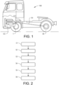
- Fig. 1 shows a vehicle in the form of a heavy-duty truck 100.
- the truck 100 comprises a gearbox 1 according to an example embodiment of the present invention which is drivingly connected to an internal combustion engine ICE.
- the gearbox 1 may for example be the gearbox as shown in fig. 4 .
- an internal combustion engine ICE is shown, the present invention is also applicable to other power units, and combinations thereof, such one or more electric motors drivingly connected to the gearbox 1.
- the gearbox 1 is in this embodiment connected to a propeller shaft 50, which is configured to transfer torque to rear-wheels 40.
- the present invention is applicable to any type of vehicle, such as a bus, a construction equipment vehicle, a passenger car or the like.
- fig. 2 shows a flowchart of a method for defining a clutch slipping point position X sp of a clutch 2 (see fig. 4 ) in a gearbox 1.
- the gearbox 1 comprises an input shaft 3 (see fig. 4 ) and a clutch 2 for the input shaft 3, and the input shaft 3 is arranged to be braked by a braking means 4.
- the braking means 4 may be a brake of the gearbox, as shown in fig. 4 , or any other braking means.
- the method illustrated in the flowchart comprises:
- the clutch transfer characteristics C tc as shown in fig. 3 is a predefined clutch transfer characteristics of a gearbox 1, such as the gearbox 1 shown in fig. 4 .
- a clutch transfer characteristics C tc e.g. in the form of a curve as the one shown in fig. 3 , may be provided for each unique gearbox and/or for a specific type of gearbox. It is well known for the skilled person how to obtain the clutch transfer characteristics, which may be expressed as a curve which defines the clutch torque at a specific clutch position.
- the clutch slipping point position X sp can be found by a slipping point torque T sp in the clutch transfer characteristics C tc .
- the slipping point torque T sp may be defined as a torque value where the torque has started to increase from zero torque, or close to zero torque.
- the slipping point torque T sp may be found in a section of the curve where a change of the derivative of the curve goes from zero to a positive value.
- the slipping point torque T sp may be approximately 30 Nm as mentioned in the above.
- the clutch 2 is preferably moved from the fully disengaged position towards the engaged position with a predefined speed, such as a predefined number of millimetres per second (mm/s).
- the method may further comprise to disengage the clutch 2 to its fully disengaged position after the registered clutch position X b has been reached and apply the braking means 4 again. Thereafter the following may be performed:
- the clutch 2 may be moved to the defined clutch slipping point position X sp at a moving speed which corresponds to a maximum moving speed of the clutch 2, or at least corresponds to 70%, 80% or 90 % of the maximum moving speed of the clutch.
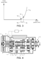
- Fig. 4 shows a schematic view of a gearbox 1 according to an example embodiment of the invention.
- the gearbox 1 is connected to a control unit 10 according to an embodiment of the second aspect of the invention.
- the gearbox 1 as shown is an automated mechanical transmission (AMT) for a truck and comprises a clutch 2, an input shaft 3, a countershaft 6, sets of intermeshing gearwheels 7, 8, 9, 11, and a range gear 12.
- the clutch 2 is adapted to drivingly disengage and engage the input shaft 3 with respect to e.g. the internal combustion engine ICE as shown in fig 1 .
- the gearbox 1 further comprises a braking means 4, which here is connected to the countershaft 6, whereby the input shaft 3 is arranged to be braked by the braking means 4.
- the gearbox 1 further comprises a sensor 5 for measuring a value indicative of a rotational speed of the input shaft 3.
- the sensor 5 may for example be a speed sensor or a sensor which counts a number of cog wheels of a gear wheel which passes the sensor.
- the braking means 4 is connected to and adapted to be controlled by the control unit 10.
- the sensor 5 is also in communicative contact with the control unit 10.
- the control unit 10 is configured to:
- the control unit 10 may be configured to issue the second signal to move the clutch 2 from the fully disengaged position towards the engaged position with a predefined speed.
- the control unit 10 may include a microprocessor, microcontroller, programmable digital signal processor or another programmable device.
- the control unit 10 may also, or instead, include an application specific integrated circuit, a programmable gate array or programmable array logic, a programmable logic device, or a digital signal processor.
- the processor may further include computer executable code that controls operation of the programmable device.
- the control unit 10 may comprise embedded hardware, sometimes with integrated software, where the hardware show close physical relationship. Examples of physical relationships are: shared casing and components mounted on one or several circuit boards. It shall be noted that the control unit 10 may be formed by one or more connected sub control units, or equivalent computer resources.
- the control unit 10 may further be configured to:
- the control unit 10 may further be configured to issue the sixth signal to move the clutch 2 to the defined clutch slipping point position X sp at a moving speed which corresponds to a maximum moving speed of the clutch 2, or at least corresponds to 70%, 80% or 90 % of the maximum moving speed of the clutch 2.
- the control unit 10 may further be configured to:
- the control unit 10 may further be configured to:
- the method as described herein may preferably be performed when the vehicle is in a work shop for e.g. service and/or when the vehicle is standing still, e.g. during a driver break.
Landscapes
- Engineering & Computer Science (AREA)
- General Engineering & Computer Science (AREA)
- Mechanical Engineering (AREA)
- Physics & Mathematics (AREA)
- Fluid Mechanics (AREA)
- Hydraulic Clutches, Magnetic Clutches, Fluid Clutches, And Fluid Joints (AREA)
- Control Of Transmission Device (AREA)
Claims (15)
- Procédé permettant de définir une position de point de glissement d'embrayage (Xsp) d'un embrayage (2) dans une boîte de vitesses (1), dans lequel la boîte de vitesses comprend un arbre d'entrée (3) et dans lequel l'arbre d'entrée est conçu pour être freiné par un moyen de freinage (4), le procédé comprenant :- la détermination (S1) établissant si l'embrayage est traînant lorsque l'embrayage est complètement débrayé ;- lorsqu'il est déterminé que l'embrayage est traînant, l'application (S2) du moyen de freinage avec un couple de frein prédéterminé (Tb) et de sorte que l'arbre d'entrée n'est pas en train de tourner ; et après cela :- le déplacement (S3) de l'embrayage de la position complètement débrayée vers une position embrayée ;- la détermination (S4) du moment où l'arbre d'entrée commence à tourner avec une valeur de rotation prédéterminée indiquant une vitesse de rotation de l'arbre d'entrée ;- l'enregistrement (S5) d'une position d'embrayage (Xb) dans laquelle l'embrayage est positionné lorsque la valeur de rotation prédéterminée est atteinte ;- l'utilisation (S6) d'une caractéristique de transfert d'embrayage de l'embrayage, du couple de frein prédéterminé (Tb) et de la position d'embrayage enregistrée (Xb) pour définir la position de point de glissement d'embrayage (Xsp).
- Procédé selon la revendication 1, dans lequel l'embrayage est déplacé de la position complètement débrayée vers la position embrayée avec une vitesse prédéfinie.
- Procédé selon l'une quelconque des revendications précédentes, comprenant en outre :- le débrayage de l'embrayage vers sa position complètement débrayée après que la position d'embrayage enregistrée a été atteinte ;- l'application du moyen de freinage une nouvelle fois ; et après cela :- le relâchement du moyen de freinage ;- le déplacement de l'embrayage vers la position de point de glissement d'embrayage définie ;- la détermination d'une accélération de l'arbre d'entrée pour vérifier qu'elle correspond à un couple de point de glissement souhaité (Tsp).
- Procédé selon la revendication 3, dans lequel l'embrayage est déplacé vers la position de point de glissement d'embrayage définie à une vitesse de déplacement qui correspond à une vitesse de déplacement maximale de l'embrayage, ou au moins correspond à 70 %, 80 % ou 90 % de la vitesse de déplacement maximale de l'embrayage.
- Procédé selon l'une quelconque des revendications 3 ou 4, comprenant en outre :- la réalisation d'un ajustement de la position de point de glissement d'embrayage vers une plus embrayée si l'accélération déterminée de l'arbre d'entrée est trop basse de telle sorte qu'elle ne correspond pas au couple de point de glissement souhaité.
- Procédé selon l'une quelconque des revendications 3 à 5, comprenant en outre :- la réalisation d'un ajustement de la position de point de glissement d'embrayage vers une plus débrayée si l'accélération déterminée de l'arbre d'entrée est trop élevée de telle sorte qu'elle ne correspond pas au couple de point de glissement souhaité.
- Unité de commande (10) pour une boîte de vitesses comprenant un arbre d'entrée (3) et un embrayage (2) pour l'arbre d'entrée, et dans laquelle l'arbre d'entrée est conçu pour être freiné par un moyen de freinage (4), dans laquelle l'unité de commande est configurée pour :- déterminer si l'embrayage est traînant lorsque l'embrayage est complètement débrayé ;- lorsqu'il est déterminé que l'embrayage est traînant, émettre un premier signal pour appliquer le moyen de freinage avec un couple de frein prédéterminé (Tb) et de sorte que l'arbre d'entrée n'est pas en train de tourner ; et après cela :- émettre un deuxième signal pour déplacer l'embrayage de la position complètement débrayée vers une position embrayée ;- déterminer le moment où l'arbre d'entrée commence à tourner avec une valeur de rotation prédéterminée indiquant une vitesse de rotation de l'arbre d'entrée ;- enregistrer une position d'embrayage (Xb) dans laquelle l'embrayage est positionné lorsque la valeur de rotation prédéterminée est atteinte ;- utiliser une caractéristique de transfert d'embrayage de l'embrayage, le couple de frein prédéterminé (Tb) et la position d'embrayage enregistrée (Xb) pour définir la position de point de glissement d'embrayage (Xsp).
- Unité de commande selon la revendication 7, dans laquelle l'unité de commande est configurée pour émettre le deuxième signal pour déplacer l'embrayage de la position complètement débrayée vers la position embrayée avec une vitesse prédéfinie.
- Unité de commande selon l'une quelconque des revendications 7 ou 8, en outre configurée pour :- émettre un troisième signal pour débrayer l'embrayage vers sa position complètement débrayée après que la position d'embrayage enregistrée a été atteinte ;- émettre un quatrième signal pour appliquer le moyen de freinage une nouvelle fois ; et après cela :- émettre un cinquième signal pour relâcher le moyen de freinage ;- émettre un sixième signal pour déplacer l'embrayage vers la position de point de glissement d'embrayage définie ;- déterminer une accélération de l'arbre d'entrée pour vérifier qu'elle correspond à un couple de point de glissement souhaité.
- Unité de commande selon la revendication 9, en outre configurée pour :- réaliser un ajustement de la position de point de glissement d'embrayage vers une plus embrayée si l'accélération déterminée de l'arbre d'entrée est trop basse de telle sorte qu'elle ne correspond pas au couple de point de glissement souhaité.
- Unité de commande selon l'une quelconque des revendications 9 à 10, en outre configurée pour :- réaliser un ajustement de la position de point de glissement d'embrayage vers une plus débrayée si l'accélération déterminée de l'arbre d'entrée est trop élevée de telle sorte qu'elle ne correspond pas au couple de point de glissement souhaité.
- Boîte de vitesses (1) comprenant un arbre d'entrée et un embrayage (2) pour l'arbre d'entrée, et dans laquelle l'arbre d'entrée est conçu pour être freiné par un moyen de freinage, et comprenant en outre l'unité de commande selon l'une quelconque des revendications 7 à 11.
- Véhicule (100) comprenant l'unité de commande selon l'une quelconque des revendications 7 à 11 et/ou la boîte de vitesses selon la revendication 12.
- Programme informatique comprenant un moyen de code de programme permettant d'effectuer les étapes selon l'une quelconque des revendications 1 à 6, lorsque ledit programme est exécuté sur un ordinateur.
- Support lisible par ordinateur portant un programme informatique comprenant un moyen de code de programme permettant de réaliser les étapes selon l'une quelconque des revendications 1 à 6 lorsque ledit produit de programme est exécuté sur un ordinateur.
Applications Claiming Priority (1)
| Application Number | Priority Date | Filing Date | Title |
|---|---|---|---|
| PCT/EP2019/086033 WO2021121582A1 (fr) | 2019-12-18 | 2019-12-18 | Procédé de définition d'une position de point de glissement d'embrayage |
Publications (3)
| Publication Number | Publication Date |
|---|---|
| EP4077976A1 EP4077976A1 (fr) | 2022-10-26 |
| EP4077976B1 true EP4077976B1 (fr) | 2024-03-20 |
| EP4077976C0 EP4077976C0 (fr) | 2024-03-20 |
Family
ID=69143546
Family Applications (1)
| Application Number | Title | Priority Date | Filing Date |
|---|---|---|---|
| EP19832645.6A Active EP4077976B1 (fr) | 2019-12-18 | 2019-12-18 | Procédé de définition d'une position de point de glissement d'embrayage |
Country Status (5)
| Country | Link |
|---|---|
| US (1) | US11846330B2 (fr) |
| EP (1) | EP4077976B1 (fr) |
| JP (1) | JP7425874B2 (fr) |
| CN (1) | CN114829806A (fr) |
| WO (1) | WO2021121582A1 (fr) |
Families Citing this family (1)
| Publication number | Priority date | Publication date | Assignee | Title |
|---|---|---|---|---|
| WO2021233629A1 (fr) | 2020-05-20 | 2021-11-25 | Magna powertrain gmbh & co kg | Procédé de contrôle de la précision d'actionnement d'un embrayage lorsqu'un véhicule à moteur électrique ou hybride est à l'arrêt |
Family Cites Families (13)
| Publication number | Priority date | Publication date | Assignee | Title |
|---|---|---|---|---|
| US4899858A (en) * | 1989-03-02 | 1990-02-13 | Eaton Corporation | Method and control system for updating of control parameter value indicative of master clutch point of incipient engagement |
| CA2085517C (fr) * | 1992-01-02 | 1999-04-13 | Chia-Hsiang Liu | Determination du point de contact pour commande automatique d'embrayage |
| US5337868A (en) * | 1992-01-02 | 1994-08-16 | Eaton Corporation | Touch point identification for automatic clutch controller |
| US5393274A (en) * | 1993-07-19 | 1995-02-28 | Eaton Corporation | Touch point identification algorithm for automatic clutch controller |
| JP3484487B2 (ja) * | 1995-02-10 | 2004-01-06 | イートン コーポレーション | クラッチ接触点決定方法及びその装置 |
| US6022295A (en) * | 1998-11-12 | 2000-02-08 | Eaton Corporation | Touch point identification for vehicle master clutch |
| SE525163C2 (sv) * | 2004-01-14 | 2004-12-14 | Volvo Lastvagnar Ab | Drivaggregat för motorfordon samt metod för att fastställa karaktistiken hos drivaggregatets koppling |
| DE102006019824A1 (de) * | 2006-04-28 | 2007-10-31 | Zf Friedrichshafen Ag | Verfahren zur Ermittlung einer Drehmomentkennlinie einer automatisierten Reibungskupplung |
| SE534245C2 (sv) * | 2009-09-14 | 2011-06-14 | Scania Cv Ab | Metod och system för bestämning av kontaktpunkten för en koppling vid ett fordon |
| JP5501083B2 (ja) | 2010-04-28 | 2014-05-21 | アイシン・エーアイ株式会社 | 車両の動力伝達制御装置 |
| KR101355620B1 (ko) * | 2012-11-09 | 2014-01-27 | 기아자동차주식회사 | 클러치의 터치포인트 탐색 방법 |
| CN109990015B (zh) * | 2017-12-29 | 2020-08-18 | 长城汽车股份有限公司 | 双离合器半结合点的自学习方法 |
| DE102018125509A1 (de) * | 2018-10-15 | 2019-01-17 | FEV Europe GmbH | Kontaktpunktbestimmung bei Trockenkupplungen |
-
2019
- 2019-12-18 US US17/785,577 patent/US11846330B2/en active Active
- 2019-12-18 WO PCT/EP2019/086033 patent/WO2021121582A1/fr not_active Ceased
- 2019-12-18 EP EP19832645.6A patent/EP4077976B1/fr active Active
- 2019-12-18 JP JP2022536714A patent/JP7425874B2/ja active Active
- 2019-12-18 CN CN201980103006.2A patent/CN114829806A/zh active Pending
Also Published As
| Publication number | Publication date |
|---|---|
| WO2021121582A1 (fr) | 2021-06-24 |
| JP2023514923A (ja) | 2023-04-12 |
| EP4077976C0 (fr) | 2024-03-20 |
| US20230023400A1 (en) | 2023-01-26 |
| CN114829806A (zh) | 2022-07-29 |
| US11846330B2 (en) | 2023-12-19 |
| JP7425874B2 (ja) | 2024-01-31 |
| EP4077976A1 (fr) | 2022-10-26 |
Similar Documents
| Publication | Publication Date | Title |
|---|---|---|
| CN106926749B (zh) | 一种电动汽车蠕行扭矩的控制方法 | |
| CN102859224B (zh) | 用于适配汽车动力传动系中离合器的接触点的方法 | |
| CN108657162B (zh) | 一种换挡控制方法及系统 | |
| US8849529B2 (en) | Method and system for determining the contact point for a clutch in a vehicle | |
| CN106004520A (zh) | 一种车速控制方法、控制系统及电动汽车 | |
| EP4077976B1 (fr) | Procédé de définition d'une position de point de glissement d'embrayage | |
| CN102853067A (zh) | Amt变速器输入轴转速传感器失效的控制方法及装置 | |
| JP2014508263A (ja) | 接触点適応の必要性を決定する方法およびシステム | |
| EP3350485B1 (fr) | Groupe motopropulseur de véhicule et procédé de passage à un rapport supérieur d'engrenage | |
| US10245949B2 (en) | Method for operating a motor vehicle including an all-wheel drive that can be enabled and disabled by determining an angular acceleration of components, which are uncoupled when the all-wheel drive is disabled | |
| KR101775174B1 (ko) | 자동차의 크리핑 과정 제어 방법 | |
| CN104981368A (zh) | 机动车辆动力机构的联结/断联控制方法 | |
| US11840237B2 (en) | Control device and method for controlling a vehicle powertrain to overcome, or avoid, a cog-to-cog condition, computer program, computer-readable medium and vehicle | |
| CN108177647A (zh) | 一种车辆及其控制方法和装置 | |
| SE538412C2 (en) | Device and method for giving feedback about a drivers use of a clutch | |
| KR101558754B1 (ko) | 하이브리드 차량용 주행 제어방법 및 장치 | |
| EP4663967A1 (fr) | Procédé d'estimation d'une position de point de glissement d'embrayage | |
| US10125827B2 (en) | Method of controlling clutch for vehicles | |
| KR102156704B1 (ko) | 하이브리드 dct 차량의 변속 제어방법 | |
| US20230122960A1 (en) | Automated mechanical transmission for a vehicle | |
| CN111315608A (zh) | 用于确定具有至少一个离合器的自动变速器的离合器参数的方法 | |
| WO2018233757A1 (fr) | Procédé pour déterminer correctement l'énergie de frottement générée dans un embrayage pendant le démarrage d'un véhicule avec une boîte de vitesses manuelle | |
| SE1650139A1 (en) | Method for Assessing Engine Characteristic and Computer Program and Computer Program Product and Vehicle | |
| KR20080022773A (ko) | 2륜 구동 차량의 차량안전 시스템 제어방법 | |
| CN118323153A (zh) | 一种输出轴转速方向的确定方法、装置及设备 |
Legal Events
| Date | Code | Title | Description |
|---|---|---|---|
| STAA | Information on the status of an ep patent application or granted ep patent |
Free format text: STATUS: UNKNOWN |
|
| STAA | Information on the status of an ep patent application or granted ep patent |
Free format text: STATUS: THE INTERNATIONAL PUBLICATION HAS BEEN MADE |
|
| PUAI | Public reference made under article 153(3) epc to a published international application that has entered the european phase |
Free format text: ORIGINAL CODE: 0009012 |
|
| STAA | Information on the status of an ep patent application or granted ep patent |
Free format text: STATUS: REQUEST FOR EXAMINATION WAS MADE |
|
| 17P | Request for examination filed |
Effective date: 20220705 |
|
| AK | Designated contracting states |
Kind code of ref document: A1 Designated state(s): AL AT BE BG CH CY CZ DE DK EE ES FI FR GB GR HR HU IE IS IT LI LT LU LV MC MK MT NL NO PL PT RO RS SE SI SK SM TR |
|
| DAV | Request for validation of the european patent (deleted) | ||
| DAX | Request for extension of the european patent (deleted) | ||
| GRAP | Despatch of communication of intention to grant a patent |
Free format text: ORIGINAL CODE: EPIDOSNIGR1 |
|
| STAA | Information on the status of an ep patent application or granted ep patent |
Free format text: STATUS: GRANT OF PATENT IS INTENDED |
|
| INTG | Intention to grant announced |
Effective date: 20230725 |
|
| GRAJ | Information related to disapproval of communication of intention to grant by the applicant or resumption of examination proceedings by the epo deleted |
Free format text: ORIGINAL CODE: EPIDOSDIGR1 |
|
| STAA | Information on the status of an ep patent application or granted ep patent |
Free format text: STATUS: REQUEST FOR EXAMINATION WAS MADE |
|
| GRAP | Despatch of communication of intention to grant a patent |
Free format text: ORIGINAL CODE: EPIDOSNIGR1 |
|
| STAA | Information on the status of an ep patent application or granted ep patent |
Free format text: STATUS: GRANT OF PATENT IS INTENDED |
|
| INTC | Intention to grant announced (deleted) | ||
| INTG | Intention to grant announced |
Effective date: 20231108 |
|
| GRAS | Grant fee paid |
Free format text: ORIGINAL CODE: EPIDOSNIGR3 |
|
| GRAA | (expected) grant |
Free format text: ORIGINAL CODE: 0009210 |
|
| STAA | Information on the status of an ep patent application or granted ep patent |
Free format text: STATUS: THE PATENT HAS BEEN GRANTED |
|
| AK | Designated contracting states |
Kind code of ref document: B1 Designated state(s): AL AT BE BG CH CY CZ DE DK EE ES FI FR GB GR HR HU IE IS IT LI LT LU LV MC MK MT NL NO PL PT RO RS SE SI SK SM TR |
|
| REG | Reference to a national code |
Ref country code: GB Ref legal event code: FG4D |
|
| REG | Reference to a national code |
Ref country code: CH Ref legal event code: EP |
|
| REG | Reference to a national code |
Ref country code: IE Ref legal event code: FG4D |
|
| REG | Reference to a national code |
Ref country code: DE Ref legal event code: R096 Ref document number: 602019048735 Country of ref document: DE |
|
| U01 | Request for unitary effect filed |
Effective date: 20240419 |
|
| U07 | Unitary effect registered |
Designated state(s): AT BE BG DE DK EE FI FR IT LT LU LV MT NL PT SE SI Effective date: 20240424 |
|
| PG25 | Lapsed in a contracting state [announced via postgrant information from national office to epo] |
Ref country code: GR Free format text: LAPSE BECAUSE OF FAILURE TO SUBMIT A TRANSLATION OF THE DESCRIPTION OR TO PAY THE FEE WITHIN THE PRESCRIBED TIME-LIMIT Effective date: 20240621 |
|
| PG25 | Lapsed in a contracting state [announced via postgrant information from national office to epo] |
Ref country code: RS Free format text: LAPSE BECAUSE OF FAILURE TO SUBMIT A TRANSLATION OF THE DESCRIPTION OR TO PAY THE FEE WITHIN THE PRESCRIBED TIME-LIMIT Effective date: 20240620 Ref country code: HR Free format text: LAPSE BECAUSE OF FAILURE TO SUBMIT A TRANSLATION OF THE DESCRIPTION OR TO PAY THE FEE WITHIN THE PRESCRIBED TIME-LIMIT Effective date: 20240320 |
|
| PG25 | Lapsed in a contracting state [announced via postgrant information from national office to epo] |
Ref country code: RS Free format text: LAPSE BECAUSE OF FAILURE TO SUBMIT A TRANSLATION OF THE DESCRIPTION OR TO PAY THE FEE WITHIN THE PRESCRIBED TIME-LIMIT Effective date: 20240620 Ref country code: NO Free format text: LAPSE BECAUSE OF FAILURE TO SUBMIT A TRANSLATION OF THE DESCRIPTION OR TO PAY THE FEE WITHIN THE PRESCRIBED TIME-LIMIT Effective date: 20240620 Ref country code: HR Free format text: LAPSE BECAUSE OF FAILURE TO SUBMIT A TRANSLATION OF THE DESCRIPTION OR TO PAY THE FEE WITHIN THE PRESCRIBED TIME-LIMIT Effective date: 20240320 Ref country code: GR Free format text: LAPSE BECAUSE OF FAILURE TO SUBMIT A TRANSLATION OF THE DESCRIPTION OR TO PAY THE FEE WITHIN THE PRESCRIBED TIME-LIMIT Effective date: 20240621 |
|
| PG25 | Lapsed in a contracting state [announced via postgrant information from national office to epo] |
Ref country code: IS Free format text: LAPSE BECAUSE OF FAILURE TO SUBMIT A TRANSLATION OF THE DESCRIPTION OR TO PAY THE FEE WITHIN THE PRESCRIBED TIME-LIMIT Effective date: 20240720 |
|
| PG25 | Lapsed in a contracting state [announced via postgrant information from national office to epo] |
Ref country code: SM Free format text: LAPSE BECAUSE OF FAILURE TO SUBMIT A TRANSLATION OF THE DESCRIPTION OR TO PAY THE FEE WITHIN THE PRESCRIBED TIME-LIMIT Effective date: 20240320 |
|
| PG25 | Lapsed in a contracting state [announced via postgrant information from national office to epo] |
Ref country code: ES Free format text: LAPSE BECAUSE OF FAILURE TO SUBMIT A TRANSLATION OF THE DESCRIPTION OR TO PAY THE FEE WITHIN THE PRESCRIBED TIME-LIMIT Effective date: 20240320 |
|
| PG25 | Lapsed in a contracting state [announced via postgrant information from national office to epo] |
Ref country code: CZ Free format text: LAPSE BECAUSE OF FAILURE TO SUBMIT A TRANSLATION OF THE DESCRIPTION OR TO PAY THE FEE WITHIN THE PRESCRIBED TIME-LIMIT Effective date: 20240320 |
|
| PG25 | Lapsed in a contracting state [announced via postgrant information from national office to epo] |
Ref country code: PL Free format text: LAPSE BECAUSE OF FAILURE TO SUBMIT A TRANSLATION OF THE DESCRIPTION OR TO PAY THE FEE WITHIN THE PRESCRIBED TIME-LIMIT Effective date: 20240320 |
|
| PG25 | Lapsed in a contracting state [announced via postgrant information from national office to epo] |
Ref country code: SK Free format text: LAPSE BECAUSE OF FAILURE TO SUBMIT A TRANSLATION OF THE DESCRIPTION OR TO PAY THE FEE WITHIN THE PRESCRIBED TIME-LIMIT Effective date: 20240320 |
|
| PG25 | Lapsed in a contracting state [announced via postgrant information from national office to epo] |
Ref country code: SM Free format text: LAPSE BECAUSE OF FAILURE TO SUBMIT A TRANSLATION OF THE DESCRIPTION OR TO PAY THE FEE WITHIN THE PRESCRIBED TIME-LIMIT Effective date: 20240320 Ref country code: SK Free format text: LAPSE BECAUSE OF FAILURE TO SUBMIT A TRANSLATION OF THE DESCRIPTION OR TO PAY THE FEE WITHIN THE PRESCRIBED TIME-LIMIT Effective date: 20240320 Ref country code: RO Free format text: LAPSE BECAUSE OF FAILURE TO SUBMIT A TRANSLATION OF THE DESCRIPTION OR TO PAY THE FEE WITHIN THE PRESCRIBED TIME-LIMIT Effective date: 20240320 Ref country code: PL Free format text: LAPSE BECAUSE OF FAILURE TO SUBMIT A TRANSLATION OF THE DESCRIPTION OR TO PAY THE FEE WITHIN THE PRESCRIBED TIME-LIMIT Effective date: 20240320 Ref country code: IS Free format text: LAPSE BECAUSE OF FAILURE TO SUBMIT A TRANSLATION OF THE DESCRIPTION OR TO PAY THE FEE WITHIN THE PRESCRIBED TIME-LIMIT Effective date: 20240720 Ref country code: ES Free format text: LAPSE BECAUSE OF FAILURE TO SUBMIT A TRANSLATION OF THE DESCRIPTION OR TO PAY THE FEE WITHIN THE PRESCRIBED TIME-LIMIT Effective date: 20240320 Ref country code: CZ Free format text: LAPSE BECAUSE OF FAILURE TO SUBMIT A TRANSLATION OF THE DESCRIPTION OR TO PAY THE FEE WITHIN THE PRESCRIBED TIME-LIMIT Effective date: 20240320 |
|
| REG | Reference to a national code |
Ref country code: DE Ref legal event code: R097 Ref document number: 602019048735 Country of ref document: DE |
|
| PLBE | No opposition filed within time limit |
Free format text: ORIGINAL CODE: 0009261 |
|
| STAA | Information on the status of an ep patent application or granted ep patent |
Free format text: STATUS: NO OPPOSITION FILED WITHIN TIME LIMIT |
|
| U20 | Renewal fee for the european patent with unitary effect paid |
Year of fee payment: 6 Effective date: 20241225 |
|
| U1N | Appointed representative for the unitary patent procedure changed after the registration of the unitary effect |
Representative=s name: KRANSELL & WENNBORG KB; SE |
|
| 26N | No opposition filed |
Effective date: 20241223 |
|
| PG25 | Lapsed in a contracting state [announced via postgrant information from national office to epo] |
Ref country code: MC Free format text: LAPSE BECAUSE OF FAILURE TO SUBMIT A TRANSLATION OF THE DESCRIPTION OR TO PAY THE FEE WITHIN THE PRESCRIBED TIME-LIMIT Effective date: 20240320 |
|
| REG | Reference to a national code |
Ref country code: CH Ref legal event code: PL |
|
| GBPC | Gb: european patent ceased through non-payment of renewal fee |
Effective date: 20241218 |
|
| PG25 | Lapsed in a contracting state [announced via postgrant information from national office to epo] |
Ref country code: GB Free format text: LAPSE BECAUSE OF NON-PAYMENT OF DUE FEES Effective date: 20241218 |
|
| PG25 | Lapsed in a contracting state [announced via postgrant information from national office to epo] |
Ref country code: CH Free format text: LAPSE BECAUSE OF NON-PAYMENT OF DUE FEES Effective date: 20241231 |
|
| PG25 | Lapsed in a contracting state [announced via postgrant information from national office to epo] |
Ref country code: IE Free format text: LAPSE BECAUSE OF NON-PAYMENT OF DUE FEES Effective date: 20241218 |
|
| U20 | Renewal fee for the european patent with unitary effect paid |
Year of fee payment: 7 Effective date: 20251223 |