EP4078032B1 - Composant de brûleur d'un brûleur et brûleur d'une turbine à gaz doté d'un tel composant - Google Patents
Composant de brûleur d'un brûleur et brûleur d'une turbine à gaz doté d'un tel composant Download PDFInfo
- Publication number
- EP4078032B1 EP4078032B1 EP20828979.3A EP20828979A EP4078032B1 EP 4078032 B1 EP4078032 B1 EP 4078032B1 EP 20828979 A EP20828979 A EP 20828979A EP 4078032 B1 EP4078032 B1 EP 4078032B1
- Authority
- EP
- European Patent Office
- Prior art keywords
- burner
- vortex generator
- burner component
- vortex
- component
- Prior art date
- Legal status (The legal status is an assumption and is not a legal conclusion. Google has not performed a legal analysis and makes no representation as to the accuracy of the status listed.)
- Active
Links
Images


Classifications
-
- F—MECHANICAL ENGINEERING; LIGHTING; HEATING; WEAPONS; BLASTING
- F23—COMBUSTION APPARATUS; COMBUSTION PROCESSES
- F23D—BURNERS
- F23D11/00—Burners using a direct spraying action of liquid droplets or vaporised liquid into the combustion space
- F23D11/24—Burners using a direct spraying action of liquid droplets or vaporised liquid into the combustion space by pressurisation of the fuel before a nozzle through which it is sprayed by a substantial pressure reduction into a space
-
- F—MECHANICAL ENGINEERING; LIGHTING; HEATING; WEAPONS; BLASTING
- F23—COMBUSTION APPARATUS; COMBUSTION PROCESSES
- F23D—BURNERS
- F23D11/00—Burners using a direct spraying action of liquid droplets or vaporised liquid into the combustion space
- F23D11/36—Details
-
- F—MECHANICAL ENGINEERING; LIGHTING; HEATING; WEAPONS; BLASTING
- F23—COMBUSTION APPARATUS; COMBUSTION PROCESSES
- F23D—BURNERS
- F23D14/00—Burners for combustion of a gas, e.g. of a gas stored under pressure as a liquid
- F23D14/20—Non-premix gas burners, i.e. in which gaseous fuel is mixed with combustion air on arrival at the combustion zone
-
- F—MECHANICAL ENGINEERING; LIGHTING; HEATING; WEAPONS; BLASTING
- F23—COMBUSTION APPARATUS; COMBUSTION PROCESSES
- F23D—BURNERS
- F23D14/00—Burners for combustion of a gas, e.g. of a gas stored under pressure as a liquid
- F23D14/46—Details
- F23D14/70—Baffles or like flow-disturbing devices
-
- F—MECHANICAL ENGINEERING; LIGHTING; HEATING; WEAPONS; BLASTING
- F23—COMBUSTION APPARATUS; COMBUSTION PROCESSES
- F23R—GENERATING COMBUSTION PRODUCTS OF HIGH PRESSURE OR HIGH VELOCITY, e.g. GAS-TURBINE COMBUSTION CHAMBERS
- F23R3/00—Continuous combustion chambers using liquid or gaseous fuel
- F23R3/02—Continuous combustion chambers using liquid or gaseous fuel characterised by the air-flow or gas-flow configuration
- F23R3/04—Air inlet arrangements
- F23R3/10—Air inlet arrangements for primary air
- F23R3/12—Air inlet arrangements for primary air inducing a vortex
-
- F—MECHANICAL ENGINEERING; LIGHTING; HEATING; WEAPONS; BLASTING
- F23—COMBUSTION APPARATUS; COMBUSTION PROCESSES
- F23R—GENERATING COMBUSTION PRODUCTS OF HIGH PRESSURE OR HIGH VELOCITY, e.g. GAS-TURBINE COMBUSTION CHAMBERS
- F23R3/00—Continuous combustion chambers using liquid or gaseous fuel
- F23R3/28—Continuous combustion chambers using liquid or gaseous fuel characterised by the fuel supply
- F23R3/286—Continuous combustion chambers using liquid or gaseous fuel characterised by the fuel supply having fuel-air premixing devices
-
- F—MECHANICAL ENGINEERING; LIGHTING; HEATING; WEAPONS; BLASTING
- F23—COMBUSTION APPARATUS; COMBUSTION PROCESSES
- F23D—BURNERS
- F23D2900/00—Special features of, or arrangements for burners using fluid fuels or solid fuels suspended in a carrier gas
- F23D2900/14—Special features of gas burners
- F23D2900/14003—Special features of gas burners with more than one nozzle
Definitions
- the invention relates to a burner component of a burner for use in a gas turbine.
- the task of the burner component considered here is to cause or promote a swirling of combustion air with fuel.
- disruptive elements are usually arranged in the flow path, which divert the flow and cause swirling.
- Blade-like structures are often used for this purpose.
- vortex generators are arranged in the flow channel for the combustion air, which have a triangular isosceles shape in the direction of the flow, rising downstream from the wall of the flow channel. This also results in a triangular shape in the form of a right-angled triangle when viewed from the side transverse to the direction of flow. Furthermore, when viewed perpendicular to the wall of the flow channel, transverse to the direction of flow, the shape is triangular.
- the aim is to keep the flow resistance as low as possible and still ensure sufficient mixing.
- the object of the present invention is therefore to achieve improved mixing with the lowest possible resistance.
- the generic burner component is intended to be a component of a burner.
- the type of burner is initially irrelevant, but the burner component is advantageously used in a burner of a gas turbine. It is obvious that the burner is to be arranged on the upstream side of a combustion chamber.
- the burner has a flow channel in which combustion air flows in a flow direction from upstream to downstream.
- the flow channel is necessarily delimited by a wall.
- the burner component now comprises, at least in sections, the wall adjacent to the flow channel as a wall section.
- injection nozzles are arranged on the wall section. How the fuel is supplied to the injection nozzles is initially irrelevant. At the very least, the injection nozzles are provided to enable the introduction of fuel into the flow channel. Consequently, the injection nozzles are initially connected to a fuel channel regardless of how it is designed or arranged.
- vortex generators there are several vortex generators on the wall section in close proximity to the injection nozzles.
- the vortex generators are each arranged on the wall section and protrude into the flow channel. Accordingly, the vortex generators act as an obstacle in the flow channel and cause the combustion air to swirl.
- the vortex generators have a shape with a starting edge running along the wall section.
- the starting edge represents the boundary of the vortex generator on the upstream side.
- the starting edge can have either an arcuate or a straight line.
- the starting edge runs along (not necessarily exactly in) a transverse direction, which is aligned transversely to the flow direction and on the wall section or tangentially to the wall section.
- each vortex generator There is a terminal edge on the downstream side of each vortex generator.
- the terminal edge extends along (not necessarily exactly in) a vertical direction.
- the vertical direction is aligned transversely to the wall section and transversely to the flow direction.
- the end of the terminal edge on the wall section forms a base point, with an end point located opposite on the terminal edge.
- the vortex generator has a vortex generator height, which is measured in the vertical direction and extends from the base point to the end point.
- the respective vortex generator is limited by two oppositely arranged side surfaces.
- the side surfaces run from the end edge upstream to the opposite edge ends of the starting edge.
- the vortex generator is also limited by a gradient surface that begins at the starting edge and runs to the end point. Consequently, the gradient surface is laterally limited at least in sections by the side surfaces.
- the vortex generators in the design considered here have an approximately triangular shape when viewed from different sides. This applies both when viewed in the direction of flow and in the vertical direction with a view of the gradient surface. Likewise, when viewed in the transverse direction, the respective side surface has an approximately triangular shape.
- the vortex generator has approximately the shape of a tetrahedron, with one face of the tetrahedron being formed by the wall surface and one edge of the tetrahedron being the starting edge and one edge being the ending edge.
- the vortex generator has a vortex generator length which is measured in the direction of flow and extends from the starting edge to the base point. If the starting edge does not extend in a straight line in the transverse direction, the point on the starting edge which is located furthest upstream should be selected. This point can be the middle, but in the case of a non-flat wall section it will usually be an edge end of the starting edge. While in the prior art a planar gradient surface is provided for the specific shape of the vortex generator, according to the invention the gradient surface is now designed to be concavely curved. This means that the gradient surface is a curved surface that is recessed into the vortex generator.
- the optimization of the turbulence is achieved according to the invention when the gradient surface forms a section of a spherical surface.
- a curvature that has a certain deviation from a planar gradient plane has proven to be advantageous in terms of improving the mixing by converting a planar plane into a concave gradient plane.
- the gradient plane is defined by the end point and two other points on the peripheral edge of the gradient plane, so that the gradient plane lies completely below the gradient plane.
- a surface depth can also be determined, with the surface depth being the greatest distance from the concave gradient plane to the planar gradient plane.
- a surface depth of at least 0.05 times the vortex generator height and a maximum of 0.4 times the vortex generator height is preferred.
- a surface depth of at least 0.1 times the vortex generator height is particularly advantageous. It is also particularly advantageous if the surface depth corresponds to a maximum of 0.3 times the vortex generator height.
- the side surfaces In contrast to the usual planar design of the side surfaces, it has proven to be advantageous to design the side surfaces so that they are curved outwards.
- the side surfaces show a convex curvature when cut through the vortex generator along a plane transverse to the vertical direction.
- the respective side surfaces form a section of a cylindrical surface in the simplest form.
- a vortex generator Independently of the concavely shaped gradient surface according to the invention, a vortex generator has special features, in particular size ratios, so that an advantageous effect is achieved.
- the width in the transverse direction corresponds to at least 0.5 times the length of the vortex generator.
- a width of the vortex generator of at least 0.8 times the length of the vortex generator is particularly advantageous.
- the vortex generator length is at least 0.5 times the width of the vortex generator.
- a vortex generator length of at least 0.8 times the width of the vortex generator is particularly advantageous.
- the beneficial effect of the vortex generator is further ensured if the vortex generator length is at least 0.8 times the vortex generator height.
- a vortex generator length of at least the vortex generator height is particularly advantageous.
- the height of the vortex generator should not be more than 1.5 times the length of the vortex generator. It is particularly advantageous if the height of the vortex generator is smaller than the length of the vortex generator.
- the injection nozzle is formed by a round bore with a nozzle diameter.
- the nozzle diameter of the injection nozzle is at least 0.1 times the vortex generator height.
- a nozzle diameter of at least 0.2 times the vortex generator height is particularly advantageous here.
- the nozzle diameter should not be too large in relation to the vortex generator, as otherwise the beneficial effect of the vortex generator will be lost. Therefore, the nozzle diameter should be smaller than 0.6 times the height of the vortex generator. A nozzle diameter of a maximum of 0.4 times the height of the vortex generator is particularly advantageous.
- an equivalent nozzle diameter shall be determined from the cross-sectional area of the injector.
- an injection nozzle can advantageously be arranged on at least one side of the vortex generator in a side surface of the vortex generator or in the immediately adjacent wall section at a distance from the base point of a maximum of 0.3 times the height of the vortex generator. It is particularly preferred if the distance of the injection nozzles (regardless of the arrangement in the side surface or the wall section) from the base point corresponds to a maximum of 0.2 times the height of the vortex generator. Furthermore, an injection nozzle can advantageously be arranged on both sides of the vortex generator.
- the injection nozzles are arranged centrally to the respective vortex generator. In combination with the alignment of the vortex generator with a gradient surface that rises downstream, an advantageous mixing of the fuel in the combustion air downstream of the vortex generator is achieved.
- the injection nozzles are arranged centrally, it can be advantageous to arrange the injection nozzles directly on the vortex generator at the end edge (the injection nozzles thus interrupt the end edge or reduce its length at the base point).
- the injection nozzle can be arranged downstream of the vortex generator in the wall section.
- the distance between the injection nozzle and the base point is no more than 0.5 times the height of the vortex generator. It is particularly advantageous if the distance is no more than 0.3 times the height of the vortex generator. This means that the advantageous influence of the vortex generator with the concave gradient surface is optimally exploited to achieve the best possible mixing of the fuel in the combustion air.
- the injection nozzle when arranged on the wall section, is arranged at a distance from the base point of at least 0.1 times the height of the vortex generator.
- the distance to the edge of the injection nozzle is considered for the previously specified advantageous distances.
- the base point is determined as an extension of the end edge without rounding.
- a further advantageous introduction of the fuel into the combustion air is made possible by arranging at least one injection nozzle between each two vortex generators. It is particularly advantageous to arrange exactly one injection nozzle centrally between the vortex generators.
- the arrangement in this regard refers to the position in the transverse direction.
- the at least one injection nozzle between the vortex generators is also positioned in spatial proximity to the base point when viewed in the direction of flow. It is advantageous if the distance from the base point to the injection nozzle also corresponds to a maximum of 0.5 times the height of the vortex generator. It has been shown to be particularly preferred if the arrangement of the injection nozzle takes place downstream of the base point at a maximum distance of 0.3 times the height of the vortex generator.
- the plurality of vortex generators can be arranged next to one another and offset from one another in the direction of flow.
- the vortex generators are preferably arranged next to one another at the same height in the direction of flow. In this regard, it is irrelevant whether other means for swirling the air flow are arranged upstream or downstream outside the immediate area of influence of the vortex generators.
- the vortex generators are arranged at a distance from one another in the transverse direction.
- the vortex generators are directly adjacent to one another. It is particularly advantageous here if the adjacent arrangement of the vortex generators means that the adjacent slope surfaces each have a common edge section.
- the burner component as part of a burner can fulfill different functions.
- the burner component can form a pipe section that surrounds the flow channel.
- the burner component can also form a section of a wall of the flow channel, with two or more sections, each as a burner component, for example, surrounding the flow channel.
- the wall can also be a surface of a swirl vane that is arranged in a flow channel.
- the burner component is intended to border on the flow channel in accordance with the intended task of causing a mixing of fuel in combustion air.
- the burner component forms a burner lance.
- the burner lance has a rotation-shaped wall, whereby the flow channel surrounds the wall section of the burner component.
- the vortex generators are distributed around the circumference of the wall section, with the vortex generators being designed as previously described.
- a burner component according to the invention leads to the formation of a burner according to the invention, which is used as intended in a combustion chamber.
- the use of the burner in a combustion chamber of a gas turbine is particularly advantageous, wherein the burner component is preferably a burner lance.
- the burner comprises at least one mixing tube which surrounds the flow channel and is arranged upstream of the combustion chamber.
- the burner component used here with a design as described above is arranged centrally in the mixing tube.
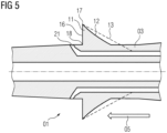
- FIG. 1 is shown in a perspective view of an exemplary embodiment for a burner component 01 according to the invention in the form of a burner lance.
- the typical rotational, elongated shape of the burner lance 01 can be seen.
- the slightly conical wall of the burner lance forms the wall section 03 of the burner component 01 as a limiting surface for the flow channel provided in the burner as intended. This accordingly defines the flow direction 05 from an upstream side to a downstream side.
- vortex generators 11 distributed around the circumference, each of which has an approximately triangular shape when viewed from different directions.
- the vortex generator 11 has approximately the shape of a tetrahedron.
- injection nozzles 21,22 which are arranged downstream of the vortex generators 11.
- the respective vortex generator 11 is limited upstream by a starting edge 14.
- the starting edge 14 runs along a transverse direction which is aligned perpendicular to the flow direction and tangential to the wall section 03. Due to the arrangement of the vortex generators 11 on the rotational wall section 03, the starting edge 14 is curved so that the two opposite edge ends 15 of the starting edge 14 are arranged furthest upstream.
- the vortex generator 11 is limited by the end edge 16, which extends approximately in a respective vertical direction from a base point 18 on the wall section 03 to an end point 17. The vertical direction is aligned approximately perpendicular to the flow direction and perpendicular to the wall section 03 at the base point 18.
- the distance from the base point 18 to the end point 17 measured in the vertical direction defines the vortex generator height.
- the distance from the end edge 16 to the edge ends 15 measured in the flow direction 05 defines a vortex generator length.
- the respective vortex generator 11 is laterally delimited by two opposite side surfaces 19, which each extend from the end edge in the direction of the respective edge end 15 of the starting edge 14.
- the side surfaces 19 have a curved, convex shape.
- the surface of the vortex generator that is essential for swirling the fuel in the combustion air is the slope surface 12, which extends from the starting edge 14 to the end point 17. Accordingly, the slope surface 12 is partially delimited by cutting edges with the two side surfaces 19.
- the vortex generators 11 are arranged adjacent to one another in such a way that a common edge section of the adjacent slope surfaces 12 is formed in sections, starting from the respective edge end 15 up to essentially the beginning of the side surfaces 19.
- the gradient surface 12 has a convexly curved shape. This is the decisive feature for achieving the advantageous turbulence and thus a further possibility for reducing pollutants during combustion.
- the gradient surface 12 is located below a theoretical gradient plane 13.
- the gradient plane 13 is defined by the end point 17 and the two edge ends 15, so that the gradient surface 12 is arranged completely below the gradient plane 13.
- the greatest distance between the gradient surface 12 and the theoretical gradient plane 13 as a surface depth corresponds to 0.2 times the vortex generator height.
- injection nozzles 21, 22 can also be seen from the views.
- an injection nozzle 21 is located in the wall section 03 in the middle behind each vortex generator 11.
- the distance from the edge of the respective injection nozzle 21 to the base point 18 of the end edge 16 is approximately 0.25 times the height of the vortex generator in this exemplary embodiment.
- a further injection nozzle 22 is arranged on the wall section 03 between each two vortex generators 11.
- the distance from the edge of the injection nozzle 22 to the base point 18 of the vortex generator 11 is approximately 0.15 times the height of the vortex generator.
Landscapes
- Engineering & Computer Science (AREA)
- Chemical & Material Sciences (AREA)
- Combustion & Propulsion (AREA)
- Mechanical Engineering (AREA)
- General Engineering & Computer Science (AREA)
- Pressure-Spray And Ultrasonic-Wave- Spray Burners (AREA)
- Gas Burners (AREA)
Claims (14)
- Composant (01) de brûleur d'un brûleur, à utiliser, en particulier pour une chambre de combustion d'une turbine à gaz, comprenant au moins un conduit d'écoulement conforme aux prescriptions, dans lequel de l'air de combustion s'écoule dans un sens (05) d'écoulement de l'amont vers l'aval, comprenant un tronçon (03) de paroi voisin du conduit d'écoulement et plusieurs buses (21, 22) d'injection, qui sont montées dans le tronçon (03) de paroi et au moyen desquelles du combustible peut être introduit dans le conduit d'écoulement, et plusieurs tourbillonneurs (11), lesquels (11) respectivement- sont montés sur le tronçon (03) de paroi et- pénètrent dans le conduit d'écoulement et- ont une longueur de tourbillonneur dans le sens (5) d'écoulement et- en amont un bord (14) de début s'étendant sur le tronçon (03) de paroi et- en aval un bord (16) de fin s'étendant le long d'une direction respective en hauteur et ayant un point (18) de pied sur le tronçon de paroi et un point (17) de fin, dans lequel le tourbillonneur (11) a une hauteur de tourbillonneur, qui est définie, mesurée dans la direction en hauteur, par la distance du point (18) de pied au point (17) de fin,- deux surfaces (19) latérales opposées s'étendant en amont du bord (16) de fin et- une surface (12) en pente s'étendant du bord (14) de début au point (17) de fin,caractériséen ce que la surface (12) en pente est incurvée de manière concave et les surfaces (19) latérales de manière convexe dans une coupe transversalement à la direction en hauteur,dans lequel la surface (12) en pente forme un tronçon d'une surface sphérique.
- Composant (01) de brûleur suivant la revendication 1,dans lequel une profondeur de surface, comme distance la plus grande de la surface (12) en pente à un premier plan (13) en pente, représente au moins 0,05 fois la hauteur du tourbillonneur ; et/oudans lequel une profondeur de surface, comme distance la plus grande de la surface (12) en pente à un plan (13) en pente, représente au maximum 0,4 fois la hauteur du tourbillonneur.
- Composant (01) de brûleur suivant la revendication 2,dans lequel une profondeur de surface, comme distance la plus grande de la surface (12) en pente à un plan (13) en pente, représente au moins 0,1 fois la hauteur du tourbillonneur ; et/oudans lequel une profondeur de surface, comme distance la plus grande de la surface (12) en pente à un plan (13) en pente, représente au maximum 0,3 fois la hauteur du tourbillonneur.
- Composant (01) de brûleur suivant l'une des revendications 1 à 3,
dans lequel il est monté sur le tourbillonneur (11) d'un côté ou de chaque côté une buse (21) d'injection dans une surface latérale et/ou dans le tronçon (03) de paroi à une distance du point (18) de pied représentant au maximum 0,3 fois la hauteur du tourbillonneur. - Composant (01) de brûleur suivant l'une des revendications 1 à 4,
dans lequel il est monté respectivement une buse (21) d'injection au milieu par rapport au tourbillonneur (11) respectif. - Composant (01) de brûleur suivant la revendication 5,
dans lequel la buse d'injection est disposée sur le bord de fin. - Composant (01) de brûleur suivant la revendication 6,dans lequel la buse (21) d'injection est montée à une distance du point (18) de pied représentant au maximum 0,5 fois la hauteur du tourbillonneur ; et/oudans lequel la buse (21) d'injection est montée à une distance du point (18) de pied représentant au mois 0,1 fois la hauteur du tourbillonneur.
- Composant (01) de brûleur suivant l'une des revendications 1 à 7,
dans lequel respectivement au moins, en particulier exactement, une buse (22) d'injection est montée au milieu entre deux tourbillonneurs (11). - Composant (01) de brûleur suivant la revendication 8,
dans lequel la buse (22) d'injection est montée à une distance dans le sens d'écoulement du point (18) de pied représentant au maximum 0,5 fois la hauteur du tourbillonneur. - Composant (01) de brûleur suivant la revendication 8,
dans lequel les surfaces (12) en pente de tourbillonneurs (11) voisins ont une partie de bord commune. - Composant (01) de brûleur suivant l'une des revendications précédentes,
dans lequel le composant (01) de brûleur forme une lance de brûleur. - Brûleur à utiliser dans une chambre de combustion, en particulier d'une turbine à gaz, comprenant un composant (01) de brûleur, en particulier une lance de brûleur, suivant l'une des revendications précédentes.
- Brûleur suivant la revendication 12,
comprenant au moins un tube de mélange, qui est monté en amont d'une chambre de combustion et dans lequel le composant (01) de brûleur est monté de manière centrée. - Brûleur suivant la revendication 13,
comprenant une pluralité de tubes de mélange s'étendant parallèlement, qui sont montés en amont d'une chambre de combustion commune et dans lesquels est monté respectivement de manière centrée un composant (01) de brûleur.
Applications Claiming Priority (3)
| Application Number | Priority Date | Filing Date | Title |
|---|---|---|---|
| EP20167166.6A EP3889506A1 (fr) | 2020-03-31 | 2020-03-31 | Composant de brûleur d'un brûleur et brûleur d'une turbine à gaz doté d'un tel composant |
| DE102020207940 | 2020-06-26 | ||
| PCT/EP2020/085563 WO2021197654A1 (fr) | 2020-03-31 | 2020-12-10 | Composant de brûleur d'un brûleur, et brûleur d'une turbine à gaz présentant un composant de brûleur de ce type |
Publications (3)
| Publication Number | Publication Date |
|---|---|
| EP4078032A1 EP4078032A1 (fr) | 2022-10-26 |
| EP4078032B1 true EP4078032B1 (fr) | 2024-10-09 |
| EP4078032C0 EP4078032C0 (fr) | 2024-10-09 |
Family
ID=74003809
Family Applications (1)
| Application Number | Title | Priority Date | Filing Date |
|---|---|---|---|
| EP20828979.3A Active EP4078032B1 (fr) | 2020-03-31 | 2020-12-10 | Composant de brûleur d'un brûleur et brûleur d'une turbine à gaz doté d'un tel composant |
Country Status (5)
| Country | Link |
|---|---|
| US (1) | US12050012B2 (fr) |
| EP (1) | EP4078032B1 (fr) |
| KR (1) | KR102787680B1 (fr) |
| CN (1) | CN115362333B (fr) |
| WO (1) | WO2021197654A1 (fr) |
Families Citing this family (2)
| Publication number | Priority date | Publication date | Assignee | Title |
|---|---|---|---|---|
| US20220316400A1 (en) * | 2021-04-02 | 2022-10-06 | Raytheon Technologies Corporation | Turbine engine fuel injector with non-circular nozzle passage |
| KR102667812B1 (ko) * | 2022-02-07 | 2024-05-20 | 두산에너빌리티 주식회사 | 연소기용 노즐 및 이를 포함하는 가스 터빈 |
Citations (1)
| Publication number | Priority date | Publication date | Assignee | Title |
|---|---|---|---|---|
| EP0620403A1 (fr) * | 1993-04-08 | 1994-10-19 | ABB Management AG | Dispositif de mélange et de stabilisation de la flamme dans une chambre de combustion avec mélange préalable du combustible. |
Family Cites Families (28)
| Publication number | Priority date | Publication date | Assignee | Title |
|---|---|---|---|---|
| US3578264A (en) * | 1968-07-09 | 1971-05-11 | Battelle Development Corp | Boundary layer control of flow separation and heat exchange |
| US4260367A (en) * | 1978-12-11 | 1981-04-07 | United Technologies Corporation | Fuel nozzle for burner construction |
| US5058837A (en) * | 1989-04-07 | 1991-10-22 | Wheeler Gary O | Low drag vortex generators |
| US5251447A (en) * | 1992-10-01 | 1993-10-12 | General Electric Company | Air fuel mixer for gas turbine combustor |
| CH687831A5 (de) | 1993-04-08 | 1997-02-28 | Asea Brown Boveri | Vormischbrenner. |
| DE4426351B4 (de) | 1994-07-25 | 2006-04-06 | Alstom | Brennkammer für eine Gasturbine |
| DE4435266A1 (de) | 1994-10-01 | 1996-04-04 | Abb Management Ag | Brenner |
| DE4446611A1 (de) | 1994-12-24 | 1996-06-27 | Abb Management Ag | Brennkammer |
| DE4446541A1 (de) | 1994-12-24 | 1996-06-27 | Abb Management Ag | Brennkammer |
| DE19543701A1 (de) * | 1995-11-23 | 1997-05-28 | Abb Research Ltd | Vormischbrenner |
| DE10040869A1 (de) | 2000-08-21 | 2002-03-07 | Alstom Power Nv | Verfahren und Vorrichtung zur Unterdrückung von Strömungswirbeln innerhalb einer Strömungskraftmaschine |
| DE10330023A1 (de) | 2002-07-20 | 2004-02-05 | Alstom (Switzerland) Ltd. | Wirbelgenerator mit kontrollierter Nachlaufströmung |
| US20100011770A1 (en) * | 2008-07-21 | 2010-01-21 | Ronald James Chila | Gas Turbine Premixer with Cratered Fuel Injection Sites |
| RU2548521C2 (ru) | 2009-05-05 | 2015-04-20 | Сименс Акциенгезелльшафт | Завихритель, камера сгорания и газовая турбина с улучшенным перемешиванием |
| EP2253888B1 (fr) | 2009-05-14 | 2013-10-16 | Alstom Technology Ltd | Brûleur d'une turbine à gaz ayant un générateur de vortex avec une lance à combustible |
| WO2011054771A2 (fr) | 2009-11-07 | 2011-05-12 | Alstom Technology Ltd | Brûleur à prémélange pour chambre de combustion de turbine à gaz |
| US8925324B2 (en) | 2010-10-05 | 2015-01-06 | General Electric Company | Turbomachine including a mixing tube element having a vortex generator |
| EP2886797B1 (fr) * | 2013-12-20 | 2018-11-28 | Ansaldo Energia Switzerland AG | Une aube rotorique ou statorique d'une turbine à gaz qui est creuse et refroidi dans laquelle les canaux de refroidissement comportent des goupilles qui sont connectée par des nervures |
| CN103711753B (zh) * | 2013-12-31 | 2015-10-07 | 中国科学院工程热物理研究所 | 一种抑制激波作用下边界层分离的涡流发生器结构 |
| EP3087323B1 (fr) * | 2014-04-03 | 2019-08-21 | Siemens Aktiengesellschaft | Injecteur de combustible, brûleur avec un tel injecteur de combustible, et turbine à gaz munie dudit brûleur |
| EP3081862B1 (fr) | 2015-04-13 | 2020-08-19 | Ansaldo Energia Switzerland AG | Agencement de génération de vortex pour un brûleur à pré-mélange d'une turbine à gaz et turbine à gaz avec un tel agencement de génération de vortex |
| EP3147569A1 (fr) | 2015-09-28 | 2017-03-29 | General Electric Technology GmbH | Générateur de vortex et système d'injection de carburant d'une turbine à gaz avec un tel générateur |
| CN105351112B (zh) * | 2015-11-04 | 2017-09-29 | 中国人民解放军国防科学技术大学 | 超声速流场中燃料喷注混合装置及燃料低压喷注混合方法 |
| US10184666B2 (en) | 2015-11-23 | 2019-01-22 | Siemens Energy, Inc. | Fuel nozzle having respective arrays of pre-mixing conduits with respective vortex generators |
| EP3330613B1 (fr) * | 2016-11-30 | 2020-10-21 | Ansaldo Energia Switzerland AG | Dispositif générateur de tourbillons |
| EP3330614B1 (fr) | 2016-11-30 | 2019-10-02 | Ansaldo Energia Switzerland AG | Dispositif générateur de tourbillons |
| KR102070908B1 (ko) | 2018-02-23 | 2020-03-02 | 두산중공업 주식회사 | 연소기용 노즐, 연소기 및 이를 포함하는 가스 터빈 |
| US11371708B2 (en) * | 2018-04-06 | 2022-06-28 | General Electric Company | Premixer for low emissions gas turbine combustor |
-
2020
- 2020-12-10 KR KR1020227037339A patent/KR102787680B1/ko active Active
- 2020-12-10 WO PCT/EP2020/085563 patent/WO2021197654A1/fr not_active Ceased
- 2020-12-10 CN CN202080099239.2A patent/CN115362333B/zh active Active
- 2020-12-10 EP EP20828979.3A patent/EP4078032B1/fr active Active
- 2020-12-10 US US17/909,408 patent/US12050012B2/en active Active
Patent Citations (1)
| Publication number | Priority date | Publication date | Assignee | Title |
|---|---|---|---|---|
| EP0620403A1 (fr) * | 1993-04-08 | 1994-10-19 | ABB Management AG | Dispositif de mélange et de stabilisation de la flamme dans une chambre de combustion avec mélange préalable du combustible. |
Also Published As
| Publication number | Publication date |
|---|---|
| WO2021197654A1 (fr) | 2021-10-07 |
| KR20220153655A (ko) | 2022-11-18 |
| EP4078032A1 (fr) | 2022-10-26 |
| US12050012B2 (en) | 2024-07-30 |
| CN115362333B (zh) | 2023-08-25 |
| EP4078032C0 (fr) | 2024-10-09 |
| US20230151966A1 (en) | 2023-05-18 |
| KR102787680B1 (ko) | 2025-03-28 |
| CN115362333A (zh) | 2022-11-18 |
Similar Documents
| Publication | Publication Date | Title |
|---|---|---|
| EP3670767B1 (fr) | Unité d'insertion sanitaire | |
| DE10303858B4 (de) | Kraftstoff-Einspritzdüsenbaugruppe mit induzierten Turbulenzen | |
| DE102015103425B3 (de) | Mischvorrichtung | |
| EP2233836A1 (fr) | Générateur de torsion, procédé destiné à empêcher des retours de flammes dans un brûleur, doté d'au moins un générateur de torsion et d'un brûleur | |
| EP0959228B1 (fr) | Trous de refroidissement par pellicule en agencement décalé | |
| EP4092340B1 (fr) | Coude tubulaire pour un canal d'air d'évacuation d'une hotte aspirante | |
| EP2495425A2 (fr) | Dispositif de moteur à réaction doté d'un canal de courant auxiliaire | |
| EP1382379A2 (fr) | Générateur de tourbillons avec contrôle de fluide en aval | |
| EP2505808B1 (fr) | Dispositif de mélange de carburant et d'air dans un moteur à réaction | |
| EP4078032B1 (fr) | Composant de brûleur d'un brûleur et brûleur d'une turbine à gaz doté d'un tel composant | |
| EP3702620A1 (fr) | Ventilateur axial pourvu d'aubes de roue de ventilateur réduisant le bruit et pourvues de trous | |
| WO2017102139A1 (fr) | Pastille perforée et soupape | |
| DE69603715T2 (de) | Venturi mischvorrichtung | |
| DE2842047C2 (de) | Vorrichtung zur Verteilung von Kraftstoff in einem Nachverbrennungs-Kanal, insbesondere eines Strahltriebwerks | |
| EP3611354A1 (fr) | Mélangeur | |
| DE102012221342A1 (de) | Strömungsleitvorrichtung | |
| EP3889506A1 (fr) | Composant de brûleur d'un brûleur et brûleur d'une turbine à gaz doté d'un tel composant | |
| WO2024213340A1 (fr) | Pîèce de brûleur améliorée et brûleur doté d'une telle pièce de brûleur | |
| EP3812557B1 (fr) | Mélangeur | |
| EP2889451B1 (fr) | Dispositif de refroidissement d'une paroi d'un composant | |
| DE69621216T2 (de) | Brennkraftmaschine mit mehreren Einlassventilen pro Zylinder | |
| EP4296489B1 (fr) | Entrée d'air | |
| DE102015205902A1 (de) | Rippe für einen Wärmeübertrager | |
| WO2008077636A1 (fr) | Module de mélange d'un milieu avec l'écoulement de gaz d'échappement d'une installation de traitement des gaz d'échappement d'un moteur à combustion interne | |
| AT520221B1 (de) | Zylinderkopf für eine brennkraftmaschine |
Legal Events
| Date | Code | Title | Description |
|---|---|---|---|
| STAA | Information on the status of an ep patent application or granted ep patent |
Free format text: STATUS: UNKNOWN |
|
| STAA | Information on the status of an ep patent application or granted ep patent |
Free format text: STATUS: THE INTERNATIONAL PUBLICATION HAS BEEN MADE |
|
| PUAI | Public reference made under article 153(3) epc to a published international application that has entered the european phase |
Free format text: ORIGINAL CODE: 0009012 |
|
| STAA | Information on the status of an ep patent application or granted ep patent |
Free format text: STATUS: REQUEST FOR EXAMINATION WAS MADE |
|
| 17P | Request for examination filed |
Effective date: 20220718 |
|
| AK | Designated contracting states |
Kind code of ref document: A1 Designated state(s): AL AT BE BG CH CY CZ DE DK EE ES FI FR GB GR HR HU IE IS IT LI LT LU LV MC MK MT NL NO PL PT RO RS SE SI SK SM TR |
|
| DAV | Request for validation of the european patent (deleted) | ||
| DAX | Request for extension of the european patent (deleted) | ||
| STAA | Information on the status of an ep patent application or granted ep patent |
Free format text: STATUS: EXAMINATION IS IN PROGRESS |
|
| 17Q | First examination report despatched |
Effective date: 20231004 |
|
| GRAP | Despatch of communication of intention to grant a patent |
Free format text: ORIGINAL CODE: EPIDOSNIGR1 |
|
| STAA | Information on the status of an ep patent application or granted ep patent |
Free format text: STATUS: GRANT OF PATENT IS INTENDED |
|
| INTG | Intention to grant announced |
Effective date: 20240529 |
|
| GRAS | Grant fee paid |
Free format text: ORIGINAL CODE: EPIDOSNIGR3 |
|
| GRAA | (expected) grant |
Free format text: ORIGINAL CODE: 0009210 |
|
| STAA | Information on the status of an ep patent application or granted ep patent |
Free format text: STATUS: THE PATENT HAS BEEN GRANTED |
|
| AK | Designated contracting states |
Kind code of ref document: B1 Designated state(s): AL AT BE BG CH CY CZ DE DK EE ES FI FR GB GR HR HU IE IS IT LI LT LU LV MC MK MT NL NO PL PT RO RS SE SI SK SM TR |
|
| REG | Reference to a national code |
Ref country code: CH Ref legal event code: EP |
|
| REG | Reference to a national code |
Ref country code: DE Ref legal event code: R096 Ref document number: 502020009471 Country of ref document: DE |
|
| REG | Reference to a national code |
Ref country code: IE Ref legal event code: FG4D Free format text: LANGUAGE OF EP DOCUMENT: GERMAN |
|
| U01 | Request for unitary effect filed |
Effective date: 20241010 |
|
| U07 | Unitary effect registered |
Designated state(s): AT BE BG DE DK EE FI FR IT LT LU LV MT NL PT RO SE SI Effective date: 20241030 |
|
| U20 | Renewal fee for the european patent with unitary effect paid |
Year of fee payment: 5 Effective date: 20241225 |
|
| PG25 | Lapsed in a contracting state [announced via postgrant information from national office to epo] |
Ref country code: IS Free format text: LAPSE BECAUSE OF FAILURE TO SUBMIT A TRANSLATION OF THE DESCRIPTION OR TO PAY THE FEE WITHIN THE PRESCRIBED TIME-LIMIT Effective date: 20250209 Ref country code: HR Free format text: LAPSE BECAUSE OF FAILURE TO SUBMIT A TRANSLATION OF THE DESCRIPTION OR TO PAY THE FEE WITHIN THE PRESCRIBED TIME-LIMIT Effective date: 20241009 |
|
| PG25 | Lapsed in a contracting state [announced via postgrant information from national office to epo] |
Ref country code: ES Free format text: LAPSE BECAUSE OF FAILURE TO SUBMIT A TRANSLATION OF THE DESCRIPTION OR TO PAY THE FEE WITHIN THE PRESCRIBED TIME-LIMIT Effective date: 20241009 |
|
| PG25 | Lapsed in a contracting state [announced via postgrant information from national office to epo] |
Ref country code: NO Free format text: LAPSE BECAUSE OF FAILURE TO SUBMIT A TRANSLATION OF THE DESCRIPTION OR TO PAY THE FEE WITHIN THE PRESCRIBED TIME-LIMIT Effective date: 20250109 |
|
| PG25 | Lapsed in a contracting state [announced via postgrant information from national office to epo] |
Ref country code: GR Free format text: LAPSE BECAUSE OF FAILURE TO SUBMIT A TRANSLATION OF THE DESCRIPTION OR TO PAY THE FEE WITHIN THE PRESCRIBED TIME-LIMIT Effective date: 20250110 |
|
| PG25 | Lapsed in a contracting state [announced via postgrant information from national office to epo] |
Ref country code: PL Free format text: LAPSE BECAUSE OF FAILURE TO SUBMIT A TRANSLATION OF THE DESCRIPTION OR TO PAY THE FEE WITHIN THE PRESCRIBED TIME-LIMIT Effective date: 20241009 |
|
| PG25 | Lapsed in a contracting state [announced via postgrant information from national office to epo] |
Ref country code: RS Free format text: LAPSE BECAUSE OF FAILURE TO SUBMIT A TRANSLATION OF THE DESCRIPTION OR TO PAY THE FEE WITHIN THE PRESCRIBED TIME-LIMIT Effective date: 20250109 |
|
| PG25 | Lapsed in a contracting state [announced via postgrant information from national office to epo] |
Ref country code: SM Free format text: LAPSE BECAUSE OF FAILURE TO SUBMIT A TRANSLATION OF THE DESCRIPTION OR TO PAY THE FEE WITHIN THE PRESCRIBED TIME-LIMIT Effective date: 20241009 |
|
| PG25 | Lapsed in a contracting state [announced via postgrant information from national office to epo] |
Ref country code: MC Free format text: LAPSE BECAUSE OF FAILURE TO SUBMIT A TRANSLATION OF THE DESCRIPTION OR TO PAY THE FEE WITHIN THE PRESCRIBED TIME-LIMIT Effective date: 20241009 |
|
| PG25 | Lapsed in a contracting state [announced via postgrant information from national office to epo] |
Ref country code: SK Free format text: LAPSE BECAUSE OF FAILURE TO SUBMIT A TRANSLATION OF THE DESCRIPTION OR TO PAY THE FEE WITHIN THE PRESCRIBED TIME-LIMIT Effective date: 20241009 |
|
| PG25 | Lapsed in a contracting state [announced via postgrant information from national office to epo] |
Ref country code: CZ Free format text: LAPSE BECAUSE OF FAILURE TO SUBMIT A TRANSLATION OF THE DESCRIPTION OR TO PAY THE FEE WITHIN THE PRESCRIBED TIME-LIMIT Effective date: 20241009 |
|
| PLBE | No opposition filed within time limit |
Free format text: ORIGINAL CODE: 0009261 |
|
| STAA | Information on the status of an ep patent application or granted ep patent |
Free format text: STATUS: NO OPPOSITION FILED WITHIN TIME LIMIT |
|
| 26N | No opposition filed |
Effective date: 20250710 |
|
| PG25 | Lapsed in a contracting state [announced via postgrant information from national office to epo] |
Ref country code: IE Free format text: LAPSE BECAUSE OF NON-PAYMENT OF DUE FEES Effective date: 20241210 |
|
| REG | Reference to a national code |
Ref country code: CH Ref legal event code: U11 Free format text: ST27 STATUS EVENT CODE: U-0-0-U10-U11 (AS PROVIDED BY THE NATIONAL OFFICE) Effective date: 20260101 |
|
| PGFP | Annual fee paid to national office [announced via postgrant information from national office to epo] |
Ref country code: GB Payment date: 20251223 Year of fee payment: 6 |
|
| U20 | Renewal fee for the european patent with unitary effect paid |
Year of fee payment: 6 Effective date: 20251223 |
|
| PGFP | Annual fee paid to national office [announced via postgrant information from national office to epo] |
Ref country code: CH Payment date: 20260101 Year of fee payment: 6 |