EP4078050B1 - Kältemittelmanagement für ein nachheizverfahren zum betreiben einer kälteanlage für ein kraftfahrzeug, kälteanlage und kraftfahrzeug mit einer solchen kälteanlage - Google Patents
Kältemittelmanagement für ein nachheizverfahren zum betreiben einer kälteanlage für ein kraftfahrzeug, kälteanlage und kraftfahrzeug mit einer solchen kälteanlage Download PDFInfo
- Publication number
- EP4078050B1 EP4078050B1 EP20785472.0A EP20785472A EP4078050B1 EP 4078050 B1 EP4078050 B1 EP 4078050B1 EP 20785472 A EP20785472 A EP 20785472A EP 4078050 B1 EP4078050 B1 EP 4078050B1
- Authority
- EP
- European Patent Office
- Prior art keywords
- evaporator
- refrigeration system
- reheating
- heat exchanger
- supply air
- Prior art date
- Legal status (The legal status is an assumption and is not a legal conclusion. Google has not performed a legal analysis and makes no representation as to the accuracy of the status listed.)
- Active
Links
Images

Classifications
-
- B—PERFORMING OPERATIONS; TRANSPORTING
- B60—VEHICLES IN GENERAL
- B60H—ARRANGEMENTS OF HEATING, COOLING, VENTILATING OR OTHER AIR-TREATING DEVICES SPECIALLY ADAPTED FOR PASSENGER OR GOODS SPACES OF VEHICLES
- B60H1/00—Heating, cooling or ventilating devices
- B60H1/00642—Control systems or circuits; Control members or indication devices for heating, cooling or ventilating devices
- B60H1/00814—Control systems or circuits characterised by their output, for controlling particular components of the heating, cooling or ventilating installation
- B60H1/00878—Control systems or circuits characterised by their output, for controlling particular components of the heating, cooling or ventilating installation the components being temperature regulating devices
- B60H1/00899—Controlling the flow of liquid in a heat pump system
- B60H1/00907—Controlling the flow of liquid in a heat pump system where the flow direction of the refrigerant changes and an evaporator becomes condenser
-
- B—PERFORMING OPERATIONS; TRANSPORTING
- B60—VEHICLES IN GENERAL
- B60H—ARRANGEMENTS OF HEATING, COOLING, VENTILATING OR OTHER AIR-TREATING DEVICES SPECIALLY ADAPTED FOR PASSENGER OR GOODS SPACES OF VEHICLES
- B60H1/00—Heating, cooling or ventilating devices
- B60H1/00007—Combined heating, ventilating, or cooling devices
- B60H1/00207—Combined heating, ventilating, or cooling devices characterised by the position of the HVAC devices with respect to the passenger compartment
-
- B—PERFORMING OPERATIONS; TRANSPORTING
- B60—VEHICLES IN GENERAL
- B60H—ARRANGEMENTS OF HEATING, COOLING, VENTILATING OR OTHER AIR-TREATING DEVICES SPECIALLY ADAPTED FOR PASSENGER OR GOODS SPACES OF VEHICLES
- B60H1/00—Heating, cooling or ventilating devices
- B60H1/00642—Control systems or circuits; Control members or indication devices for heating, cooling or ventilating devices
- B60H1/00814—Control systems or circuits characterised by their output, for controlling particular components of the heating, cooling or ventilating installation
- B60H1/00821—Control systems or circuits characterised by their output, for controlling particular components of the heating, cooling or ventilating installation the components being ventilating, air admitting or air distributing devices
-
- B—PERFORMING OPERATIONS; TRANSPORTING
- B60—VEHICLES IN GENERAL
- B60H—ARRANGEMENTS OF HEATING, COOLING, VENTILATING OR OTHER AIR-TREATING DEVICES SPECIALLY ADAPTED FOR PASSENGER OR GOODS SPACES OF VEHICLES
- B60H1/00—Heating, cooling or ventilating devices
- B60H1/00642—Control systems or circuits; Control members or indication devices for heating, cooling or ventilating devices
- B60H1/00814—Control systems or circuits characterised by their output, for controlling particular components of the heating, cooling or ventilating installation
- B60H1/00821—Control systems or circuits characterised by their output, for controlling particular components of the heating, cooling or ventilating installation the components being ventilating, air admitting or air distributing devices
- B60H1/00835—Damper doors, e.g. position control
-
- B—PERFORMING OPERATIONS; TRANSPORTING
- B60—VEHICLES IN GENERAL
- B60H—ARRANGEMENTS OF HEATING, COOLING, VENTILATING OR OTHER AIR-TREATING DEVICES SPECIALLY ADAPTED FOR PASSENGER OR GOODS SPACES OF VEHICLES
- B60H1/00—Heating, cooling or ventilating devices
- B60H1/00642—Control systems or circuits; Control members or indication devices for heating, cooling or ventilating devices
- B60H1/00814—Control systems or circuits characterised by their output, for controlling particular components of the heating, cooling or ventilating installation
- B60H1/00878—Control systems or circuits characterised by their output, for controlling particular components of the heating, cooling or ventilating installation the components being temperature regulating devices
- B60H1/00885—Controlling the flow of heating or cooling liquid, e.g. valves or pumps
-
- B—PERFORMING OPERATIONS; TRANSPORTING
- B60—VEHICLES IN GENERAL
- B60H—ARRANGEMENTS OF HEATING, COOLING, VENTILATING OR OTHER AIR-TREATING DEVICES SPECIALLY ADAPTED FOR PASSENGER OR GOODS SPACES OF VEHICLES
- B60H1/00—Heating, cooling or ventilating devices
- B60H1/32—Cooling devices
- B60H1/3204—Cooling devices using compression
- B60H1/3205—Control means therefor
- B60H1/3207—Control means therefor for minimizing the humidity of the air
-
- F—MECHANICAL ENGINEERING; LIGHTING; HEATING; WEAPONS; BLASTING
- F25—REFRIGERATION OR COOLING; COMBINED HEATING AND REFRIGERATION SYSTEMS; HEAT PUMP SYSTEMS; MANUFACTURE OR STORAGE OF ICE; LIQUEFACTION SOLIDIFICATION OF GASES
- F25B—REFRIGERATION MACHINES, PLANTS OR SYSTEMS; COMBINED HEATING AND REFRIGERATION SYSTEMS; HEAT PUMP SYSTEMS
- F25B13/00—Compression machines, plants or systems, with reversible cycle
-
- F—MECHANICAL ENGINEERING; LIGHTING; HEATING; WEAPONS; BLASTING
- F25—REFRIGERATION OR COOLING; COMBINED HEATING AND REFRIGERATION SYSTEMS; HEAT PUMP SYSTEMS; MANUFACTURE OR STORAGE OF ICE; LIQUEFACTION SOLIDIFICATION OF GASES
- F25B—REFRIGERATION MACHINES, PLANTS OR SYSTEMS; COMBINED HEATING AND REFRIGERATION SYSTEMS; HEAT PUMP SYSTEMS
- F25B25/00—Machines, plants or systems, using a combination of modes of operation covered by two or more of the groups F25B1/00 - F25B23/00
- F25B25/005—Machines, plants or systems, using a combination of modes of operation covered by two or more of the groups F25B1/00 - F25B23/00 using primary and secondary systems
-
- F—MECHANICAL ENGINEERING; LIGHTING; HEATING; WEAPONS; BLASTING
- F25—REFRIGERATION OR COOLING; COMBINED HEATING AND REFRIGERATION SYSTEMS; HEAT PUMP SYSTEMS; MANUFACTURE OR STORAGE OF ICE; LIQUEFACTION SOLIDIFICATION OF GASES
- F25B—REFRIGERATION MACHINES, PLANTS OR SYSTEMS; COMBINED HEATING AND REFRIGERATION SYSTEMS; HEAT PUMP SYSTEMS
- F25B40/00—Subcoolers, desuperheaters or superheaters
-
- F—MECHANICAL ENGINEERING; LIGHTING; HEATING; WEAPONS; BLASTING
- F25—REFRIGERATION OR COOLING; COMBINED HEATING AND REFRIGERATION SYSTEMS; HEAT PUMP SYSTEMS; MANUFACTURE OR STORAGE OF ICE; LIQUEFACTION SOLIDIFICATION OF GASES
- F25B—REFRIGERATION MACHINES, PLANTS OR SYSTEMS; COMBINED HEATING AND REFRIGERATION SYSTEMS; HEAT PUMP SYSTEMS
- F25B41/00—Fluid-circulation arrangements
- F25B41/20—Disposition of valves, e.g. of on-off valves or flow control valves
-
- F—MECHANICAL ENGINEERING; LIGHTING; HEATING; WEAPONS; BLASTING
- F25—REFRIGERATION OR COOLING; COMBINED HEATING AND REFRIGERATION SYSTEMS; HEAT PUMP SYSTEMS; MANUFACTURE OR STORAGE OF ICE; LIQUEFACTION SOLIDIFICATION OF GASES
- F25B—REFRIGERATION MACHINES, PLANTS OR SYSTEMS; COMBINED HEATING AND REFRIGERATION SYSTEMS; HEAT PUMP SYSTEMS
- F25B41/00—Fluid-circulation arrangements
- F25B41/40—Fluid line arrangements
-
- F—MECHANICAL ENGINEERING; LIGHTING; HEATING; WEAPONS; BLASTING
- F25—REFRIGERATION OR COOLING; COMBINED HEATING AND REFRIGERATION SYSTEMS; HEAT PUMP SYSTEMS; MANUFACTURE OR STORAGE OF ICE; LIQUEFACTION SOLIDIFICATION OF GASES
- F25B—REFRIGERATION MACHINES, PLANTS OR SYSTEMS; COMBINED HEATING AND REFRIGERATION SYSTEMS; HEAT PUMP SYSTEMS
- F25B49/00—Arrangement or mounting of control or safety devices
- F25B49/02—Arrangement or mounting of control or safety devices for compression type machines, plants or systems
-
- F—MECHANICAL ENGINEERING; LIGHTING; HEATING; WEAPONS; BLASTING
- F25—REFRIGERATION OR COOLING; COMBINED HEATING AND REFRIGERATION SYSTEMS; HEAT PUMP SYSTEMS; MANUFACTURE OR STORAGE OF ICE; LIQUEFACTION SOLIDIFICATION OF GASES
- F25B—REFRIGERATION MACHINES, PLANTS OR SYSTEMS; COMBINED HEATING AND REFRIGERATION SYSTEMS; HEAT PUMP SYSTEMS
- F25B5/00—Compression machines, plants or systems, with several evaporator circuits, e.g. for varying refrigerating capacity
- F25B5/02—Compression machines, plants or systems, with several evaporator circuits, e.g. for varying refrigerating capacity arranged in parallel
-
- B—PERFORMING OPERATIONS; TRANSPORTING
- B60—VEHICLES IN GENERAL
- B60H—ARRANGEMENTS OF HEATING, COOLING, VENTILATING OR OTHER AIR-TREATING DEVICES SPECIALLY ADAPTED FOR PASSENGER OR GOODS SPACES OF VEHICLES
- B60H1/00—Heating, cooling or ventilating devices
- B60H1/00642—Control systems or circuits; Control members or indication devices for heating, cooling or ventilating devices
- B60H1/00814—Control systems or circuits characterised by their output, for controlling particular components of the heating, cooling or ventilating installation
- B60H1/00878—Control systems or circuits characterised by their output, for controlling particular components of the heating, cooling or ventilating installation the components being temperature regulating devices
- B60H1/00899—Controlling the flow of liquid in a heat pump system
- B60H1/00921—Controlling the flow of liquid in a heat pump system where the flow direction of the refrigerant does not change and there is an extra subcondenser, e.g. in an air duct
-
- B—PERFORMING OPERATIONS; TRANSPORTING
- B60—VEHICLES IN GENERAL
- B60H—ARRANGEMENTS OF HEATING, COOLING, VENTILATING OR OTHER AIR-TREATING DEVICES SPECIALLY ADAPTED FOR PASSENGER OR GOODS SPACES OF VEHICLES
- B60H1/00—Heating, cooling or ventilating devices
- B60H1/00007—Combined heating, ventilating, or cooling devices
- B60H1/00207—Combined heating, ventilating, or cooling devices characterised by the position of the HVAC devices with respect to the passenger compartment
- B60H2001/00242—Devices in the rear area of the passenger compartment
-
- B—PERFORMING OPERATIONS; TRANSPORTING
- B60—VEHICLES IN GENERAL
- B60H—ARRANGEMENTS OF HEATING, COOLING, VENTILATING OR OTHER AIR-TREATING DEVICES SPECIALLY ADAPTED FOR PASSENGER OR GOODS SPACES OF VEHICLES
- B60H1/00—Heating, cooling or ventilating devices
- B60H1/00642—Control systems or circuits; Control members or indication devices for heating, cooling or ventilating devices
- B60H1/00814—Control systems or circuits characterised by their output, for controlling particular components of the heating, cooling or ventilating installation
- B60H1/00878—Control systems or circuits characterised by their output, for controlling particular components of the heating, cooling or ventilating installation the components being temperature regulating devices
- B60H2001/00928—Control systems or circuits characterised by their output, for controlling particular components of the heating, cooling or ventilating installation the components being temperature regulating devices comprising a secondary circuit
-
- B—PERFORMING OPERATIONS; TRANSPORTING
- B60—VEHICLES IN GENERAL
- B60H—ARRANGEMENTS OF HEATING, COOLING, VENTILATING OR OTHER AIR-TREATING DEVICES SPECIALLY ADAPTED FOR PASSENGER OR GOODS SPACES OF VEHICLES
- B60H1/00—Heating, cooling or ventilating devices
- B60H1/00642—Control systems or circuits; Control members or indication devices for heating, cooling or ventilating devices
- B60H1/00814—Control systems or circuits characterised by their output, for controlling particular components of the heating, cooling or ventilating installation
- B60H1/00878—Control systems or circuits characterised by their output, for controlling particular components of the heating, cooling or ventilating installation the components being temperature regulating devices
- B60H2001/00949—Control systems or circuits characterised by their output, for controlling particular components of the heating, cooling or ventilating installation the components being temperature regulating devices comprising additional heating/cooling sources, e.g. second evaporator
-
- B—PERFORMING OPERATIONS; TRANSPORTING
- B60—VEHICLES IN GENERAL
- B60H—ARRANGEMENTS OF HEATING, COOLING, VENTILATING OR OTHER AIR-TREATING DEVICES SPECIALLY ADAPTED FOR PASSENGER OR GOODS SPACES OF VEHICLES
- B60H1/00—Heating, cooling or ventilating devices
- B60H1/32—Cooling devices
- B60H2001/3236—Cooling devices information from a variable is obtained
- B60H2001/3255—Cooling devices information from a variable is obtained related to temperature
- B60H2001/3261—Cooling devices information from a variable is obtained related to temperature of the air at an evaporating unit
-
- B—PERFORMING OPERATIONS; TRANSPORTING
- B60—VEHICLES IN GENERAL
- B60H—ARRANGEMENTS OF HEATING, COOLING, VENTILATING OR OTHER AIR-TREATING DEVICES SPECIALLY ADAPTED FOR PASSENGER OR GOODS SPACES OF VEHICLES
- B60H1/00—Heating, cooling or ventilating devices
- B60H1/32—Cooling devices
- B60H2001/3269—Cooling devices output of a control signal
- B60H2001/3285—Cooling devices output of a control signal related to an expansion unit
-
- F—MECHANICAL ENGINEERING; LIGHTING; HEATING; WEAPONS; BLASTING
- F25—REFRIGERATION OR COOLING; COMBINED HEATING AND REFRIGERATION SYSTEMS; HEAT PUMP SYSTEMS; MANUFACTURE OR STORAGE OF ICE; LIQUEFACTION SOLIDIFICATION OF GASES
- F25B—REFRIGERATION MACHINES, PLANTS OR SYSTEMS; COMBINED HEATING AND REFRIGERATION SYSTEMS; HEAT PUMP SYSTEMS
- F25B2309/00—Gas cycle refrigeration machines
- F25B2309/06—Compression machines, plants or systems characterised by the refrigerant being carbon dioxide
- F25B2309/061—Compression machines, plants or systems characterised by the refrigerant being carbon dioxide with cycle highest pressure above the supercritical pressure
-
- F—MECHANICAL ENGINEERING; LIGHTING; HEATING; WEAPONS; BLASTING
- F25—REFRIGERATION OR COOLING; COMBINED HEATING AND REFRIGERATION SYSTEMS; HEAT PUMP SYSTEMS; MANUFACTURE OR STORAGE OF ICE; LIQUEFACTION SOLIDIFICATION OF GASES
- F25B—REFRIGERATION MACHINES, PLANTS OR SYSTEMS; COMBINED HEATING AND REFRIGERATION SYSTEMS; HEAT PUMP SYSTEMS
- F25B2313/00—Compression machines, plants or systems with reversible cycle not otherwise provided for
- F25B2313/003—Indoor unit with water as a heat sink or heat source
-
- F—MECHANICAL ENGINEERING; LIGHTING; HEATING; WEAPONS; BLASTING
- F25—REFRIGERATION OR COOLING; COMBINED HEATING AND REFRIGERATION SYSTEMS; HEAT PUMP SYSTEMS; MANUFACTURE OR STORAGE OF ICE; LIQUEFACTION SOLIDIFICATION OF GASES
- F25B—REFRIGERATION MACHINES, PLANTS OR SYSTEMS; COMBINED HEATING AND REFRIGERATION SYSTEMS; HEAT PUMP SYSTEMS
- F25B2313/00—Compression machines, plants or systems with reversible cycle not otherwise provided for
- F25B2313/021—Indoor unit or outdoor unit with auxiliary heat exchanger not forming part of the indoor or outdoor unit
-
- F—MECHANICAL ENGINEERING; LIGHTING; HEATING; WEAPONS; BLASTING
- F25—REFRIGERATION OR COOLING; COMBINED HEATING AND REFRIGERATION SYSTEMS; HEAT PUMP SYSTEMS; MANUFACTURE OR STORAGE OF ICE; LIQUEFACTION SOLIDIFICATION OF GASES
- F25B—REFRIGERATION MACHINES, PLANTS OR SYSTEMS; COMBINED HEATING AND REFRIGERATION SYSTEMS; HEAT PUMP SYSTEMS
- F25B2313/00—Compression machines, plants or systems with reversible cycle not otherwise provided for
- F25B2313/027—Compression machines, plants or systems with reversible cycle not otherwise provided for characterised by the reversing means
- F25B2313/02791—Compression machines, plants or systems with reversible cycle not otherwise provided for characterised by the reversing means using shut-off valves
-
- F—MECHANICAL ENGINEERING; LIGHTING; HEATING; WEAPONS; BLASTING
- F25—REFRIGERATION OR COOLING; COMBINED HEATING AND REFRIGERATION SYSTEMS; HEAT PUMP SYSTEMS; MANUFACTURE OR STORAGE OF ICE; LIQUEFACTION SOLIDIFICATION OF GASES
- F25B—REFRIGERATION MACHINES, PLANTS OR SYSTEMS; COMBINED HEATING AND REFRIGERATION SYSTEMS; HEAT PUMP SYSTEMS
- F25B2600/00—Control issues
- F25B2600/25—Control of valves
- F25B2600/2513—Expansion valves
Definitions
- the invention relates to a post-heating method (RHIII) for operating a refrigeration system with a heat pump function for a motor vehicle, a refrigeration system and a motor vehicle with such a refrigeration system.
- the post-heating method comprises steps which are designed to optimize the refrigerant management within the framework of certain operating conditions of the refrigeration system.
- a refrigeration system with a heat pump function usually comprises a refrigerant compressor that is connectable or connected to a primary line and a secondary line; an external heat exchanger arranged in the primary line; an evaporator arranged in the primary line; a heating register arranged in the secondary line; at least one movable temperature flap arranged upstream or downstream of the heating register with respect to a supply air flow direction; and at least one post-heating expansion valve arranged between the heating register and the external heat exchanger in the secondary line.
- Such a refrigeration system with heat pump function is used, for example, in the DE 10 2018 207 049 A1 or the DE 10 2018 213 232.1 which had not yet been published at the time of filing the present application.
- reheat In a reheating process, which in technical jargon is also referred to as reheat, reheat operation, reheat process, the air cooled and dehumidified by the evaporator is brought to a desired outlet temperature by at least partially heating it by means of the heating register when air conditioning a vehicle interior.
- the heating register is a heat source in which heat stored in the coolant is released to another medium, such as air, water, a water-glycol mixture, and the like.
- the heating register can be designed as a heating condenser or heating gas cooler if (ambient) air flows through or around it directly as cabin supply air, which absorbs the released heat.
- the heating register can be designed as a fluid heat exchanger if a fluid other than (ambient) air, such as water, a water-glycol mixture, or the like, flows through or around it, whereby the heat stored in the coolant is released to the fluid.
- a further heat exchange then takes place from the heated fluid to the (ambient) air.
- (ambient) air is heated indirectly by a fluid heat exchanger.
- the desired output for heating a vehicle interior can be set by regulating the reheating expansion valve.
- a possible characteristic value for the heat output or heating output can be the blow-out temperature of conditioned air into the vehicle interior.
- the post-heating expansion valve can be opened step by step. This causes the high pressure in the heating register to drop and a (rising) medium or intermediate pressure to set in at the external heat exchanger.
- the condensation temperature rises and the temperature difference to the environment increases, so that more heat is released to the environment via the external heat exchanger.
- the reheating expansion valve can be closed gradually. This increases the high pressure in the heating register and the medium or intermediate pressure in the external heat exchanger decreases. The condensation temperature drops accordingly and the temperature difference to the environment decreases, so that less heat is released into the environment via the external heat exchanger.
- Such overheating can, for example, affect the air-side temperature at the evaporator, which has a negative impact on the comfort of the vehicle's interior.
- there are large temperature differences in the exhaust air flow of the evaporator which leads to a loss of comfort due to temperature inhomogeneity but also to poorer dehumidification performance.
- oil deposits can also occur in the refrigerant storage tank. Due to the lack or a strong reduction of a liquid phase of refrigerant in the refrigerant storage tank, the oil can remain in the refrigerant storage tank and is no longer supplied to the compressor, which can lead to lubrication problems in the compressor.
- the object underlying the invention is to provide a post-heating method in which the above disadvantages can be avoided.
- the actual heat emission value and the heat emission target value can be determined, for example, based on the measured or specified discharge temperature of conditioned supply air into the vehicle interior.
- the actual heat emission value and the heat emission target value can also be determined based on other measurable variables or parameters of the refrigeration system. In particular, they can also consist of a combination of be determined by available refrigeration system or air conditioning parameters.
- the heat difference threshold can be set so that it represents a small excess of heat or heating power. For example, if one assumes that the heat difference value is calculated based on an actual blow-out temperature and a target blow-out temperature, the heat difference threshold can be set at 5 or less, but greater than 0.
- adjusting the operating setting includes: measuring the temperature of the supply air after it has passed through the evaporator and lowering a target temperature for the temperature of the supply air after it has passed through the evaporator.
- Adjusting the target temperature of the air after the evaporator is also known as varying the setpoint of the air temperature after the evaporator. If the target temperature of the air after the evaporator is reduced, more cooled air is provided and the power consumption in the overall refrigeration system is increased.
- the target temperature can be lowered until a minimum target temperature is reached; in particular, this measure can be carried out repeatedly and/or step by step.
- the target temperature can, for example, be set to a permissible minimum value of 2 to 4°C in order to prevent the evaporator from icing up due to water condensing out of the evaporator supply air flow.
- adjusting the operating settings can alternatively or additionally include: Adjusting the condition or quality of the supply air supplied to the evaporator, whereby the proportion of recirculated air in the supply air is increased. If warmer supply air is supplied to the evaporator, which can be achieved by mixing in already heated recirculated air from the vehicle interior, the evaporator must provide a higher cooling capacity, which leads to a increased power consumption in the overall refrigeration system.
- the adjustment of the operating setting can alternatively or additionally include: incorporating at least one additional component of the refrigeration system arranged in parallel or in series with the evaporator in terms of flow, in particular a chiller operating as a water heat pump evaporator and/or a rear evaporator for air conditioning a rear area of the vehicle.
- the chiller is usually used to cool an electrical component of the vehicle, such as a battery.
- the rear evaporator can be present in a vehicle, but can be deactivated, for example, due to the number of vehicle occupants, because the rear area of the vehicle (rear) is not to be specifically air-conditioned. In order to increase the overall load capacity, such a rear evaporator can be integrated.
- adjusting the operating setting may alternatively or additionally include: Increasing the amount of air passed through the heating register.
- adjusting the operating setting may alternatively or additionally include: reducing the supply air flow via the external heat exchanger.
- the power consumption of the entire refrigeration system can be influenced in the desired manner.
- the above-mentioned adjustments to the operating settings serve, either alone or in any combination, to increase the power consumption of the entire system.
- This increases the power to be dissipated at the external heat exchanger.
- the refrigerant is in gaseous form to a greater extent at the inlet of the external heat exchanger. Accordingly, this leads to the evaporator having sufficient refrigerant is available so that there is also sufficient refrigerant in the refrigerant storage tanks provided on the system.
- the refrigeration system can comprise a chiller arranged in parallel to the evaporator in terms of flow and/or a rear evaporator arranged in parallel to the evaporator in terms of flow.
- these additional evaporators can also be arranged in series with the main evaporator.
- the refrigeration system can be designed with at least one movable temperature flap, which is arranged before or after the heating register with respect to a supply air flow direction.
- the refrigeration system can have at least one movable supply air flap, which is arranged in front of the evaporator with respect to a supply air flow direction.
- the temperature flap(s) and/or the supply air flap(s) may be part of an air conditioning unit in which the heat exchangers responsible for conditioning the supply air flow to the cabin are accommodated.
- a motor vehicle can be equipped with a refrigeration system as described above.
- the motor vehicle can in particular be an electric vehicle.
- the efficient operation of the refrigeration system can lead to electricity savings, so that a greater range of the electric vehicle can be achieved.
- the measures described above can increase the application window of a reheating operation, in particular a heat pump reheat operation, so that such a reheating operation can be used more frequently. This results in a reduced average electrical power consumption because an electric auxiliary heater usually only needs to be switched on much later or possibly not at all.
- FIG. 1 an embodiment of a refrigeration system 10 for a motor vehicle is shown schematically and simplified.
- the refrigeration system 10 comprises a refrigerant circuit 11, which can be operated both in a refrigeration system mode (also called AC mode for short) and in a heat pump mode.
- the refrigeration system 10 comprises in the embodiment shown a refrigerant compressor 12, an external heat exchanger 18, an internal heat exchanger 20, an evaporator 22 and an accumulator or refrigerant collector 24.
- the external heat exchanger 18 can be designed as a condenser or gas cooler. In particular, the external heat exchanger 18 can be flowed through bidirectionally in the embodiment shown.
- the evaporator 22 is shown here as an example as a front evaporator for a vehicle.
- the evaporator 22 also represents other possible evaporators in a vehicle, such as rear evaporators, which can be arranged parallel to one another in terms of flow.
- the refrigeration system 10 comprises at least one evaporator 22.
- a shut-off valve A4 is arranged downstream of the compressor 12.
- An expansion valve AE2 is provided upstream of the evaporator 22.
- the section from the compressor 12 to the external heat exchanger 18, to the internal heat exchanger 20 and to the evaporator 22 is referred to as the primary line 14.
- the refrigeration system 10 further comprises a heating register 26 (also referred to as a heating condenser or heating gas cooler).
- a shut-off valve A3 is arranged upstream of the heating register 26.
- a shut-off valve A1 is arranged downstream of the heating register 26.
- an expansion valve AE4 is arranged downstream of the heating register 26.
- the section from the compressor 12 to the heating register 26, to the expansion valve AE4 and to a branch Ab2 is referred to as the secondary branch 16.
- the secondary branch 16 comprises a heating branch 16.1, which extends from the shut-off valve A3 via the heating register 26 to the shut-off valve A1.
- the secondary line 16 also comprises a reheat branch 16.2, which can be fluidly connected upstream to the heating register 26 and downstream to the external heat exchanger 5.
- the secondary line 16 or the reheat branch 16.2 flows into the primary line 14 at a branch point Ab2.
- the refrigeration system 10 comprises a further evaporator or chiller 28.
- the chiller 28 is provided in parallel flow terms to the evaporator 22.
- the chiller 28 can be used, for example, to cool an electrical component of the vehicle, but also to implement a water heat pump function using the waste heat from at least one electrical component.
- An expansion valve AE1 is connected upstream of the chiller 28.
- the refrigeration system 10 can also have an electric heating element 30, which is designed, for example, as a high-voltage PTC heating element.
- the electric heating element 30 serves as an additional heater for a supply air flow L guided into the vehicle interior.
- the electric heating element 30 can be accommodated together with the heating register 26 and the evaporator 22 in an air conditioning unit 32.
- the electric heating element 30 can be arranged downstream of the heating register 26.
- check valves R1 and R2 are also visible.
- some sensors pT1 to pT5 are shown for measuring the pressure and/or temperature of the coolant. It should be noted that the number of sensors and their arrangement are only shown as examples.
- a refrigeration system 10 can also have fewer or more sensors.
- combined pressure/temperature sensors pT1 to pT5 are shown as sensors. However, it is also conceivable that separate sensors are used to measure pressure and temperature and, if necessary, are arranged spatially separated from one another along the coolant lines.
- the refrigeration system 10 can be operated in different modes, which are briefly described below.
- the refrigerant compressed to high pressure flows from the refrigerant compressor 12 with the shut-off valve A4 open into the external heat exchanger 18. From there, it flows to the high-pressure section of the internal heat exchanger 20 and the fully open expansion valve AE3.
- the refrigerant can flow via a branch point Ab1 to the expansion valve AE2 and into the interior evaporator 22 (evaporator section 22.1).
- the refrigerant can flow via a branch point Ab4 and the expansion valve AE1 into the chiller 28 (chiller section 28.1). From the evaporator 22 and/or the chiller 28, the refrigerant flows on the low-pressure side into the collector 24 and through the low-pressure section of the internal heat exchanger 20 back to the compressor 12.
- the heating branch 16.1 or the secondary branch 16 is shut off by means of the shut-off valve A3 so that hot refrigerant cannot flow through the heating register 26.
- the shut-off element A5 designed as a shut-off valve can be opened so that the refrigerant can flow towards the collector 24 via the shut-off element A5 and the check valve R2, with the shut-off element A2 simultaneously closed.
- shut-off valve A4 In heating mode of the refrigerant circuit 11, the shut-off valve A4 is closed and the shut-off valve A3 is opened so that hot refrigerant can flow into the heating branch 16.1.
- the refrigerant compressed by the refrigerant compressor 12 flows through the open shut-off valve A3 into the heating register 26.
- the refrigerant then flows through the open shut-off valve A1 and the branch point Ab1.
- the refrigerant compressed by the refrigerant compressor 12 flows into the heating register 26 via the open shut-off valve A3 to release heat to a supply air flow L. It is then expanded via the open shut-off valve A1 using the expansion valve AE3 in the external heat exchanger 18 to absorb heat from the ambient air. The refrigerant then flows via a heat pump return branch 15 to the collector 24 and back to the refrigerant compressor 12.
- the expansion valves AE1, AE2 and AE4 remain closed, as does the shut-off valve A5.
- An indirect delta connection can be implemented by the fact that when the shut-off valve A1 is open, the refrigerant compressed by the refrigerant compressor 12 is expanded into the chiller 28 by means of the expansion valve AE1, whereby at the same time no mass flow is generated on the coolant side, i.e. in the coolant circuit 28.2, i.e. for example the fluid used as coolant, such as water or a water-glycol mixture, remains on the coolant side of the chiller 28 or the chiller 28 is not actively flowed through by coolant.
- the expansion valves AE2, AE3 and AE4 remain closed in this switching variant.
- the supply air flow L fed into the vehicle interior is first cooled by means of the evaporator 22 and thus dehumidified. With the coolant supplied via the compressor 12, Heat, the supply air flow L can be at least partially reheated by means of the heating register 26.
- the refrigeration system 10 in particular the air conditioning unit 32, has adjustable, in particular controllable and pivotable, temperature flaps 34 between the evaporator 22 and the heating register 26.
- a left and a right temperature flap 34L and 34R in Figure 1 shown schematically.
- the temperature flaps 34L, 34R can be adjusted or pivoted between an open position, which is referred to as the 100% position, and a closed position, which is referred to as the 0% position.
- the entire supply air flow L flowing through the evaporator 22 is guided over the heating register 26 and heated before it can flow into the passenger compartment of the vehicle.
- the entire supply air flow L flowing through the evaporator 22 flows in the bypass around the heating register 26 without heating and thus without absorbing heat into the passenger compartment.
- a rear evaporator 22h arranged parallel to the evaporator 22 in terms of flow is an optional component in a refrigeration system 10.
- the rear evaporator 22h serves in particular to air-condition a rear area (rear) of the motor vehicle.
- the rear evaporator 22h can for example, be connected at the branch point Ab1.
- the rear evaporator 22h is assigned its own expansion valve AE5, in particular arranged upstream of the rear evaporator 22h.
- a further check valve R3 can be arranged downstream of the rear evaporator 22h.
- the rear evaporator 22 is connected downstream of the check valve R1 to the low-pressure side supply line to the refrigerant collector.
- a reheating or reheat operation of the refrigerant circuit 11 or the refrigeration system 10 is carried out in different ways depending on the heat balance.
- a possible operating procedure 500 for the post-heating or reheat operation is described using the flow chart of the Fig. 2 and with reference to the Fig. 1 illustrated refrigeration system 10 and its components are explained by way of example.
- Such an operating method is usually implemented as a control program in a control unit for the refrigeration system or for the air conditioning in a vehicle.
- a post-heating operation is considered in which the refrigerant flows from the compressor 12 via the open shut-off valve A3 to the heating register 26 (heating condenser or heating gas cooler).
- the shut-off valve A1 is closed and the refrigerant flows via the expansion valve AE4 to the external heat exchanger 18.
- the refrigerant then passes the internal heat exchanger 20 on the high-pressure side and reaches the evaporator 22 via the open expansion valve AE3 and the expansion valve AE2. From there, the refrigerant returns to the compressor 12 via the refrigerant collector 24 and the low-pressure side section of the internal heat exchanger 20.
- the temperature flaps 34L, 34R can be moved to suitable positions that have a value of 0% (temperature flaps 34L, 34R closed) to 100% (temperature flaps 34L, 34R fully open). open).
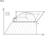
- Fig. 2 shows in a schematic and simplified log(p)-h diagram the refrigeration cycle process and the effects associated with the post-heating process presented here in purely qualitative terms.
- the cycle process runs counterclockwise.
- the cycle shown with the solid line L_g illustrates the problem that, with small excess power, the refrigerant in the external heat exchanger 18 is almost completely or predominantly in the two-phase state of aggregation. This is indicated by the arrow A pointing to the isobaric curve. Pressure is reduced via the expansion valve AE2 and it is clear from the solid cycle that a lack of refrigerant can occur on the low-pressure side, which leads to an overheated discharge of refrigerant at the evaporator 22, which is illustrated by point B. This can, for example, affect the air-side temperature at the evaporator 22, so that the interior comfort in the vehicle is negatively affected. In other words, there are high temperature spreads in the supply air after the evaporator 22, which leads to a loss of comfort.
- oil deposits can also occur in the refrigerant reservoir 24. Due to the absence or a strong reduction of a liquid phase of refrigerant in the refrigerant reservoir 24, increased amounts of oil can remain in the refrigerant reservoir 24 and is no longer supplied to the compressor 12, which can lead to lubrication problems in the compressor 12.
- the power or heat to be dissipated at the external heat exchanger 18 also increases, so that the coolant is present at its inlet to a significantly greater extent or, with an increasing proportion, in two-phase form. This is illustrated in the dashed cycle at point C, which is shifted from left to right by the load increase. Accordingly, the There is now sufficient refrigerant available on the low-pressure side of the refrigeration system 10 for the evaporator 22 and/or the chiller 28 and/or a rear evaporator. Accordingly, the refrigerant reservoir 24 also contains a sufficient amount of liquid refrigerant so that the above-described problem of temperature inhomogeneity on the air side and the inadequate lubrication of the compressor 12 does not occur.
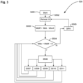
- Fig. 3 shows a simplified reheating method 500, in which the refrigeration system 10 is set so that the refrigerant flow flows as described above from the compressor via the heating register 26, the expansion valve AE4, the external heat exchanger 18, the internal heat exchanger 20, the expansion valve AE3, at least the evaporator 22 and finally to the refrigerant storage tank 24.
- a transition to a reheating mode which is referred to here as Reheat III (S502), takes place at a point in time not specified here.
- a possible condition that must be met in order to start the reheating mode (S502) can be, for example, the measured ambient temperature.
- the reheating method can be activated in particular when the ambient temperature is up to 15°C, in particular from about 5°C to 15°C.
- At least one operating setting of the refrigeration system 10 is adjusted so that the load in the refrigeration system 10 is increased if the condition in S504 is met. If the condition in S504 is not met, i.e. there is either a power deficit or a large power surplus, the reheating process branches to a step S505, which represents the process steps SRH to be carried out under these conditions, but which are not described in more detail here.
- Adjusting the operating setting includes step S507: measuring the temperature of the supply air after it has flowed through the evaporator 22 and lowering a target temperature SP T_Verd for the temperature of the supply air to the heating register after it has flowed through the evaporator 22.
- the lowering of the target temperature SP T_Verd can be carried out until a minimum permissible target temperature is reached. This can in particular be carried out repeatedly and/or step by step.
- Adjusting the operating setting may include step S508: adjusting the condition or quality of the supply air (L) supplied to the evaporator 22, whereby the proportion of recirculated air in the supply air is increased, provided, of course, that its admixture causes the desired load increase on the evaporator by an increase in the enthalpy in the supply air flow to the evaporator.
- the adjustment of the operating setting can comprise step S509: integration of at least one further component of the refrigeration system 10 arranged in flow parallel or, in special cases, in series with the evaporator 22, in particular the chiller 28 operating as a water heat pump evaporator and/or the rear evaporator 22h for the air conditioning of a rear vehicle area.
- Adjusting the operating setting may include step S510: increasing the amount of air passed through the heating register 22.
- Adjusting the operating setting can include step S511: reducing the supply air flow via the external heat exchanger 18.
- the external heat exchanger 18 can also be referred to as a cooling package with the integrated components condenser 18 or gas cooler 18.
- the reduction in the supply air flow can be achieved by means of a closable and/or continuously adjustable cooling air inlet and/or reduction in the fan control, which leads to a reduction in the amount of air drawn in from the environment.
- the steps S507 to S511 can be carried out individually or in any combination to achieve the desired result of increased power consumption. If the desired result of increased power surplus is achieved by possibly executing one of the steps S507 to S511 several times or a combination of several of these steps S507 to S511, the condition in step S504 is no longer fulfilled, so that the reheating method 500 branches to step S505, which represents a state of the refrigeration system 10 in which there is no risk of a lack of refrigerant, in particular in the liquid state, on the low-pressure side or in the refrigerant collector 24 and in the reheating method 500 in particular steps S507 to S511 do not have to be carried out.
- step S505 represents a state of the refrigeration system 10 in which there is no risk of a lack of refrigerant, in particular in the liquid state, on the low-pressure side or in the refrigerant collector 24 and in the reheating method 500 in particular steps S507 to S511 do not have to be carried out.
Landscapes
- Engineering & Computer Science (AREA)
- Physics & Mathematics (AREA)
- Thermal Sciences (AREA)
- Mechanical Engineering (AREA)
- General Engineering & Computer Science (AREA)
- Air-Conditioning For Vehicles (AREA)
Description
- Die Erfindung betrifft ein Nachheizverfahren (RHIII) zum Betreiben einer Kälteanlage mit Wärmepumpenfunktion für ein Kraftfahrzeug, eine Kälteanlage und ein Kraftfahrzeug mit einer solchen Kälteanlage. Insbesondere umfasst das Nachheizverfahren Schritte, die dazu eingerichtet sind, das Kältemittelmanagement im Rahmen bestimmter Betriebsbedingungen der Kälteanlage zu optimieren.
- Eine Kälteanlage mit Wärmepumpenfunktion umfasst üblicherweise einen Kältemittelverdichter, der mit einem Primärstrang und einem Sekundärstrang verbindbar oder verbunden ist; einen äußeren Wärmeübertrager, der im Primärstrang angeordnet ist; einen Verdampfer, der im Primärstrang angeordnet ist; ein Heizregister, das im Sekundärstrang angeordnet ist; wenigstens eine bewegliche Temperaturklappe, die bezogen auf eine Zuluftströmungsrichtung vor oder nach dem Heizregister angeordnet ist; und wenigstens ein Nachheiz-Expansionsventil, das zwischen dem Heizregister und dem äußeren Wärmeübertrager im Sekundärstrang angeordnet ist.
- Eine derartige Kälteanlage mit Wärmepumpenfunktion ist beispielsweise in der
DE 10 2018 207 049 A1 oder derDE 10 2018 213 232.1 beschrieben, die zum Zeitpunkt der Einreichung der vorliegenden Anmeldung noch nicht veröffentlicht war. - Weitere Hintergrundinformationen zu Kälteanlagen bzw. Wärmepumpen finden sich beispielsweise in den Druckschriften
DE 10 2016 005 782 A1 ,US 10 391 836 B2 US 2017/182860 A1 ,FR 3 073 175 A1 DE 10 2015 210 414 A1 ,DE 10 2011 118 162A1 undDE 10 2015 002 166 A1 . - Bei einem Nachheizverfahren, das im Fachjargon auch als Reheat, Reheat-Betrieb, Reheat-Verfahren bezeichnet wird, wird bei der Klimatisierung eines Fahrzeuginnenraums die durch den Verdampfer gekühlte und entfeuchtete Luft durch wenigstens teilweise Erwärmung mittels des Heizregisters auf eine gewünschte Ausblastemperatur gebracht.
- Das Heizregister ist dabei eine Wärmequelle, bei der im Kältemittel gespeicherte Wärme an ein anderes Medium, wie Luft, Wasser, Wasser-Glykol-Gemisch und dergleichen abgegeben wird. Das Heizregister kann als Heizkondensator bzw. Heizgaskühler ausgeführt sein, wenn es direkt von (Umgebungs-)Luft als Kabinenzuluft durch- bzw. umströmt wird, welche die abgegebene Wärme aufnimmt. Das Heizregister kann als Fluid-Wärmeübertrager ausgeführt sein, wenn es von einem anderen Fluid als (Umgebungs-)Luft, wie beispielsweise Wasser, Wasser-Glykol-Gemisch oder dergleichen durch- bzw. umströmt wird, wobei die im Kältemittel gespeicherte Wärme an das Fluid abgegeben wird. Bei der Ausgestaltung als Fluid-Wärmeübertrager erfolgt dann ein weiterer Wärmeaustausch vom erwärmten Fluid auf die (Umgebungs-)Luft. Insoweit erfolgt durch einen Fluid-Wärmeübertrager eine indirekte Erwärmung von (Umgebungs-)Luft.
- Bei einem Nachheiz- bzw. Reheatbetrieb kann über eine Regelung des Nachheiz-Expansionsventils die gewünschte Leistung zur Heizung eines Fahrzeuginnenraums eingestellt werden. Ein möglicher Kennwert für die Wärmeabgabe bzw. die Heizleistung kann dabei eine Ausblastemperatur von konditionierter Luft in den Fahrzeuginnenraum sein.
- Wird ein Wärme- bzw. Heizleistungsüberschuss ermittelt, wobei beispielsweise die Ist-Ausblastemperatur größer ist als eine Soll-Ausblastemperatur, kann das Nachheizexpansionsventil insbesondere schrittweise geöffnet werden. Hierdurch sinkt beim Heizregister der Hochdruck und es stellt sich am äußeren Wärmeübertrager ein (steigender) Mittel- bzw. Zwischendruck ein.
- Entsprechend steigt die Kondensationstemperatur und der Temperaturunterschied zur Umgebung erhöht sich, so dass über den äußeren Wärmeübertrager mehr Wärme an die Umgebung abgegeben wird.
- Wird ein Wärme- bzw. Heizleistungsdefizit ermittelt, wobei beispielsweise die Ist-Ausblastemperatur kleiner als die Soll-Ausblastemperatur ist, kann das Nachheiz-Expansionsventil insbesondere schrittweise geschlossen werden. Hierdurch steigt beim Heizregister der Hochdruck und beim äußeren Wärmeübertrager sinkt der Mittel- bzw. Zwischendruck. Entsprechend sinkt die Kondensationstemperatur und der Temperaturunterschied zur Umgebung verringert sich, so dass über den äußeren Wärmeübertrager weniger Wärme an die Umgebung abgegeben wird.
- Es hat sich gezeigt, dass sich bei geringen Wärme- bzw. Heizleistungsüberschüssen folgende Situation in der Kälteanlage ergeben kann. Im äußeren Wärmeübertrager liegt das Kältemittel nahezu vollständig in flüssiger Form vor. Entsprechend kann es auf der Niederdruckseite der Kälteanlage, also stromabwärts des Verdampfers, zu einem Kältemittelmangel kommen, was zu einem überhitzten Austritt von Kältemittel aus dem Verdampfer führt.
- Eine solche Überhitzung kann sich beispielsweise auf die luftseitige Temperatur am Verdampfer auswirken, so dass hierdurch der Innenraumkomfort im Fahrzeug negativ beeinflusst wird. Mit anderen Worten ergeben sich hohe Temperaturspreizungen im Abluftstrom des Verdampfers, was zu den Komforteinbußen aufgrund Temperaturinhomogenität aber auch schlechterer Entfeuchtungsleistung führt.
- Ferner kann es je nach Ausgestaltung der Kälteanlage auch zu Öleinlagerungen im Kältemittelspeicher kommen. Aufgrund des Fehlens oder einer starken Reduktion einer flüssigen Phase von Kältemittel im Kältemittelspeicher kann das Öl im Kältemittelspeicher zurückbleiben und wird nicht mehr dem Verdichter zugeführt, was zu Schmierungsproblemen am Verdichter führen kann.
- Die der Erfindung zu Grunde liegende Aufgabe wird darin gesehen, ein Nachheizverfahren anzugeben, bei dem die obigen Nachteile vermieden werden können.
- Diese Aufgabe wird gelöst durch ein Nachheizverfahren mit den Merkmalen des Patentanspruchs 1, durch eine Kälteanlage mit den Merkmalen des Patentanspruchs 7 und durch ein Kraftfahrzeug mit den Merkmalen des Anspruch 11. Vorteilhafte Ausgestaltungen mit zweckmäßigen Weiterbildungen sind in den abhängigen Patentansprüchen angegeben.
- Vorgeschlagen wird also ein Nachheizverfahren zum Betreiben einer Kälteanlage mit Wärmepumpenfunktion für ein Kraftfahrzeug, wobei die Kälteanlage umfasst:
- einen Kältemittelverdichter, der mit einem Primärstrang und einem Sekundärstrang verbindbar oder verbunden ist;
- einen äußeren Wärmeübertrager, der im Primärstrang angeordnet ist;
- einen Verdampfer, der im Primärstrang angeordnet ist;
- ein Heizregister, das im Sekundärstrang angeordnet ist;
- wenigstens ein Nachheiz-Expansionsventil, das zwischen dem Heizregister und dem äußeren Wärmeübertrager im Sekundärstrang angeordnet ist. Dabei umfasst das Nachheizverfahren folgende Schritte:
Bestimmen eines Wärmedifferenzwerts durch Vergleichen eines Wärmeabgabe-Istwerts am Heizregister mit einem Wärmeabgabe-Sollwert, Anpassen von wenigstens einer Betriebseinstellung der Kälteanlage, so dass die Lastaufnahme in der Kälteanlage erhöht wird, wenn der Wärmedifferenzwert größer als 0 und kleiner als ein Wärmedifferenzschwellwert ist. - Dabei können der Wärmeabgabe-Istwert und der Wärmeabgabe-Sollwert beispielsweise anhand von gemessener bzw. vorgegebener Ausblastemperatur von konditionierter Zuluft in den Fahrzeuginnenraum festgelegt sein. Der Wärmeabgabe-Istwert und der Wärmeabgabe-Sollwert können aber auch anhand anderer messbarer Größen bzw. Parameter der Kälteanlage bestimmt werden bzw. sein. Insbesondere können sie auch aus einer Kombination von zur Verfügung stehenden Kälteanlagen- bzw. Klimatisierungsparametern bestimmt werden bzw. sein.
- Der Wärmedifferenzschwellwert kann dabei so festgelegt sein, dass er einen geringen Wärme- bzw. Heizleistungsüberschuss repräsentiert. Geht man beispielsweise davon aus, dass der Wärmedifferenzwert ausgehend von einer Ist-Ausblastemperatur und einer Soll-Ausblastemperatur berechnet wird, kann der Wärmedifferenzschwellwert beispielsweise bei 5 oder kleiner angesetzt werden, aber größer als 0 sein.
- Bei dem Nachheizverfahren umfasst das Anpassen der Betriebseinstellung: Messen der Temperatur der Zuluft nach dem Durchströmen des Verdampfers und Absenken einer Solltemperatur für die Temperatur der Zuluft nach dem Durchströmen des Verdampfers.
- Das Einstellen der Solltemperatur der Luft nach dem Verdampfer wird auch als Variation des Setpoints der Lufttemperatur nach dem Verdampfer bezeichnet. Wird die zu erreichende Solltemperatur der Luft nach dem Verdampfer reduziert, wird stärker gekühlte Luft bereitgestellt, und die Leistungsaufnahme im Gesamtsystem der Kälteanlage wird erhöht.
- Das Absenken der Solltemperatur kann bis zum Erreichen einer minimalen Solltemperatur durchgeführt werden, insbesondere kann diese Maßnahme wiederholt oder/und schrittweise durchgeführt werden. Dabei kann die Solltemperatur beispielsweise auf einen zulässigen Wert von minimal 2 bis 4°C eingestellt werden, um eine Vereisung des Verdampfers durch auskondensierendes Wasser aus dem Verdampferzuluftstrom zu verhindern.
- Bei dem Nachheizverfahren kann das Anpassen der Betriebseinstellung alternativ oder ergänzend umfassen: Einstellen der Kondition oder Güte der zum Verdampfer zugeführten Zuluft, wobei der Umluftanteil in der Zuluft erhöht wird. Wird dem Verdampfer wärmere Zuluft zugeführt, was durch das Beimischen von bereits erwärmter Umluft aus dem Fahrzeuginneren erfolgen kann, muss der Verdampfer eine höhere Kühlleistung erbringen, was zu einer gesteigerten Leistungsaufnahme im Gesamtsystem der Kälteanlage führt.
- Bei dem Nachheizverfahren kann das Anpassen der Betriebseinstellung alternativ oder ergänzend umfassen: Einbinden von wenigstens einer weiteren, strömungstechnisch parallel oder in Reihe zum Verdampfer angeordneten Komponente der Kälteanlage, insbesondere eines als Wasserwärmepumpeverdampfer arbeitenden Chillers oder/und eines Heckverdampfers für die Klimatisierung eines hinteren Fahrzeugbereichs. Der Chiller dient dabei üblicherweise der Kühlung einer elektrischen Komponente des Fahrzeugs, wie etwa einer Batterie. Der Heckverdampfer kann in einem Fahrzeug vorhanden sein, aber beispielsweise aufgrund der Anzahl Fahrzeuginsassen deaktiviert sein, weil der hintere Fahrzeugbereich (Fond) nicht speziell klimatisiert werden soll. Um die Lastaufnahme insgesamt zu steigern, kann einer solcher Heckverdampfer mit eingebunden werden.
- Bei dem Nachheizverfahren kann das Anpassen der Betriebseinstellung alternativ oder ergänzend umfassen: Erhöhen der Luftmenge, die durch das Heizregister geführt wird.
- Bei dem Nachheizverfahren kann das Anpassen der Betriebseinstellung alternativ oder ergänzend umfassen: Verringern des Zuluftstroms über den äußeren Wärmeübertrager.
- Durch die Einstellung der Menge an zugeführter Zuluft am Heizregister oder/und am äußeren Wärmeübertrager, kann die Leistungsaufnahme des Gesamtsystems der Kälteanlage in gewünschter Weise beeinflusst werden.
- Die oben erwähnten Anpassungen der Betriebseinstellung dienen jeweils alleine oder in beliebigen Kombinationen miteinander dazu, die Leistungsaufnahme des Gesamtsystems zu erhöhen. Hierdurch steigt die am äußeren Wärmeübertrager abzuführende Leistung. Insbesondere liegt am Eintritt des äußeren Wärmeübertragers das Kältemittel zu einem größeren Anteil gasförmig vor. Entsprechend führt dies dazu, dass an dem Verdampfer ausreichend Kältemittel zur Verfügung steht, so dass damit aber auch in den systemseitig vorgesehenen Kältemittelspeichern ausreichend Kältemittel vorliegt.
- Es wird ferner eine Kälteanlage mit Wärmepumpenfunktion für ein Kraftfahrzeug vorgeschlagen,
- mit einem Kältemittelverdichter, der mit einem Primärstrang und einem Sekundärstrang verbindbar oder verbunden ist;
- einem äußeren Wärmeübertrager, der im Primärstrang angeordnet ist;
- einem Verdampfer, der im Primärstrang angeordnet ist;
- einem Heizregister, das im Sekundärstrang angeordnet ist;
- wenigstens einem Nachheiz-Expansionsventil, das zwischen dem Heizregister und dem äußeren Wärmeübertrager im Sekundärstrang angeordnet ist;
- und einem Steuergerät, das dazu eingerichtet ist, die Kälteanlage mit einem Nachheizverfahren nach einem der vorhergehenden Ansprüche zu betreiben,
- wobei in einem solchen Nachheizbetrieb das Kältemittel ausgehend vom Kältemittelverdichter nacheinander die folgenden Komponenten der Kälteanlage durchströmt: Heizregister und Nachheiz-Expansionsventil im Sekundärstrang, äußerer Wärmeübertrager und Verdampfer im Primärstrang.
- Die Kälteanlage kann einen strömungstechnisch parallel zum Verdampfer angeordneten Chiller oder/und einen strömungstechnisch parallel zum Verdampfer angeordneten Heckverdampfer umfassen. Alternativ können diese zusätzlichen Verdampfer jedoch auch in einer Reihenverschaltung bezogen auf den Hauptverdampfer angeordnet sein.
- Die Kälteanlage kann mit wenigstens einer beweglichen Temperaturklappe ausgeführt sein, die bezogen auf eine Zuluftströmungsrichtung vor oder nach dem Heizregister angeordnet ist.
- Die Kälteanlage kann wenigstens eine bewegliche Zuluftklappe aufweisen, die bezogen auf eine Zuluftströmungsrichtung vor dem Verdampfer angeordnet ist.
- Die Temperaturklappe(n) oder/und die Zuluftklappe(n) kann bzw. können Teil eines Klimageräts sein, in dem die für die Konditionierung des Zuluftstroms zur Kabine wirkenden Wärmeübertrager aufgenommen sind.
- Ein Kraftfahrzeug kann mit einer oben beschriebenen Kälteanlage ausgestattet sein. Dabei kann es sich bei dem Kraftfahrzeug insbesondere um ein Elektrofahrzeug handeln. Bei einem Elektrofahrzeug kann der effiziente Betrieb der Kälteanlage zu Stromeinsparungen führen, so dass hierdurch eine größere Reichweite des Elektrofahrzeugs erzielt werden kann. Insbesondere kann durch die oben beschriebenen Maßnahmen das Einsatzfenster eines Nachheizbetriebs, insbesondere eines Wärmepumpen-Reheat-Betriebs, vergrößert werden, so dass ein solcher Nachheizbetrieb häufiger eingesetzt werden kann. Hierdurch ergibt sich eine verringerte durchschnittliche elektrische Leistungsaufnahme, weil üblicherweise erst viel später oder gegebenenfalls auch gar nicht ein elektrischer Zuheizer eingeschaltet werden muss.
- Weitere Vorteile und Einzelheiten der Erfindung ergeben sich aus der nachfolgenden Beschreibung von Ausführungsformen unter Bezugnahme auf die Figuren. Dabei zeigt:
- Fig. 1
- ein schematisches und vereinfachtes Schaltbild einer Kälteanlage für ein Kraftfahrzeug;
- Fig. 2
- ein vereinfachtes log(p)-h-Diagramm zur Veranschaulichung des Kreisprozesses im Nachheizbetrieb.
- Fig. 3
- ein Flussdiagram einer beispielhaften Umsetzung des Nachheizverfahrens, insbesondere mittels der in
Fig. 1 beschriebenen Kälteanlage. - In
Fig. 1 ist eine Ausführungsform einer Kälteanlage 10 für ein Kraftfahrzeug schematisch und vereinfacht dargestellt. Die Kälteanlage 10 umfasst einen Kältemittelkreislauf 11, der sowohl in einem Kälteanlagenbetrieb (kurz auch AC-Betrieb genannt), als auch in einem Wärmepumpenmodus betrieben werden kann. Die Kälteanlage 10 umfasst in der gezeigten Ausführungsform einen Kältemittelverdichter 12, einen äußeren Wärmeübertrager 18, einen inneren Wärmeübertrager 20, einen Verdampfer 22 und einen Akkumulator bzw. Kältemittelsammler 24. Der äußere Wärmeübertrager 18 kann als Kondensator oder Gaskühler ausgebildet sein. Insbesondere ist der äußere Wärmeübertrager 18 in der dargestellten Ausführungsform bidirektional durchströmbar. - Der Verdampfer 22 ist hier beispielhaft als Frontverdampfer für ein Fahrzeug gezeigt. Der Verdampfer 22 steht stellvertretend auch für weitere in einem Fahrzeug mögliche Verdampfer, wie beispielsweise Fondverdampfer, die strömungstechnisch parallel zueinander angeordnet sein können. Mit anderen Worten umfasst die Kälteanlage 10 also wenigstens einen Verdampfer 22.
- Stromabwärts des Verdichters 12 ist ein Absperrventil A4 angeordnet. Stromaufwärts des Verdampfers 22 ist ein Expansionsventil AE2 vorgesehen.
- Im Rahmen dieser Beschreibung wird in dem gesamten Kältemittelkreislauf 11 der Kälteanlage 10 der Abschnitt vom Verdichter 12 zum äußeren Wärmeübertrager 18, zum inneren Wärmeübertrager 20 und zum Verdampfer 22 als Primärstrang 14 bezeichnet.
- Die Kälteanlage 10 umfasst weiter ein Heizregister 26 (auch als Heizkondensator oder Heizgaskühler bezeichnet). Stromaufwärts des Heizregisters 26 ist ein Absperrventil A3 angeordnet. Stromabwärts des Heizregisters 26 ist ein Absperrventil A1 angeordnet. Ferner ist stromabwärts des Heizregisters 26 ein Expansionsventil AE4 angeordnet.
- Im Rahmen dieser Beschreibung wird in dem gesamten Kältemittelkreislauf der Kälteanlage 10 der Abschnitt vom Verdichter 12 zum Heizregister 26, zum Expansionsventil AE4 und zu einem Abzweig Ab2 als Sekundärstrang 16 bezeichnet. Der Sekundärstrang 16 umfasst einen Heizzweig 16.1, der sich von dem Absperrventil A3 über das Heizregister 26 zum Absperrventil A1 erstreckt. Weiter umfasst der Sekundärstrang 16 einen Nachheizzweig bzw. Reheat-Zweig 16.2, der stromaufwärts mit dem Heizregister 26 und stromabwärts mit dem äußeren Wärmeübertrager 5 fluidverbindbar ist. Dabei mündet der Sekundärstrang 16 bzw. der Reheat-Zweig 16.2 bei einem Abzweigpunkt Ab2 in den Primärstrang 14.
- Die Kälteanlage 10 umfasst einen weiteren Verdampfer bzw. Chiller 28. Der Chiller 28 ist strömungstechnisch parallel zum Verdampfer 22 vorgesehen. Der Chiller 28 kann beispielsweise zur Kühlung einer elektrischen Komponente des Fahrzeugs dienen, aber auch zur Realisierung einer Wasser-Wärmepumpenfunktion unter Nutzung der Abwärme von wenigstens einer elektrischen Komponente. Dem Chiller 28 ist stromaufwärts ein Expansionsventil AE1 vorgeschaltet.
- Die Kälteanlage 10 kann auch ein elektrisches Heizelement 30 aufweisen, das beispielsweise als Hochvolt-PTC-Heizelement ausgeführt ist. Das elektrische Heizelement 30 dient als Zusatzheizer für einen in den Fahrzeuginnenraum geführten Zuluftstrom L. Dabei kann das elektrische Heizelement 30 zusammen mit dem Heizregister 26 und dem Verdampfer 22 in einem Klimagerät 32 untergebracht sein. Dabei kann das elektrische Heizelement 30 dem Heizregister 26 nachgeschaltet angeordnet sein.
- In der
Fig. 1 sind ferner noch Rückschlagventile R1 und R2 ersichtlich. Ferner sind auch einige Sensoren pT1 bis pT5 zur Erfassung von Druck oder/und Temperatur des Kältemittels dargestellt. Es wird darauf hingewiesen, dass die Anzahl der Sensoren bzw. deren Anordnung hier nur beispielhaft gezeigt ist. Eine Kälteanlage 10 kann auch weniger oder mehr Sensoren aufweisen. Im gezeigten Beispiel sind als Sensoren kombinierte Druck/Temperatursensoren pT1 bis pT5 gezeigt. Es ist aber genauso denkbar, dass voneinander getrennte Sensoren für die Messung von Druck bzw. Temperatur eingesetzt werden und ggf. auch räumlich voneinander getrennt entlang den Kältemittelleitungen angeordnet sind. - Die Kälteanlage 10 kann in unterschiedlichen Modi betrieben werden, die nachfolgend kurz beschrieben werden.
- Im AC-Betrieb des Kältemittelkreislaufs 11 strömt das auf Hochdruck verdichtete Kältemittel ausgehend von dem Kältemittelverdichter 12 bei offenem Absperrventil A4 in den äußeren Wärmeübertrager 18. Von dort strömt es zu dem Hochdruckabschnitt des inneren Wärmeübertragers 20 und dem vollständig geöffneten Expansionsventil AE3. Über einen Abzweigpunkt Ab1 kann das Kältemittel zum Expansionsventil AE2 und in den Innenraum-Verdampfer 22 strömen (Verdampferabschnitt 22.1). Parallel oder alternativ kann das Kältemittel über einen Abzweigpunkt Ab4 und das Expansionsventil AE1 in den Chiller 28 strömen (Chillerabschnitt 28.1). Aus dem Verdampfer 22 oder/und dem Chiller 28 strömt das Kältemittel niederdruckseitig in den Sammler 24 und durch den Niederdruckabschnitt des inneren Wärmeübertragers 20 zurück zum Verdichter 12.
- In dem AC-Betrieb ist der Heizzweig 16.1 bzw. der Sekundärstrang 16 mittels des Absperrventils A3 abgesperrt, so dass heißes Kältemittel nicht durch das Heizregister 26 strömen kann. Zur Rückholung von Kältemittel aus dem inaktiven Heizzweig 16.1 kann das als Absperrventil ausgebildete Absperrorgan A5 geöffnet werden, so dass das Kältemittel über das Absperrorgan A5 und das Rückschlagventil R2, bei gleichzeitig geschlossenem Absperrorgan A2, in Richtung des Sammlers 24 strömen kann.
- Im Heizbetrieb des Kältemittelkreislaufs 11 wird das Absperrventil A4 geschlossen und das Absperrventil A3 geöffnet, so dass heißes Kältemittel in den Heizzweig 16.1 strömen kann.
- Zur Durchführung der Heizfunktion mittels des Chillers 28 zur Realisierung eines Wasser-Wärmepumpen-Betriebs strömt das mittels des Kältemittelverdichters 12 verdichtete Kältemittel über das geöffnete Absperrventil A3 in das Heizregister 26 . Am Heizregister 26 wird Wärme an einen in den Fahrzeuginnenraum geführten Zuluftstrom L abgegeben. Das Kältemittel strömt anschließend über das geöffnete Absperrventil A1 und den Abzweigpunkt Ab1.
- Es wird mittels des Expansionsventils AE1 in den Chiller 28 zur Aufnahme von Abwärme der in einem Kühlmittelkreislauf 28.2 angeordneten elektrischen und/oder elektronischen Komponenten entspannt. Bei dieser Heizfunktion sind die Expansionsventile AE3 und AE4 geschlossen, das Absperrventil A5 geschlossen und das Absperrventil A2 geöffnet. Dabei kann über das Absperrventil A2 im Wasser-Wärmepumpenbetrieb ausgelagertes Kältemittel aus einem Bidirektionalzweig 14.1 bzw. dem Primärstrang 14 abgesaugt und über das Rückschlagventil R2 dem Sammler 24 zugeführt werden.
- Zur Durchführung der Heizfunktion mittels des äußeren Wärmeübertragers 18 als Wärmepumpenverdampfer strömt das mittels des Kältemittelverdichters 12 verdichtete Kältemittel über das geöffnete Absperrventil A3 zur Abgabe von Wärme an einen Zuluftstrom L in das Heizregister 26. Anschließend wird es über das geöffnete Absperrventil A1 mittels des Expansionsventils AE3 in den äußeren Wärmeübertrager 18 zur Aufnahme von Wärme aus der Umgebungsluft entspannt. Danach strömt das Kältemittel über einen Wärmepumpenrückführzweig 15 zum Sammler 24 und zurück zum Kältemittelverdichter 12. Die Expansionsventile AE1, AE2 und AE4 bleiben dabei, ebenso wie das Absperrventil A5, geschlossen.
- Eine indirekte Dreiecksschaltung kann dadurch realisiert werden, dass bei geöffnetem Absperrventil A1 das von dem Kältemittelverdichter 12 verdichtete Kältemittel mittels des Expansionsventils AE1 in den Chiller 28 entspannt wird, wobei gleichzeitig kühlmittelseitig, also in dem Kühlmittelkreislauf 28.2 kein Massenstrom erzeugt wird, also bspw. das als Kühlmittel verwendete Fluid, wie etwa Wasser oder Wasser-Glykol-Gemisch, auf der Kühlmittelseite des Chillers 28 stehen bleibt bzw. der Chiller 28 nicht aktiv von Kühlmittel durchströmt wird. Die Expansionsventile AE2, AE3 und AE4 bleiben bei dieser Schaltvariante geschlossen.
- Bei einem Nachheiz- bzw- Reheat-Betrieb wird der in den Fahrzeuginnenraum zugeführte Zuluftstrom L mittels des Verdampfers 22 zunächst gekühlt und damit entfeuchtet. Mit der dem Kältemittel über den Verdichter 12 zugeführten Wärme kann der Zuluftstrom L mittels des Heizregisters 26 zumindest teilweise wieder erwärmt werden.
- Hierzu weist die Kälteanlage 10, insbesondere das Klimagerät 32, zwischen dem Verdampfer 22 und dem Heizregister 26 einstellbare, insbesondere steuerbare und schwenkbare, Temperaturklappen 34 auf. Im dargestellten Beispiel sind eine linke und eine rechte Temperaturklappe 34L und 34R (in
Figur 1 schematisch dargestellt) angeordnet. Die Temperaturklappen 34L, 34R können zwischen einer Offenposition, die als 100%-Position bezeichnet wird, und einer Schließposition, die als 0%-Position bezeichnet wird, eingestellt bzw. verschwenkt werden. Alternativ ist es auch möglich, die Temperaturklappen 34R, 34L dem Heizregister 26 nachzuschalten. - In der 100%-Position wird der gesamte den Verdampfer 22 durchströmende Zuluftstrom L über das Heizregister 26 geführt und erwärmt, bevor dieser in den Fahrgastraum des Fahrzeugs strömen kann. In der 0%-Position strömt der gesamte den Verdampfer 22 durchströmende Zuluftstrom L im Bypass um das Heizregister 26 ohne Erwärmung und damit ohne Wärmeaufnahme in den Fahrgastraum.
- In einer x-Position der Temperaturklappen 34L und 34R mit 0 % < x < 100 % sind diese Temperaturklappen nur teilweise geöffnet, so dass jeweils nur ein Teilluftstrom des den Verdampfer 22 durchströmenden Zuluftstroms L über das Heizregister 26 geführt wird. Dieser erwärmte Teilluftstrom kann anschließend dem verbleibenden, gekühlten und entfeuchteten Teilluftstrom beigemischt werden. Der in dieser Weise erwärmte Zuluftstrom L wird dem Fahrgastraum des Fahrzeugs zugeführt. Beispielhaft zeigt eine 50 %-Position an, dass die Temperaturklappen 34R und 34L nur halb, also 50 % geöffnet sind.
- Ein strömungstechnisch zum Verdampfer 22 parallel angeordneter Heckverdampfer 22h ist eine optionale Komponente in einer Kälteanlage 10. Der Heckverdampfer 22h dient insbesondere dazu, einen hinteren Bereich (Fond) des Kraftfahrzeugs zu klimatisieren. Der Heckverdampfer 22h kann beispielsweise beim Abzweigpunkt Ab1 angeschlossen sein. Dem Heckverdampfer 22h ist ein eigenes Expansionsventil AE5 zugeordnet, insbesondere stromaufwärts von dem Heckverdampfer 22h angeordnet. Stromabwärts des Heckverdampfers 22h kann ein weiteres Rückschlagventil R3 angeordnet sein. Schließlich ist der Heckverdampfer 22 stromabwärts des Rückschlagventils R1 mit der niederdruckseitigen Zufuhrleitung zum Kältemittelsammler verbunden.
- Ein Nachheiz- bzw. Reheat-Betrieb des Kältemittelkreislaufs 11 bzw. der Kälteanlage 10 wird in Abhängigkeit der Wärmebilanz auf unterschiedliche Weise durchgeführt.
- Nachfolgend wird ein für den Nachheiz- bzw. Reheatbetrieb mögliches Betriebsverfahren 500 anhand des Ablaufschemas der
Fig. 2 und unter Bezugnahme auf die inFig. 1 dargestellte Kälteanlage 10 und ihrer Komponenten beispielhaft erläutert. Ein solches Betriebsverfahren ist üblicherweise in einem Steuergerät für die Kälteanlage bzw. für die Klimatisierung in einem Fahrzeug als Steuerprogramm umgesetzt. - Betrachtet wird ein Nachheizbetrieb, bei dem das Kältemittel ausgehend von dem Verdichter 12 über das geöffnete Absperrventil A3 zum Heizregister 26 (Heizkondensator bzw. Heizgaskühler) strömt Das Absperrventil A1 ist geschlossen und das Kältemittel strömt über das Expansionsventil AE4 zum äußeren Wärmeübertrager 18. Danach passiert das Kältemittel hochdruckseitig den inneren Wärmeübertrager 20 und gelangt über das geöffnete Expansionsventil AE3 und das Expansionsventil AE2 zum Verdampfer 22. Von dort gelangt das Kältemittel über den Kältemittelsammler 24 und den niederdruckseitigen Abschnitt des inneren Wärmeübertragers 20 wieder zum Verdichter 12. Bei diesem Nachheizverfahren können die Temperaturklappen 34L, 34R in geeignete Stellungen bewegt werden, die einen Wert von 0% (Temperaturklappen 34L, 34R geschlossen) bis 100% (Temperaturklappen 34L, 34R vollständig geöffnet) annehmen können.
-
Fig. 2 zeigt in einem schematischen und vereinfachten log(p)-h-Diagramm rein qualitativ den Kältekreisprozess und die mit dem hier vorgestellten Nachheizverfahren verbundenen Wirkungen. Der Kreisprozess wird im Gegenuhrzeigersinn durchlaufen. - Der mit durchgezogener Linie L_g dargestellte Kreisprozess illustriert die Problematik, dass bei geringen Leistungsüberschüssen das Kältemittel im äußeren Wärmeübertrager 18 nahezu vollständig bzw. Überwiegend im zweiphasigen Aggregatszustand vorliegt. Dies ist durch den auf den isobaren Verlauf gerichteten Pfeil A gekennzeichnet. Über das Expansionsventil AE2 wird Druck abgebaut und es ist aus dem durchgezogen dargestellten Kreisprozess ersichtlich, dass sich auf der Niederdruckseite, ein Mangel an Kältemittel einstellen kann, was zu einem überhitzten Austritt von Kältemittel am Verdampfer 22 führt, was durch den Punkt B illustriert ist. Dies kann sich beispielsweise auf die luftseitige Temperatur am Verdampfer 22 auswirken, so dass hierdurch der Innenraumkomfort im Fahrzeug negativ beeinflusst wird. Mit anderen Worten ergeben sich hohe Temperaturspreizungen der Zuluft nach dem Verdampfer 22, was zu Komforteinbußen führt.
- Ferner kann es, je nach Ausgestaltung der Kälteanlage 10, auch zu Öleinlagerungen im Kältemittelspeicher 24 kommen. Aufgrund des Fehlens oder einer starken Reduktion einer flüssigen Phase von Kältemittel im Kältemittelspeicher 24 kann verstärkt Öl im Kältemittelspeicher 24 zurückbleiben und wird nicht mehr dem Verdichter 12 zugeführt, was zu Schmierungsproblemen am Verdichter 12 führen kann.
- Wird die Leistungsaufnahme der Kälteanlage 10 erhöht, so dass ein größerer bzw. höherer Leistungsüberschuss entsteht, was durch den gestrichelt dargestellten Kreisprozess L_h vereinfacht illustriert ist, steigt auch die am äu-ßeren Wärmeübertrager 18 abzuführende Leistung bzw. Wärme, so dass an dessen Einritt das Kältemittel zu einem deutlich größeren Anteil bzw., mit einem zunehmenden Anteil zweiphasig vorhanden ist. Dies ist in dem gestrichelten Kreisprozess bei Punkt C illustriert, der quasi durch die Lastanhebung von links nach rechts verschoben wird. Entsprechend steht auf der Niederdruckseite der Kälteanlage 10 nun ausreichend Kältemittel für den Verdampfer 22 oder/und den Chiller 28 oder/und einen Heckverdampfer zu Verfügung. Dementsprechend ist auch im Kältemittelspeicher 24 ein ausreichender Anteil an flüssigem Kältemittel enthalten, so dass die oben beschriebene Problematik der luftseitigen Temperaturinhomogenität sowie der unzureichenden Schmierung des Verdichters 12 nicht eintritt.
-
Fig. 3 zeigt vereinfacht ein Nachheizverfahren 500, bei die Kälteanlage 10 so eingestellt ist, dass der Kältemittelfluss wie oben beschrieben vom Verdichter über das Heizregister 26, das Expansionsventil AE4, den äußeren Wärmeübertrager 18, den inneren Wärmeübertrager 20, das Expansionsventil AE3, zumindest den Verdampfer 22 und schließlich zum Kältemittelspeicher 24 strömt. - Gemäß dem in
Fig. 3 gezeigten Nachheizverfahren 500 erfolgt im Betrieb nach dem Start (S501) der Kälteanlage 10 zu einem hier nicht näher bezeichneten Zeitpunkt ein Übergang in einen Nachheizbetrieb, der hier mit Reheat III (S502) bezeichnet ist. Eine mögliche Bedingung, die erfüllt sein muss, um den Nachheizbetrieb (S502) zu starten, kann beispielsweise die gemessene Umgebungstemperatur sein. Das Nachheizverfahren kann insbesondere aktiviert werden, wenn die Umgebungstemperatur bis zu 15°C. beträgt, insbesondere von etwa 5°C bis 15°C beträgt. - Bei einem solchen Nachheizverfahren 500 können zum verbesserten Kältemittelmanagement folgende Schritte durchgeführt werden.
- Zunächst wird in S503 ein Wärmedifferenzwert Wdiff durch Vergleichen eines Wärmeabgabe-Istwerts Wist am Heizregister 26 mit einem Wärmeabgabe-Sollwert Wsoll bestimmt, wobei Wdiff = Wist - Wsoll.
- In S504 wird bestimmt, ob der in S503 bestimmte Wärmedifferenzwert Wdiff größer als Null ("0") und kleiner als ein Wärmedifferenzschwellwert Wds ist. Hierdurch wird somit bestimmt, ob ein geringer Wärme- bzw. Leistungsüberschuss vorliegt.
- In S506 erfolgt ein Anpassen von wenigstens einer Betriebseinstellung der Kälteanlage 10, so dass die Lastaufnahme in der Kälteanlage 10 erhöht wird, wenn die Bedingung in S504 erfüllt ist. Ist die Bedingung in S504 nicht erfüllt, d.h. es liegt entweder ein Leistungsdefizit oder ein hoher Leistungsüberschuss vor, wird das Nachheizverfahren in einen Schritt S505 verzweigt, der stellvertretend für unter diesen Bedingungen durchzuführende Verfahrensschritte SRH steht, die aber hier nicht näher beschrieben werden.
- Das Anpassen der Betriebseinstellung umfasst den Schritt S507: Messen der Temperatur der Zuluft nach dem Durchströmen des Verdampfers 22 und Absenken einer Solltemperatur SP T_Verd für die Temperatur der Zuluft zum Heizregister nach dem Durchströmen des Verdampfers 22. Das Absenken der Solltemperatur SP T_Verd kann dabei bis zum Erreichen einer minimal zulässigen Solltemperatur durchgeführt werden. Dies kann insbesondere wiederholt oder/und schrittweise durchgeführt werden.
- Das Anpassen der Betriebseinstellung kann den Schritt S508 umfassen: Einstellen der Kondition oder Güte der zum Verdampfer 22 zugeführten Zuluft (L), wobei der Umluftanteil in der Zuluft erhöht wird, vorausgesetzt natürlich dessen Beimischung erwirkt die gewünschte Lastanhebung am Verdampfer durch einen Anstieg der Enthalpie im Zuluftstrom zum Verdampfer.
- Das Anpassen der Betriebseinstellung kann den Schritt S509 umfassen: Einbinden von wenigstens einer weiteren, strömungstechnisch parallel oder in Sonderfällen auch in Reihe zum Verdampfer 22 angeordneten Komponente der Kälteanlage 10, insbesondere des als Wasserwärmepumpenverdampfer arbeitenden Chillers 28 oder/und des Heckverdampfers 22h für die Klimatisierung eines hinteren Fahrzeugbereichs.
- Das Anpassen der Betriebseinstellung kann den Schritt S510 umfassen: Erhöhen der Luftmenge, die durch das Heizregister 22 geführt wird.
- Das Anpassen der Betriebseinstellung kann den Schritt S511 umfassen: Verringerung des Zuluftstroms über den äußeren Wärmeübertrager 18. Der äu-ßere Wärmeübertrager 18 kann auch als Kühlpaket mit den integrierten Komponenten Kondensator 18 oder Gaskühler 18 bezeichnet werden. Die Verringerung des Zuluftstroms kann per verschließbarem oder/und stufenlos verstellbarem Kühllufteintritt und/oder Reduktion der Lüfteransteuerung erfolgen, was zur Verringerung der angesaugten Luftmenge aus der Umgebung führt.
- Die Schritte S507 bis S511 können einzeln oder in an sich beliebigen Kombinationen miteinander kombiniert werden, um das gewünschte Ergebnis einer gesteigerten Leistungsaufnahme zu erreichen. Wird durch gegebenenfalls mehrfaches Ausführen von einem der Schritte S507 bis S511 bzw. einer Kombination von mehreren dieser Schritte S507 bis S511 das gewünschte Ergebnis des gesteigerten Leistungsüberschusses erreicht, ist die Bedingung in Schritt S504 nicht mehr erfüllt, so dass das Nachheizverfahren 500 in den Schritt S505 verzweigt, der stellvertretend für einen Zustand der Kälteanlage 10 steht, in dem die Gefahr eines Kältemittelmangels, insbesondere in flüssigem Aggregatszustand, auf der Niederdruckseite bzw. im Kältemittelsammler 24 nicht vorliegt und beim Nachheizverfahren 500 insbesondere die Schritte S507 bis S511 nicht durchlaufen werden müssen.
Claims (11)
- Nachheizverfahren (500) zum Betreiben einer Kälteanlage (10) mit Wärmepumpenfunktion für ein Kraftfahrzeug, wobei die Kälteanlage (10) umfasst:einen Kältemittelverdichter (12), der mit einem Primärstrang (14) und einem Sekundärstrang (16) verbindbar oder verbunden ist;einen äußeren Wärmeübertrager (18), der im Primärstrang (14) angeordnet ist;einen Verdampfer (22), der im Primärstrang (14) angeordnet ist;ein Heizregister (26), das im Sekundärstrang (16) angeordnet ist;wenigstens ein Nachheiz-Expansionsventil (AE4), das zwischen dem Heizregister (26) und dem äußeren Wärmeübertrager (18) im Sekundärstrang (16) angeordnet ist;wobei in dem Nachheizverfahren (500) das Kältemittel ausgehend vom Kältemittelverdichter (12) nacheinander die folgenden Komponenten der Kälteanlage (10) durchströmt: Heizregister (26) und Nachheiz-Expansionsventil (AE4) im Sekundärstrang, äußerer Wärmeübertrager (18) undVerdampfer (22) im Primärstrang (14),wobei das Nachheizverfahren folgende Schritte umfasst:Bestimmen (S503) eines Wärmedifferenzwerts (Wdiff) durch Vergleichen eines Wärmeabgabe-Istwerts (Wist) am Heizregister (26) mit einem Wärmeabgabe-Sollwert (Wsoll),gekennzeichnet durchein Anpassen (S506) von wenigstens einer Betriebseinstellung der Kälteanlage (10), so dass die Lastaufnahme in der Kälteanlage (10) erhöht wird, wenn der Wärmedifferenzwert (Wdiff) größer als 0 und kleiner als ein Wärmedifferenzschwellwert (Wds) ist,wobei das Anpassen der Betriebseinstellung umfasst: Messen (S507) der Temperatur der Zuluft nach dem Durchströmen des Verdampfers (22) und Absenken einer Solltemperatur (SP T_Verd) für die Temperatur der Zuluft nach dem Durchströmen des Verdampfers (22).
- Nachheizverfahren nach Anspruch 1, wobei das Absenken (S507) der Solltemperatur (SP T_Verd) bis zum Erreichen einer minimalen Solltemperatur durchgeführt wird, insbesondere wiederholt oder/und schrittweise durchgeführt wird.
- Nachheizverfahren nach Anspruch 1 oder 2, wobei das Anpassen der Betriebseinstellung umfasst: Einstellen (S508) der Kondition oder Güte der zum Verdampfer zugeführten Zuluft, wobei der Umluftanteil in der Zuluft erhöht wird.
- Nachheizverfahren nach einem der vorhergehenden Ansprüche, wobei das Anpassen der Betriebseinstellung umfasst: Einbinden (S509) von wenigstens einer weiteren, strömungstechnisch parallel oder in Reihe zum Verdampfer (22) angeordneten Komponente der Kälteanlage (10), insbesondere eines als Wasserwärmepumpenverdampfer arbeitenden Chillers (28) oder/und eines Heckverdampfers (22h) für die Klimatisierung eines hinteren Fahrzeugbereichs.
- Nachheizverfahren nach einem der vorhergehenden Ansprüche, wobei das Anpassen der Betriebseinstellung umfasst: Erhöhen (S510) der Luftmenge, die durch das Heizregister (26) geführt wird.
- Nachheizverfahren nach einem der vorhergehenden Ansprüche, wobei das Anpassen der Betriebseinstellung umfasst: Verringern (S511) des Zuluftstroms über den äußeren Wärmeübertrager (18).
- Kälteanlage (10) mit Wärmepumpenfunktion für ein Kraftfahrzeug, miteinem Kältemittelverdichter (12), der mit einem Primärstrang (14) und einem Sekundärstrang (16) verbindbar oder verbunden ist;einem äußeren Wärmeübertrager (18), der im Primärstrang (14) angeordnet ist;einem Verdampfer (22), der im Primärstrang (14) angeordnet ist;einem Heizregister (26), das im Sekundärstrang (16) angeordnet ist;wenigstens einem Nachheiz-Expansionsventil (AE4), das zwischen dem Heizregister (26) und dem äußeren Wärmeübertrager (18) im Sekundärstrang (16) angeordnet ist; undeinem Steuergerät, das dazu eingerichtet ist, die Kälteanlage (10) mit einem Nachheizverfahren (500) nach einem der vorhergehenden Ansprüche zu betrieben,wobei in einem solchen Nachheizbetrieb (500) das Kältemittel ausgehend vom Kältemittelverdichter (12) nacheinander die folgenden Komponenten der Kälteanlage (10) durchströmt: Heizregister (26) und Nachheiz-Expansionsventil (AE4) im Sekundärstrang, äußerer Wärmeübertrager (18) und Verdampfer (22) im Primärstrang (14).
- Kälteanlage (10) nach Anspruch 7, mit einem strömungstechnisch paral-lel zum Verdampfer (22) angeordneten Chiller oder/und einem strömungstechnisch parallel zum Verdampfer (22) angeordneten Heckverdampfer (22h).
- Kälteanlage nach Anspruch 7 oder 8, mit wenigstens einer beweglichen Temperaturklappe (34L, 34R), die bezogen auf eine Zuluftströmungsrichtung (L) vor oder nach dem Heizregister (26) angeordnet ist.
- Kälteanlage nach einem der Ansprüche 7 bis 9, mit wenigstens einer beweglichen Zuluftklappe, die bezogen auf eine Zuluftströmungsrichtung (L) vor dem Verdampfer angeordnet ist.
- Kraftfahrzeug mit einer Kälteanlage (10) nach einem der Ansprüche 7 bis 10.
Applications Claiming Priority (2)
| Application Number | Priority Date | Filing Date | Title |
|---|---|---|---|
| DE102019135056.5A DE102019135056A1 (de) | 2019-12-19 | 2019-12-19 | Kältemittelmanagement für ein Nachheizverfahren zum Betreiben einer Kälteanlage für ein Kraftfahrzeug, Kälteanlage und Kraftfahrzeug mit einer solchen Kälteanlage |
| PCT/EP2020/077053 WO2021121697A1 (de) | 2019-12-19 | 2020-09-28 | Kältemittelmanagement für ein nachheizverfahren zum betreiben einer kälteanlage für ein kraftfahrzeug, kälteanlage und kraftfahrzeug mit einer solchen kälteanlage |
Publications (2)
| Publication Number | Publication Date |
|---|---|
| EP4078050A1 EP4078050A1 (de) | 2022-10-26 |
| EP4078050B1 true EP4078050B1 (de) | 2024-11-06 |
Family
ID=72709356
Family Applications (1)
| Application Number | Title | Priority Date | Filing Date |
|---|---|---|---|
| EP20785472.0A Active EP4078050B1 (de) | 2019-12-19 | 2020-09-28 | Kältemittelmanagement für ein nachheizverfahren zum betreiben einer kälteanlage für ein kraftfahrzeug, kälteanlage und kraftfahrzeug mit einer solchen kälteanlage |
Country Status (5)
| Country | Link |
|---|---|
| US (1) | US20220410665A1 (de) |
| EP (1) | EP4078050B1 (de) |
| CN (1) | CN114846284B (de) |
| DE (1) | DE102019135056A1 (de) |
| WO (1) | WO2021121697A1 (de) |
Families Citing this family (3)
| Publication number | Priority date | Publication date | Assignee | Title |
|---|---|---|---|---|
| DE102020117816B4 (de) | 2020-07-07 | 2023-03-23 | Audi Aktiengesellschaft | Nachheizverfahren zum Betreiben einer Kälteanlage bei kritischer Heißgastemperatur, Kälteanlage und Kraftfahrzeug mit einer solchen Kälteanlage |
| DE102020130912B4 (de) | 2020-11-23 | 2025-07-10 | Audi Aktiengesellschaft | Kälteanlage mit Wärmepumpenfunktion für ein Kraftfahrzeug mit einer einzigen niederdruckseitigen Sensoreinrichtung |
| KR102916849B1 (ko) * | 2021-05-04 | 2026-01-22 | 현대자동차주식회사 | 차량의 냉난방 시스템 |
Family Cites Families (16)
| Publication number | Priority date | Publication date | Assignee | Title |
|---|---|---|---|---|
| DE10126257A1 (de) * | 2001-05-29 | 2002-12-05 | Behr Gmbh & Co | Heiz-/Kühlkreislauf für eine Klimaanlage eines Kraftfahrzeuges, Klimaanlage und Verfahren zur Regelung derselben |
| DE102010042127B4 (de) * | 2010-10-07 | 2020-09-17 | Audi Ag | Kältemittelkreislauf einer Klimaanlage eines Kraftfahrzeuges |
| DE102012205200B4 (de) * | 2011-04-04 | 2020-06-18 | Denso Corporation | Kältemittelkreislaufvorrichtung |
| DE102011118162C5 (de) * | 2011-11-10 | 2020-03-26 | Audi Ag | Kombinierte Kälteanlage und Wärmepumpe und Verfahren zum Betreiben der Anlage mit funktionsabhängiger Kältemittelverlagerung innerhalb des Kältemittelkreislaufes |
| JP5999637B2 (ja) * | 2012-11-09 | 2016-09-28 | サンデンホールディングス株式会社 | 車両用空気調和装置 |
| JP6207958B2 (ja) * | 2013-10-07 | 2017-10-04 | サンデンホールディングス株式会社 | 車両用空気調和装置 |
| DE102013021360B4 (de) * | 2013-12-05 | 2022-12-08 | Audi Ag | Thermomanagementsystem eines Kraftfahrzeugs und korrespondierendes Verfahren zum Betreiben eines Thermomanagementsystems eines Kraftfahrzeugs |
| DE112015001874T5 (de) * | 2014-04-18 | 2017-02-16 | Sanden Holdings Corporation | Fahrzeugklimaanlage |
| DE102015002166B4 (de) | 2015-02-19 | 2025-07-10 | Audi Ag | Fahrzeugklimaanlage mit Reheat-Betrieb und Fahrzeug damit |
| DE102015210414A1 (de) | 2015-06-08 | 2016-12-08 | Bayerische Motoren Werke Aktiengesellschaft | Fahrzeug, insbesondere Elektro- oder Hybridfahrzeug |
| DE102016005782B4 (de) * | 2016-05-11 | 2018-10-18 | Audi Ag | Verfahren zum Betreiben einer Fahrzeugklimaanlage mit einem Kältemittelkreislauf |
| DE102017204116B4 (de) * | 2017-03-13 | 2022-06-15 | Audi Ag | Kälteanlage eines Fahrzeugs mit einem als Kältekreislauf für einen Kältebetrieb und als Wärmepumpenkreislauf für einen Heizbetrieb betreibbaren Kältemittelkreislauf |
| FR3073175A1 (fr) * | 2017-11-08 | 2019-05-10 | Valeo Systemes Thermiques | Procede de pilotage d'un systeme de conditionnement thermique pour vehicule automobile |
| DE102018201165B3 (de) * | 2018-01-25 | 2019-05-29 | Audi Ag | Verfahren zum Betreiben einer einen Kältemittelkreislauf aufweisenden Kälteanlage eines Fahrzeugs im Kältebetrieb |
| DE102018207049B4 (de) * | 2018-05-07 | 2024-08-29 | Audi Ag | Kälteanlage für ein Fahrzeug mit einem eine Wärmepumpenfunktion aufweisenden Kältemittelkreislauf |
| DE102018213232A1 (de) | 2018-08-07 | 2020-02-13 | Audi Ag | Verfahren zum Betreiben einer Kälteanlage für ein Fahrzeug mit einem eine Wärmepumpenfunktion aufweisenden Kältemittelkreislauf |
-
2019
- 2019-12-19 DE DE102019135056.5A patent/DE102019135056A1/de not_active Withdrawn
-
2020
- 2020-09-28 CN CN202080087813.2A patent/CN114846284B/zh active Active
- 2020-09-28 EP EP20785472.0A patent/EP4078050B1/de active Active
- 2020-09-28 US US17/778,163 patent/US20220410665A1/en not_active Abandoned
- 2020-09-28 WO PCT/EP2020/077053 patent/WO2021121697A1/de not_active Ceased
Also Published As
| Publication number | Publication date |
|---|---|
| CN114846284A (zh) | 2022-08-02 |
| CN114846284B (zh) | 2024-11-12 |
| EP4078050A1 (de) | 2022-10-26 |
| US20220410665A1 (en) | 2022-12-29 |
| WO2021121697A1 (de) | 2021-06-24 |
| DE102019135056A1 (de) | 2021-06-24 |
Similar Documents
| Publication | Publication Date | Title |
|---|---|---|
| EP3833562B1 (de) | Verfahren zum betreiben einer kälteanlage für ein fahrzeug mit einem eine wärmepumpenfunktion aufweisenden kältemittelkreislauf | |
| DE102017218424B4 (de) | Verfahren zum Betreiben eines Kältemittelkreislaufs sowie Fahrzeugkälteanlage | |
| DE102020106625B4 (de) | Nachheizverfahren zum Betreiben einer Kälteanlage für ein Kraftfahrzeug, Kälteanlage und Kraftfahrzeug mit einer solchen Kälteanlage | |
| DE102008053320B4 (de) | Verfahren und System zur Steuerung einer Flugzeugklimaanlage mit optimiertem Treibstoffverbrauch | |
| EP4078050B1 (de) | Kältemittelmanagement für ein nachheizverfahren zum betreiben einer kälteanlage für ein kraftfahrzeug, kälteanlage und kraftfahrzeug mit einer solchen kälteanlage | |
| WO2011029538A1 (de) | Elektrofahrzeug mit einer fahrzeug-klimaanlage | |
| DE102020130912A1 (de) | Kälteanlage mit Wärmepumpenfunktion für ein Kraftfahrzeug mit einer einzigen niederdruckseitigen Sensoreinrichtung | |
| DE102018113687A1 (de) | Vorrichtung und Verfahren zur Kühlung von Batteriezellenmodulen | |
| DE102016009460A1 (de) | Klimatisierungseinrichtung für ein Fahrzeug und Fahrzeug mit einer solchen Klimatisierungseinrichtung | |
| DE102020127528A1 (de) | Verfahren zum Betreiben einer Kälteanlage mit Wärmepumpenfunktion und Regenerationsfunktion für Wärmequellen, Kälteanlage und Kraftfahrzeug mit einer solchen Kälteanlage | |
| DE102019133488A1 (de) | Nachheizverfahren zum Betreiben einer Kälteanlage für ein Kraftfahrzeug, Kälteanlage und Kraftfahrzeug mit einer solchen Kälteanlage | |
| DE102021126839A1 (de) | Betriebsverfahren (Umleitung) für eine Kälteanlage im Wärmepumpenbetrieb bei tiefen Umgebungstemperaturen, Kälteanlage und Kraftfahrzeug mit einer derart betriebenen Kälteanlage | |
| DE102017208231B4 (de) | Kälteanlage für ein Fahrzeug mit einem Kältemittelkreislauf | |
| EP4072874B1 (de) | Nachheizverfahren zum betreiben einer kälteanlage für ein kraftfahrzeug, kälteanlage und kraftfahrzeug mit einer solchen kälteanlage | |
| EP4232761B1 (de) | Verfahren zur kältemittelmaximierung in aktiven systemabschnitten einer kälteanlage, kälteanlage und kraftfahrzeug mit einer solchen kälteanlage | |
| DE102020120687B4 (de) | Nachheizverfahren zum Betreiben einer Kälteanlage für ein Kraftfahrzeug, Kälteanlage und Kraftfahrzeug mit einer solchen Kälteanlage | |
| DE102016213619A1 (de) | Verfahren zum betrieb eines klimasystems sowie klimasystem | |
| DE102020127300A1 (de) | Verfahren zum Betreiben einer Kälteanlage im Wärmepumpenbetrieb mit Abluftwärmenutzung, Kälteanlage und Kraftfahrzeug mit einer solchen Kälteanlage | |
| DE102020117816B4 (de) | Nachheizverfahren zum Betreiben einer Kälteanlage bei kritischer Heißgastemperatur, Kälteanlage und Kraftfahrzeug mit einer solchen Kälteanlage | |
| DE102023206182A1 (de) | Verfahren und System für das Temperaturmanagement in einem Fahrzeug | |
| DE102021126837A1 (de) | Betriebsverfahren für eine Kälteanlage im Wärmepumpenbetrieb bei tiefen Umgebungstemperaturen und Kraftfahrzeug mit einer derart betriebenen Kälteanlage | |
| DE102019133546A1 (de) | Nachheizverfahren zum Betreiben einer Kälteanlage für ein Kraftfahrzeug, Kälteanlage und Kraftfahrzeug mit einer solchen Kälteanlage | |
| DE102020125249A1 (de) | Verfahren zum Betreiben einer Kälteanlage im Kühlbetrieb, Kälteanlage und Kraftfahrzeug mit einer solchen Kälteanlage | |
| DE102020130195B3 (de) | Kälteanlage für ein Kraftfahrzeug zum Heizen eines elektrischen Energiespeichers, Verfahren zum Betrieb einer solchen Kälteanlage und Kraftfahrzeug mit einer solchen Kälteanlage | |
| DE102024131627A1 (de) | Kältemittelkreis mit Kühleinrichtung zwischen Verdichter und Heizwärmeübertrager für Reheatbetrieb, Kraftfahrzeug und Verfahren zum Betreiben eines Kältemittelkreises |
Legal Events
| Date | Code | Title | Description |
|---|---|---|---|
| STAA | Information on the status of an ep patent application or granted ep patent |
Free format text: STATUS: UNKNOWN |
|
| STAA | Information on the status of an ep patent application or granted ep patent |
Free format text: STATUS: THE INTERNATIONAL PUBLICATION HAS BEEN MADE |
|
| PUAI | Public reference made under article 153(3) epc to a published international application that has entered the european phase |
Free format text: ORIGINAL CODE: 0009012 |
|
| STAA | Information on the status of an ep patent application or granted ep patent |
Free format text: STATUS: REQUEST FOR EXAMINATION WAS MADE |
|
| 17P | Request for examination filed |
Effective date: 20220719 |
|
| AK | Designated contracting states |
Kind code of ref document: A1 Designated state(s): AL AT BE BG CH CY CZ DE DK EE ES FI FR GB GR HR HU IE IS IT LI LT LU LV MC MK MT NL NO PL PT RO RS SE SI SK SM TR |
|
| DAV | Request for validation of the european patent (deleted) | ||
| DAX | Request for extension of the european patent (deleted) | ||
| P01 | Opt-out of the competence of the unified patent court (upc) registered |
Effective date: 20230529 |
|
| STAA | Information on the status of an ep patent application or granted ep patent |
Free format text: STATUS: EXAMINATION IS IN PROGRESS |
|
| 17Q | First examination report despatched |
Effective date: 20230831 |
|
| REG | Reference to a national code |
Ref country code: DE Ref legal event code: R079 Free format text: PREVIOUS MAIN CLASS: F25B0030000000 Ipc: B60H0001000000 Ref document number: 502020009717 Country of ref document: DE |
|
| GRAP | Despatch of communication of intention to grant a patent |
Free format text: ORIGINAL CODE: EPIDOSNIGR1 |
|
| STAA | Information on the status of an ep patent application or granted ep patent |
Free format text: STATUS: GRANT OF PATENT IS INTENDED |
|
| RIC1 | Information provided on ipc code assigned before grant |
Ipc: F25B 49/02 20060101ALI20240603BHEP Ipc: F25B 41/40 20210101ALI20240603BHEP Ipc: F25B 41/20 20210101ALI20240603BHEP Ipc: F25B 40/00 20060101ALI20240603BHEP Ipc: F25B 30/00 20060101ALI20240603BHEP Ipc: F25B 25/00 20060101ALI20240603BHEP Ipc: F25B 13/00 20060101ALI20240603BHEP Ipc: F25B 5/02 20060101ALI20240603BHEP Ipc: B60H 1/32 20060101ALI20240603BHEP Ipc: B60H 1/00 20060101AFI20240603BHEP |
|
| INTG | Intention to grant announced |
Effective date: 20240705 |
|
| GRAS | Grant fee paid |
Free format text: ORIGINAL CODE: EPIDOSNIGR3 |
|
| GRAA | (expected) grant |
Free format text: ORIGINAL CODE: 0009210 |
|
| STAA | Information on the status of an ep patent application or granted ep patent |
Free format text: STATUS: THE PATENT HAS BEEN GRANTED |
|
| AK | Designated contracting states |
Kind code of ref document: B1 Designated state(s): AL AT BE BG CH CY CZ DE DK EE ES FI FR GB GR HR HU IE IS IT LI LT LU LV MC MK MT NL NO PL PT RO RS SE SI SK SM TR |
|
| REG | Reference to a national code |
Ref country code: GB Ref legal event code: FG4D Free format text: NOT ENGLISH |
|
| REG | Reference to a national code |
Ref country code: CH Ref legal event code: EP |
|
| REG | Reference to a national code |
Ref country code: DE Ref legal event code: R096 Ref document number: 502020009717 Country of ref document: DE |
|
| REG | Reference to a national code |
Ref country code: IE Ref legal event code: FG4D Free format text: LANGUAGE OF EP DOCUMENT: GERMAN |
|
| REG | Reference to a national code |
Ref country code: LT Ref legal event code: MG9D |
|
| REG | Reference to a national code |
Ref country code: NL Ref legal event code: MP Effective date: 20241106 |
|
| PG25 | Lapsed in a contracting state [announced via postgrant information from national office to epo] |
Ref country code: IS Free format text: LAPSE BECAUSE OF FAILURE TO SUBMIT A TRANSLATION OF THE DESCRIPTION OR TO PAY THE FEE WITHIN THE PRESCRIBED TIME-LIMIT Effective date: 20250306 Ref country code: HR Free format text: LAPSE BECAUSE OF FAILURE TO SUBMIT A TRANSLATION OF THE DESCRIPTION OR TO PAY THE FEE WITHIN THE PRESCRIBED TIME-LIMIT Effective date: 20241106 Ref country code: PT Free format text: LAPSE BECAUSE OF FAILURE TO SUBMIT A TRANSLATION OF THE DESCRIPTION OR TO PAY THE FEE WITHIN THE PRESCRIBED TIME-LIMIT Effective date: 20250306 |
|
| PG25 | Lapsed in a contracting state [announced via postgrant information from national office to epo] |
Ref country code: FI Free format text: LAPSE BECAUSE OF FAILURE TO SUBMIT A TRANSLATION OF THE DESCRIPTION OR TO PAY THE FEE WITHIN THE PRESCRIBED TIME-LIMIT Effective date: 20241106 Ref country code: NL Free format text: LAPSE BECAUSE OF FAILURE TO SUBMIT A TRANSLATION OF THE DESCRIPTION OR TO PAY THE FEE WITHIN THE PRESCRIBED TIME-LIMIT Effective date: 20241106 |
|
| PG25 | Lapsed in a contracting state [announced via postgrant information from national office to epo] |
Ref country code: BG Free format text: LAPSE BECAUSE OF FAILURE TO SUBMIT A TRANSLATION OF THE DESCRIPTION OR TO PAY THE FEE WITHIN THE PRESCRIBED TIME-LIMIT Effective date: 20241106 |
|
| PG25 | Lapsed in a contracting state [announced via postgrant information from national office to epo] |
Ref country code: ES Free format text: LAPSE BECAUSE OF FAILURE TO SUBMIT A TRANSLATION OF THE DESCRIPTION OR TO PAY THE FEE WITHIN THE PRESCRIBED TIME-LIMIT Effective date: 20241106 |
|
| PG25 | Lapsed in a contracting state [announced via postgrant information from national office to epo] |
Ref country code: NO Free format text: LAPSE BECAUSE OF FAILURE TO SUBMIT A TRANSLATION OF THE DESCRIPTION OR TO PAY THE FEE WITHIN THE PRESCRIBED TIME-LIMIT Effective date: 20250206 |
|
| PG25 | Lapsed in a contracting state [announced via postgrant information from national office to epo] |
Ref country code: LV Free format text: LAPSE BECAUSE OF FAILURE TO SUBMIT A TRANSLATION OF THE DESCRIPTION OR TO PAY THE FEE WITHIN THE PRESCRIBED TIME-LIMIT Effective date: 20241106 Ref country code: GR Free format text: LAPSE BECAUSE OF FAILURE TO SUBMIT A TRANSLATION OF THE DESCRIPTION OR TO PAY THE FEE WITHIN THE PRESCRIBED TIME-LIMIT Effective date: 20250207 |
|
| PG25 | Lapsed in a contracting state [announced via postgrant information from national office to epo] |
Ref country code: PL Free format text: LAPSE BECAUSE OF FAILURE TO SUBMIT A TRANSLATION OF THE DESCRIPTION OR TO PAY THE FEE WITHIN THE PRESCRIBED TIME-LIMIT Effective date: 20241106 |
|
| PG25 | Lapsed in a contracting state [announced via postgrant information from national office to epo] |
Ref country code: RS Free format text: LAPSE BECAUSE OF FAILURE TO SUBMIT A TRANSLATION OF THE DESCRIPTION OR TO PAY THE FEE WITHIN THE PRESCRIBED TIME-LIMIT Effective date: 20250206 |
|
| PG25 | Lapsed in a contracting state [announced via postgrant information from national office to epo] |
Ref country code: SM Free format text: LAPSE BECAUSE OF FAILURE TO SUBMIT A TRANSLATION OF THE DESCRIPTION OR TO PAY THE FEE WITHIN THE PRESCRIBED TIME-LIMIT Effective date: 20241106 |
|
| PG25 | Lapsed in a contracting state [announced via postgrant information from national office to epo] |
Ref country code: DK Free format text: LAPSE BECAUSE OF FAILURE TO SUBMIT A TRANSLATION OF THE DESCRIPTION OR TO PAY THE FEE WITHIN THE PRESCRIBED TIME-LIMIT Effective date: 20241106 |
|
| PG25 | Lapsed in a contracting state [announced via postgrant information from national office to epo] |
Ref country code: EE Free format text: LAPSE BECAUSE OF FAILURE TO SUBMIT A TRANSLATION OF THE DESCRIPTION OR TO PAY THE FEE WITHIN THE PRESCRIBED TIME-LIMIT Effective date: 20241106 |
|
| PG25 | Lapsed in a contracting state [announced via postgrant information from national office to epo] |
Ref country code: RO Free format text: LAPSE BECAUSE OF FAILURE TO SUBMIT A TRANSLATION OF THE DESCRIPTION OR TO PAY THE FEE WITHIN THE PRESCRIBED TIME-LIMIT Effective date: 20241106 |
|
| PG25 | Lapsed in a contracting state [announced via postgrant information from national office to epo] |
Ref country code: SK Free format text: LAPSE BECAUSE OF FAILURE TO SUBMIT A TRANSLATION OF THE DESCRIPTION OR TO PAY THE FEE WITHIN THE PRESCRIBED TIME-LIMIT Effective date: 20241106 |
|
| PG25 | Lapsed in a contracting state [announced via postgrant information from national office to epo] |
Ref country code: CZ Free format text: LAPSE BECAUSE OF FAILURE TO SUBMIT A TRANSLATION OF THE DESCRIPTION OR TO PAY THE FEE WITHIN THE PRESCRIBED TIME-LIMIT Effective date: 20241106 |
|
| PG25 | Lapsed in a contracting state [announced via postgrant information from national office to epo] |
Ref country code: IT Free format text: LAPSE BECAUSE OF FAILURE TO SUBMIT A TRANSLATION OF THE DESCRIPTION OR TO PAY THE FEE WITHIN THE PRESCRIBED TIME-LIMIT Effective date: 20241106 |
|
| REG | Reference to a national code |
Ref country code: DE Ref legal event code: R097 Ref document number: 502020009717 Country of ref document: DE |
|
| PG25 | Lapsed in a contracting state [announced via postgrant information from national office to epo] |
Ref country code: SE Free format text: LAPSE BECAUSE OF FAILURE TO SUBMIT A TRANSLATION OF THE DESCRIPTION OR TO PAY THE FEE WITHIN THE PRESCRIBED TIME-LIMIT Effective date: 20241106 |
|
| PLBE | No opposition filed within time limit |
Free format text: ORIGINAL CODE: 0009261 |
|
| STAA | Information on the status of an ep patent application or granted ep patent |
Free format text: STATUS: NO OPPOSITION FILED WITHIN TIME LIMIT |
|
| 26N | No opposition filed |
Effective date: 20250807 |
|
| REG | Reference to a national code |
Ref country code: CH Ref legal event code: H13 Free format text: ST27 STATUS EVENT CODE: U-0-0-H10-H13 (AS PROVIDED BY THE NATIONAL OFFICE) Effective date: 20260425 |