EP4078099B1 - Débitmètre à induction magnétique - Google Patents
Débitmètre à induction magnétique Download PDFInfo
- Publication number
- EP4078099B1 EP4078099B1 EP20817283.3A EP20817283A EP4078099B1 EP 4078099 B1 EP4078099 B1 EP 4078099B1 EP 20817283 A EP20817283 A EP 20817283A EP 4078099 B1 EP4078099 B1 EP 4078099B1
- Authority
- EP
- European Patent Office
- Prior art keywords
- measuring tube
- measuring
- coil core
- flow meter
- magnetic field
- Prior art date
- Legal status (The legal status is an assumption and is not a legal conclusion. Google has not performed a legal analysis and makes no representation as to the accuracy of the status listed.)
- Active
Links
Images




Classifications
-
- G—PHYSICS
- G01—MEASURING; TESTING
- G01F—MEASURING VOLUME, VOLUME FLOW, MASS FLOW OR LIQUID LEVEL; METERING BY VOLUME
- G01F1/00—Measuring the volume flow or mass flow of fluid or fluent solid material wherein the fluid passes through a meter in a continuous flow
- G01F1/56—Measuring the volume flow or mass flow of fluid or fluent solid material wherein the fluid passes through a meter in a continuous flow by using electric or magnetic effects
- G01F1/58—Measuring the volume flow or mass flow of fluid or fluent solid material wherein the fluid passes through a meter in a continuous flow by using electric or magnetic effects by electromagnetic flowmeters
- G01F1/584—Measuring the volume flow or mass flow of fluid or fluent solid material wherein the fluid passes through a meter in a continuous flow by using electric or magnetic effects by electromagnetic flowmeters constructions of electrodes, accessories therefor
-
- G—PHYSICS
- G01—MEASURING; TESTING
- G01F—MEASURING VOLUME, VOLUME FLOW, MASS FLOW OR LIQUID LEVEL; METERING BY VOLUME
- G01F1/00—Measuring the volume flow or mass flow of fluid or fluent solid material wherein the fluid passes through a meter in a continuous flow
- G01F1/56—Measuring the volume flow or mass flow of fluid or fluent solid material wherein the fluid passes through a meter in a continuous flow by using electric or magnetic effects
- G01F1/58—Measuring the volume flow or mass flow of fluid or fluent solid material wherein the fluid passes through a meter in a continuous flow by using electric or magnetic effects by electromagnetic flowmeters
- G01F1/586—Measuring the volume flow or mass flow of fluid or fluent solid material wherein the fluid passes through a meter in a continuous flow by using electric or magnetic effects by electromagnetic flowmeters constructions of coils, magnetic circuits, accessories therefor
-
- G—PHYSICS
- G01—MEASURING; TESTING
- G01F—MEASURING VOLUME, VOLUME FLOW, MASS FLOW OR LIQUID LEVEL; METERING BY VOLUME
- G01F15/00—Details of, or accessories for, apparatus of groups G01F1/00 - G01F13/00 insofar as such details or appliances are not adapted to particular types of such apparatus
- G01F15/14—Casings, e.g. of special material
-
- G—PHYSICS
- G01—MEASURING; TESTING
- G01F—MEASURING VOLUME, VOLUME FLOW, MASS FLOW OR LIQUID LEVEL; METERING BY VOLUME
- G01F15/00—Details of, or accessories for, apparatus of groups G01F1/00 - G01F13/00 insofar as such details or appliances are not adapted to particular types of such apparatus
- G01F15/18—Supports or connecting means for meters
-
- G—PHYSICS
- G01—MEASURING; TESTING
- G01F—MEASURING VOLUME, VOLUME FLOW, MASS FLOW OR LIQUID LEVEL; METERING BY VOLUME
- G01F1/00—Measuring the volume flow or mass flow of fluid or fluent solid material wherein the fluid passes through a meter in a continuous flow
- G01F1/56—Measuring the volume flow or mass flow of fluid or fluent solid material wherein the fluid passes through a meter in a continuous flow by using electric or magnetic effects
- G01F1/58—Measuring the volume flow or mass flow of fluid or fluent solid material wherein the fluid passes through a meter in a continuous flow by using electric or magnetic effects by electromagnetic flowmeters
Definitions
- the invention relates to a magnetic-inductive flow meter.
- Magnetic-inductive flow meters are used to determine the flow rate and volume flow of a flowing medium in a process line.
- a magnetic-inductive flow meter has a magnet system that generates a magnetic field perpendicular to the flow direction of the flowing medium. Individual coils are usually used for this.
- pole shoes are additionally shaped and attached so that the magnetic field lines run across the entire pipe cross-section essentially perpendicular to the transverse axis or parallel to the vertical axis of the measuring tube.
- a pair of measuring electrodes attached to the outer surface of the measuring tube taps an electrical measuring voltage or potential difference that is perpendicular to the flow direction and the magnetic field and that occurs when a conductive medium flows in the flow direction when a magnetic field is applied.
- the flow rate u and, with the addition of a known pipe cross-section can be determined from the induced measuring voltage U.
- An example of a magnetic-inductive flow meter is shown in the US 4 679 442 A revealed.
- the EP 0 852 704 A2 and the US 2010/313675 A1 each discloses a conventional magnetic-inductive flow meter in which the pole shoes are arranged in designated receptacles in the measuring tube body.
- the EN 10 2016 118 064 A1 teaches a magnetic-inductive flow meter which has a U-shaped measuring tube holder for exchangeable measuring tubes.
- the magnet system is located in the measuring device housing and the counter contacts for the measuring electrodes attached to the measuring tube are in the measuring tube holder.
- the US 5 583 299 A also discloses a solution for disposable applications for magnetic-inductive flowmeters, in which the receiving unit is designed as a clamp into which the exchangeable measuring tube can be clamped and in which the magnetic field generating device is arranged.
- the exchangeable measuring tube has magnetic pole shoes which, when the measuring tube is arranged in the receiving unit, are in contact with the coil core of the magnetic field generating device.
- the US 4 881 413 A discloses a blood flow monitoring system consisting of a magnetic-inductive flow meter with a replaceable measuring tube. Not only the measuring electrodes and associated connection contacts are arranged on the replaceable measuring tube, but also the pole shoes for generating a homogeneous magnetic field in the measuring tube.
- a disadvantage of the already known magnetic-inductive flow meter for disposable applications is that a homogeneity of the magnetic field in the measuring section of the measuring tube can only be achieved with increased energy expenditure.
- the invention is based on the object of providing a magnetic-inductive flow meter for disposable applications, which requires less energy for a substantially homogeneous magnetic field in the measuring section of the measuring tube.
- the object is achieved by the magnetic-inductive flow meter according to claim 1.
- magnetic-inductive flow meters have pole shoes with attached coils, whereby the pole shoes are attached to a surface of the measuring tube. They surround the measuring tube and span an area in which the magnetic field in the medium is approximately homogeneous or perpendicular to the abscissa axis.
- Magnetic-inductive flow meters for disposable applications have a receiving unit in which the measuring circuit, the operating circuit and the magnetic field generating device are arranged. If a pole shoe is provided, then this is arranged in the housing of the receiving unit.
- the replaceable measuring tubes usually do not have any components of the magnetic field generating device.
- the measuring tube body of the measuring tube has a receptacle in which a pole shoe is arranged.
- the pole shoe is also replaced with each measuring tube that is replaced. This reduces the distance between the channel of the measuring tube, which can be acted upon by the medium, and the magnetic field generating device and makes the magnetic field running through the channel of the measuring tube more homogeneous.
- the advantage of the object according to the invention is that a closed magnet system can be realized without having disadvantages in terms of the ease of installation of the measuring tube in the measuring tube holder.
- the magnetic field generating device is modular. This means that part of the magnetic field generating device is arranged on the measuring tube. In this case, it is the pole shoe or the pole shoes and a field guide body. In the assembled state, the magnet system is partially open. The magnet system is only closed when the measuring tube is inserted into the measuring tube holder and the field guide body of the measuring tube is in contact with the magnetic field generating device.
- a solution according to the invention has the advantage that a field guide can be implemented around both sides of the measuring section along the measuring electrodes.
- the partially open magnet system is closed via a field guide body arranged in the measuring tube.
- the advantage of the design is that the pole piece is fixed by the cover against movements in the longitudinal direction of the measuring tube.
- the advantage of the design is that the pole shoe is also fixed against movements in the transverse direction of the measuring tube. It is advantageous if the holder is designed in such a way that the pole shoe is positively connected to the measuring tube body.
- the open base surface is used to bring it into contact with a coil core, which is part of a magnetic field generating device arranged in the receiving unit. Care must be taken to ensure that no inclusions are created between the base surface and the coil core.
- the base surface is therefore designed to complement the end section of the coil core. According to an advantageous embodiment, the base surface is designed to be planar.
- the pole shoe is used to guide the magnetic field generated by the coil and guided by the coil core to the channel and to spread it over the measuring section in which the measuring electrodes are also arranged.
- the advantage of the design is the simple and cost-effective production of a measuring tube body with integrated measuring electrodes and an integrated pole shoe. This means that the pole shoes do not have to be subsequently inserted into the guide.
- the coil core extends through an opening in the measuring tube holder, wherein the coil core is designed and arranged in the measuring tube arrangement in such a way that when the measuring tube is arranged in the measuring tube receptacle, contact is created between the coil core and the pole shoe.
- the advantage of the design is that there is no insulating separation between the coil core and the pole piece, which would reduce the magnetic field running through the channel of the measuring tube.
- the measuring tube arrangement is limited by two leg surfaces perpendicular to a mounting direction and to the longitudinal direction of the measuring tube body, wherein the measuring tube arrangement is limited by a base surface in the mounting direction.
- the coil core is preferably formed by a sheet metal part or by a plurality of stacked sheet metal parts.
- the partially open magnet system of the magnetic field generating device in the receiving unit is closed by inserting the measuring tube and by contacting it with the field guide body arranged in the measuring tube.
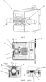
- the Fig.1 shows a perspective view of an embodiment of the receiving unit 22.
- the receiving unit 22 comprises a housing 23, which has a measuring tube holder 24.
- the measuring tube holder 24 serves to hold and guide a measuring tube.
- the measuring tube In the present receiving unit 22, the measuring tube must be inserted in a straight line in the assembly direction.
- the measuring tube holder 24 is limited by a base surface 31 in the assembly direction.
- the base surface 31 is part of the housing wall.
- the measuring tube holder 24 is limited in a direction perpendicular to the assembly direction and perpendicular to the longitudinal direction of the measuring tube 1 by two leg surfaces 46.1, 46.2.
- the leg surfaces 46.1, 46.2 can extend over several levels. Two openings are made in the leg surface 46.2, through each of which a fixing body 53 extends.
- the fixing body 53 is Part of a fixing device and designed to be spring-loaded. This means that when the measuring tube is inserted into the measuring tube holder 24, a force perpendicular to the installation direction pushes the fixing body towards the inside of the housing. When the measuring tube is in the installation position, the spring presses the fixing body into a holder provided in the measuring tube body.
- Connection contacts 28.1, 28.2, 28.3 are arranged in the leg surface 46.1 and have contact areas 29 that protrude into the measuring tube holder 24.
- the connection contacts 28.1, 28.2, 28.3 are designed to be spring-loaded and are connected to a measuring circuit. When the measuring tube is inserted, the connection contacts 28.1, 28.2, 28.3 are displaced towards the inside of the housing.
- the spring-loaded design ensures that in the final installed state of the measuring tube, the connection contacts 28.1, 28.2, 28.3 are moved towards the starting position and thus form a mechanical contact with the respective associated measuring electrode or reference electrode of the measuring tube.
- the connection between the connection contacts 28.1, 28.2, 28.3 and the respective measuring electrodes or the reference electrode is positive and/or non-positive.
- a plug connector 32 is arranged in the base surface 31 and serves to connect a temperature sensor arranged in the measuring tube with the measuring circuit arranged in particular in the housing.
- the plug connector 32 is designed to complement the contact connection of the temperature sensor.
- the contact connection of the temperature sensor is designed as a jack plug and the plug connector 32 as a jack socket.
- the Fig.2 shows a longitudinal section through an embodiment of the recording unit 22.
- the measuring circuit 30 and operating circuit 44 are arranged in the housing 23 of the recording unit 22.
- the measuring circuit 30 is set up to measure a measuring voltage at the measuring electrodes of the measuring tube. For this purpose, it is connected to connection contacts 28, which form an electrical contact with the measuring electrodes 3 when the measuring tube 1 is inserted.
- the operating circuit 44 is set up to apply a coil signal to the coil 26.
- the magnetic field generating device 25 is arranged inside the housing 23.
- the magnetic field generating device 25 comprises a coil core 27 and a coil 26, wherein the coil core 27 extends through a coil cross-section.
- the coil 26 is arranged behind the base surface 31 in the assembly direction.
- the coil core 27 has a first section which extends through the coil 26 and two sections which extend from the first section in the direction of the leg surfaces 46.1, 46.2. In the longitudinal section of the coil core, the coil core 27 takes the shape of a C or a horseshoe.
- the magnetic field generating device 25 has the shape of a magnetic field generating device 25 which is usually used in a shaded pole motor.
- the coil core 27 is preferably formed in one piece.
- the coil core 27 can be made of a solid magnetically conductive material, from a single sheet metal part or from a plurality of sheet metal parts stacked and connected to one another, in particular in the transverse direction of the coil core.
- the coil core 27 has a first coil core section 48.1, which extends through the coil 26, and a second coil core section 48.2, which extends from the first coil core section 48.1 in the direction of one of the two, in particular parallel, leg surfaces 46.1, 46.2.
- a measuring tube 1 is arranged in the measuring tube holder 24 in a mechanically detachable and in particular form-fitting and/or force-fitting manner.
- the coil core 27 is separated from the measuring tube 1 at least by the wall of the housing 23.
- the Fig.3 shows a close-up view of the longitudinal section of the Fig.2 .
- the connection contacts 28.1, 28.2 are arranged in the leg surface 46.1 and are in contact with the measuring electrodes 3.1, 3.2 via the contact areas 29.1, 29.2.
- the measuring electrodes 3.1, 3.2 each have a measuring electrode body 9 which has a first measuring electrode part 10.1 which is arranged in a first area 5.1 of the receptacle and a second measuring electrode part 10.2 which is arranged in a second area 5.2, wherein the direction of the longitudinal axes 6.1, 6.2 of the two measuring electrode parts 10.1, 10.2 differ.
- the measuring electrodes 3.1, 3.2 are each formed in two parts and arranged in a receptacle in the measuring electrode body. At least the first measuring electrode part 10.1 of the measuring electrodes 3.1, 3.2 was at least partially overmolded in an injection molding process. The second measuring electrode part 10.2 was inserted into the intended second area 5.2 of the holder after the injection molding process. The front area 11 of a first measuring electrode part 10.1 extends into the channel of the measuring tube body 2 suitable for guiding the medium. The first measuring electrode part 10.1 also has a holder 13 in the end area 12, which is designed to be complementary to a front area 14 of the second measuring electrode part 10.2.
- the front area 14 of the second measuring electrode part 10 is arranged in the holder 13 of the first measuring electrode part 10.1.
- the second measuring electrode part 10.2 has an end area 15 with a holder 16, which serves to receive a section of a connection contact 28.
- the longitudinal axis of the first measuring electrode part 10.1 corresponds to the electrode axis 21.
- the longitudinal axis of the second measuring electrode part 10.2 is aligned at an angle to the longitudinal axis of the first measuring electrode part 10.1.
- the longitudinal axis of the first measuring electrode part 10.1 and the longitudinal axis of the second measuring electrode part 10.2 form an angle of approximately 90°.
- the first measuring electrode part 10.1 and the second measuring electrode part 10.2 each have a cylindrical basic shape.
- the receptacle 14 of the first measuring electrode part 10.1 also has a cylindrical basic shape.
- the receptacle 16 of the second measuring electrode part 10.2 is designed as a convex recess and thus enables easier insertion of the connection contact 28.1, 28.2.
- the second measuring electrode part 10.2 of the first measuring electrode 3.1 is shorter than the second measuring electrode part 10.2 of the second measuring electrode 3.2. This is related to the arrangement of the connection contacts 28.1, 28.2 in the housing 23.
- the connection contact 28.2 is arranged in the entrance of the measuring tube holder 24, while the connection contact 28.1 is closer to the base surface of the measuring tube holder 24.
- the contact area 29.1 of the first connection contact 28.1 which is arranged after the second connection contact 28.2 in the assembly direction, is offset in a direction perpendicular to the assembly direction and perpendicular to the longitudinal direction of the measuring tube body or in a direction perpendicular to the longitudinal plane of the measuring tube body 2 running through the electrode axis 21. This means that the contact area 29.1 extends further into the measuring tube holder 24 than the contact area 29.2 of the second connection contact 28.2. This enables the measuring tube 1 to be inserted easily and safely into the measuring tube holder 24.
- the connection contacts 28 are designed to be spring-loaded.
- the measuring tube 1 When the measuring tube 1 is inserted, a section of the measuring tube body 2 displaces the respective contact area 29 of the connection contact 28 towards the inside of the housing.
- the spring is compressed in the process.
- the spring drives the contact area into the original position, where it is guided into the holder 16 of the second measuring electrode part 10.2 and forms a positive or at least a mechanical and electrical contact with it.
- the contact areas 29 of the connection contacts 28 are pin-shaped and rounded.
- the measuring electrode body 9 of the measuring electrodes 3.1, 3.2 is made of a material that includes metal.
- the respective measuring electrode 3.1, 3.2 takes on the shape of a pointed electrode.
- the Fig.4 shows a close-up view of a cross section of the receiving unit, in particular the measuring tube holder 24 with the measuring tube 1 inserted and a close-up view of a cross section of the receiving unit, in particular the measuring tube holder 24 without the measuring tube 1 inserted.
- the measuring tube 1 shown comprises a measuring electrode 3.1, which at least partially protrudes into the channel suitable for guiding the medium.
- a temperature sensor 17 is arranged offset in the longitudinal direction of the measuring tube 1.
- the temperature sensor 17 is suitable for determining a measured variable proportional to the medium temperature.
- a measuring circuit arranged in the housing is set up to communicate with the temperature sensor 17. Contact with the temperature sensor 17 is made via a plug connector 19, which is arranged in the base surface of the measuring tube holder 24.
- the complementary to the The connector body of the temperature sensor 17, designed as a connector 19 is plugged onto the connector 19 or inserted into the connector 19.
- a reference electrode 33 is arranged, which serves to earth the medium.
- the reference electrode 33 is designed as a pointed electrode and is connected to the measuring circuit via a third connection contact 28.3.
- the contact area 29.3 of the third connection contact 28.3 extends into a receptacle of the reference electrode 33.
- the third connection contact 28.3 is also designed to be spring-loaded.
- the first measuring electrode 3.1 or the first connection contact 28.1 is located in a first cross-sectional plane 18.1, while the reference electrode 33 is located in a second cross-sectional plane 18.2, which is arranged offset in the longitudinal direction of the measuring tube 1.
- the Fig.5 shows a longitudinal section through the design of the Fig.1 illustrated receiving unit 22, in particular by the fixing device 54 and a close-up view of the measuring tube receptacle 24.
- the illustrated fixing device 54 comprises a fixing body 53 and a spring, which is arranged on an inner surface 57 of the housing 23.
- a partial section of the fixing body 53 rests on an inner side of the housing wall, in particular on a partial section of the wall on which the leg surface 46.2 is located.
- the leg surface 46.2 there is an opening 56 through which the fixing body 53 extends.
- the fixing body 53 projects into the measuring tube receptacle 24.
- the fixing body 53 comprises a pressing surface 59, which has a plumb vector that is formed from a sum of two base vectors, namely a first base vector that points exclusively opposite to the mounting direction and a second base vector that points into the measuring tube receptacle 24 and runs perpendicular to the first base vector.
- a plug connector 19 is arranged in the base surface of the measuring tube holder 24 and is designed as a sleeve, in particular as a latch sleeve.
- the plug connector has a longitudinal axis which runs parallel to a measuring electrode axis of the measuring tube.
- the plug connector 19 is arranged offset from the coil 26 in the longitudinal direction of the measuring tube (not shown).
- the Fig.6 shows a cross-section of the Fig.1 illustrated embodiment of the receiving unit 22, in particular by the fixing device 54.
- the illustrated fixing device 54 comprises two fixing bodies 53.1 53.2, which are arranged in the housing 23 and are each designed to be resilient.
- the fixing bodies 53.1, 53.2 are arranged offset in the longitudinal direction of the measuring tube holder 24.
- the coil core 27 of the magnetic field generating device extends between the fixing bodies 53.1, 53.2.
- the fixing device 54 is arranged exclusively on one side of the measuring tube holder 24. On the opposite side are the connection contacts 28 for the Measuring electrodes and the reference electrode are attached.
- In the leg surface 46.2 there are two openings 56.1, 56.2, through which one of the fixing bodies 53.1, 53.2 extends.
- the fixing body 53 has a pressing surface 59, which ensures that a straight-line insertion of the measuring tube 1 into the measuring tube holder 24 is converted into a movement of the fixing body 53 perpendicular to the mounting direction in the direction of the housing interior upon contact between the pressing surface 59 of the fixing body 53 and the pressing surface 55 of the measuring tube 1.
- the pressing surface 59 therefore has a perpendicular vector, which is formed from a sum of two base vectors, namely a first base vector that points exclusively opposite to the mounting direction and a second base vector that points into the measuring tube holder 24 and runs perpendicular to the first base vector.
- the Fig.7 shows a perspective view of a further embodiment of the receiving unit 22 with inserted measuring tube 1.
- the Fig.7 The design shown differs from the design shown previously (see Fig. 1 to 6 ) mainly in the design of the measuring tube 1, the magnetic field generating device arranged in the housing and the measuring tube holder 24.
- the Fig.8 shows a longitudinal section through the design of the Fig.7 shown receiving unit 22, a close-up view of the measuring tube holder 24 and a close-up view of a cross section of the measuring tube holder 24, each with the measuring tube 1 inserted.
- the magnetic field generating device 25 shown essentially corresponds to the magnetic field generating device 25 from the Fig.2
- the essential difference is that two sections of the coil core 27 each extend through an opening 45.
- the coil core 27 is formed in one piece or in several parts from a solid magnetic core or from at least one single sheet metal part or from a large number of sheet metal parts stacked and connected to one another, in particular in the longitudinal direction of the pole shoe. The same applies to the pole shoe 35.
- the pole shoe 35 is not arranged in the housing 23, but on the measuring tube body 2.
- the pole shoe 35 has a base area 40 which, when installed, is in contact with the coil core 27.
- the magnetic field thus generated by the coil is guided through the coil core to the pole shoe 35 arranged on the measuring tube 1, which at least partially spans the channel of the measuring tube, whereby a substantially homogeneous magnetic field is formed inside the channel.
- the measuring tube 1 comprises two diametrically arranged pole shoes 35.1, 35.2.
- the pole shoes 35.1, 35.2 are partially encapsulated by the casting compound forming the measuring tube body 2 by means of an injection molding process, but at least to the extent that the side surfaces 38, 39 and the end surfaces 36, 37 at least are partially covered and the base surface 40 is free or partially exposed, so that there is no disadvantageous intermediate layer between the base surface 40 of the pole shoe 35 and the coil core 27.
- the base surface 40 is designed to complement the respective end section of the coil core 27. In the embodiment shown, the base surface 40 and the associated end section of the coil core 27 are designed as a flat surface.
- connection contacts corresponds to the design shown in Fig.3 .
- the Fig.9 shows a cross-section of the Fig.7 illustrated embodiment of the receiving unit 22 with inserted measuring tube 1, wherein the measuring tube 1 is inserted in the measuring tube holder 24 in a form-fitting and force-fitting manner.
- the measuring tube 1 has a receptacle 34 into which exactly one pole shoe 35 is inserted.
- the receptacle 34 is designed such that the pole shoe 35 is positively connected to the measuring tube body 2.
- the end faces 36, 37 touch the measuring tube body 2 as do the side faces 38, 39.
- the pole shoe 35 is molded around with the potting material forming the measuring tube body 2, or because the pole shoe 35 is integrated in the measuring tube body 2.
- the base area 40 of the pole shoe 35 touches the coil core 27, which extends through an opening in the end face of the measuring tube receptacle.
- the arrangements and designs of the connection contacts 28 and the fixing device 54 correspond to the previous designs shown.
- the measuring tube 1 is connected to a hose system via the process connections 60.
- the Fig.10 shows a perspective view of a design of the measuring tube 1.
- the measuring tube 1 has two diametrically arranged measuring electrodes 3.1, 3.2, each of which is designed in two parts.
- a first measuring electrode part has a first longitudinal axis 6.1, which runs perpendicular to the longitudinal axis 7 of the measuring tube 1 and corresponds to the electrode axis 21.
- the second measuring electrode part has a second longitudinal axis 6.2, which runs perpendicular to the first longitudinal axis.
- the measuring tube 1 has a temperature sensor 17 with a plug connector, which is designed to be complementary to a plug connector arranged in the receiving unit, in particular in the measuring tube receptacle.
- the plug connector of the temperature sensor 17 shown is a jack plug.
- the electrode axis 21, the reference axis 20 of the temperature sensor 17 and the longitudinal axis of the measuring tube body 7 lie in a common longitudinal plane 8.
- the measuring tube body 2 has two diametrically arranged receptacles 34 for one pole piece 35 each, whereby a reference line connecting the pole pieces 35 Longitudinal axis 7 of the measuring tube 1 intersects perpendicularly.
- the pole shoes 35 are integrated into the measuring tube body 2 in such a way that only a base surface 40 is exposed, which is brought into contact with the respective coil core arranged in the receiving unit.
- the base surface 40 is planar in the embodiment shown.
- the measuring tube 1 has two receptacles 52.1, 52.2 offset in the longitudinal direction of the measuring tube 1, which are designed to receive a fixing body of a fixing device arranged in the receptacle unit.
- a pressing surface 55 extends from the receptacles 52.1, 52.2 in the assembly direction.
- the pressing surface 55 has a perpendicular vector which is formed from the sum of two base vectors, namely a first base vector which points in the assembly direction (see arrow) and a second base vector which is oriented perpendicular to the first base vector and parallel to the second longitudinal axis 6.2.
- the pressing surface 55 serves to convert a linear assembly movement of the measuring tube 1 in the assembly direction into a linear movement of the fixing body in the direction of the housing interior.
- the pressing surface 55 displaces the fixing body evenly into the housing interior. After overcoming the pressure surface, the spring of the fixing device causes the fixing body to be moved in the direction of the holder 52.
- the holder 52 is designed to complement a section of the fixing body.
- a guide surface 32 is provided between the holder 52 and the pressure surface 55, which is designed to be inclined to the pressure surface 55 and is shaped in such a way that when a pulling force is applied to the measuring tube opposite to the assembly direction, the fixing body is guided out of the holder 52 and thus the positive and/or non-positive connection between the measuring tube 1 and the holder unit is released. According to the embodiment, an additional unlocking device is not necessary.
- a longitudinal plane of the measuring tube body which is oriented perpendicular to the electrode axis 21, divides the holders 52.1, 52.2 into two sides.
- the longitudinal plane is not a mirror plane, since only one of the two sides has a guide surface 32.
- the opposite side has a stop surface, the plumb vector of which essentially points exclusively in the assembly direction.
- the measuring tube body 2 is formed in one piece and manufactured by means of an injection molding process.
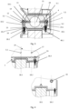
- the Fig. 11 shows a cross section through a further embodiment of the measuring tube 1 and the receiving unit 22 in the assembled state (left) and in the installed state (right). For reasons of clarity, the connection contacts have not been shown.
- a magnetic field generating device 25 is arranged in the housing 23 of the receiving unit 22, which comprises two coils 26 arranged diametrically on the measuring tube receiving unit 24, each with a coil core 27.1, 27.2. The Ends of the coil cores 27.1, 27.2 are connected to one another via exactly one field guide body 49.
- the magnetic field generating device 25 has two contact surfaces 50.1, 50.2, which extend from the front side of the housing 23 and can be contacted by field-conducting components of the measuring tube 1.
- the measuring tube 1 has two diametrically arranged measuring electrodes which are cut by an electrode axis 21. In addition, two diametrically arranged pole shoes are integrated in the measuring tube body 2.
- a longitudinal plane 41 runs perpendicular to the electrode axis 21, with the longitudinal axis of the measuring tube lying in the longitudinal plane 41.
- the longitudinal plane 41 divides the measuring tube 1 into two parts I, II.
- Part I of the measuring tube 1 has a field guide body 42 which is at least partially integrated in the measuring tube body 2 and has a first contact surface 43.1 and a second contact surface 43.2, which are each designed to be exposed and serve to form a contact with the contact surfaces 50.1, 50.2 of the magnetic field generating device 25 when the measuring tube 1 is inserted into the measuring tube holder 24.
- the field guide body 42 can be overmolded using the injection molding process, whereby the field guide body 42 is positively connected to the measuring tube body 2.
- the field guide body 42 touches the contact surfaces 50.1, 50.2 of the magnetic field generating device 25 and the generated magnetic field is guided around the measuring section of the measuring tube through the two field guide bodies 42, 49 from one coil core 27.1 to the opposite coil core 27.2.
Landscapes
- Physics & Mathematics (AREA)
- Fluid Mechanics (AREA)
- General Physics & Mathematics (AREA)
- Electromagnetism (AREA)
- Engineering & Computer Science (AREA)
- Power Engineering (AREA)
- Measuring Volume Flow (AREA)
Claims (11)
- Débitmètre magnétique comprenant- un tube de mesure interchangeable (1) pour guider un fluide dans le sens de l'écoulement, comprenant :-- un corps de tube de mesure (2),dans lequel le corps du tube de mesure (2) a un réceptacle intégré (34),dans lequel le corps du tube de mesure (2) a une surface de montage pour l'installation mécaniquement détachable du tube de mesure (1) dans une unité de réception (22) dans une position définie par la surface de montage ;-- au moins deux électrodes de mesure (3) pour former un contact galvanique avec le milieu,
dans lequel un plan longitudinal (41), dans lequel passe un axe longitudinal (7) du tube de mesure (1) et qui est perpendiculaire à un axe d'électrode (21) reliant deux électrodes de mesure (3.1, 3.2), divise le corps du tube de mesure (2) en deux côtés (I, II) ; et-- au moins une pièce polaire (35), formée d'une seule pièce de tôle ou d'une pluralité de pièces de tôle empilées et interconnectées,
dans lequel la pièce polaire (35) est disposée dans le réceptacle (34) ;- l'unité de réception (22) destinée à recevoir le tube de mesure interchangeable (1), comprenant-- un boîtier (23),
un boîtier (23), le boîtier (23) comportant un support de tube de mesure (24)-- un dispositif de génération de champ magnétique (25) pour générer un champ magnétique s'étendant à travers le réceptacle du tube de mesure (24),dans lequel le dispositif de génération de champ magnétique (25) comprend deux bobines (26.1, 26.2) ayant chacune un noyau de bobine (27.1, 27.2) s'étendant à l'intérieur d'une bobine (26.1, 26.2),dans lequel le dispositif de génération de champ magnétique (25) est disposé dans le boîtier (23) ;-- circuit de mesure (30) pour déterminer une tension de mesure appliquée aux électrodes de mesure (3) du tube de mesure (1) ;-- un circuit de commande (44) pour faire fonctionner le dispositif de génération de champ magnétique ;-- au moins deux contacts de connexion (28) conçus pour connecter les électrodes de mesure (3) du tube de mesure (1) au circuit de mesure (30) d'une manière électriquement et mécaniquement détachable,dans lequel les zones de contact (29) des contacts de connexion respectifs (28) font saillie du boîtier (23) et s'étendent dans le support du tube de mesure (24),le tube de mesure (1) est relié mécaniquement à l'unité de réception (22),caractérisé par le fait que le tube de mesure (1) comprend exactement un corps de guidage de champ (42) pour guider un champ magnétique, qui est disposé sur l'un des deux côtés (I, II) du corps du tube de mesure (2),dans lequel le corps de guidage de champ (42) est relié positivement au corps du tube de mesure (2),dans lequel le corps de guidage de champ (42) a deux surfaces de contact ouvertes (43.1, 43.2),dans lequel le dispositif de génération de champ magnétique (25) possède deux surfaces de contact (50.1, 50.2), chacune servant de surface de contact (50.1, 50.2) pour le corps de guidage de champ (42) disposé sur le tube de mesure (1),dans lequel les surfaces de contact (50.1, 50.2) sont disposées sur une face d'extrémité du boîtier (23),dans lequel le corps de guidage de champ (42) est conçu pour connecter l'un à l'autre les deux noyaux de bobine (27.1, 27.2) du dispositif de génération de champ magnétique (25) après que le tube de mesure (1) a été placé dans l'unité de réception (22). - Débitmètre magnétique selon la revendication 1,
dans lequel une pièce polaire (35) disposée sur le tube de mesure (1) et un noyau de bobine (27) s'étendant à travers une ouverture (45) dans le support du tube de mesure (24) sont en contact. - Débitmètre magnétique selon l'une quelconque des revendications précédentes,dans lequel la pièce polaire (35) présente une première face d'extrémité (36) et une seconde face d'extrémité (37), qui délimitent la pièce polaire (35) dans la direction longitudinale,dans lequel le corps du tube de mesure (2) s'étend le long de la première face d'extrémité (36) et de la deuxième face d'extrémité (37) et, en particulier, les recouvre complètement dans la direction longitudinale.
- Débitmètre magnétique selon l'une quelconque des revendications précédentes,dans lequel la pièce polaire (35) présente une première face latérale (38) et une seconde face latérale (39),dans laquelle la première face latérale (38) relie la première surface d'extrémité (36) à la deuxième surface d'extrémité (37),la seconde face latérale (39) relie la première face d'extrémité (36) à la seconde face d'extrémité (37),le corps du tube de mesure (2) s'étend le long de la première surface latérale (39) et de la deuxième surface latérale (39) et, en particulier, les recouvre entièrement.
- Débitmètre magnétique selon l'une quelconque des revendications précédentes,dans lequel une surface de base (40) de la pièce polaire (35) n'est pas ou seulement partiellement recouverte par le corps du tube de mesure (2),dans lequel la surface de base (40) relie la première surface d'extrémité (36) et la deuxième surface d'extrémité (37),dans lequel la surface de base (40) relie la première surface latérale (38) à la deuxième surface latérale (39).
- Débitmètre magnétique selon l'une quelconque des revendications précédentes,dans lequel le corps du tube de mesure (2) est monolithique,dans lequel le corps du tube de mesure (2) est formé au moyen d'un procédé de moulage primaire, en particulier au moyen d'un procédé de moulage par injection,dans lequel la pièce polaire (35) est partiellement encapsulée dans un matériau d'enrobage formant le corps du tube de mesure (2) au moyen du processus de moulage primaire, en particulier au moyen du processus de moulage par injection.
- Débitmètre magnétique selon l'une des revendications précédentes,dans lequel le noyau de la bobine (27) s'étend à travers une ouverture (45) dans le corps du tube de mesure (24),dans lequel le noyau de la bobine (27) est conçu et disposé dans l'arrangement du tube de mesure (24) de telle sorte que lorsque le tube de mesure (1) est disposé dans le support du tube de mesure (24), un contact est établi entre le noyau de la bobine (27) et la pièce polaire (35).
- Débitmètre magnétique selon l'une quelconque des revendications précédentes,dans lequel l'arrangement du tube de mesure (24) est délimité par deux surfaces de jambe (46.1, 46.2) dans une direction perpendiculaire à une direction de montage du tube de mesure (1) et perpendiculaire à la direction longitudinale du corps du tube de mesure (1),dans lequel l'agencement du tube de mesure (24) est limité par une surface de base dans la direction de montage du tube de mesure (1).
- Débitmètre magnétique selon l'une quelconque des revendications précédentes,dans lequel la bobine (26) est disposée derrière la surface de base dans le boîtier (23) dans la direction de montage,dans lequel le noyau de la bobine (27) comprend une première partie du noyau de la bobine (48.1) s'étendant à travers la bobine (26),le noyau de la bobine (27) comporte une deuxième section du noyau de la bobine (48.2) qui s'étend à partir de la première section du noyau de la bobine (48.1) en direction de l'une des deux surfaces des jambes (46.1, 46.2).
- Débitmètre magnétique selon l'une quelconque des revendications précédentes,
dans lequel le corps du tube de mesure (2) est électriquement isolant. - Débitmètre magnétique selon l'une des revendications précédentes,
dans lequel le tube de mesure (1) est relié positivement et/ou non positivement à l'unité de réception (22).
Applications Claiming Priority (2)
| Application Number | Priority Date | Filing Date | Title |
|---|---|---|---|
| DE102019135011.5A DE102019135011A1 (de) | 2019-12-18 | 2019-12-18 | Messrohr, Aufnahmeeinheit und magnetisch-induktives Durchflussmessgerät |
| PCT/EP2020/084078 WO2021121957A1 (fr) | 2019-12-18 | 2020-12-01 | Tube de mesure, unité de réception et débitmètre à induction magnétique |
Publications (2)
| Publication Number | Publication Date |
|---|---|
| EP4078099A1 EP4078099A1 (fr) | 2022-10-26 |
| EP4078099B1 true EP4078099B1 (fr) | 2024-09-11 |
Family
ID=73695007
Family Applications (1)
| Application Number | Title | Priority Date | Filing Date |
|---|---|---|---|
| EP20817283.3A Active EP4078099B1 (fr) | 2019-12-18 | 2020-12-01 | Débitmètre à induction magnétique |
Country Status (5)
| Country | Link |
|---|---|
| US (1) | US12339146B2 (fr) |
| EP (1) | EP4078099B1 (fr) |
| CN (1) | CN114787588B (fr) |
| DE (1) | DE102019135011A1 (fr) |
| WO (1) | WO2021121957A1 (fr) |
Families Citing this family (2)
| Publication number | Priority date | Publication date | Assignee | Title |
|---|---|---|---|---|
| DE102022121407A1 (de) * | 2022-08-24 | 2024-02-29 | Krohne Messtechnik Gmbh | Testvorrichtung für ein modulares magnetisch-induktives Durchflussmessgerät, Testverfahren für eine solche Testvorrichtung, Testvorrichtung für ein monolithisches magnetisch-induktives Durchflussmessgerät und Testverfahren für eine solche Testvorrichtung |
| DE102024115741A1 (de) * | 2024-06-05 | 2025-12-11 | Endress+Hauser Flowtec Ag | Meßrohr-Modul, Modul-System sowie damit gebildetes Meßgerät bzw. damit gebildete Prüfanordnung |
Family Cites Families (11)
| Publication number | Priority date | Publication date | Assignee | Title |
|---|---|---|---|---|
| DE3545155C2 (de) | 1984-12-26 | 1994-03-10 | Toshiba Kawasaki Kk | Elektromagnetisches Durchflußmeßgerät |
| US4881413A (en) | 1988-10-31 | 1989-11-21 | Bio-Medicus, Inc. | Blood flow detection device |
| JP3410818B2 (ja) * | 1994-06-20 | 2003-05-26 | 愛知時計電機株式会社 | 電磁流量計と流管部 |
| DE19535998A1 (de) * | 1995-09-27 | 1997-04-03 | Ketelsen Broder | Induktiver Durchflußmesser |
| DE19535997C2 (de) * | 1995-09-27 | 1997-09-25 | Ketelsen Broder | Induktiver Durchflußmesser |
| US20060216829A1 (en) * | 2003-03-21 | 2006-09-28 | Denis Bouboulis | Erythrocyte sedimentation rate (ESR) test measurement instrument of unitary design and method of using the same |
| US8006569B2 (en) | 2009-06-12 | 2011-08-30 | Sensus Usa Inc. | Magnetic flow meter |
| DE102012016408B4 (de) | 2012-08-21 | 2022-06-09 | Krohne Ag | Magnetisch-induktives Durchflussmessgerät mit einer Mehrzahl von Funktionseinheiten, konstruktive Realisierung |
| DE102015116679A1 (de) | 2015-01-14 | 2016-07-14 | Krohne Ag | Magnetisch-induktives Durchflussmessgerät |
| DE102016118064B4 (de) * | 2016-09-25 | 2021-12-09 | Krohne Ag | Messrohr zum Einsetzen in eine Messrohraufnahme eines magnetisch-induktiven Durchflussmessgeräts und magnetisch-induktives Durchflussmessgerät |
| JP2022530982A (ja) * | 2019-05-03 | 2022-07-05 | カムストルプ アクティーゼルスカブ | 流量計のための流管とハウジング |
-
2019
- 2019-12-18 DE DE102019135011.5A patent/DE102019135011A1/de not_active Ceased
-
2020
- 2020-12-01 US US17/757,438 patent/US12339146B2/en active Active
- 2020-12-01 CN CN202080083868.6A patent/CN114787588B/zh active Active
- 2020-12-01 EP EP20817283.3A patent/EP4078099B1/fr active Active
- 2020-12-01 WO PCT/EP2020/084078 patent/WO2021121957A1/fr not_active Ceased
Also Published As
| Publication number | Publication date |
|---|---|
| EP4078099A1 (fr) | 2022-10-26 |
| WO2021121957A1 (fr) | 2021-06-24 |
| CN114787588B (zh) | 2026-01-30 |
| CN114787588A (zh) | 2022-07-22 |
| DE102019135011A1 (de) | 2021-06-24 |
| US12339146B2 (en) | 2025-06-24 |
| US20230013776A1 (en) | 2023-01-19 |
Similar Documents
| Publication | Publication Date | Title |
|---|---|---|
| EP3301409B1 (fr) | Tube de mesure à inserer dans un logement de tube de mesure d'un débitmètre électromagnétique et débitmètre magnéto-inductif | |
| DE102007004826B4 (de) | Messvorrichtung für ein magnetisch induktives Durchflussmessgerät und Durchflussmessgerät | |
| EP0852702B1 (fr) | Debitmetre inductif | |
| DE102011079352A1 (de) | Magnetisch-induktives Durchflussmessgerät | |
| WO2013010715A1 (fr) | Débitmètre magnéto-inductif | |
| EP3433897B1 (fr) | Couvercle de boîtier, capteur de batterie et procédé de fabrication d'un capteur de batterie | |
| EP2098838B1 (fr) | Appareil de mesure de niveau de remplissage | |
| DE202005001549U1 (de) | Magnetisch-induktives Durchflussmessgerät | |
| DE102019133461A1 (de) | Magnetisch-induktives Durchflussmessgerät | |
| EP1756531B1 (fr) | Capteur de debit a induction magnetique | |
| WO2014037354A1 (fr) | Transducteur ultrasonore et procédé de fabrication d'un transducteur ultrasonore | |
| WO2021121957A1 (fr) | Tube de mesure, unité de réception et débitmètre à induction magnétique | |
| EP2761256B1 (fr) | Système à bobine pour un appareil de mesure à induction magnétique | |
| EP3648943A1 (fr) | Procédé pour la fabrication d'un débitmètre à induction magnétique et débitmètre à induction magnétique | |
| DE102019135017B3 (de) | Messrohr, Aufnahmeeinheit und magnetisch-induktives Durchflussmessgerät | |
| EP4034845B1 (fr) | Débitmètre magnéto-inductif | |
| DE102011009062A1 (de) | Magnetkreisvorrichtung für ein magnetisch-induktives Durchflussmessgerät | |
| WO2008107053A1 (fr) | Débitmètre à tourbillons pour enregistrer la vitesse d'écoulement dans une conduite | |
| DE102014113409A1 (de) | Magnetisch-induktives Durchflussmessgerät mit einem Magnetsystem mit mindestens vier Spulen | |
| DE102004063020B4 (de) | Magnetisch-induktives Durchflußmeßgerät | |
| EP0852704B1 (fr) | Debitmetre inductif | |
| DE102019135013A1 (de) | Messrohr, Aufnahmeeinheit und magnetisch-induktives Durchflussmessgerät | |
| EP4449062A1 (fr) | Débitmètre magnéto-inductif | |
| DE3628564C1 (en) | Intermediate housing with contact plate | |
| DE102020116004B3 (de) | Magnetisch-induktive Durchflussmesssonde |
Legal Events
| Date | Code | Title | Description |
|---|---|---|---|
| STAA | Information on the status of an ep patent application or granted ep patent |
Free format text: STATUS: UNKNOWN |
|
| STAA | Information on the status of an ep patent application or granted ep patent |
Free format text: STATUS: THE INTERNATIONAL PUBLICATION HAS BEEN MADE |
|
| PUAI | Public reference made under article 153(3) epc to a published international application that has entered the european phase |
Free format text: ORIGINAL CODE: 0009012 |
|
| STAA | Information on the status of an ep patent application or granted ep patent |
Free format text: STATUS: REQUEST FOR EXAMINATION WAS MADE |
|
| 17P | Request for examination filed |
Effective date: 20220518 |
|
| AK | Designated contracting states |
Kind code of ref document: A1 Designated state(s): AL AT BE BG CH CY CZ DE DK EE ES FI FR GB GR HR HU IE IS IT LI LT LU LV MC MK MT NL NO PL PT RO RS SE SI SK SM TR |
|
| DAV | Request for validation of the european patent (deleted) | ||
| DAX | Request for extension of the european patent (deleted) | ||
| GRAP | Despatch of communication of intention to grant a patent |
Free format text: ORIGINAL CODE: EPIDOSNIGR1 |
|
| STAA | Information on the status of an ep patent application or granted ep patent |
Free format text: STATUS: GRANT OF PATENT IS INTENDED |
|
| INTG | Intention to grant announced |
Effective date: 20240613 |
|
| GRAS | Grant fee paid |
Free format text: ORIGINAL CODE: EPIDOSNIGR3 |
|
| GRAA | (expected) grant |
Free format text: ORIGINAL CODE: 0009210 |
|
| STAA | Information on the status of an ep patent application or granted ep patent |
Free format text: STATUS: THE PATENT HAS BEEN GRANTED |
|
| AK | Designated contracting states |
Kind code of ref document: B1 Designated state(s): AL AT BE BG CH CY CZ DE DK EE ES FI FR GB GR HR HU IE IS IT LI LT LU LV MC MK MT NL NO PL PT RO RS SE SI SK SM TR |
|
| REG | Reference to a national code |
Ref country code: GB Ref legal event code: FG4D Free format text: NOT ENGLISH |
|
| REG | Reference to a national code |
Ref country code: CH Ref legal event code: EP |
|
| REG | Reference to a national code |
Ref country code: DE Ref legal event code: R096 Ref document number: 502020009226 Country of ref document: DE |
|
| P01 | Opt-out of the competence of the unified patent court (upc) registered |
Free format text: CASE NUMBER: APP_49077/2024 Effective date: 20240828 |
|
| RAP4 | Party data changed (patent owner data changed or rights of a patent transferred) |
Owner name: ENDRESS+HAUSER FLOWTEC AG |
|
| REG | Reference to a national code |
Ref country code: IE Ref legal event code: FG4D Free format text: LANGUAGE OF EP DOCUMENT: GERMAN |
|
| REG | Reference to a national code |
Ref country code: NL Ref legal event code: FP |
|
| REG | Reference to a national code |
Ref country code: LT Ref legal event code: MG9D |
|
| PG25 | Lapsed in a contracting state [announced via postgrant information from national office to epo] |
Ref country code: NO Free format text: LAPSE BECAUSE OF FAILURE TO SUBMIT A TRANSLATION OF THE DESCRIPTION OR TO PAY THE FEE WITHIN THE PRESCRIBED TIME-LIMIT Effective date: 20241211 |
|
| PG25 | Lapsed in a contracting state [announced via postgrant information from national office to epo] |
Ref country code: GR Free format text: LAPSE BECAUSE OF FAILURE TO SUBMIT A TRANSLATION OF THE DESCRIPTION OR TO PAY THE FEE WITHIN THE PRESCRIBED TIME-LIMIT Effective date: 20241212 Ref country code: FI Free format text: LAPSE BECAUSE OF FAILURE TO SUBMIT A TRANSLATION OF THE DESCRIPTION OR TO PAY THE FEE WITHIN THE PRESCRIBED TIME-LIMIT Effective date: 20240911 |
|
| PG25 | Lapsed in a contracting state [announced via postgrant information from national office to epo] |
Ref country code: BG Free format text: LAPSE BECAUSE OF FAILURE TO SUBMIT A TRANSLATION OF THE DESCRIPTION OR TO PAY THE FEE WITHIN THE PRESCRIBED TIME-LIMIT Effective date: 20240911 |
|
| PG25 | Lapsed in a contracting state [announced via postgrant information from national office to epo] |
Ref country code: LV Free format text: LAPSE BECAUSE OF FAILURE TO SUBMIT A TRANSLATION OF THE DESCRIPTION OR TO PAY THE FEE WITHIN THE PRESCRIBED TIME-LIMIT Effective date: 20240911 |
|
| PG25 | Lapsed in a contracting state [announced via postgrant information from national office to epo] |
Ref country code: HR Free format text: LAPSE BECAUSE OF FAILURE TO SUBMIT A TRANSLATION OF THE DESCRIPTION OR TO PAY THE FEE WITHIN THE PRESCRIBED TIME-LIMIT Effective date: 20240911 |
|
| PG25 | Lapsed in a contracting state [announced via postgrant information from national office to epo] |
Ref country code: ES Free format text: LAPSE BECAUSE OF FAILURE TO SUBMIT A TRANSLATION OF THE DESCRIPTION OR TO PAY THE FEE WITHIN THE PRESCRIBED TIME-LIMIT Effective date: 20240911 Ref country code: RS Free format text: LAPSE BECAUSE OF FAILURE TO SUBMIT A TRANSLATION OF THE DESCRIPTION OR TO PAY THE FEE WITHIN THE PRESCRIBED TIME-LIMIT Effective date: 20241211 |
|
| PG25 | Lapsed in a contracting state [announced via postgrant information from national office to epo] |
Ref country code: RS Free format text: LAPSE BECAUSE OF FAILURE TO SUBMIT A TRANSLATION OF THE DESCRIPTION OR TO PAY THE FEE WITHIN THE PRESCRIBED TIME-LIMIT Effective date: 20241211 Ref country code: NO Free format text: LAPSE BECAUSE OF FAILURE TO SUBMIT A TRANSLATION OF THE DESCRIPTION OR TO PAY THE FEE WITHIN THE PRESCRIBED TIME-LIMIT Effective date: 20241211 Ref country code: LV Free format text: LAPSE BECAUSE OF FAILURE TO SUBMIT A TRANSLATION OF THE DESCRIPTION OR TO PAY THE FEE WITHIN THE PRESCRIBED TIME-LIMIT Effective date: 20240911 Ref country code: HR Free format text: LAPSE BECAUSE OF FAILURE TO SUBMIT A TRANSLATION OF THE DESCRIPTION OR TO PAY THE FEE WITHIN THE PRESCRIBED TIME-LIMIT Effective date: 20240911 Ref country code: GR Free format text: LAPSE BECAUSE OF FAILURE TO SUBMIT A TRANSLATION OF THE DESCRIPTION OR TO PAY THE FEE WITHIN THE PRESCRIBED TIME-LIMIT Effective date: 20241212 Ref country code: FI Free format text: LAPSE BECAUSE OF FAILURE TO SUBMIT A TRANSLATION OF THE DESCRIPTION OR TO PAY THE FEE WITHIN THE PRESCRIBED TIME-LIMIT Effective date: 20240911 Ref country code: ES Free format text: LAPSE BECAUSE OF FAILURE TO SUBMIT A TRANSLATION OF THE DESCRIPTION OR TO PAY THE FEE WITHIN THE PRESCRIBED TIME-LIMIT Effective date: 20240911 Ref country code: BG Free format text: LAPSE BECAUSE OF FAILURE TO SUBMIT A TRANSLATION OF THE DESCRIPTION OR TO PAY THE FEE WITHIN THE PRESCRIBED TIME-LIMIT Effective date: 20240911 |
|
| PG25 | Lapsed in a contracting state [announced via postgrant information from national office to epo] |
Ref country code: IS Free format text: LAPSE BECAUSE OF FAILURE TO SUBMIT A TRANSLATION OF THE DESCRIPTION OR TO PAY THE FEE WITHIN THE PRESCRIBED TIME-LIMIT Effective date: 20250111 Ref country code: PT Free format text: LAPSE BECAUSE OF FAILURE TO SUBMIT A TRANSLATION OF THE DESCRIPTION OR TO PAY THE FEE WITHIN THE PRESCRIBED TIME-LIMIT Effective date: 20250113 |
|
| PG25 | Lapsed in a contracting state [announced via postgrant information from national office to epo] |
Ref country code: SM Free format text: LAPSE BECAUSE OF FAILURE TO SUBMIT A TRANSLATION OF THE DESCRIPTION OR TO PAY THE FEE WITHIN THE PRESCRIBED TIME-LIMIT Effective date: 20240911 Ref country code: RO Free format text: LAPSE BECAUSE OF FAILURE TO SUBMIT A TRANSLATION OF THE DESCRIPTION OR TO PAY THE FEE WITHIN THE PRESCRIBED TIME-LIMIT Effective date: 20240911 |
|
| PG25 | Lapsed in a contracting state [announced via postgrant information from national office to epo] |
Ref country code: EE Free format text: LAPSE BECAUSE OF FAILURE TO SUBMIT A TRANSLATION OF THE DESCRIPTION OR TO PAY THE FEE WITHIN THE PRESCRIBED TIME-LIMIT Effective date: 20240911 |
|
| PG25 | Lapsed in a contracting state [announced via postgrant information from national office to epo] |
Ref country code: PL Free format text: LAPSE BECAUSE OF FAILURE TO SUBMIT A TRANSLATION OF THE DESCRIPTION OR TO PAY THE FEE WITHIN THE PRESCRIBED TIME-LIMIT Effective date: 20240911 |
|
| PG25 | Lapsed in a contracting state [announced via postgrant information from national office to epo] |
Ref country code: SK Free format text: LAPSE BECAUSE OF FAILURE TO SUBMIT A TRANSLATION OF THE DESCRIPTION OR TO PAY THE FEE WITHIN THE PRESCRIBED TIME-LIMIT Effective date: 20240911 |
|
| REG | Reference to a national code |
Ref country code: DE Ref legal event code: R097 Ref document number: 502020009226 Country of ref document: DE |
|
| PG25 | Lapsed in a contracting state [announced via postgrant information from national office to epo] |
Ref country code: MC Free format text: LAPSE BECAUSE OF FAILURE TO SUBMIT A TRANSLATION OF THE DESCRIPTION OR TO PAY THE FEE WITHIN THE PRESCRIBED TIME-LIMIT Effective date: 20240911 |
|
| PG25 | Lapsed in a contracting state [announced via postgrant information from national office to epo] |
Ref country code: DK Free format text: LAPSE BECAUSE OF FAILURE TO SUBMIT A TRANSLATION OF THE DESCRIPTION OR TO PAY THE FEE WITHIN THE PRESCRIBED TIME-LIMIT Effective date: 20240911 |
|
| PLBE | No opposition filed within time limit |
Free format text: ORIGINAL CODE: 0009261 |
|
| STAA | Information on the status of an ep patent application or granted ep patent |
Free format text: STATUS: NO OPPOSITION FILED WITHIN TIME LIMIT |
|
| REG | Reference to a national code |
Ref country code: CH Ref legal event code: PL |
|
| PG25 | Lapsed in a contracting state [announced via postgrant information from national office to epo] |
Ref country code: LU Free format text: LAPSE BECAUSE OF NON-PAYMENT OF DUE FEES Effective date: 20241201 |
|
| 26N | No opposition filed |
Effective date: 20250612 |
|
| PG25 | Lapsed in a contracting state [announced via postgrant information from national office to epo] |
Ref country code: SE Free format text: LAPSE BECAUSE OF FAILURE TO SUBMIT A TRANSLATION OF THE DESCRIPTION OR TO PAY THE FEE WITHIN THE PRESCRIBED TIME-LIMIT Effective date: 20240911 |
|
| REG | Reference to a national code |
Ref country code: BE Ref legal event code: MM Effective date: 20241231 |
|
| PG25 | Lapsed in a contracting state [announced via postgrant information from national office to epo] |
Ref country code: BE Free format text: LAPSE BECAUSE OF NON-PAYMENT OF DUE FEES Effective date: 20241231 |
|
| PG25 | Lapsed in a contracting state [announced via postgrant information from national office to epo] |
Ref country code: CH Free format text: LAPSE BECAUSE OF NON-PAYMENT OF DUE FEES Effective date: 20241231 |
|
| PG25 | Lapsed in a contracting state [announced via postgrant information from national office to epo] |
Ref country code: IE Free format text: LAPSE BECAUSE OF NON-PAYMENT OF DUE FEES Effective date: 20241201 |
|
| PGFP | Annual fee paid to national office [announced via postgrant information from national office to epo] |
Ref country code: DE Payment date: 20251211 Year of fee payment: 6 |
|
| PGFP | Annual fee paid to national office [announced via postgrant information from national office to epo] |
Ref country code: GB Payment date: 20251219 Year of fee payment: 6 |
|
| PGFP | Annual fee paid to national office [announced via postgrant information from national office to epo] |
Ref country code: AT Payment date: 20260113 Year of fee payment: 5 |
|
| PGFP | Annual fee paid to national office [announced via postgrant information from national office to epo] |
Ref country code: IT Payment date: 20251223 Year of fee payment: 6 |
|
| PGFP | Annual fee paid to national office [announced via postgrant information from national office to epo] |
Ref country code: NL Payment date: 20251219 Year of fee payment: 6 Ref country code: FR Payment date: 20251229 Year of fee payment: 6 |
|
| PGFP | Annual fee paid to national office [announced via postgrant information from national office to epo] |
Ref country code: CZ Payment date: 20251125 Year of fee payment: 6 |
|
| PG25 | Lapsed in a contracting state [announced via postgrant information from national office to epo] |
Ref country code: CY Free format text: LAPSE BECAUSE OF FAILURE TO SUBMIT A TRANSLATION OF THE DESCRIPTION OR TO PAY THE FEE WITHIN THE PRESCRIBED TIME-LIMIT; INVALID AB INITIO Effective date: 20201201 |