EP4078704B1 - Refroidissement d'une pile à combustible - Google Patents
Refroidissement d'une pile à combustible Download PDFInfo
- Publication number
- EP4078704B1 EP4078704B1 EP21708153.8A EP21708153A EP4078704B1 EP 4078704 B1 EP4078704 B1 EP 4078704B1 EP 21708153 A EP21708153 A EP 21708153A EP 4078704 B1 EP4078704 B1 EP 4078704B1
- Authority
- EP
- European Patent Office
- Prior art keywords
- flow
- plate
- plate element
- elevations
- bipolar plate
- Prior art date
- Legal status (The legal status is an assumption and is not a legal conclusion. Google has not performed a legal analysis and makes no representation as to the accuracy of the status listed.)
- Active
Links
Images


Classifications
-
- H—ELECTRICITY
- H01—ELECTRIC ELEMENTS
- H01M—PROCESSES OR MEANS, e.g. BATTERIES, FOR THE DIRECT CONVERSION OF CHEMICAL ENERGY INTO ELECTRICAL ENERGY
- H01M8/00—Fuel cells; Manufacture thereof
- H01M8/02—Details
- H01M8/0202—Collectors; Separators, e.g. bipolar separators; Interconnectors
- H01M8/0258—Collectors; Separators, e.g. bipolar separators; Interconnectors characterised by the configuration of channels, e.g. by the flow field of the reactant or coolant
-
- H—ELECTRICITY
- H01—ELECTRIC ELEMENTS
- H01M—PROCESSES OR MEANS, e.g. BATTERIES, FOR THE DIRECT CONVERSION OF CHEMICAL ENERGY INTO ELECTRICAL ENERGY
- H01M8/00—Fuel cells; Manufacture thereof
- H01M8/02—Details
- H01M8/0202—Collectors; Separators, e.g. bipolar separators; Interconnectors
- H01M8/0267—Collectors; Separators, e.g. bipolar separators; Interconnectors having heating or cooling means, e.g. heaters or coolant flow channels
-
- H—ELECTRICITY
- H01—ELECTRIC ELEMENTS
- H01M—PROCESSES OR MEANS, e.g. BATTERIES, FOR THE DIRECT CONVERSION OF CHEMICAL ENERGY INTO ELECTRICAL ENERGY
- H01M8/00—Fuel cells; Manufacture thereof
- H01M8/02—Details
- H01M8/0297—Arrangements for joining electrodes, reservoir layers, heat exchange units or bipolar separators to each other
-
- H—ELECTRICITY
- H01—ELECTRIC ELEMENTS
- H01M—PROCESSES OR MEANS, e.g. BATTERIES, FOR THE DIRECT CONVERSION OF CHEMICAL ENERGY INTO ELECTRICAL ENERGY
- H01M8/00—Fuel cells; Manufacture thereof
- H01M8/04—Auxiliary arrangements, e.g. for control of pressure or for circulation of fluids
- H01M8/04007—Auxiliary arrangements, e.g. for control of pressure or for circulation of fluids related to heat exchange
- H01M8/04029—Heat exchange using liquids
-
- H—ELECTRICITY
- H01—ELECTRIC ELEMENTS
- H01M—PROCESSES OR MEANS, e.g. BATTERIES, FOR THE DIRECT CONVERSION OF CHEMICAL ENERGY INTO ELECTRICAL ENERGY
- H01M8/00—Fuel cells; Manufacture thereof
- H01M8/10—Fuel cells with solid electrolytes
- H01M2008/1095—Fuel cells with polymeric electrolytes
-
- H—ELECTRICITY
- H01—ELECTRIC ELEMENTS
- H01M—PROCESSES OR MEANS, e.g. BATTERIES, FOR THE DIRECT CONVERSION OF CHEMICAL ENERGY INTO ELECTRICAL ENERGY
- H01M8/00—Fuel cells; Manufacture thereof
- H01M8/02—Details
- H01M8/0202—Collectors; Separators, e.g. bipolar separators; Interconnectors
- H01M8/0258—Collectors; Separators, e.g. bipolar separators; Interconnectors characterised by the configuration of channels, e.g. by the flow field of the reactant or coolant
- H01M8/026—Collectors; Separators, e.g. bipolar separators; Interconnectors characterised by the configuration of channels, e.g. by the flow field of the reactant or coolant characterised by grooves, e.g. their pitch or depth
-
- Y—GENERAL TAGGING OF NEW TECHNOLOGICAL DEVELOPMENTS; GENERAL TAGGING OF CROSS-SECTIONAL TECHNOLOGIES SPANNING OVER SEVERAL SECTIONS OF THE IPC; TECHNICAL SUBJECTS COVERED BY FORMER USPC CROSS-REFERENCE ART COLLECTIONS [XRACs] AND DIGESTS
- Y02—TECHNOLOGIES OR APPLICATIONS FOR MITIGATION OR ADAPTATION AGAINST CLIMATE CHANGE
- Y02E—REDUCTION OF GREENHOUSE GAS [GHG] EMISSIONS, RELATED TO ENERGY GENERATION, TRANSMISSION OR DISTRIBUTION
- Y02E60/00—Enabling technologies; Technologies with a potential or indirect contribution to GHG emissions mitigation
- Y02E60/30—Hydrogen technology
- Y02E60/50—Fuel cells
Definitions
- the invention relates to a bipolar plate for cooling an electrochemical cell, and to an electrochemical cell, in particular a fuel cell, with such a bipolar plate.
- Electrochemical cells are well known. In a galvanic electrochemical cell, chemical energy is converted into electrical energy, in reversal of electrolysis.
- a known device for such a galvanic cell is the fuel cell, in which the chemical energy carrier is not stored in the cell, but is continuously made available from outside, which means that continuous operation is in principle possible.
- a well-known type of fuel cell is the low-temperature fuel cell based on polymer electrolyte membrane (PEM) technology, whose main areas of application are primarily in the mobile sector without using waste heat, for example in submarines.
- PEM polymer electrolyte membrane
- the essential element of a PEM single cell is a membrane electrode unit. This consists of two electrodes (an anode and a cathode) and an electrolyte membrane located between the two electrodes. Between the electrodes and the electrolyte membrane there is a catalyst layer in which the important physical and electrochemical processes, such as adsorption of hydrogen and oxygen on the catalyst, release and absorption of electrons and the formation of water on the cathode side by combination of protons diffused through the membrane and ( reduced) oxygen.
- the important physical and electrochemical processes such as adsorption of hydrogen and oxygen on the catalyst, release and absorption of electrons and the formation of water on the cathode side by combination of protons diffused through the membrane and ( reduced) oxygen.
- the electrodes are located on the side facing away from the electrolyte membrane or catalyst layer Side via a gas diffusion layer in contact with a so-called bipolar plate.
- This component has the task of separating the individual fuel cells (on the media side), ensuring current flow in the cell stack and removing the reaction heat.
- the bipolar plates are made of an electrically conductive material, which must have a low contact resistance to the electrodes.
- these bipolar plates consist of two plate elements, which are often provided with a milled gas channel structure, and cooling water flows through them during operation.
- bipolar plate An example of a bipolar plate can be found in the DE 10 2014 206 336 A1 .
- the bipolar plate disclosed there comprises two plates arranged together, each of which has a periodic structure with recesses in cross section, with recesses in the recesses of both plates being arranged facing away from one another to form a coolant flow area.
- the recesses are formed exclusively in a distributor structure of the bipolar plate that is arranged in the main flow direction before and/or after a flow field and partially overlap, so that a coolant flow area that allows longitudinal and transverse flow is provided.
- bipolar plate is from the US 2007/0015019 A1 and from the WO 2004/107486 A1 known.
- the separator or bipolar plate comprises two profiled plate elements that touch each other on contact surfaces, between which a fluid or flow space for the coolant is formed.
- the plate elements have several embossments arranged on the surface of the plate elements in the manner of round elevations facing away from one another with recesses facing one another.
- the embossings of both plate elements are offset relative to one another, so that the centers of the studs are one Plate element lies above a triangle center point of the other plate element, so that flow paths for the cooling water between the plates are opened, in which the water can flow from the nub of the lower plate element into the nub of the upper plate element.
- the object of the invention is to provide a bipolar plate for an electrochemical cell which enables improved cooling and which is at the same time as simple and inexpensive to produce as possible.
- a further object of the invention is to provide an electrochemical cell with such a bipolar plate.
- the invention is based on the knowledge that in the areas of temperature peaks the cooling water flow is lower than in better cooled areas and that this non-uniformity is caused by the flow resistance being isotropic evenly over the surface. This means that the edge and corner areas in particular receive less flow than the central area of the cooling field.
- the invention solves the problem directed at a bipolar plate by providing that in such a bipolar plate for an electrochemical cell, comprising a flow space arranged between a first plate element and a second plate element with a flow inlet and a flow outlet for a coolant flowing through the flow space, wherein each plate element has a contact level for contacting the other plate element and between the flow inlet and the flow outlet a plurality of elevations protruding from the contact plane and facing away from the other plate element, which have openings towards the contact plane, and wherein first flow channels are formed through the openings of the elevations in that the elevations of both plate elements are offset from one another , wherein each elevation at least partially overlaps at least one elevation of the other plate element, a direction-dependent flow resistance is set in the first flow channels of the bipolar plate by arranging the elevations on the plate elements in the corners of regular triangles and the plate elements are arranged offset from one another, so that in a projection onto the contact plane, an elevation of the first plate element is arranged off-center
- the cooling water can be e.g. B. preferably direct in the width, i.e. transversely to the direct line between flow inlet and flow outlet, in particular into the corners of the bipolar plate, and only then direct into the length of the cell.
- the streamline pattern is also expanded and the cooling water can be directed into the corner areas better than in the case of a homogeneous flow resistance distribution.
- the exact setting of the flow field and thus the temperature field can be influenced by the amount of displacement.
- elevations have frusto-conical profiles with regard to the production of the plate elements but also with regard to the flow behavior of the cooling medium in the first flow channels.
- the elevations on the plate elements are arranged in the corners of regular triangles and the plate elements are arranged offset from one another, so that in a projection onto the contact plane, an elevation of the first plate element is arranged off-center within a triangle of elevations of the second plate element.
- the streamline pattern is also expanded and the cooling water can be directed into the corner areas better than in the case of a homogeneous flow resistance distribution.
- the exact setting of the flow field and thus the temperature field can be influenced by the amount of displacement.
- a main axis of a plate element which is defined by two adjacent elevations of a plate element, is oriented perpendicular to the connecting line, with one elevation of the first plate element being displaced from a centered position relative to the next three elevations of the second plate element parallel to the connecting line is so that its distance from the next elevation of the second plate element in a direction parallel to the connecting line is greater than from the other two next elevations of the second plate element.
- the cooling medium flow is preferably set perpendicular to the direct connecting line between the flow inlet and flow outlet.
- At least two elevations of a plate element are combined to form a second flow channel.
- the passage areas between the two plate elements become larger and the flow resistance becomes smaller.
- the second flow channels are arranged at least in edge regions of the bipolar plate without a flow inlet or flow outlet. It is particularly advantageous if the second flow channels form an annular channel running around the edges of the bipolar plate, i.e. in the edge regions.
- a separating web is formed between two adjacent second flow channels of a plate element, the distance of which from the contact plane is different from zero. If necessary, a height of the separator can be zero, i.e. there is no longer a separator 16 between two adjacent second flow channels. By appropriately choosing the web height, the flow resistance and thus the volume flow can be adjusted to the desired extent.
- an orientation of a second flow channel of the first plate element is different from the orientation of a second flow channel of the second plate element.
- the task directed at an electrochemical cell is solved by an electrochemical cell comprising at least one bipolar plate according to the invention.
- the offset of the elevations only influences the cooling water space; the gas space of the cells, which is located outside the flow space for the cooling water, is not influenced.
- a bipolar plate 1 for a fuel cell is shown in a schematic top view.
- a flow space 4 for coolant K for example cooling water, is formed within the bipolar plate 1. Cooling water is introduced into the flow space 4 through a flow inlet 5 and led out through a flow outlet 6 arranged on an opposite side. The flow inlet 5 and the flow outlet 6 lie on a diagonal line, not shown here.
- the flow space 4 is delimited on its two flat sides by two plate elements 2, 3 of which in Figure 1 only a first plate element 2 is visible.
- the plate elements 2, 3 are metallic.
- the surfaces of the plate elements 2, 3 also have a profiling, which is in Figure 1 is not shown.
- the structure and arrangement of the plate elements 2, 3 according to the prior art is in the Figures 2 , 3 and 4 shown.
- a large number of knob-shaped elevations 8 are embossed into the plate elements 2, 3.
- the elevations 8 of the first plate element 2 are drawn with a continuous line, while the elevations 8 of the second plate element 3 are marked with a dashed line.
- FIG 2 A main flow direction 17 is also shown, which is essentially represented by the connecting line 11 between the flow inlet 5 and the flow outlet 6.
- FIG 3 shows a somewhat more detailed top view of two plate elements 2, 3 positioned one above the other of a bipolar plate 1 according to the prior art.
- the basic hydraulic elements of the cooling water space of the bipolar plate 1 are shown.
- a possible path of the cooling water flow in the bipolar plate 1 is shown as an example with a cutting line 12.
- the side view of the section along section line 12 is in Figure 4 shown and best describes how the cooling water path results.
- the elevations 8 of one of the plate elements 2, 3 face away from the other plate element 2, 3.
- the surveys 8 according to FIG 2 , FIG 3 and FIG 4 all have a circular cross section and are the same size and symmetrically arranged.
- Each of the plate elements 2, 3 has a contact plane 7 with which it rests on the other plate element 2, 3 and from which the elevations 8 protrude outwards. The contact between the two plate elements 2, 3 takes place in the contact level 7.
- the elevations 8 or knobs embossed in the material of the plate elements 2, 3 have an opening 9 towards the contact plane 7.
- the elevations 8 are offset from one another.
- Such an arrangement results in contact areas 18 (see Figure 3 ), where the plate elements 2, 3 touch and therefore no cooling water can flow.
- areas 19 also form in which the elevations 8 partially overlap.
- cooling water can flow from one side of the contact plane 7 to the other, so that a large number of discrete first flow channels 10 for the cooling water K run through the elevations 8 in the flow space 4.
- Figure 3 shows a part of a first flow channel 10, the course of which also follows the cutting line 12.
- a first flow channel 10 is indicated by the curved arrows.
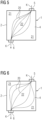
- Figure 5 shows the streamlines 20 of the cooling water in the bipolar plate 1 according to the prior art in a highly simplified schematic representation. Corner areas 21 receive a comparatively small amount of flow, while the central area 22 receives a comparatively strong amount of flow. This results in an uneven temperature distribution in the bipolar plate 1. Because of the low cooling water flow in the corner areas 21, higher temperatures arise there during operation than in the central area 22.
- Figure 6 shows the streamlines 20 of the cooling water in the bipolar plate 1 according to the invention.
- the corner areas 21 have a greater flow of cooling water through them, while the central area 22 has a correspondingly weaker flow. This can result in a homogeneous temperature distribution right down to the corner areas.
- FIGs 7 and 8 show, so to speak, a hydraulic basic element of the flow space 4 of a bipolar plate 1.
- Figure 7 shows the prior art, in which the center 14 of an elevation 8 of the first plate element 2 lies above a triangle center 15 of the second plate element 3 and in which there is no flow resistance for a cooling medium depends on the direction, which means that the cooling medium seeks the shortest path from the flow inlet 5 to the flow outlet 6 and this essentially extends along the connecting line 11 (see Figure 2 ).
- the corner areas 21 are flowed through less by the cooling medium than the middle area 22 (see Figure 5 ).
- This flow behavior changes when the plate elements 2, 3 are displaced relative to one another in such a way that the center 14 of an elevation 8 of the first plate element 2 is no longer above a triangle center 15 of the second plate element 3, but is shifted approximately in the direction of the flow inlet 5, which results in passage areas of different sizes for different directions in the flow space 4.
- Figure 8 is a main axis 24 of a plate element 2, 3, which is defined by two adjacent elevations 8 of a plate element 2, 3, oriented perpendicular to the connecting line 11, with an elevation 8 of the first plate element 2 from a centered position relative to the next three elevations 8 of the second plate element 3 is shifted parallel to the connecting line 11, so that its distance to the next elevation 8 of the second plate element 3 is greater in a direction parallel to the connecting line 11 than to the other two next elevations 8 of the second plate element 3.
- FIGS 9 and 10 show an exemplary embodiment of an edge region 23 of the plate elements 2, 3 that has been modified compared to the prior art
- Figure 9 schematically a horizontal section through a part of the first plate element 2, ie a section parallel to the plane of the first plate element 2.
- Figure 10 shows a corresponding section for the second plate element 3.
- Figure 9 also shows a vertical section through the first plate element 2 in the edge region 23.
- the section runs transversely to elevations 8, which are combined in the edge region 23 to form second flow channels 13.
- the second flow channels 13 are separated by a separating web 16.
- a height of the Separating web 16, i.e. the difference between the height of the elevations 8 and the distance of the separating web 16 from the contact plane 7, can be freely selected and thus also the flow resistance in the edge region 23.
- h With h becomes in Figure 9 denotes the distance of the separating web 16 from the contact level 7.
- the height of the elevations 8 is marked H.
- a comparatively small h means a comparatively large flow resistance in the edge region 23, at least between the second flow channels 13, a comparatively large h, ie the web is almost eliminated, therefore means a comparatively small resistance between the second channels 13 in the edge region 23.
- h corresponds the height H of the elevations 8 above the contact level 7.
- annular channel 25 running around the edge regions 23 can be formed.
- a ring channel 25 is in the Figure 11 indicated.
- the representation in the Figure 11 is very schematic and different from the Figure 6 just by this feature.
- the ring channel 25 does not necessarily have to, as in the Figure 11 shown, have a constant width along the entire flow path. Deviations are possible; it may be desirable for the flow resistance to be particularly low, particularly in the corners.
Landscapes
- Life Sciences & Earth Sciences (AREA)
- Engineering & Computer Science (AREA)
- Manufacturing & Machinery (AREA)
- Sustainable Development (AREA)
- Sustainable Energy (AREA)
- Chemical & Material Sciences (AREA)
- Chemical Kinetics & Catalysis (AREA)
- Electrochemistry (AREA)
- General Chemical & Material Sciences (AREA)
- Fuel Cell (AREA)
Claims (11)
- Plaque (1) bipolaire d'une pile électrochimique, comprenant un espace (4) d'écoulement disposé entre un premier élément (2) de la plaque et un deuxième élément (3) de la plaque et ayant une entrée (5) d'écoulement ainsi qu'une sortie (6) d'écoulement d'un fluide (K) de refroidissement passant dans l'espace (4) d'écoulement, dans laquelle chaque élément (2, 3) de la plaque a un plan (7) de contact pour la mise en contact avec respectivement l'autre élément (2, 3) de la plaque ainsi que entre l'entrée (5) d'écoulement et la sortie (6) d'écoulement, une pluralité de surélévations (8) en saillie du plan (7) et non tournées vers respectivement l'autre élément (2, 3) de la plaque, qui ont des ouvertures (9) vers le plan (7) de contact, et dans lequel des premiers conduits (10) d'écoulement sont formés par les ouvertures (9) des surélévations (8), par le fait que les deux surélévations (8) des deux éléments (2, 3) de la plaque sont décalées les unes par rapport aux autres, dans laquelle chaque surélévation (8) chevauche au moins en partie au moins une surélévation (8) de respectivement l'autre élément (2, 3) de la plaque, caractérisée en ce qu'il est établi une résistance à l'écoulement en fonction du sens dans les premiers conduits (10) d'écoulement de la plaque (1) bipolaire, par le fait que les surélévations (8) sont disposées sur les éléments (2, 3) de la plaque aux sommets de triangles équilatéraux et que les éléments (2, 3) de la plaque sont disposés en étant décalés l'un par rapport à l'autre, de manière à ce que, dans une projection sur le plan (7) de contact, une surélévation (8) du premier élément (2) de la plaque soit disposée en dehors du centre d'un triangle constitué de surélévations (8) du deuxième élément (3) de la plaque.
- Plaque (1) bipolaire suivant la revendication 1, dans laquelle la résistance à l'écoulement est plus grande dans la direction d'une ligne (11) de liaison entre l'entrée (5) et la sortie (6) d'écoulement que perpendiculairement à celle-ci.
- Plaque (1) bipolaire suivant l'une des revendications 1 ou 2, dans laquelle les surélévations (8) ont des profils en tronc de cône.
- Plaque (1) bipolaire suivant l'une des revendications précédentes, dans laquelle un axe (24) principal d'un élément (2, 3) de la plaque, qui est défini par deux surélévations (8) voisines d'un élément (2, 3) de la plaque est orienté perpendiculairement à la ligne (11) de liaison, dans laquelle une surélévation (8) du premier élément (2) de la plaque est décalée, parallèlement à la ligne (11) de liaison, d'une position centrée par rapport aux trois surélévations (8) les plus proches du deuxième élément (3) de la plaque, de manière à ce que sa distance à la surélévation (8) de la plus proche du deuxième élément (3) de la plaque soit plus grande dans une direction parallèlement à la ligne (11) de liaison que sa distance aux deux autres surélévations (8) les plus proches du deuxième élément (3) de la plaque.
- Plaque (1) bipolaire suivant l'une des revendications précédentes, dans laquelle au moins deux surélévations (8) d'un élément (2, 3) de la plaque sont rassemblées en un deuxième conduit (13) d'écoulement.
- Plaque (1) bipolaire suivant la revendication 5, dans laquelle les deuxièmes conduits (13) d'écoulement sont disposés au moins dans des parties (23) de bord de la plaque (1) bipolaire sans entrée (5) d'écoulement ou sortie (6) d'écoulement.
- Plaque (1) bipolaire suivant la revendication 6, dans laquelle les deuxièmes conduits (13) d'écoulement forment un conduit (25) annulaire faisant le tour des parties (23) de bords.
- Plaque (1) bipolaire suivant l'une des revendications 5 à 7, dans laquelle il est formé, entre deux deuxièmes conduits (13) d'écoulement voisins d'un élément (2, 3) de la plaque, une entretoise (16) de séparation, dont la distance au plan (7) de contact est différente de zéro.
- Plaque (1) bipolaire suivant la revendication 8, dans laquelle une hauteur de l'entretoise (16) de séparation est nulle.
- Plaque (1) bipolaire suivant l'une des revendications 5 à 9, dans laquelle une orientation d'un deuxième conduit (13) d'écoulement du premier élément (2) de la plaque est différente de l'orientation d'un deuxième conduit (13) d'écoulement du deuxième élément (3) de la plaque.
- Pile électrochimique, comprenant au moins une plaque (1) bipolaire suivant l'une des revendications précédentes.
Applications Claiming Priority (2)
| Application Number | Priority Date | Filing Date | Title |
|---|---|---|---|
| DE102020205871.7A DE102020205871A1 (de) | 2020-05-11 | 2020-05-11 | Brennstoffzellenkühlung |
| PCT/EP2021/053978 WO2021228445A1 (fr) | 2020-05-11 | 2021-02-18 | Refroidissement de pile à combustible |
Publications (2)
| Publication Number | Publication Date |
|---|---|
| EP4078704A1 EP4078704A1 (fr) | 2022-10-26 |
| EP4078704B1 true EP4078704B1 (fr) | 2023-11-08 |
Family
ID=74758754
Family Applications (1)
| Application Number | Title | Priority Date | Filing Date |
|---|---|---|---|
| EP21708153.8A Active EP4078704B1 (fr) | 2020-05-11 | 2021-02-18 | Refroidissement d'une pile à combustible |
Country Status (7)
| Country | Link |
|---|---|
| US (1) | US12463226B2 (fr) |
| EP (1) | EP4078704B1 (fr) |
| KR (1) | KR102931553B1 (fr) |
| DE (1) | DE102020205871A1 (fr) |
| ES (1) | ES2972093T3 (fr) |
| IL (1) | IL298012B2 (fr) |
| WO (1) | WO2021228445A1 (fr) |
Family Cites Families (8)
| Publication number | Priority date | Publication date | Assignee | Title |
|---|---|---|---|---|
| KR100669689B1 (ko) * | 2003-03-25 | 2007-01-18 | 삼성에스디아이 주식회사 | 바이폴라판과 이를 채용하는 연료전지 |
| DE10323882A1 (de) * | 2003-05-26 | 2004-12-23 | Siemens Ag | Brennstoffzelle und Heizeinrichtung einer Brennstoffzelle |
| US7419739B2 (en) * | 2004-08-25 | 2008-09-02 | General Motors Corporation | Flexible bipolar plate |
| ATE517446T1 (de) | 2005-02-03 | 2011-08-15 | Siemens Ag | Brennstoffzelle |
| EP2639868A1 (fr) | 2012-03-13 | 2013-09-18 | Siemens Aktiengesellschaft | Plaque bipolaire ainsi que cellule électrochimique dotée d'une telle plaque bipolaire |
| DE102014206336A1 (de) * | 2014-04-02 | 2015-10-08 | Volkswagen Ag | Bipolarplatte, Brennstoffzelle und ein Kraftfahrzeug |
| FR3049392B1 (fr) * | 2016-03-24 | 2018-04-20 | Commissariat A L'energie Atomique Et Aux Energies Alternatives | Plaque bipolaire de cellule electrochimique a tenue mecanique amelioree |
| CA3147747A1 (fr) * | 2019-07-16 | 2021-01-21 | Ch Innovations Inc. | Modules et ensembles de piles a combustible compacts |
-
2020
- 2020-05-11 DE DE102020205871.7A patent/DE102020205871A1/de not_active Withdrawn
-
2021
- 2021-02-18 EP EP21708153.8A patent/EP4078704B1/fr active Active
- 2021-02-18 ES ES21708153T patent/ES2972093T3/es active Active
- 2021-02-18 IL IL298012A patent/IL298012B2/en unknown
- 2021-02-18 KR KR1020227042937A patent/KR102931553B1/ko active Active
- 2021-02-18 US US17/910,816 patent/US12463226B2/en active Active
- 2021-02-18 WO PCT/EP2021/053978 patent/WO2021228445A1/fr not_active Ceased
Also Published As
| Publication number | Publication date |
|---|---|
| KR20230007500A (ko) | 2023-01-12 |
| US12463226B2 (en) | 2025-11-04 |
| IL298012B1 (en) | 2025-12-01 |
| IL298012B2 (en) | 2026-04-01 |
| IL298012A (en) | 2023-01-01 |
| US20230124648A1 (en) | 2023-04-20 |
| ES2972093T3 (es) | 2024-06-11 |
| KR102931553B1 (ko) | 2026-02-27 |
| WO2021228445A1 (fr) | 2021-11-18 |
| EP4078704A1 (fr) | 2022-10-26 |
| DE102020205871A1 (de) | 2021-11-11 |
Similar Documents
| Publication | Publication Date | Title |
|---|---|---|
| DE69908811T2 (de) | Bipolarplatten-entwurf aus metallblechen für polymerelektrolytmembran-brennstoffzellen | |
| DE112008002991B4 (de) | Brennstoffzelle und Gasseparataor für Brennstoffzelle | |
| WO2023062081A2 (fr) | Cadre pour cellules électrolytiques à pem et empilement de cellules électrolytiques à pem pour la production d'hydrogène haute pression par électrolyse à pression différentielle | |
| WO2015150536A1 (fr) | Plaque bipolaire et pile à combustible comprenant une plaque bipolaire de ce type | |
| WO2023062088A2 (fr) | Cadre pour cellules électrochimiques et dispositifs de type à empilement | |
| EP2898115B1 (fr) | Bloc d'électrolyse ainsi que cadre de cellule, module d'électrodes et kit de construction | |
| WO2022253384A1 (fr) | Plaque bipolaire et procédé pour faire fonctionner un système de pile à combustible | |
| EP4388603A1 (fr) | Plaque bipolaire et procédé pour produire une plaque bipolaire | |
| DE102008033209A1 (de) | Brennstoffzellenanordnung | |
| DE102022112931A1 (de) | Bipolarplatte und Verfahren zum Betrieb eines Brennstoffzellensystems | |
| DE102005042498A1 (de) | Mit Noppen versehene Kanalstruktur für eine bipolare Platte zur Verbesserung des Wassermanagements insbesondere auf der Kathodenseite einer Brennstoffzelle | |
| DE10226388A1 (de) | Separator für Brennstoffzelle | |
| EP4078704B1 (fr) | Refroidissement d'une pile à combustible | |
| DE102022129159B3 (de) | Bipolarplatte, Zellenstapel und Verfahren zur Herstellung einer Bipolarplatte | |
| DE102006056468A1 (de) | Bipolarplatte, insbesondere für einen Brennstoffzellenstapel eines Fahrzeugs | |
| DE102022116193B3 (de) | Bipolarplatte und Verfahren zur Herstellung einer Bipolarplatte | |
| WO2022111924A1 (fr) | Plaque bipolaire pour cellule électrochimique, agencement de cellules électrochimiques et procédé d'utilisation d'un agencement de cellules électrochimiques | |
| DE10331406A1 (de) | Vorrichtung mit Mitteln zur Führung von Fluiden und Verfahren zum Betreiben einer solchen Vorrichtung | |
| DE112004002652B4 (de) | Strömungsfeld für eine Brennstoffzelle mit Strömungspfaden mit hohem Druckgradient und Verfahren zur Herstellung einer Separatorplatte | |
| DE102022124987A1 (de) | Wasserelektrolyseseparator und elektrochemische vorrichtung | |
| DE102021214824A1 (de) | Medienverteilerstruktur, Bipolarplatte und elektrochemische Zelle | |
| DE102024111490A1 (de) | Bipolarplatte, Plattenanordnung und Elektrolyseur | |
| DE102024123593A1 (de) | Bipolarplatte für eine elektrochemische Vorrichtung | |
| DE102024204759A1 (de) | Dichtungsanordnung, Zellelement einer elektrochemischen Zelle, Zellenstapel mit einer Verteilerstruktur und Elektrolyseur | |
| DE102020213218A1 (de) | Brennstoffzellenstapel und elektrochemischer Reaktor |
Legal Events
| Date | Code | Title | Description |
|---|---|---|---|
| STAA | Information on the status of an ep patent application or granted ep patent |
Free format text: STATUS: UNKNOWN |
|
| STAA | Information on the status of an ep patent application or granted ep patent |
Free format text: STATUS: THE INTERNATIONAL PUBLICATION HAS BEEN MADE |
|
| PUAI | Public reference made under article 153(3) epc to a published international application that has entered the european phase |
Free format text: ORIGINAL CODE: 0009012 |
|
| STAA | Information on the status of an ep patent application or granted ep patent |
Free format text: STATUS: REQUEST FOR EXAMINATION WAS MADE |
|
| 17P | Request for examination filed |
Effective date: 20220721 |
|
| AK | Designated contracting states |
Kind code of ref document: A1 Designated state(s): AL AT BE BG CH CY CZ DE DK EE ES FI FR GB GR HR HU IE IS IT LI LT LU LV MC MK MT NL NO PL PT RO RS SE SI SK SM TR |
|
| GRAP | Despatch of communication of intention to grant a patent |
Free format text: ORIGINAL CODE: EPIDOSNIGR1 |
|
| STAA | Information on the status of an ep patent application or granted ep patent |
Free format text: STATUS: GRANT OF PATENT IS INTENDED |
|
| INTG | Intention to grant announced |
Effective date: 20230615 |
|
| DAV | Request for validation of the european patent (deleted) | ||
| DAX | Request for extension of the european patent (deleted) | ||
| GRAS | Grant fee paid |
Free format text: ORIGINAL CODE: EPIDOSNIGR3 |
|
| GRAA | (expected) grant |
Free format text: ORIGINAL CODE: 0009210 |
|
| STAA | Information on the status of an ep patent application or granted ep patent |
Free format text: STATUS: THE PATENT HAS BEEN GRANTED |
|
| AK | Designated contracting states |
Kind code of ref document: B1 Designated state(s): AL AT BE BG CH CY CZ DE DK EE ES FI FR GB GR HR HU IE IS IT LI LT LU LV MC MK MT NL NO PL PT RO RS SE SI SK SM TR |
|
| REG | Reference to a national code |
Ref country code: GB Ref legal event code: FG4D Free format text: NOT ENGLISH |
|
| REG | Reference to a national code |
Ref country code: CH Ref legal event code: EP |
|
| REG | Reference to a national code |
Ref country code: DE Ref legal event code: R096 Ref document number: 502021001922 Country of ref document: DE |
|
| REG | Reference to a national code |
Ref country code: IE Ref legal event code: FG4D Free format text: LANGUAGE OF EP DOCUMENT: GERMAN |
|
| REG | Reference to a national code |
Ref country code: SE Ref legal event code: TRGR |
|
| REG | Reference to a national code |
Ref country code: NO Ref legal event code: T2 Effective date: 20231108 Ref country code: LT Ref legal event code: MG9D |
|
| REG | Reference to a national code |
Ref country code: NL Ref legal event code: MP Effective date: 20231108 |
|
| PG25 | Lapsed in a contracting state [announced via postgrant information from national office to epo] |
Ref country code: GR Free format text: LAPSE BECAUSE OF FAILURE TO SUBMIT A TRANSLATION OF THE DESCRIPTION OR TO PAY THE FEE WITHIN THE PRESCRIBED TIME-LIMIT Effective date: 20240209 |
|
| PG25 | Lapsed in a contracting state [announced via postgrant information from national office to epo] |
Ref country code: IS Free format text: LAPSE BECAUSE OF FAILURE TO SUBMIT A TRANSLATION OF THE DESCRIPTION OR TO PAY THE FEE WITHIN THE PRESCRIBED TIME-LIMIT Effective date: 20240308 |
|
| PG25 | Lapsed in a contracting state [announced via postgrant information from national office to epo] |
Ref country code: LT Free format text: LAPSE BECAUSE OF FAILURE TO SUBMIT A TRANSLATION OF THE DESCRIPTION OR TO PAY THE FEE WITHIN THE PRESCRIBED TIME-LIMIT Effective date: 20231108 |
|
| PG25 | Lapsed in a contracting state [announced via postgrant information from national office to epo] |
Ref country code: NL Free format text: LAPSE BECAUSE OF FAILURE TO SUBMIT A TRANSLATION OF THE DESCRIPTION OR TO PAY THE FEE WITHIN THE PRESCRIBED TIME-LIMIT Effective date: 20231108 |
|
| PG25 | Lapsed in a contracting state [announced via postgrant information from national office to epo] |
Ref country code: NL Free format text: LAPSE BECAUSE OF FAILURE TO SUBMIT A TRANSLATION OF THE DESCRIPTION OR TO PAY THE FEE WITHIN THE PRESCRIBED TIME-LIMIT Effective date: 20231108 Ref country code: LT Free format text: LAPSE BECAUSE OF FAILURE TO SUBMIT A TRANSLATION OF THE DESCRIPTION OR TO PAY THE FEE WITHIN THE PRESCRIBED TIME-LIMIT Effective date: 20231108 Ref country code: IS Free format text: LAPSE BECAUSE OF FAILURE TO SUBMIT A TRANSLATION OF THE DESCRIPTION OR TO PAY THE FEE WITHIN THE PRESCRIBED TIME-LIMIT Effective date: 20240308 Ref country code: GR Free format text: LAPSE BECAUSE OF FAILURE TO SUBMIT A TRANSLATION OF THE DESCRIPTION OR TO PAY THE FEE WITHIN THE PRESCRIBED TIME-LIMIT Effective date: 20240209 Ref country code: BG Free format text: LAPSE BECAUSE OF FAILURE TO SUBMIT A TRANSLATION OF THE DESCRIPTION OR TO PAY THE FEE WITHIN THE PRESCRIBED TIME-LIMIT Effective date: 20240208 Ref country code: PT Free format text: LAPSE BECAUSE OF FAILURE TO SUBMIT A TRANSLATION OF THE DESCRIPTION OR TO PAY THE FEE WITHIN THE PRESCRIBED TIME-LIMIT Effective date: 20240308 |
|
| PG25 | Lapsed in a contracting state [announced via postgrant information from national office to epo] |
Ref country code: RS Free format text: LAPSE BECAUSE OF FAILURE TO SUBMIT A TRANSLATION OF THE DESCRIPTION OR TO PAY THE FEE WITHIN THE PRESCRIBED TIME-LIMIT Effective date: 20231108 Ref country code: PL Free format text: LAPSE BECAUSE OF FAILURE TO SUBMIT A TRANSLATION OF THE DESCRIPTION OR TO PAY THE FEE WITHIN THE PRESCRIBED TIME-LIMIT Effective date: 20231108 Ref country code: LV Free format text: LAPSE BECAUSE OF FAILURE TO SUBMIT A TRANSLATION OF THE DESCRIPTION OR TO PAY THE FEE WITHIN THE PRESCRIBED TIME-LIMIT Effective date: 20231108 Ref country code: HR Free format text: LAPSE BECAUSE OF FAILURE TO SUBMIT A TRANSLATION OF THE DESCRIPTION OR TO PAY THE FEE WITHIN THE PRESCRIBED TIME-LIMIT Effective date: 20231108 |
|
| REG | Reference to a national code |
Ref country code: ES Ref legal event code: FG2A Ref document number: 2972093 Country of ref document: ES Kind code of ref document: T3 Effective date: 20240611 |
|
| PG25 | Lapsed in a contracting state [announced via postgrant information from national office to epo] |
Ref country code: DK Free format text: LAPSE BECAUSE OF FAILURE TO SUBMIT A TRANSLATION OF THE DESCRIPTION OR TO PAY THE FEE WITHIN THE PRESCRIBED TIME-LIMIT Effective date: 20231108 |
|
| PG25 | Lapsed in a contracting state [announced via postgrant information from national office to epo] |
Ref country code: CZ Free format text: LAPSE BECAUSE OF FAILURE TO SUBMIT A TRANSLATION OF THE DESCRIPTION OR TO PAY THE FEE WITHIN THE PRESCRIBED TIME-LIMIT Effective date: 20231108 |
|
| PG25 | Lapsed in a contracting state [announced via postgrant information from national office to epo] |
Ref country code: SK Free format text: LAPSE BECAUSE OF FAILURE TO SUBMIT A TRANSLATION OF THE DESCRIPTION OR TO PAY THE FEE WITHIN THE PRESCRIBED TIME-LIMIT Effective date: 20231108 |
|
| PG25 | Lapsed in a contracting state [announced via postgrant information from national office to epo] |
Ref country code: SM Free format text: LAPSE BECAUSE OF FAILURE TO SUBMIT A TRANSLATION OF THE DESCRIPTION OR TO PAY THE FEE WITHIN THE PRESCRIBED TIME-LIMIT Effective date: 20231108 Ref country code: SK Free format text: LAPSE BECAUSE OF FAILURE TO SUBMIT A TRANSLATION OF THE DESCRIPTION OR TO PAY THE FEE WITHIN THE PRESCRIBED TIME-LIMIT Effective date: 20231108 Ref country code: RO Free format text: LAPSE BECAUSE OF FAILURE TO SUBMIT A TRANSLATION OF THE DESCRIPTION OR TO PAY THE FEE WITHIN THE PRESCRIBED TIME-LIMIT Effective date: 20231108 Ref country code: EE Free format text: LAPSE BECAUSE OF FAILURE TO SUBMIT A TRANSLATION OF THE DESCRIPTION OR TO PAY THE FEE WITHIN THE PRESCRIBED TIME-LIMIT Effective date: 20231108 Ref country code: DK Free format text: LAPSE BECAUSE OF FAILURE TO SUBMIT A TRANSLATION OF THE DESCRIPTION OR TO PAY THE FEE WITHIN THE PRESCRIBED TIME-LIMIT Effective date: 20231108 Ref country code: CZ Free format text: LAPSE BECAUSE OF FAILURE TO SUBMIT A TRANSLATION OF THE DESCRIPTION OR TO PAY THE FEE WITHIN THE PRESCRIBED TIME-LIMIT Effective date: 20231108 |
|
| REG | Reference to a national code |
Ref country code: DE Ref legal event code: R097 Ref document number: 502021001922 Country of ref document: DE |
|
| PLBE | No opposition filed within time limit |
Free format text: ORIGINAL CODE: 0009261 |
|
| STAA | Information on the status of an ep patent application or granted ep patent |
Free format text: STATUS: NO OPPOSITION FILED WITHIN TIME LIMIT |
|
| PG25 | Lapsed in a contracting state [announced via postgrant information from national office to epo] |
Ref country code: MC Free format text: LAPSE BECAUSE OF FAILURE TO SUBMIT A TRANSLATION OF THE DESCRIPTION OR TO PAY THE FEE WITHIN THE PRESCRIBED TIME-LIMIT Effective date: 20231108 |
|
| REG | Reference to a national code |
Ref country code: CH Ref legal event code: PL |
|
| PG25 | Lapsed in a contracting state [announced via postgrant information from national office to epo] |
Ref country code: LU Free format text: LAPSE BECAUSE OF NON-PAYMENT OF DUE FEES Effective date: 20240218 |
|
| 26N | No opposition filed |
Effective date: 20240809 |
|
| PG25 | Lapsed in a contracting state [announced via postgrant information from national office to epo] |
Ref country code: CH Free format text: LAPSE BECAUSE OF NON-PAYMENT OF DUE FEES Effective date: 20240229 |
|
| PG25 | Lapsed in a contracting state [announced via postgrant information from national office to epo] |
Ref country code: SI Free format text: LAPSE BECAUSE OF FAILURE TO SUBMIT A TRANSLATION OF THE DESCRIPTION OR TO PAY THE FEE WITHIN THE PRESCRIBED TIME-LIMIT Effective date: 20231108 |
|
| PG25 | Lapsed in a contracting state [announced via postgrant information from national office to epo] |
Ref country code: SI Free format text: LAPSE BECAUSE OF FAILURE TO SUBMIT A TRANSLATION OF THE DESCRIPTION OR TO PAY THE FEE WITHIN THE PRESCRIBED TIME-LIMIT Effective date: 20231108 Ref country code: LU Free format text: LAPSE BECAUSE OF NON-PAYMENT OF DUE FEES Effective date: 20240218 Ref country code: CH Free format text: LAPSE BECAUSE OF NON-PAYMENT OF DUE FEES Effective date: 20240229 |
|
| REG | Reference to a national code |
Ref country code: BE Ref legal event code: MM Effective date: 20240229 |
|
| PG25 | Lapsed in a contracting state [announced via postgrant information from national office to epo] |
Ref country code: BE Free format text: LAPSE BECAUSE OF NON-PAYMENT OF DUE FEES Effective date: 20240229 |
|
| PG25 | Lapsed in a contracting state [announced via postgrant information from national office to epo] |
Ref country code: IE Free format text: LAPSE BECAUSE OF NON-PAYMENT OF DUE FEES Effective date: 20240218 |
|
| PG25 | Lapsed in a contracting state [announced via postgrant information from national office to epo] |
Ref country code: IE Free format text: LAPSE BECAUSE OF NON-PAYMENT OF DUE FEES Effective date: 20240218 Ref country code: BE Free format text: LAPSE BECAUSE OF NON-PAYMENT OF DUE FEES Effective date: 20240229 |
|
| PGFP | Annual fee paid to national office [announced via postgrant information from national office to epo] |
Ref country code: SE Payment date: 20250224 Year of fee payment: 5 |
|
| PGFP | Annual fee paid to national office [announced via postgrant information from national office to epo] |
Ref country code: AT Payment date: 20250417 Year of fee payment: 5 |
|
| PG25 | Lapsed in a contracting state [announced via postgrant information from national office to epo] |
Ref country code: CY Free format text: LAPSE BECAUSE OF FAILURE TO SUBMIT A TRANSLATION OF THE DESCRIPTION OR TO PAY THE FEE WITHIN THE PRESCRIBED TIME-LIMIT; INVALID AB INITIO Effective date: 20210218 |
|
| PG25 | Lapsed in a contracting state [announced via postgrant information from national office to epo] |
Ref country code: HU Free format text: LAPSE BECAUSE OF FAILURE TO SUBMIT A TRANSLATION OF THE DESCRIPTION OR TO PAY THE FEE WITHIN THE PRESCRIBED TIME-LIMIT; INVALID AB INITIO Effective date: 20210218 |
|
| PG25 | Lapsed in a contracting state [announced via postgrant information from national office to epo] |
Ref country code: FI Free format text: LAPSE BECAUSE OF FAILURE TO SUBMIT A TRANSLATION OF THE DESCRIPTION OR TO PAY THE FEE WITHIN THE PRESCRIBED TIME-LIMIT Effective date: 20231108 |
|
| GBPC | Gb: european patent ceased through non-payment of renewal fee |
Effective date: 20250218 |
|
| PG25 | Lapsed in a contracting state [announced via postgrant information from national office to epo] |
Ref country code: TR Free format text: LAPSE BECAUSE OF FAILURE TO SUBMIT A TRANSLATION OF THE DESCRIPTION OR TO PAY THE FEE WITHIN THE PRESCRIBED TIME-LIMIT Effective date: 20231108 |
|
| PG25 | Lapsed in a contracting state [announced via postgrant information from national office to epo] |
Ref country code: GB Free format text: LAPSE BECAUSE OF NON-PAYMENT OF DUE FEES Effective date: 20250218 |
|
| PGFP | Annual fee paid to national office [announced via postgrant information from national office to epo] |
Ref country code: ES Payment date: 20260317 Year of fee payment: 6 |
|
| PGFP | Annual fee paid to national office [announced via postgrant information from national office to epo] |
Ref country code: NO Payment date: 20260218 Year of fee payment: 6 Ref country code: DE Payment date: 20260220 Year of fee payment: 6 |
|
| PGFP | Annual fee paid to national office [announced via postgrant information from national office to epo] |
Ref country code: IT Payment date: 20260220 Year of fee payment: 6 |
|
| PGFP | Annual fee paid to national office [announced via postgrant information from national office to epo] |
Ref country code: FR Payment date: 20260224 Year of fee payment: 6 |