EP4078819B1 - Rétroaction de probabilité d'erreur d'unité de données de protocole (pdu) - Google Patents
Rétroaction de probabilité d'erreur d'unité de données de protocole (pdu) Download PDFInfo
- Publication number
- EP4078819B1 EP4078819B1 EP19957032.6A EP19957032A EP4078819B1 EP 4078819 B1 EP4078819 B1 EP 4078819B1 EP 19957032 A EP19957032 A EP 19957032A EP 4078819 B1 EP4078819 B1 EP 4078819B1
- Authority
- EP
- European Patent Office
- Prior art keywords
- data unit
- error probability
- protocol data
- pdcp
- pdu
- Prior art date
- Legal status (The legal status is an assumption and is not a legal conclusion. Google has not performed a legal analysis and makes no representation as to the accuracy of the status listed.)
- Active
Links
Images



Classifications
-
- H—ELECTRICITY
- H03—ELECTRONIC CIRCUITRY
- H03M—CODING; DECODING; CODE CONVERSION IN GENERAL
- H03M13/00—Coding, decoding or code conversion, for error detection or error correction; Coding theory basic assumptions; Coding bounds; Error probability evaluation methods; Channel models; Simulation or testing of codes
- H03M13/01—Coding theory basic assumptions; Coding bounds; Error probability evaluation methods; Channel models; Simulation or testing of codes
-
- H—ELECTRICITY
- H03—ELECTRONIC CIRCUITRY
- H03M—CODING; DECODING; CODE CONVERSION IN GENERAL
- H03M13/00—Coding, decoding or code conversion, for error detection or error correction; Coding theory basic assumptions; Coding bounds; Error probability evaluation methods; Channel models; Simulation or testing of codes
- H03M13/37—Decoding methods or techniques, not specific to the particular type of coding provided for in groups H03M13/03 - H03M13/35
- H03M13/3738—Decoding methods or techniques, not specific to the particular type of coding provided for in groups H03M13/03 - H03M13/35 with judging correct decoding
-
- H—ELECTRICITY
- H04—ELECTRIC COMMUNICATION TECHNIQUE
- H04L—TRANSMISSION OF DIGITAL INFORMATION, e.g. TELEGRAPHIC COMMUNICATION
- H04L1/00—Arrangements for detecting or preventing errors in the information received
- H04L1/0001—Systems modifying transmission characteristics according to link quality, e.g. power backoff
- H04L1/0023—Systems modifying transmission characteristics according to link quality, e.g. power backoff characterised by the signalling
- H04L1/0026—Transmission of channel quality indication
-
- H—ELECTRICITY
- H04—ELECTRIC COMMUNICATION TECHNIQUE
- H04L—TRANSMISSION OF DIGITAL INFORMATION, e.g. TELEGRAPHIC COMMUNICATION
- H04L1/00—Arrangements for detecting or preventing errors in the information received
- H04L1/08—Arrangements for detecting or preventing errors in the information received by repeating transmission, e.g. Verdan system
-
- H—ELECTRICITY
- H04—ELECTRIC COMMUNICATION TECHNIQUE
- H04L—TRANSMISSION OF DIGITAL INFORMATION, e.g. TELEGRAPHIC COMMUNICATION
- H04L1/00—Arrangements for detecting or preventing errors in the information received
- H04L1/20—Arrangements for detecting or preventing errors in the information received using signal quality detector
-
- H—ELECTRICITY
- H03—ELECTRONIC CIRCUITRY
- H03M—CODING; DECODING; CODE CONVERSION IN GENERAL
- H03M13/00—Coding, decoding or code conversion, for error detection or error correction; Coding theory basic assumptions; Coding bounds; Error probability evaluation methods; Channel models; Simulation or testing of codes
- H03M13/03—Error detection or forward error correction by redundancy in data representation, i.e. code words containing more digits than the source words
- H03M13/05—Error detection or forward error correction by redundancy in data representation, i.e. code words containing more digits than the source words using block codes, i.e. a predetermined number of check bits joined to a predetermined number of information bits
- H03M13/09—Error detection only, e.g. using cyclic redundancy check [CRC] codes or single parity bit
-
- H—ELECTRICITY
- H04—ELECTRIC COMMUNICATION TECHNIQUE
- H04L—TRANSMISSION OF DIGITAL INFORMATION, e.g. TELEGRAPHIC COMMUNICATION
- H04L1/00—Arrangements for detecting or preventing errors in the information received
- H04L1/004—Arrangements for detecting or preventing errors in the information received by using forward error control
- H04L1/0056—Systems characterized by the type of code used
- H04L1/0061—Error detection codes
Definitions
- Some example embodiments may generally relate to mobile or wireless telecommunication systems, such as Long Term Evolution (LTE) or fifth generation (5G) radio access technology or new radio (NR) access technology, or other communications systems.
- LTE Long Term Evolution
- 5G fifth generation
- NR new radio
- certain embodiments may relate to systems and/or methods for error probability feedback.
- Examples of mobile or wireless telecommunication systems may include the Universal Mobile Telecommunications System (UMTS) Terrestrial Radio Access Network (UTRAN), Long Term Evolution (LTE) Evolved UTRAN (E-UTRAN), LTE-Advanced (LTE-A), MulteFire, LTE-A Pro, and/or fifth generation (5G) radio access technology or new radio (NR) access technology.
- UMTS Universal Mobile Telecommunications System
- UTRAN Universal Mobile Telecommunications System
- LTE Long Term Evolution
- E-UTRAN Evolved UTRAN
- LTE-A LTE-Advanced
- MulteFire LTE-A Pro
- 5G wireless systems refer to the next generation (NG) of radio systems and network architecture.
- NG next generation
- a 5G system is mostly built on a 5G new radio (NR), but a 5G (or NG) network can also build on the E-UTRA radio.
- NR provides bitrates on the order of 10-20 Gbit/s or higher, and can support at least service categories such as enhanced mobile broadband (eMBB) and ultra-reliable low-latency-communication (URLLC) as well as massive machine type communication (mMTC).
- eMBB enhanced mobile broadband
- URLLC ultra-reliable low-latency-communication
- mMTC massive machine type communication
- NR is expected to deliver extreme broadband and ultra-robust, low latency connectivity and massive networking to support the Internet of Things (IoT).
- IoT and machine-to-machine (M2M) communication With IoT and machine-to-machine (M2M) communication becoming more widespread, there will be a growing need for networks that meet the needs of lower power, low data rate, and long battery life.
- the next generation radio access network (NG-RAN) represents the RAN for 5G, which can provide both NR and LTE (and LTE-Advanced) radio accesses.
- the nodes that can provide radio access functionality to a user equipment may be named next-generation NB (gNB) when built on NR radio and may be named next-generation eNB (NG-eNB) when built on E-UTRA radio.
- gNB next-generation NB
- NG-eNB next-generation eNB
- An embodiment is directed to a method that includes transmitting, to at least one user equipment, configuration for protocol data unit error probability calculation and reporting, and receiving, from the at least one user equipment, feedback related to the protocol data unit error probability, wherein the configuration comprises at least one of: an indication of a network layer of the protocol data unit error probability calculation; and an indication of a specific channel, quality of service flow, radio bearer, and/or leg for the protocol data unit error probability calculation.
- Another embodiment is directed to an apparatus that includes means for transmitting, to at least one user equipment, configuration for protocol data unit error probability calculation and reporting, and means for receiving, from the at least one user equipment, feedback related to the protocol data unit error probability, wherein the configuration comprises at least one of: an indication of a network layer of the protocol data unit error probability calculation; and an indication of a specific channel, quality of service flow, radio bearer, and/or leg for the protocol data unit error probability calculation.
- Another embodiment is directed to a method that includes receiving, at a user equipment, a configuration from a network node, where the configuration is for protocol data unit error probability calculation and reporting, transmitting, to the network node, feedback related to the protocol data unit error probability, wherein the configuration comprises at least one of: an indication of a network layer of the protocol data unit error probability calculation; and an indication of a specific channel, quality of service flow, radio bearer, and/or leg for the protocol data unit error probability calculation.
- Another embodiment is directed to apparatus that includes means for receiving, from a network node, a configuration for protocol data unit error probability calculation and reporting for at least one network layer, means for enabling logging and estimating of block error probability, means for calculating the protocol data unit error probability for the at least one network layer based on the received configuration and the block error probability estimation, and means for transmitting, to the network node, feedback related to the protocol data unit error probability, wherein the configuration comprises at least one of: an indication of a network layer of the protocol data unit error probability calculation; and an indication of a specific channel, quality of service flow, radio bearer, and/or leg for the protocol data unit error probability calculation.
- Certain embodiments may relate to optimization and/or improvement of URLLC, for example, by introducing a new radio feedback to measure reliability of a radio link.
- URLLC is a relatively new area for wireless communication, and is considered as an important pillar in 5 th generation (5G) cellular networks (the others including enhanced mobile broadband and massive machine type of communication).
- 5G 5 th generation
- URLLC potentially opens a wide variety of new use cases for wireless networks in various vertical domains such as, but not limited to, industry automation or eHealth. Private and virtual private networks to support the vertical use cases with 5G is expected to be a promising growth area in the wireless industry.
- URLLC sets new, more stringent optimization criteria for the network deployments.
- the network should support ultra-high reliability (e.g. 99.999% or higher) and, in some cases, can also support extremely low e2e latency and jitter (e.g., guaranteed, deterministic latency of 1ms and microsecond-level jitter).
- e2e latency and jitter e.g., guaranteed, deterministic latency of 1ms and microsecond-level jitter.
- 5G URLLC use cases it should be noted that some embodiments are applicable also to other 5G use cases (e.g., eMBB and mMTC), as well as other wireless technologies (e.g., industrial Wi-Fi).
- URLLC applications typically have QoS requirements related to packet error probability; for instance, each packet arriving to a gNB should be delivered within certain delay and with certain probability, or only certain amount of consecutive packet errors are tolerated within a certain time window.
- a requirement may relate to error probability target on some radio layer such as packet data convergence protocol (PDCP).
- PDCP packet data convergence protocol
- a packet arrives to the gNB, it is passed to lower layers; at each layer, the data from may be split to one or more segments which are again passed to lower layers.
- PHY physical layer
- the bits of the packet may have been split to multiple code blocks, which are transmitted over different physical radio resource blocks, each potentially having de-correlating radio channel conditions.
- An existing method is to tune block error probability (BLEP) to a certain percentage with the help of channel quality indicator (CQI) reports, which have proven to be a reasonable method, e.g., to optimize MBB type traffic.
- BLEP block error probability
- CQI channel quality indicator
- an overriding problem relates to how to estimate performance (close to real time), on layers above physical, without extensive collection of measurements.
- Certain embodiments provide methods that are able to address and solve at least the problems discussed above.
- certain embodiments provide a new feedback mechanism for a transmitter to obtain error probability estimate of protocol data unit (PDU) at any radio layer.
- This new key performance indicator (KPI) may be referred to as PDU error probability (PDU-EP) or Lx-PDU-EP, where Lx refers to the layer where the estimate is computed (e.g., between PHY and service data adaptation protocol (SDAP)).
- a receiver may track which code blocks (CB) contributed to transmission of the Lx-PDU and may calculate the PDU-EP based on BLEP estimates of the decoded user plane CBs.
- CB code blocks
- the BLEP estimate can be computed at the receiver (e.g., UE) based on mutual information (MI) based link to system mapping, e.g., mutual information effective signal-to-noise ratio (SNR) mapping (MIESM).
- MI mutual information
- MIESM mutual information effective signal-to-noise ratio
- BLEP may be computed from successfully received user plane data (e.g., CB's that contributed to transmission of the Lx-PDU) considering the actual modulation coding scheme (MCS) and code block size and the effective signal-to-interference-and-noise ratio (SINR) after decoding.
- MCS modulation coding scheme
- SINR effective signal-to-interference-and-noise ratio
- the precise method of BLEP estimation may be left up to receiver implementation, or may be standard defined.
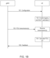
- Figs. 1A , 1B , 1C , and 1D illustrate example signaling diagrams, according to various example embodiments. It should be noted that Figs. 1A-1D are just some examples, and other examples are possible according to certain embodiments.
- Fig. 1A illustrates an example signaling diagram, according to an example embodiment. It is noted that the example of Fig. 1A depicts signaling between a first network element, network element 1, and a second network element, network element 2.
- network element 1 may represent a base station, such as a gNB or eNB, or may represent a UE. Additionally, in certain embodiments, network element 2 may represent a UE.
- Fig. 1B illustrates another example signaling diagram depicting a downlink case in which network element 1 is represented by gNB1 and network element 2 is represented by a UE.
- Fig. 1C illustrates yet another example signaling diagram depicting an uplink case in which network element 1 is represented by UE1 and network element 2 is represented by UE2.
- Fig. 1D illustrates another example signaling diagram according to a multi-connectivity scenario, according to one embodiment.
- network element 1 may transmit a configuration to network element 2 (or UE or UE2).
- the configuration may include information about PDU-EP calculation and reporting for one or more particular network layers (Lx).
- the configuration provided by network element 1 may be a measurement configuration that may include information regarding one or more layer(s) of PDU-EP calculation, one or more specific channel(s) where to compute PDU-EP, such as QoS flow, radio bearer, and/or leg (e.g., radio link control (RLC)-entity).
- the configuration may be provided by network element 1 (or gNB1 or UE1), to network element 2 (or UE or UE2), over radio resource control (RRC).
- RRC radio resource control
- logging and estimation of BLEP may be enabled at network element 2.
- network element 2 may enable BLEP estimation for user-plane CBs and log the BLEP values.
- network element 2 may log how the received CBs map to upper layers PDU's at the network layer(s), Lx.
- network element 2 may receive one or more PDU transmissions.
- network element 2 may calculate PDU-EP for the network layer(s), Lx.
- the calculating of the PDU-EP may include, when network element 2 (or UE or UE2) decodes a user plane PDU matching to the received configuration, using the logged BLEP values and the CB to PDU mapping to calculate the PDU-EP for the network layer(s), Lx, based on the CBs that contributed to the transmission of the PDU.
- network element 2 (or UE or UE2) may report feedback related to the PDU-EP to network element 1 (or gNB1 or UE1).
- network element 2 may report feedback periodically, for example, based on a fixed time interval or received number of PDUs for the specific layer(s), Lx.
- network element 2 may report feedback aperiodically, for example, based on triggers (e.g., upon the occurrence or detection of such triggers), such as a medium access control (MAC)-control element (CE).
- triggers e.g., upon the occurrence or detection of such triggers
- CE medium access control
- network element 2 or UE or UE2 may utilize event-based reporting, such as triggering the feedback reporting based on certain thresholds. Further, in some embodiments, the reporting of feedback may be dynamically switched on or off.
- the feedback reporting may include one or more of PDU-EP statistics and/or additional information associated with the PDU-EP statistics.
- PDU-EP statistics may include a single PDU-EP value, statistical value of several PDU-EPs (e.g., mean, percentile, and/or standard), and/or an event indicating that PDU-EP is below or above threshold.
- the additional information associated with the PDU-EP statistics may include an identifier (ID) of the PDU, such as PDCP sequence number (SN), a channel (e.g., RLC-leg, QoS flow, radio bearer), number of re-transmissions, and/or time difference between reception of duplicate and primary PDCP-PDUs.
- ID identifier
- the PDU-EP value can be compressed.
- a single bit may be used to indicate if PDU-EP is above or below the threshold.
- Fig. 1D illustrates another example signaling diagram for a multi-connectivity scenario, according to an example embodiment.
- network element 1 may represent a master gNB
- network element 2 may represent a UE
- network element 3 may represent a secondary gNB.
- the signaling in the example of Fig. 1D may be similar to that of Fig. 1A , however in Fig. 1D the PDU-transmission, at 103, may be from network element 3 that is the secondary gNB and the reporting of secondary gNB PDU-EPs, at 105, may be performed directly to the master gNB.
- Fig. 2 illustrates an example of the mapping of PDUs from MAC to SDAP and including PHY layer.
- PHY-PDU-EP may be equal to the CB BLEP after hybrid automatic repeat request (HARQ)
- MAC-PDU-EP may be the error probability of transport block (TB) calculated from the CB BLEPs
- RLC-PDU-EP may be the error probability of MAC-PDU-EPs that contributed to the RLC-PDU transmission.
- PDU-EP on layer n may be computed by calculating joint-error-probability of the lower layer (N-1)-PDU-EPs (denoted by P n- 1 ).
- the joint-error-probability may be the same as the inverse probability of all (N-1) PDUs being received successfully, because if one or more (N-1)-PDUs fails, then the N-PDU fails.
- the PDCP-PDU-EP for the first two IP packets would be equal to the first MAC-PDU-EP or TB error probability.
- the PDCP-PDU would be joint-error-probability of the two MAC-PDUs that contributed to the transmission.
- Fig. 3 illustrates an example of PDCP duplication, where PDCP-PDU can be duplicated via a second leg (leg2) that can be another component carrier (CC) and/or dual connectivity (DC).
- CC component carrier
- DC dual connectivity
- certain embodiments may provide a method of collecting labelled training data for ML based PDCP duplication.
- a ML model may predict whether a PDCP-PDU be duplicated and on which leg; this prediction may be called an action.
- the ML model may be built in various ways, and example embodiments may be applicable to various implementations.
- the action and state may be associated with a reward/label measuring outcome of the action.
- state and action with a positive reward can be used to reinforce certain actions to be more probable, and correspondingly bad actions can be discouraged.
- the ML model does not necessarily use state and may associate just action and reward.
- a UE may be configured to feedback PDCP PDU-EP of both legs.
- the feedback may be associated with corresponding SN that allows the network to calculate arbitrary label for each duplication decision. This way, the ML algorithm can classify and label actions, even though all PDUs would have been received successfully, helping to steer the algorithm to meet the URLLC reliability goals.
- the feedback may be optimized by providing PDU-EP target for the receiver and to report one bit indicating if the PDU-EP was below or above the target.
- a network node such as a gNB, may configure one or more UE(s) for PDCP-PDU-EP measurement and reporting.
- the PDCP-PDU measurement may be performed per leg, which may be denoted by P primary and P secondary .
- a definition of PDCP-PDU-EP threshold, denoted by P target may be provided by the network node to the UE(s).
- the measurements may be associated with corresponding PDCP SN.
- the network node may predict duplication for each PDCP-PDU, and may temporarily store one or more of state (optional), action/duplication decision, and/or sequence number of the PDCP-PDU.
- the UE(s) may feedback PDCP-PDU-EP report(s) to the network node.
- the feedback may include a bitmap of the conditions and associated with PDCP SN.
- the feedback reporting may be without PDCP SN and the report(s) may be ordered by sequence number. Therefore, the transmitter can map the reports to corresponding SN.
- the report may include the SN to help synchronize the mapping.
- T diff can be reported that is useful with DC.
- the delay of a secondary leg may be also obtained through Xn interface, but measuring it in UE may be more efficient.
- the reporting may be performed with n-bits.
- Table 1 below illustrates an example of PDCP-PDU-EP reporting for ML based PDCP duplication.
- T diff [-3, -2, -1, 0, 1, 2, 3, 4] may be reported with 3 bits denoting the time difference in transmission time intervals (TTIs) or milliseconds.
- TTIs transmission time intervals
- T diff (optional) report 1 1 1 1 100000 001 report 2 1 0 1 100001 000 report 3 0 0 0 100010 100 1 0 0 100011 001
- the reported PDCP-PDU-EPs may be used to classify the actions.
- Fig. 4A illustrates an example table of the classification of actions based on the PDCP-PDU-EP feedback. For instance, as shown in column 6 of Fig. 4A , even though the PDCP-PDU was received correctly it can be classified as failure if the PDCP-PDU-EP was meeting the target. Respectively, in columns 1 & 2 of Fig. 4A , if the primary PDCP-PDU was received with sufficient PDCP-PDU-EP, the duplicate PDCP-PDU was obsolete and, therefore, this action can be labelled as unnecessary duplication.
- Fig. 4B illustrates a table depicting an example of classification by considering reliability and delay target, according to an example embodiment.
- a label for the action may be determined based on the classification. While the ML-model training can be done in numerous ways, in one example referring to Fig. 4A , a reward of +1 may be assigned for categories 3, 4a and 5, and -1 may be assigned otherwise. This will encourage the ML-model to just perform duplication when it is needed thereby improving spectral efficiency and decreasing the need for duplication, since less interference is generated.
- Fig. 5A illustrates an example flow diagram of a method for error probability feedback, according to one example embodiment.
- the flow diagram of Fig. 5A may be performed by a network entity or network node associated with a communication system, such as LTE or 5G NR.
- the network node performing the method of Fig. 5A may include a base station, eNB, gNB, and/or NG-RAN node.
- the network node performing the method of Fig. 5A may include a UE, mobile device, mobile station, IoT device, or the like.
- the method of Fig. 5A may be performed by network element 1 of Fig. 1A or Fig. 1D , gNB1 of Fig. 1B , and/or UE1 of Fig. 1C , as discussed above.
- the method includes at 500, transmitting, to at least one UE or network element, a configuration for PDU-EP calculation and reporting.
- the configuration includes an indication of a network layer for the PDU-EP calculation, and/or an indication of a specific channel, quality of service flow, radio bearer, and/or leg for the PDU-EP calculation.
- the configuration is transmitted to the at least one UE over RRC.
- the configuration may include a target threshold for the PDU-EP.
- the method may include transmitting one or more PDUs to the at least one UE.
- the method of Fig. 5A also includes, at 510, receiving, from the at least one UE or network element, feedback related to the PDU-EP.
- the receiving 510 may include receiving the feedback periodically based on a fixed time interval or received number of PDUs, for example.
- the receiving 510 may include receiving the feedback aperiodically based, for example, on triggers.
- the receiving 510 may include receiving the feedback based on meeting certain thresholds.
- the feedback may be dynamically switched on or off.
- the feedback may include PDU-EP statistics, such as a single PDU-EP value, a statistical value of a plurality of PDU-EPs, and/or an event indicating PDU-EP is below or above a certain threshold.
- the feedback may include additional information associated with the PDU-EP statistics, such as an identifier of the PDU, an indication of the channel where the PDU error probability was computed, an indication of a number of retransmission for the PDU, and/or an indication of a time difference between reception of a duplicate and primary PDCP PDU.
- the feedback may include a single bit indicating whether the protocol data unit error probability is above or below the target threshold.
- the example of Fig. 5A may be applicable to a PDCP duplication scenario.
- the transmitting 500 may include configuring the at least one UE for PDCP PDU-EP measurement and reporting.
- the configuring of the at least one UE for the PDCP PDU-EP measurement and reporting may include one or more of: providing instructions to perform the PDCP PDU-EP measurement per leg, providing a definition of a threshold for the PDCP PDU-EP measurement, providing instructions to compute a joint error probability for each leg, providing instructions to compute the threshold comparison for each PDCP PDU, and/or providing instructions to associate the PDCP PDU-EP measurement with a corresponding PDCP sequence number.
- the method may include predicting duplication for each PDCP PDU, and temporarily storing a prediction of whether a PDCP PDU should be duplicated, a decision on whether to duplicate the PDCP PDU, and/or a sequence number of the PDCP PDU.
- the method may also include receiving a PDCP PDU-EP report, using the PDCP PDU-EP report to classify the prediction of whether a PDCP PDU should be duplicated, and determining a label for the prediction based on the classification.
- the determined label may be used to train a ML model to perform PDCP duplication when the duplication is needed, and avoid unnecessary duplications.
- Fig. 5B illustrates an example flow diagram of a method for error probability feedback, according to one example embodiment.
- the flow diagram of Fig. 5B may be performed by a network entity or network node associated with a communications system, such as LTE or 5G NR.
- the network entity performing the method of Fig. 5B may include a UE, mobile device, mobile station, IoT device, or the like.
- the method of Fig. 5B may be performed by network element 2 of Fig. 1A or Fig. 1D , UE of Fig. 1B , and/or UE2 of Fig. 1C , as discussed above.
- the method of Fig. 5B may include, at 550, receiving, from a network node, configuration for PDU-EP calculation and reporting for at least one network layer.
- the configuration may include an indication of a network layer for the PDU-EP calculation, and/or an indication of a specific channel, quality of service flow, radio bearer, and/or leg for the PDU-EP calculation.
- the configuration may be received from the network node over RRC.
- the configuration may include a target threshold for the PDU-EP.
- the method may also include, at 560, enabling logging and estimating of BLEP.
- the enabling 560 may include enabling BLEP estimation for one or more user plane CBs and logging the BLEP values.
- the enabling 560 may also include the logging of a mapping of user plane CBs to upper layer PDUs at the at least one network layer.
- the method of Fig. 5B may include, at 570, receiving one or more PDU(s) from the network node or another network node.
- the method of Fig. 5B may include, at 580, calculating the PDU-EP for the at least one network layer based on the received configuration and the BLEP estimation.
- the calculating 580 may include, when a PDU is decoded that matches to the received configuration, using the logged BLEP values and the mapping of the user plane CBs to the upper layer PDUs to calculate the PDU-EP for the at least one network layer based on CBs that contributed to transmission of the PDU.
- the calculating 580 may include computing the PDU-EP by calculating a joint error probability of a layer immediately lower than the at least one network layer. For example, if the PDU-EP on the at least one layer is denoted as P n , the PDU-EP may be computed by calculating joint error probability of the lower layer (N-1)-PDU-EPs denoted by P n -1 .
- the method of Fig. 5B may further include, at 590, transmitting, to the network node, feedback related to the PDU-EP.
- the feedback may be transmitted periodically based on a fixed time interval or received number of PDUs, the feedback may be transmitted aperiodically based on triggers, and/or the feedback may be transmitted based on meeting certain thresholds.
- the feedback may include one or more of: a single PDU-EP value, a statistical value of a plurality of PDU-Eps, an event indicating PDU-EP is below or above a certain threshold, an identifier of the PDU, an indication of the channel where the PDU-EP was computed, an indication of a number of retransmission for the PDU, and/or an indication of a time difference between reception of a duplicate and primary PDCP PDU.
- the feedback when the configuration includes a target threshold for the PDU-EP, the feedback may include a single bit indicating whether the PDU-EP is above or below the target threshold. It is noted that, in certain embodiments, the transmission of the feedback may be dynamically switched on or off.
- the receiving 550 may include receiving a configuration for PDCP PDU-EP measurement and reporting.
- the configuration for the PDCP PDU-EP measurement and reporting may include one or more of: instructions to perform the PDCP PDU-EP measurement per leg, a definition of a threshold for the PDCP PDU-EP measurement, instructions to compute a joint error probability for each of the legs, instructions to compute the threshold comparison for each PDCP PDU, and/or instructions to associate the PDCP PDU-EP measurement with a corresponding PDCP sequence number.
- the transmitting 290 may include transmitting, to the network node, a PDCP PDU-EP report.
- apparatus 10 may be a node, host, or server in a communications network or serving such a network.
- apparatus 10 may be a satellite, base station, a Node B, an evolved Node B (eNB), 5G Node B or access point, next generation Node B (NG-NB or gNB), and/or WLAN access point, associated with a radio access network, such as a LTE network, 5G or NR.
- apparatus 10 may be NG-RAN node, an eNB in LTE, or gNB in 5G.
- apparatus 10 may be a UE, mobile device, mobile station, IoT device, or the like.
- apparatus 10 may be comprised of an edge cloud server as a distributed computing system where the server and the radio node may be stand-alone apparatuses communicating with each other via a radio path or via a wired connection, or they may be located in a same entity communicating via a wired connection.
- apparatus 10 represents a gNB
- it may be configured in a central unit (CU) and distributed unit (DU) architecture that divides the gNB functionality.
- the CU may be a logical node that includes gNB functions such as transfer of user data, mobility control, radio access network sharing, positioning, and/or session management, etc.
- the CU may control the operation of DU(s) over a front-haul interface.
- the DU may be a logical node that includes a subset of the gNB functions, depending on the functional split option. It should be noted that one of ordinary skill in the art would understand that apparatus 10 may include components or features not shown in Fig. 6A .
- apparatus 10 may include a processor 12 for processing information and executing instructions or operations.
- processor 12 may be any type of general or specific purpose processor.
- processor 12 may include one or more of general-purpose computers, special purpose computers, microprocessors, digital signal processors (DSPs), field-programmable gate arrays (FPGAs), application-specific integrated circuits (ASICs), and processors based on a multi-core processor architecture, as examples. While a single processor 12 is shown in Fig. 6A , multiple processors may be utilized according to other embodiments.
- apparatus 10 may include two or more processors that may form a multiprocessor system (e.g., in this case processor 12 may represent a multiprocessor) that may support multiprocessing.
- processor 12 may represent a multiprocessor
- the multiprocessor system may be tightly coupled or loosely coupled (e.g., to form a computer cluster).
- Processor 12 may perform functions associated with the operation of apparatus 10, which may include, for example, precoding of antenna gain/phase parameters, encoding and decoding of individual bits forming a communication message, formatting of information, and overall control of the apparatus 10, including processes related to management of communication resources.
- Apparatus 10 may further include or be coupled to a memory 14 (internal or external), which may be coupled to processor 12, for storing information and instructions that may be executed by processor 12.
- Memory 14 may be one or more memories and of any type suitable to the local application environment, and may be implemented using any suitable volatile or nonvolatile data storage technology such as a semiconductor-based memory device, a magnetic memory device and system, an optical memory device and system, fixed memory, and/or removable memory.
- memory 14 can be comprised of any combination of random access memory (RAM) 54, read only memory (ROM) 44, static storage such as a magnetic or optical disk, hard disk drive (HDD), or any other type of non-transitory machine or computer readable media.
- RAM random access memory
- ROM read only memory
- HDD hard disk drive
- apparatus 10 may include a non-volatile media 64.
- non-volatile media 64 may be a removable media.
- Memory 14 and/or media 64 may store software, computer program code or instructions.
- the instructions stored in memory 14 or media 64 may include program instructions or computer program code that, when executed by processor 12, enable the apparatus 10 to perform tasks as described herein.
- apparatus 10 may further include or be coupled to (internal or external) a drive or port that is configured to accept and read an external computer readable storage medium, such as an optical disc, USB drive, flash drive, or any other storage medium.
- an external computer readable storage medium such as an optical disc, USB drive, flash drive, or any other storage medium.
- the external computer readable storage medium may store a computer program or software for execution by processor 12 and/or apparatus 10.
- apparatus 10 may also include or be coupled to one or more antennas 15 for transmitting and receiving signals and/or data to and from apparatus 10.
- Apparatus 10 may further include or be coupled to a transceiver 18 configured to transmit and receive information.
- the transceiver 18 may include, for example, a plurality of radio interfaces that may be coupled to the antenna(s) 15.
- the radio interfaces may correspond to a plurality of radio access technologies including one or more of GSM, NB-IoT, LTE, 5G, WLAN, Bluetooth, BT-LE, NFC, radio frequency identifier (RFID), ultrawideband (UWB), MulteFire, and the like.
- the radio interface may include components, such as filters, converters (for example, digital-to-analog converters and the like), mappers, a Fast Fourier Transform (FFT) module, and the like, to generate symbols for a transmission via one or more downlinks and to receive symbols (for example, via an uplink).
- filters for example, digital-to-analog converters and the like
- mappers for example, mappers
- FFT Fast Fourier Transform
- transceiver 18 may be configured to modulate information on to a carrier waveform for transmission by the antenna(s) 15 and demodulate information received via the antenna(s) 15 for further processing by other elements of apparatus 10.
- transceiver 18 may be capable of transmitting and receiving signals or data directly.
- apparatus 10 may include an input and/or output device (I/O device).
- memory 14 may store software modules that provide functionality when executed by processor 12.
- the modules may include, for example, an operating system that provides operating system functionality for apparatus 10.
- the memory may also store one or more functional modules, such as an application or program, to provide additional functionality for apparatus 10.
- the components of apparatus 10 may be implemented in hardware, or as any suitable combination of hardware and software.
- processor 12 and memory 14 may be included in or may form a part of processing circuitry or control circuitry.
- transceiver 18 may be included in or may form a part of transceiver circuitry.
- circuitry may refer to hardware-only circuitry implementations (e.g., analog and/or digital circuitry), combinations of hardware circuits and software, combinations of analog and/or digital hardware circuits with software/firmware, any portions of hardware processor(s) with software (including digital signal processors) that work together to case an apparatus (e.g., apparatus 10) to perform various functions, and/or hardware circuit(s) and/or processor(s), or portions thereof, that use software for operation but where the software may not be present when it is not needed for operation.
- hardware-only circuitry implementations e.g., analog and/or digital circuitry
- combinations of hardware circuits and software e.g., combinations of analog and/or digital hardware circuits with software/firmware
- any portions of hardware processor(s) with software including digital signal processors
- circuitry may also cover an implementation of merely a hardware circuit or processor (or multiple processors), or portion of a hardware circuit or processor, and its accompanying software and/or firmware.
- circuitry may also cover, for example, a baseband integrated circuit in a server, cellular network node or device, or other computing or network device.
- apparatus 10 may be a network node or RAN node, such as a base station, access point, Node B, eNB, gNB, WLAN access point, or the like.
- apparatus 10 may be a UE, mobile device, mobile station, IoT device, or the like.
- apparatus 10 may be configured to perform one or more of the processes depicted in any of the flow charts or signaling diagrams described herein, such as those illustrated in Figs. 1A , 1B , 1C , 1D , 3 , 5A or 5B .
- apparatus 10 may be configured to perform a procedure relating to error probability feedback.
- apparatus 10 may be controlled by memory 14 and processor 12 to transmit, to at least one UE, a configuration for PDU-EP calculation and reporting.
- the configuration includes an indication of a network layer for the PDU-EP calculation, and/or an indication of a specific channel, quality of service flow, radio bearer, and/or leg for the PDU-EP calculation.
- the configuration may be transmitted to the at least one UE over RRC.
- the configuration may include a target threshold for the PDU-EP.
- the method may include transmitting one or more PDUs to the at least one UE.
- apparatus 10 may be controlled by memory 14 and processor 12 to receive, from the at least one UE, feedback related to the PDU-EP.
- the feedback may be received periodically based on a fixed time interval or received number of PDUs, for example.
- the feedback may be received aperiodically based, for example, on triggers.
- the feedback may be received based on meeting certain thresholds.
- the feedback may be dynamically switched on or off.
- the feedback may include PDU-EP statistics, such as a single PDU-EP value, a statistical value of a plurality of PDU-EPs, and/or an event indicating PDU-EP is below or above a certain threshold.
- the feedback may include additional information associated with the PDU-EP statistics, such as an identifier of the PDU, an indication of the channel where the PDU error probability was computed, an indication of a number of retransmission for the PDU, and/or an indication of a time difference between reception of a duplicate and primary PDCP PDU.
- the feedback may include a single bit indicating whether the protocol data unit error probability is above or below the target threshold.
- apparatus 10 may be controlled by memory 14 and processor 12 to configure the at least one UE for PDCP PDU-EP measurement and reporting.
- apparatus 10 may be controlled by memory 14 and processor 12 to configure the at least one UE for the PDCP PDU-EP measurement and reporting by one or more of: providing instructions to perform the PDCP PDU-EP measurement per leg, providing a definition of a threshold for the PDCP PDU-EP measurement, providing instructions to compute a joint error probability for each leg, providing instructions to compute the threshold comparison for each PDCP PDU, and/or providing instructions to associate the PDCP PDU-EP measurement with a corresponding PDCP sequence number.
- apparatus 10 may be controlled by memory 14 and processor 12 to predict duplication for each PDCP PDU, and temporarily store a prediction of whether a PDCP PDU should be duplicated, a decision on whether to duplicate the PDCP PDU, and/or a sequence number of the PDCP PDU.
- apparatus 10 may be controlled by memory 14 and processor 12 to receive a PDCP PDU-EP report, use the PDCP PDU-EP report to classify the prediction of whether a PDCP PDU should be duplicated, and/or determine a label for the prediction based on the classification.
- apparatus 10 may be controlled by memory 14 and processor 12 to configure utilize the determined label to train a ML model to perform PDCP duplication when the duplication is needed, and thereby avoid unnecessary duplications.
- apparatus 20 may be a node or element in a communications network or associated with such a network, such as a UE, mobile equipment (ME), mobile station, mobile device, stationary device, IoT device, or other device.
- UE may alternatively be referred to as, for example, a mobile station, mobile equipment, mobile unit, mobile device, user device, subscriber station, wireless terminal, tablet, smart phone, IoT device, sensor or NB-IoT device, or the like.
- apparatus 20 may be implemented in, for instance, a wireless handheld device, a wireless plug-in accessory, or the like.
- apparatus 20 may include one or more processors, one or more computer-readable storage medium (for example, memory, storage, or the like), one or more radio access components (for example, a modem, a transceiver, or the like), and/or a user interface.
- apparatus 20 may be configured to operate using one or more radio access technologies, such as GSM, LTE, LTE-A, NR, 5G, WLAN, WiFi, NB-IoT, Bluetooth, NFC, MulteFire, and/or any other radio access technologies. It should be noted that one of ordinary skill in the art would understand that apparatus 20 may include components or features not shown in Fig. 6B .
- apparatus 20 may include two or more processors that may form a multiprocessor system (e.g., in this case processor 22 may represent a multiprocessor) that may support multiprocessing.
- processor 22 may represent a multiprocessor
- the multiprocessor system may be tightly coupled or loosely coupled (e.g., to form a computer cluster).
- Processor 22 may perform functions associated with the operation of apparatus 20 including, as some examples, precoding of antenna gain/phase parameters, encoding and decoding of individual bits forming a communication message, formatting of information, and overall control of the apparatus 20, including processes related to management of communication resources.
- Apparatus 20 may further include or be coupled to a memory 24 (internal or external), which may be coupled to processor 22, for storing information and instructions that may be executed by processor 22.
- Memory 24 may be one or more memories and of any type suitable to the local application environment, and may be implemented using any suitable volatile or nonvolatile data storage technology such as a semiconductor-based memory device, a magnetic memory device and system, an optical memory device and system, fixed memory, and/or removable memory.
- memory 24 can be comprised of any combination of random access memory (RAM) 84, read only memory (ROM) 74, static storage such as a magnetic or optical disk, hard disk drive (HDD), or any other type of non-transitory machine or computer readable media.
- RAM random access memory
- ROM read only memory
- HDD hard disk drive
- apparatus 20 may include a non-volatile media 94.
- non-volatile media 94 may be a removable media.
- Memory 24 and/or media 94 may store software, computer program code or instructions. The instructions stored in memory 24 or media 94 may include program instructions or computer program code that, when executed by processor 22, enable the apparatus 20 to perform tasks as described herein.
- apparatus 20 may further include or be coupled to (internal or external) a drive or port that is configured to accept and read an external computer readable storage medium, such as an optical disc, USB drive, flash drive, or any other storage medium.
- an external computer readable storage medium such as an optical disc, USB drive, flash drive, or any other storage medium.
- the external computer readable storage medium may store a computer program or software for execution by processor 22 and/or apparatus 20.
- apparatus 20 may also include or be coupled to one or more antennas 25 for receiving a downlink signal and for transmitting via an uplink from apparatus 20.
- Apparatus 20 may further include a transceiver 28 configured to transmit and receive information.
- the transceiver 28 may also include a radio interface (e.g., a modem) coupled to the antenna 25.
- the radio interface may correspond to a plurality of radio access technologies including one or more of GSM, LTE, LTE-A, 5G, NR, WLAN, NB-IoT, Bluetooth, BT-LE, NFC, RFID, UWB, and the like.
- the radio interface may include other components, such as filters, converters (for example, digital-to-analog converters and the like), symbol demappers, signal shaping components, an Inverse Fast Fourier Transform (IFFT) module, and the like, to process symbols, such as OFDMA symbols, carried by a downlink or an uplink.
- filters for example, digital-to-analog converters and the like
- symbol demappers for example, digital-to-analog converters and the like
- signal shaping components for example, an Inverse Fast Fourier Transform (IFFT) module, and the like
- IFFT Inverse Fast Fourier Transform
- transceiver 28 may be configured to modulate information on to a carrier waveform for transmission by the antenna(s) 25 and demodulate information received via the antenna(s) 25 for further processing by other elements of apparatus 20.
- transceiver 28 may be capable of transmitting and receiving signals or data directly.
- apparatus 20 may include an input and/or output device (I/O device).
- apparatus 20 may further include a user interface, such as a graphical user interface or touchscreen.
- memory 24 stores software modules that provide functionality when executed by processor 22.
- the modules may include, for example, an operating system that provides operating system functionality for apparatus 20.
- the memory may also store one or more functional modules, such as an application or program, to provide additional functionality for apparatus 20.
- the components of apparatus 20 may be implemented in hardware, or as any suitable combination of hardware and software.
- apparatus 20 may optionally be configured to communicate with apparatus 10 via a wireless or wired communications link 70 according to any radio access technology, such as NR.
- processor 22 and memory 24 may be included in or may form a part of processing circuitry or control circuitry.
- transceiver 28 may be included in or may form a part of transceiving circuitry.
- apparatus 20 may be a UE, mobile device, mobile station, ME, IoT device and/or NB-IoT device, for example.
- apparatus 20 may be controlled by memory 24 and processor 22 to perform the functions associated with example embodiments described herein.
- apparatus 20 may be configured to perform one or more of the processes depicted in any of the flow charts or signaling diagrams described herein, such as those illustrated in Figs. 1A , 1B , 1C , 1D , 3 , 5A or 5B .
- apparatus 20 may include or represent a UE and may be configured to perform a procedure relating to error probability feedback, for instance.
- apparatus 20 may be controlled by memory 24 and processor 22 to receive, from a network node, configuration for PDU-EP calculation and reporting for at least one network layer.
- the configuration includes an indication of a network layer for the PDU-EP calculation, and/or an indication of a specific channel, quality of service flow, radio bearer, and/or leg for the PDU-EP calculation.
- the configuration may be received from the network node over RRC.
- the configuration may include a target threshold for the PDU-EP.
- apparatus 20 may be controlled by memory 24 and processor 22 to enable logging and estimating of BLEP.
- apparatus 20 may be controlled by memory 24 and processor 22 to enable BLEP estimation for one or more user plane CBs and log the BLEP values.
- apparatus 20 may be controlled by memory 24 and processor 22 to log a mapping of user plane CBs to upper layer PDUs at the at least one network layer.
- apparatus 20 may be controlled by memory 24 and processor 22 to receive one or more PDU(s) from the network node or another network node. According to certain embodiments, apparatus 20 may be controlled by memory 24 and processor 22 to calculate the PDU-EP for the at least one network layer based on the received configuration and the BLEP estimation. According to certain embodiments, when a PDU is decoded that matches to the received configuration, apparatus 20 may be controlled by memory 24 and processor 22 to use the logged BLEP values and the mapping of the user plane CBs to the upper layer PDUs to calculate the PDU-EP for the at least one network layer based on CBs that contributed to transmission of the PDU.
- apparatus 20 may be controlled by memory 24 and processor 22 to calculate the PDU-EP by calculating a joint error probability of a layer immediately lower than the at least one network layer. For example, if the PDU-EP on the at least one layer is denoted as P n , apparatus 20 may be controlled by memory 24 and processor 22 to compute the PDU-EP by calculating joint error probability of the lower layer (N-1)-PDU-EPs denoted by P n -1 .
- apparatus 20 may be controlled by memory 24 and processor 22 to transmit, to the network node, feedback related to the PDU-EP.
- apparatus 20 may be controlled by memory 24 and processor 22 to transmit the feedback periodically based on a fixed time interval or received number of PDUs, aperiodically based on triggers, and/or based on meeting certain thresholds.
- the feedback may include one or more of: a single PDU-EP value, a statistical value of a plurality of PDU-Eps, an event indicating PDU-EP is below or above a certain threshold, an identifier of the PDU, an indication of the channel where the PDU-EP was computed, an indication of a number of retransmission for the PDU, and/or an indication of a time difference between reception of a duplicate and primary PDCP PDU.
- the feedback when the configuration includes a target threshold for the PDU-EP, the feedback may include a single bit indicating whether the PDU-EP is above or below the target threshold. It is noted that, in certain embodiments, the transmission of the feedback may be dynamically switched on or off.
- apparatus 20 may be controlled by memory 24 and processor 22 to receive a configuration for PDCP PDU-EP measurement and reporting.
- the configuration for the PDCP PDU-EP measurement and reporting may include one or more of: instructions to perform the PDCP PDU-EP measurement per leg, a definition of a threshold for the PDCP PDU-EP measurement, instructions to compute a joint error probability for each of the legs, instructions to compute the threshold comparison for each PDCP PDU, and/or instructions to associate the PDCP PDU-EP measurement with a corresponding PDCP sequence number.
- apparatus 20 may be controlled by memory 24 and processor 22 to transmit, to the network node, a PDCP PDU-EP report.
- certain example embodiments provide several technological improvements, enhancements, and/or advantages over existing technological processes and constitute an improvement at least to the technological field of wireless network control and management.
- certain embodiments may improve URLLC, for instance, by introducing a new radio feedback to measure reliability of the radio link.
- some embodiments may provide improvements in other applications such as, but not limited to, eMBB and mMTC, as well as other wireless technologies (e.g., industrial Wi-Fi).
- eMBB and mMTC as well as other wireless technologies (e.g., industrial Wi-Fi).
- eMBB evolved mobile broadband
- mMTC wireless technology
- some example embodiments can provide improvements in spectral efficiency and may decrease the need for duplication, for example, due to the generation of less interference. Accordingly, the use of certain example embodiments results in improved functioning of communications networks and their nodes, such as base stations, eNBs, gNBs, and/or UEs or mobile stations.
- any of the methods, processes, signaling diagrams, algorithms or flow charts described herein may be implemented by software and/or computer program code or portions of code stored in memory or other computer readable or tangible media, and executed by a processor.
- an apparatus may be included or be associated with at least one software application, module, unit or entity configured as arithmetic operation(s), or as a program or portions of it (including an added or updated software routine), executed by at least one operation processor.
- Programs also called program products or computer programs, including software routines, applets and macros, may be stored in any apparatus-readable data storage medium and may include program instructions to perform particular tasks.
- a computer program product may include one or more computer-executable components which, when the program is run, are configured to carry out some example embodiments.
- the one or more computer-executable components may be at least one software code or portions of code. Modifications and configurations for implementing the functionality of an example embodiment may be performed as routine(s), which may be implemented as added or updated software routine(s). In one example, software routine(s) may be downloaded into the apparatus.
- software or computer program code or portions of code may be in source code form, object code form, or in some intermediate form, and it may be stored in some sort of carrier, distribution medium, or computer readable medium, which may be any entity or device capable of carrying the program.
- carrier may include a record medium, computer memory, read-only memory, photoelectrical and/or electrical carrier signal, telecommunications signal, and/or software distribution package, for example.
- the computer program may be executed in a single electronic digital computer or it may be distributed amongst a number of computers.
- the computer readable medium or computer readable storage medium may be a non-transitory medium.
- the functionality may be performed by hardware or circuitry included in an apparatus, for example through the use of an application specific integrated circuit (ASIC), a programmable gate array (PGA), a field programmable gate array (FPGA), or any other combination of hardware and software.
- ASIC application specific integrated circuit
- PGA programmable gate array
- FPGA field programmable gate array
- the functionality may be implemented as a signal, such as a non-tangible means, that can be carried by an electromagnetic signal downloaded from the Internet or other network.
- an apparatus such as a node, device, or a corresponding component, may be configured as circuitry, a computer or a microprocessor, such as single-chip computer element, or as a chipset, which may include at least a memory for providing storage capacity used for arithmetic operation(s) and/or an operation processor for executing the arithmetic operation(s).
Landscapes
- Engineering & Computer Science (AREA)
- Quality & Reliability (AREA)
- Physics & Mathematics (AREA)
- Probability & Statistics with Applications (AREA)
- Computer Networks & Wireless Communication (AREA)
- Signal Processing (AREA)
- Theoretical Computer Science (AREA)
- Mobile Radio Communication Systems (AREA)
- Detection And Prevention Of Errors In Transmission (AREA)
Claims (13)
- Appareil, comprenant :des moyens pour transmettre à au moins un équipement utilisateur une configuration pour un calcul et un rapport de probabilité d'erreur d'unité de données de protocole ; etdes moyens pour recevoir de l'au moins un équipement utilisateur une rétroaction liée à la probabilité d'erreur d'unité de données de protocolecaractérisé en ce que :
la configuration comprend au moins une parmi :une indication d'une couche de réseau du calcul de probabilité d'erreur d'unité de données de protocole ; etune indication d'un canal spécifique, d'un flux de qualité de service, d'un support radio, et/ou d'un segment pour le calcul de probabilité d'erreur d'unité de données de protocole. - Appareil selon la revendication 1, dans lequel l'appareil comprend en outre :
des moyens pour transmettre au moins une unité de données de protocole à l'au moins un équipement utilisateur. - Appareil selon l'une des revendications 1 et 2,dans lequel la rétroaction est reçue périodiquement sur la base d'un intervalle de temps fixe ou d'un nombre reçu d'unités de données de protocole ; oudans lequel la rétroaction est reçue périodiquement sur la base de déclencheurs ; oudans lequel la rétroaction est reçue sur la base de l'atteinte de certains seuils.
- Appareil selon l'une des revendications 1 à 3, dans lequel la rétroaction est activée ou désactivée de manière dynamique.
- Appareil selon l'une des revendications 1 à 4, dans lequel la rétroaction comprend au moins un parmi :une valeur de probabilité d'erreur d'unité de données de protocole unique ;une valeur statistique d'une pluralité de probabilités d'erreur d'unité de données de protocole ;un événement indiquant que la probabilité d'erreur d'unité de données de protocole est inférieure ou supérieure à un certain seuil ;un identifiant de l'unité de données de protocole ;une indication du canal où la probabilité d'erreur d'unité de données de protocole a été calculée ;une indication d'un nombre de retransmissions pour l'unité de données de protocole ; ouune indication d'une différence de temps entre la réception d'unités de données de protocole de protocole de convergence des données par paquets (PDCP) dupliquée et primaire.
- Appareil selon l'une des revendications 1 à 5, dans lequel la configuration comprend un seuil cible pour la probabilité d'erreur d'unité de données de protocole, et dans lequel la rétroaction comprend un bit unique indiquant si la probabilité d'erreur d'unité de données de protocole est supérieure ou inférieure au seuil cible.
- Appareil selon l'une des revendications 1 à 6, dans lequel l'appareil comprend en outre :des moyens pour configurer l'au moins un équipement utilisateur pour une mesure et un rapport de probabilité d'erreur d'unité de données de protocole de protocole de convergence des données par paquets (PDCP),dans lequel la configuration de l'au moins un équipement utilisateur comprend au moins l'une des étapes suivantes :
fournir des instructions pour effectuer la mesure de probabilité d'erreur d'unité de données de protocole de protocole de convergence des données par paquets (PDCP) par segment, fournir une définition d'un seuil pour la mesure de probabilité d'erreur d'unité de données de protocole de protocole de convergence des données par paquets (PDCP), fournir des instructions pour calculer une probabilité d'erreur conjointe pour chacun desdits segments, fournir des instructions pour calculer la comparaison de seuil pour chaque unité de données de protocole de protocole de convergence des données par paquets (PDCP), et fournir des instructions pour associer la mesure de probabilité d'erreur d'unité de données de protocole de protocole de convergence des données par paquets (PDCP) à un numéro de séquence de protocole de convergence des données par paquets (PDCP) correspondant, et au moins pour :prédire la duplication pour chaque unité de données de protocole de protocole de convergence des données par paquets (PDCP) ; etstocker temporairement au moins un parmi une prédiction indiquant si une unité de données de protocole de protocole de convergence des données par paquets (PDCP) doit être dupliquée, une décision quant à s'il faut dupliquer l'unité de données de protocole de protocole de convergence des données par paquets (PDCP) ou un numéro de séquence de l'unité de données de protocole de protocole de convergence des données par paquets (PDCP) . - Appareil selon la revendication 7, dans lequel l'appareil comprend en outre :des moyens pour recevoir un rapport de probabilité d'erreur d'unité de données de protocole de protocole de convergence des données par paquets (PDCP) ;utiliser le rapport de probabilité d'erreur d'unité de données de protocole de protocole de convergence des données par paquets (PDCP) pour classer la prédiction indiquant si une unité de données de protocole de protocole de convergence des données par paquets (PDCP) doit être dupliquée ; etdéterminer une étiquette pour la prédiction sur la base de la classification.
- Appareil selon la revendication 8, dans lequel l'appareil comprend en outre :
des moyens pour utiliser l'étiquette déterminée pour entraîner un modèle d'apprentissage machine pour effectuer une duplication de protocole de convergence des données par paquets (PDCP) lorsque la duplication est nécessaire. - Procédé, comprenant les étapes suivantes :transmettre à au moins un équipement utilisateur une configuration pour un calcul et un rapport de probabilité d'erreur d'unité de données de protocole ; etrecevoir de l'au moins un équipement utilisateur une rétroaction liée à la probabilité d'erreur d'unité de données de protocolecaractérisé en ce que :
la configuration comprend au moins une parmi :une indication d'une couche de réseau du calcul de probabilité d'erreur d'unité de données de protocole ; etune indication d'un canal spécifique, d'un flux de qualité de service, d'un support radio, et/ou d'un segment pour le calcul de probabilité d'erreur d'unité de données de protocole. - Appareil, comprenant :des moyens pour recevoir d'un nœud de réseau une configuration pour un calcul et un rapport de probabilité d'erreur d'unité de données de protocole pour au moins une couche de réseau ;des moyens pour permettre la journalisation et l'estimation d'une probabilité d'erreur de bloc ;des moyens pour calculer la probabilité d'erreur d'unité de données de protocole pour l'au moins une couche de réseau sur la base de la configuration reçue et de l'estimation de probabilité d'erreur de bloc ; etdes moyens pour transmettre au nœud de réseau une rétroaction liée à la probabilité d'erreur d'unité de données de protocolecaractérisé en ce quela configuration comprend au moins une parmi :une indication d'une couche de réseau du calcul de probabilité d'erreur d'unité de données de protocole ; etune indication d'un canal spécifique, d'un flux de qualité de service, d'un support radio, et/ou d'un segment pour le calcul de probabilité d'erreur d'unité de données de protocole.
- Procédé, comprenant les étapes suivantes :recevoir, au niveau d'un équipement utilisateur, une configuration d'un nœud de réseau, dans lequel la configuration est destinée à un calcul et à un rapport de probabilité d'erreur d'unité de données de protocole pour au moins une couche de réseau ;permettre la journalisation et l'estimation d'une probabilité d'erreur de bloc ;calculer la probabilité d'erreur d'unité de données de protocole pour l'au moins une couche de réseau sur la base de la configuration reçue et de l'estimation de probabilité d'erreur de bloc ; ettransmettre au nœud de réseau une rétroaction liée à la probabilité d'erreur d'unité de données de protocolecaractérisé en ce que :
la configuration comprend au moins une parmi :une indication d'une couche de réseau du calcul de probabilité d'erreur d'unité de données de protocole ; etune indication d'un canal spécifique, d'un flux de qualité de service, d'un support radio, et/ou d'un segment pour le calcul de probabilité d'erreur d'unité de données de protocole. - Support lisible par ordinateur comprenant des instructions de programme stockées sur celui-ci qui, lorsqu'elles sont exécutées par un ordinateur, amènent l'ordinateur à mettre en œuvre le procédé selon l'une des revendications 10 ou 12.
Applications Claiming Priority (1)
| Application Number | Priority Date | Filing Date | Title |
|---|---|---|---|
| PCT/US2019/067440 WO2021126206A1 (fr) | 2019-12-19 | 2019-12-19 | Rétroaction de probabilité d'erreur d'unité de données de protocole (pdu) |
Publications (3)
| Publication Number | Publication Date |
|---|---|
| EP4078819A1 EP4078819A1 (fr) | 2022-10-26 |
| EP4078819A4 EP4078819A4 (fr) | 2023-08-23 |
| EP4078819B1 true EP4078819B1 (fr) | 2025-03-26 |
Family
ID=76478504
Family Applications (1)
| Application Number | Title | Priority Date | Filing Date |
|---|---|---|---|
| EP19957032.6A Active EP4078819B1 (fr) | 2019-12-19 | 2019-12-19 | Rétroaction de probabilité d'erreur d'unité de données de protocole (pdu) |
Country Status (4)
| Country | Link |
|---|---|
| US (1) | US12034453B2 (fr) |
| EP (1) | EP4078819B1 (fr) |
| CN (1) | CN114902568B (fr) |
| WO (1) | WO2021126206A1 (fr) |
Families Citing this family (4)
| Publication number | Priority date | Publication date | Assignee | Title |
|---|---|---|---|---|
| CN115696478A (zh) * | 2021-07-26 | 2023-02-03 | 北京三星通信技术研究有限公司 | 无线通信系统中的节点及由其执行的方法 |
| US12526617B2 (en) | 2021-12-08 | 2026-01-13 | Palo Alto Networks, Inc. | Targeted PDU capture by a network device for roaming detection in wireless networks |
| US20250386328A1 (en) * | 2024-06-17 | 2025-12-18 | Qualcomm Incorporated | Predictive packet duplication for wireless communication |
| US20260039418A1 (en) * | 2024-07-30 | 2026-02-05 | Qualcomm Incorporated | Techniques for adaptive packet data convergence protocol duplication |
Family Cites Families (22)
| Publication number | Priority date | Publication date | Assignee | Title |
|---|---|---|---|---|
| FI20002857A0 (fi) | 2000-12-27 | 2000-12-27 | Nokia Networks Oy | Menetelmä ja järjestely tehonsäädön toteuttamiseksi |
| EP1599989A2 (fr) * | 2003-02-28 | 2005-11-30 | Motorola, Inc. | Procede et systeme d'agregation dynamique de paquets dans un reseau sans fil |
| EP1641189B1 (fr) | 2004-09-27 | 2010-05-19 | Panasonic Corporation | Mesure du taux d'erreurs dans la couche de commande de liaison pour le contrôle de qualité de service dans un réseau de communications sans fil |
| ATE460024T1 (de) * | 2006-10-31 | 2010-03-15 | Research In Motion Ltd | Verfahren und vorrichtung zur wiedersegmentierung von datenpaketen für harq wiederübertragung |
| US8451726B2 (en) * | 2008-12-31 | 2013-05-28 | Stmicroelectronics S.R.L. | Link adaptation in wireless networks |
| WO2011033630A1 (fr) * | 2009-09-16 | 2011-03-24 | 富士通株式会社 | Station relais, système de communication, et procédé de communication |
| US8738986B2 (en) * | 2010-03-05 | 2014-05-27 | Microsoft Corporation | Remote presentation over lossy transport with forward error correction |
| PL2567490T3 (pl) | 2010-05-04 | 2017-09-29 | Telefonaktiebolaget Lm Ericsson (Publ) | Sposoby i układy wczesnego przesyłania zwrotnego HARQ w systemie komunikacji mobilnej |
| KR102036061B1 (ko) * | 2013-04-08 | 2019-11-26 | 삼성전자 주식회사 | 무선 통신 시스템에서 단말기가 mbms 관련 측정 정보를 기록하고 보고하는 방법 및 장치 |
| EP3100500B1 (fr) | 2014-01-29 | 2018-12-05 | LG Electronics Inc. | Procédé et appareil de transmission de message de compte-rendu dans un système de communications sans fil |
| EP3281329B1 (fr) * | 2015-04-08 | 2023-11-15 | Nokia Solutions and Networks Oy | Procédé, système et appareil pour transmission de rétroaction de liaison montante |
| US20160338074A1 (en) * | 2015-05-15 | 2016-11-17 | Mediatek Inc. | Method and Apparatus of Latency Measurement for LTE-WLAN Aggregation |
| US9906332B2 (en) * | 2015-05-29 | 2018-02-27 | Apple Inc. | Radio link control recovery based on medium access feedback |
| EP3113368B1 (fr) | 2015-06-29 | 2018-01-31 | Telefonica, S.A. | Procédé, système et dispositif de détection d'erreur dans des réseaux de communication sans fil ofdm |
| WO2018028497A1 (fr) | 2016-08-12 | 2018-02-15 | 中兴通讯股份有限公司 | Procédé et dispositif de transmission pour service de multidiffusion |
| US11343714B2 (en) * | 2017-09-12 | 2022-05-24 | Telefonaktiebolaget Lm Ericsson (Publ) | Radio communication of critical packet data units |
| US10986528B2 (en) | 2018-02-15 | 2021-04-20 | Huawei Technologies Co., Ltd. | Tracking QoS violated events |
| US11296817B2 (en) | 2018-03-13 | 2022-04-05 | Telefonaktiebolaget Lm Ericsson (Publ) | Method and network node, for handling link adaption of a channel |
| US10715275B2 (en) * | 2018-05-11 | 2020-07-14 | At&T Intellectual Property I, L.P. | Configuring channel quality indicator for communication service categories in wireless communication systems |
| WO2020193118A1 (fr) | 2019-03-22 | 2020-10-01 | Nokia Solutions And Networks Oy | Mécanisme d'adaptation de liaison inter-couche dans une diffusion/multidiffusion 5g |
| WO2020231041A1 (fr) * | 2019-05-10 | 2020-11-19 | Lg Electronics Inc. | Procédé et appareil de gestion de rapport d'état ayant trait aux unités de données dupliquées dans un système de communication sans fil |
| EP4049432A1 (fr) * | 2019-10-23 | 2022-08-31 | Nokia Technologies Oy | Données d'exploration pour une optimisation de réseau |
-
2019
- 2019-12-19 EP EP19957032.6A patent/EP4078819B1/fr active Active
- 2019-12-19 CN CN201980103137.0A patent/CN114902568B/zh active Active
- 2019-12-19 US US17/780,768 patent/US12034453B2/en active Active
- 2019-12-19 WO PCT/US2019/067440 patent/WO2021126206A1/fr not_active Ceased
Also Published As
| Publication number | Publication date |
|---|---|
| CN114902568A (zh) | 2022-08-12 |
| CN114902568B (zh) | 2025-06-27 |
| WO2021126206A1 (fr) | 2021-06-24 |
| EP4078819A4 (fr) | 2023-08-23 |
| US20230043492A1 (en) | 2023-02-09 |
| EP4078819A1 (fr) | 2022-10-26 |
| US12034453B2 (en) | 2024-07-09 |
Similar Documents
| Publication | Publication Date | Title |
|---|---|---|
| WO2023201455A1 (fr) | Techniques pour des configurations de rapports distinctes d'informations d'état de canal | |
| EP4078819B1 (fr) | Rétroaction de probabilité d'erreur d'unité de données de protocole (pdu) | |
| CN119256500A (zh) | 用于波束预测的波束报告增强 | |
| WO2023272717A1 (fr) | Configuration et rapport d'indicateur d'intensité de signal reçu | |
| WO2024040364A1 (fr) | Rapport déclenché par événement de rapport de qualité d'expérience visible de réseau d'accès radio | |
| WO2022000428A1 (fr) | Rapport d'interférence de cellules voisines dû à un brouillage de faisceau | |
| KR102624806B1 (ko) | 업링크 제어 채널에서 데이터 필드를 사용한 빔 실패 보고 | |
| US12587867B2 (en) | Interference management for dynamic spectrum sharing | |
| WO2024207419A1 (fr) | Partitionnement de faisceau indiqué par un équipement utilisateur aux fins d'une prédiction de faisceau spatial | |
| WO2023184070A1 (fr) | Rapport de qualité de canal basé sur un signal de référence de démodulation différentielle | |
| US11929811B2 (en) | Channel state information report cancellation | |
| CN118140432A (zh) | 用于无线通信的阻塞检测 | |
| WO2025241050A1 (fr) | Techniques pour indiquer un rapport de faisceau basé sur un événement | |
| WO2026073367A1 (fr) | Dépriorisation d'uci dans une collecte d'entraînement pour modèles côté réseau | |
| WO2024227274A1 (fr) | Informations de faisceau de cellules voisines pour scénarios de mobilité | |
| US11909681B2 (en) | Multiple data channel based channel state information reports | |
| WO2026031141A1 (fr) | Procédés de rapport pour surveillance de performance | |
| US20250300769A1 (en) | Artificial intelligence-enabled automatic repeat request | |
| WO2026025468A1 (fr) | Techniques pour demander un rapport de faisceau guidé par un événement par l'intermédiaire d'informations de commande de liaison descendante | |
| WO2025208600A1 (fr) | Réinterprétation de charge utile pour réduction de surdébit de rapports de prédiction de faisceau temporelle | |
| WO2026060542A1 (fr) | Formation de faisceau pour transmission sans fil d'informations géographiques | |
| US20250343631A1 (en) | Artificial intelligence-enabled retransmissions | |
| US20240356715A1 (en) | Adaptive uplink transmission skipping | |
| WO2025030407A1 (fr) | Mesure de cellule et partitionnement de prédiction de cellule | |
| WO2025020029A1 (fr) | Rapport de rétroaction pour de multiples occasions de rétroaction |
Legal Events
| Date | Code | Title | Description |
|---|---|---|---|
| STAA | Information on the status of an ep patent application or granted ep patent |
Free format text: STATUS: THE INTERNATIONAL PUBLICATION HAS BEEN MADE |
|
| PUAI | Public reference made under article 153(3) epc to a published international application that has entered the european phase |
Free format text: ORIGINAL CODE: 0009012 |
|
| STAA | Information on the status of an ep patent application or granted ep patent |
Free format text: STATUS: REQUEST FOR EXAMINATION WAS MADE |
|
| 17P | Request for examination filed |
Effective date: 20220610 |
|
| AK | Designated contracting states |
Kind code of ref document: A1 Designated state(s): AL AT BE BG CH CY CZ DE DK EE ES FI FR GB GR HR HU IE IS IT LI LT LU LV MC MK MT NL NO PL PT RO RS SE SI SK SM TR |
|
| DAV | Request for validation of the european patent (deleted) | ||
| DAX | Request for extension of the european patent (deleted) | ||
| A4 | Supplementary search report drawn up and despatched |
Effective date: 20230721 |
|
| RIC1 | Information provided on ipc code assigned before grant |
Ipc: H03M 13/09 20060101ALI20230717BHEP Ipc: H04L 1/00 20060101ALI20230717BHEP Ipc: H03M 13/00 20060101AFI20230717BHEP |
|
| GRAP | Despatch of communication of intention to grant a patent |
Free format text: ORIGINAL CODE: EPIDOSNIGR1 |
|
| STAA | Information on the status of an ep patent application or granted ep patent |
Free format text: STATUS: GRANT OF PATENT IS INTENDED |
|
| INTG | Intention to grant announced |
Effective date: 20241023 |
|
| GRAS | Grant fee paid |
Free format text: ORIGINAL CODE: EPIDOSNIGR3 |
|
| GRAA | (expected) grant |
Free format text: ORIGINAL CODE: 0009210 |
|
| STAA | Information on the status of an ep patent application or granted ep patent |
Free format text: STATUS: THE PATENT HAS BEEN GRANTED |
|
| AK | Designated contracting states |
Kind code of ref document: B1 Designated state(s): AL AT BE BG CH CY CZ DE DK EE ES FI FR GB GR HR HU IE IS IT LI LT LU LV MC MK MT NL NO PL PT RO RS SE SI SK SM TR |
|
| REG | Reference to a national code |
Ref country code: GB Ref legal event code: FG4D |
|
| REG | Reference to a national code |
Ref country code: CH Ref legal event code: EP |
|
| REG | Reference to a national code |
Ref country code: DE Ref legal event code: R096 Ref document number: 602019067971 Country of ref document: DE |
|
| REG | Reference to a national code |
Ref country code: IE Ref legal event code: FG4D |
|
| PG25 | Lapsed in a contracting state [announced via postgrant information from national office to epo] |
Ref country code: RS Free format text: LAPSE BECAUSE OF FAILURE TO SUBMIT A TRANSLATION OF THE DESCRIPTION OR TO PAY THE FEE WITHIN THE PRESCRIBED TIME-LIMIT Effective date: 20250626 |
|
| PG25 | Lapsed in a contracting state [announced via postgrant information from national office to epo] |
Ref country code: FI Free format text: LAPSE BECAUSE OF FAILURE TO SUBMIT A TRANSLATION OF THE DESCRIPTION OR TO PAY THE FEE WITHIN THE PRESCRIBED TIME-LIMIT Effective date: 20250326 |
|
| REG | Reference to a national code |
Ref country code: LT Ref legal event code: MG9D |
|
| PG25 | Lapsed in a contracting state [announced via postgrant information from national office to epo] |
Ref country code: NO Free format text: LAPSE BECAUSE OF FAILURE TO SUBMIT A TRANSLATION OF THE DESCRIPTION OR TO PAY THE FEE WITHIN THE PRESCRIBED TIME-LIMIT Effective date: 20250626 |
|
| PG25 | Lapsed in a contracting state [announced via postgrant information from national office to epo] |
Ref country code: HR Free format text: LAPSE BECAUSE OF FAILURE TO SUBMIT A TRANSLATION OF THE DESCRIPTION OR TO PAY THE FEE WITHIN THE PRESCRIBED TIME-LIMIT Effective date: 20250326 |
|
| PG25 | Lapsed in a contracting state [announced via postgrant information from national office to epo] |
Ref country code: LV Free format text: LAPSE BECAUSE OF FAILURE TO SUBMIT A TRANSLATION OF THE DESCRIPTION OR TO PAY THE FEE WITHIN THE PRESCRIBED TIME-LIMIT Effective date: 20250326 |
|
| PG25 | Lapsed in a contracting state [announced via postgrant information from national office to epo] |
Ref country code: GR Free format text: LAPSE BECAUSE OF FAILURE TO SUBMIT A TRANSLATION OF THE DESCRIPTION OR TO PAY THE FEE WITHIN THE PRESCRIBED TIME-LIMIT Effective date: 20250627 Ref country code: BG Free format text: LAPSE BECAUSE OF FAILURE TO SUBMIT A TRANSLATION OF THE DESCRIPTION OR TO PAY THE FEE WITHIN THE PRESCRIBED TIME-LIMIT Effective date: 20250326 |
|
| REG | Reference to a national code |
Ref country code: NL Ref legal event code: MP Effective date: 20250326 |
|
| PG25 | Lapsed in a contracting state [announced via postgrant information from national office to epo] |
Ref country code: NL Free format text: LAPSE BECAUSE OF FAILURE TO SUBMIT A TRANSLATION OF THE DESCRIPTION OR TO PAY THE FEE WITHIN THE PRESCRIBED TIME-LIMIT Effective date: 20250326 |
|
| PG25 | Lapsed in a contracting state [announced via postgrant information from national office to epo] |
Ref country code: SE Free format text: LAPSE BECAUSE OF FAILURE TO SUBMIT A TRANSLATION OF THE DESCRIPTION OR TO PAY THE FEE WITHIN THE PRESCRIBED TIME-LIMIT Effective date: 20250326 |
|
| REG | Reference to a national code |
Ref country code: AT Ref legal event code: MK05 Ref document number: 1779988 Country of ref document: AT Kind code of ref document: T Effective date: 20250326 |
|
| PG25 | Lapsed in a contracting state [announced via postgrant information from national office to epo] |
Ref country code: SM Free format text: LAPSE BECAUSE OF FAILURE TO SUBMIT A TRANSLATION OF THE DESCRIPTION OR TO PAY THE FEE WITHIN THE PRESCRIBED TIME-LIMIT Effective date: 20250326 |
|
| PG25 | Lapsed in a contracting state [announced via postgrant information from national office to epo] |
Ref country code: ES Free format text: LAPSE BECAUSE OF FAILURE TO SUBMIT A TRANSLATION OF THE DESCRIPTION OR TO PAY THE FEE WITHIN THE PRESCRIBED TIME-LIMIT Effective date: 20250326 Ref country code: PT Free format text: LAPSE BECAUSE OF FAILURE TO SUBMIT A TRANSLATION OF THE DESCRIPTION OR TO PAY THE FEE WITHIN THE PRESCRIBED TIME-LIMIT Effective date: 20250728 |
|
| PG25 | Lapsed in a contracting state [announced via postgrant information from national office to epo] |
Ref country code: IT Free format text: LAPSE BECAUSE OF FAILURE TO SUBMIT A TRANSLATION OF THE DESCRIPTION OR TO PAY THE FEE WITHIN THE PRESCRIBED TIME-LIMIT Effective date: 20250326 Ref country code: PL Free format text: LAPSE BECAUSE OF FAILURE TO SUBMIT A TRANSLATION OF THE DESCRIPTION OR TO PAY THE FEE WITHIN THE PRESCRIBED TIME-LIMIT Effective date: 20250326 |
|
| PG25 | Lapsed in a contracting state [announced via postgrant information from national office to epo] |
Ref country code: AT Free format text: LAPSE BECAUSE OF FAILURE TO SUBMIT A TRANSLATION OF THE DESCRIPTION OR TO PAY THE FEE WITHIN THE PRESCRIBED TIME-LIMIT Effective date: 20250326 |
|
| PG25 | Lapsed in a contracting state [announced via postgrant information from national office to epo] |
Ref country code: EE Free format text: LAPSE BECAUSE OF FAILURE TO SUBMIT A TRANSLATION OF THE DESCRIPTION OR TO PAY THE FEE WITHIN THE PRESCRIBED TIME-LIMIT Effective date: 20250326 |
|
| PG25 | Lapsed in a contracting state [announced via postgrant information from national office to epo] |
Ref country code: RO Free format text: LAPSE BECAUSE OF FAILURE TO SUBMIT A TRANSLATION OF THE DESCRIPTION OR TO PAY THE FEE WITHIN THE PRESCRIBED TIME-LIMIT Effective date: 20250326 |
|
| PG25 | Lapsed in a contracting state [announced via postgrant information from national office to epo] |
Ref country code: SK Free format text: LAPSE BECAUSE OF FAILURE TO SUBMIT A TRANSLATION OF THE DESCRIPTION OR TO PAY THE FEE WITHIN THE PRESCRIBED TIME-LIMIT Effective date: 20250326 |
|
| PG25 | Lapsed in a contracting state [announced via postgrant information from national office to epo] |
Ref country code: IS Free format text: LAPSE BECAUSE OF FAILURE TO SUBMIT A TRANSLATION OF THE DESCRIPTION OR TO PAY THE FEE WITHIN THE PRESCRIBED TIME-LIMIT Effective date: 20250726 |
|
| REG | Reference to a national code |
Ref country code: DE Ref legal event code: R097 Ref document number: 602019067971 Country of ref document: DE |
|
| PGFP | Annual fee paid to national office [announced via postgrant information from national office to epo] |
Ref country code: DE Payment date: 20251104 Year of fee payment: 7 |
|
| PGFP | Annual fee paid to national office [announced via postgrant information from national office to epo] |
Ref country code: GB Payment date: 20251030 Year of fee payment: 7 |
|
| PG25 | Lapsed in a contracting state [announced via postgrant information from national office to epo] |
Ref country code: DK Free format text: LAPSE BECAUSE OF FAILURE TO SUBMIT A TRANSLATION OF THE DESCRIPTION OR TO PAY THE FEE WITHIN THE PRESCRIBED TIME-LIMIT Effective date: 20250326 |
|
| PGFP | Annual fee paid to national office [announced via postgrant information from national office to epo] |
Ref country code: FR Payment date: 20251110 Year of fee payment: 7 |
|
| PG25 | Lapsed in a contracting state [announced via postgrant information from national office to epo] |
Ref country code: CZ Free format text: LAPSE BECAUSE OF FAILURE TO SUBMIT A TRANSLATION OF THE DESCRIPTION OR TO PAY THE FEE WITHIN THE PRESCRIBED TIME-LIMIT Effective date: 20250326 |
|
| PLBE | No opposition filed within time limit |
Free format text: ORIGINAL CODE: 0009261 |
|
| STAA | Information on the status of an ep patent application or granted ep patent |
Free format text: STATUS: NO OPPOSITION FILED WITHIN TIME LIMIT |
|
| REG | Reference to a national code |
Ref country code: CH Ref legal event code: L10 Free format text: ST27 STATUS EVENT CODE: U-0-0-L10-L00 (AS PROVIDED BY THE NATIONAL OFFICE) Effective date: 20260211 |
|
| 26N | No opposition filed |
Effective date: 20260105 |