EP4078821B1 - Agencement de circuit et procédé d'identification d'une bande ou d'un canal de fréquences - Google Patents
Agencement de circuit et procédé d'identification d'une bande ou d'un canal de fréquences Download PDFInfo
- Publication number
- EP4078821B1 EP4078821B1 EP20838958.5A EP20838958A EP4078821B1 EP 4078821 B1 EP4078821 B1 EP 4078821B1 EP 20838958 A EP20838958 A EP 20838958A EP 4078821 B1 EP4078821 B1 EP 4078821B1
- Authority
- EP
- European Patent Office
- Prior art keywords
- signal
- frequency
- circuit arrangement
- frequency band
- channel
- Prior art date
- Legal status (The legal status is an assumption and is not a legal conclusion. Google has not performed a legal analysis and makes no representation as to the accuracy of the status listed.)
- Active
Links
Images




Classifications
-
- H—ELECTRICITY
- H04—ELECTRIC COMMUNICATION TECHNIQUE
- H04B—TRANSMISSION
- H04B1/00—Details of transmission systems, not covered by a single one of groups H04B3/00 - H04B13/00; Details of transmission systems not characterised by the medium used for transmission
- H04B1/38—Transceivers, i.e. devices in which transmitter and receiver form a structural unit and in which at least one part is used for functions of transmitting and receiving
- H04B1/3822—Transceivers, i.e. devices in which transmitter and receiver form a structural unit and in which at least one part is used for functions of transmitting and receiving specially adapted for use in vehicles
-
- H—ELECTRICITY
- H04—ELECTRIC COMMUNICATION TECHNIQUE
- H04B—TRANSMISSION
- H04B7/00—Radio transmission systems, i.e. using radiation field
- H04B7/14—Relay systems
- H04B7/15—Active relay systems
- H04B7/155—Ground-based stations
- H04B7/15528—Control of operation parameters of a relay station to exploit the physical medium
Definitions
- the invention relates to a circuit arrangement for transmitting uplink and downlink signals between at least one terminal and at least one antenna and to a method for identifying a frequency band or channel.
- the DE 102017209 209 A1 discloses a signal coupling device and a method for operating a signal coupling device.
- This signal coupling device comprises a device for transmit activity detection.
- This device can be used to perform transmit band-specific transmission activity detection. In other words, an active transmission band can be identified, wherein a transmission signal is transmitted in this active transmission band.
- DE 101 00 812 A describes a diversity antenna for the meter-wave and decimeter-wave range on a conductively framed dielectric surface, essentially composed of rectangular partial surfaces, in a motor vehicle body, e.g. in a roof cutout or a trunk with a dielectric trunk lid.
- Known devices for transmit activity detection typically include a multitude of filter devices, such as bandpass filters, which serve to filter frequency-band-specific signals.
- filter devices such as bandpass filters
- the use of these filter devices thus generates manufacturing costs and requires a large amount of space.
- the technical problem is to create a circuit arrangement for transmitting uplink and downlink signals between at least one terminal and at least one antenna and a method for identifying a frequency band or channel, which enables an accurate, reliable and rapid identification of the frequency band or of the channel, reducing manufacturing costs and circuit complexity.
- a terminal device can be a portable device, e.g., a device that can be carried by a user. Such a device can be, for example, a mobile phone or a tablet PC. Furthermore, a terminal device can also be a modem or a control unit, particularly of a vehicle, e.g., a telematics control unit. Thus, the terminal device can also be a permanently installed device, e.g., a device permanently installed in the vehicle.
- Different uplink frequency bands can be used to transmit uplink signals according to one or more radio standards.
- radio standards can include, for example, a GSM standard, a UMTS standard, an LTE standard, a Wi-Fi standard, or the 5G New Radio standard.
- An uplink frequency band can be assigned to exactly one or multiple standards. This makes it possible for uplink signals to be transmitted according to different standards in the same uplink frequency band. If a frequency of an uplink signal is recognized/detected, the standard can only be determined through additional signal analysis.
- the circuit arrangement also allows multiple downlink signals to be transmitted. This also enables inter- or intra-band carrier aggregation when transmitting downlink signals.
- downlink signals can be transmitted with frequencies from different downlink frequency bands, with a downlink signal transmitted in a downlink frequency band having a frequency from this frequency band.
- Different downlink frequency bands can be used, in particular, to transmit downlink signals according to the various standards explained.
- a downlink frequency band can be assigned to exactly one or more standards. This makes it possible for downlink signals to be transmitted according to different standards in the same downlink frequency band. If a frequency of a downlink signal is recognized/detected, the standard can only be determined through additional signal analysis.
- uplink and downlink signals can be transmitted using a time-division duplex (TDD) method, or a frequency-division duplex (FDD) method.
- TDD time-division duplex
- FDD frequency-division duplex
- the invention is not limited to the radio standards or duplex methods mentioned and thus relates to all radio standards and duplex methods already known to those skilled in the art as well as future radio standards and duplex methods.
- the circuit arrangement may comprise a terminal-side interface. This may refer to an interface via which a signaling connection can be established between the circuit arrangement and the terminal device.
- the terminal-side interface may enable bidirectional signal transmission.
- the terminal-side interface may comprise a so-called wireless coupler.
- the circuit arrangement can comprise precisely one antenna-side interface or several antenna-side interfaces. This can designate an interface via which a signal connection can be established between the circuit arrangement and one or more antenna(s).
- the antenna can be an antenna external to the terminal device. However, it is also possible for the antenna(s) to be part of the circuit arrangement.
- the antenna can serve, in particular, to receive signals that transmitted from a base station.
- the antenna can also be used to transmit signals to the base station or another device.
- the antenna-side interface can enable bidirectional signal transmission.
- the circuit arrangement can be arranged in a vehicle, in particular a motor vehicle.
- the antenna external to the terminal device can in particular be a vehicle antenna.
- the circuit arrangement can furthermore in particular be part of a mobile radio amplification device or comprise or form a mobile radio amplification device.
- a connection can refer to a signaling connection.
- This can, in particular, be a galvanic and/or inductive and/or capacitive connection.
- a connection is a galvanic connection.
- Components of the circuit arrangement can preferably be connected by galvanic and inductive connections.
- the connection of the circuit arrangement to the terminal device can be an inductive connection or a capacitive connection.
- An uplink path can refer to a signal path via which an uplink signal can be transmitted from the terminal-side interface to the antenna-side interface.
- the uplink signal can, in particular, refer to a signal generated by the terminal device and transmitted to the terminal-side interface.
- a downlink path can refer to a signal path over which a downlink signal can be transmitted from the antenna-side interface to the terminal-side interface.
- the downlink signal can, in particular, be a signal received by the terminal-external antenna, which was transmitted, for example, by the base station.
- Signal processing means can be arranged in an uplink path and/or downlink path. This can mean that the transmission of a signal via one of these signal paths can take place via active and/or passive signal processing means.
- the signal transmission can take place via at least one amplifier device and/or at least one attenuator device and/or at least one signal filter device and/or at least one signal switching device.
- the circuit arrangement comprises at least one signal coupler for providing an outcoupled uplink or downlink signal.
- the signal coupler can, for example, be a The signal coupler can decouple an uplink signal transmitted via an uplink path from this uplink path. Similarly, the signal coupler can also decouple a downlink signal transmitted via a downlink path from this downlink path.
- the signal coupler can be arranged and/or configured such that a signal present at the terminal-side interface described above is extracted.
- the design of a suitable signal coupler is known to those skilled in the art.
- the signal coupler can provide an extracted signal with lower power than the transmitted uplink or downlink signal, but the extracted signal otherwise has the same signal properties as the transmitted uplink or downlink signal.
- the circuit arrangement comprises at least one means for providing a reference signal with an adjustable frequency.
- This means can thus provide a signal with a desired frequency.
- the frequency can be adjusted, for example, by a control device of the circuit arrangement.
- the control device can be formed by a control and evaluation device.
- the control device or the control and evaluation device can be designed as a microcontroller or as an integrated circuit, or can comprise one of these.
- the circuit arrangement further comprises at least one mixer for mixing the extracted signal and the reference signal and at least one filter device for low-pass or band-pass filtering the mixed signal.
- the mixer can generate an output signal which comprises a component with the frequency(ies) of the reference signal, a component with the frequency(ies) of the extracted signal, a component with a frequency which corresponds to the absolute value of the difference between the frequency(ies) of the reference signal and the frequency(ies), in particular the carrier frequency, of the extracted signal, a component with a frequency which corresponds to the sum of the frequency(ies) of the reference signal and the frequency(ies), in particular the carrier frequency, of the extracted signal, as well as integer multiples of these components.
- the mixer's output signal includes a differential component with a further frequency equal to the difference between the frequency of the reference signal and the carrier frequency of the extracted signal. It is also possible for the output signal to include additional signal components with additional frequencies, in particular a so-called mixed frequency component.
- the filter device can, in particular, be a low-pass filter or a bandpass filter.
- the cutoff frequency(ies) of the low-pass filter or the bandpass filter can be adjustable.
- the cutoff frequency(ies) can be adjusted by the control device described above. By adjusting the cutoff frequency, it can be achieved, in particular, that the described difference component is filtered out of the mixer's output signal, which is then used for subsequent analysis.
- the filter device can, in particular, be a programmable filter device.
- the filter device can also be a digital filter device, e.g., a digital low-pass filter or a digital bandpass filter.
- the signal power of the filtered signal is greater than a predetermined threshold, it can be identified that the signal is transmitted in a frequency band or channel which includes the frequency of the reference signal or whose frequencies, in particular its carrier frequency, do not deviate from this frequency by more than a predetermined amount.
- the difference component is attenuated if an amount of the difference between the frequency of the reference signal and the (carrier) frequency of the extracted signal is greater than a predetermined amount.
- the difference component is not attenuated, or is attenuated no more than a predetermined amount, by the filter device if the amount of the difference between the frequency of the reference signal and the (carrier) frequency of the extracted signal is less than a predetermined amount or equal to the predetermined amount.
- this can result in a signal power of a difference component only being greater than a predetermined threshold value if the frequency of the reference signal corresponds to the frequency, in particular the carrier frequency, of the transmitted signal or does not deviate from the frequency of the transmitted signal by more than the predetermined amount.
- the frequency band assigned to this adjustable frequency can be identified as the frequency band or the channel assigned to this adjustable frequency can be identified as the channel by which the transmitted signal is transmitted.
- the entirety of the device for providing a reference signal, the mixer, the filter device, and the evaluation device can also be referred to as a universal detector.
- This preferably performs a process according to the principle of the direct conversion receiver. This process results in a "zero-mixing" of the reference signal and the output signal, with the difference between the two signals being used as the mixing product.
- a zero-mixed signal is formed in particular when when the reference signal and a carrier component (component with the carrier frequency) of the extracted signal have the same frequency. In this case, the frequency mixing of the VCO signal and the carrier component results in an output signal with a frequency of zero.
- Sidebands, particularly an upper sideband, of the extracted signal are converted to baseband by the mixing.
- the extracted signal is a modulated signal with a carrier component, a baseband, and additional higher-order sidebands.
- the mixer's output signal typically contains a multitude of mixing products, such as the sum frequencies of the reference signal and the extracted signal, harmonics of both signals, and higher-order difference and sum frequencies.
- the filter device can then easily separate baseband frequencies of the extracted signal from the other components of the output signal.
- the first-order difference frequency or the highest baseband frequency of the extracted signal is preferably used as the cutoff frequency of the filter device, allowing the additional components of the mixer's output signal, all of which have higher frequency components, to be filtered out of the output signal.
- the cutoff frequency is programmable, as explained in more detail below, it can be selected in the application such that the channel bandwidth of the transmitted signal can be determined within a mobile radio frequency band. It is also possible to determine multiple transmitted signals and their channel bandwidth within a frequency band (intra-band). Such detection of multiple signals is particularly desirable for carrier aggregation in the uplink and downlink frequency ranges.
- the proposed method advantageously results in a reliable and rapid identification of a frequency band or channel in which a signal is transmitted.
- This information can be used, for example, to activate frequency-band-specific or channel-specific amplifier devices.
- This information can also be used to control switching devices for establishing signal paths between the terminal-side interface and the antenna-side interface, in particular to set a desired signal path for transmission.
- an improved identification of a signal is advantageously achieved in a scenario in which a signal according to a TOD method and a signal according to an FDD method are transmitted simultaneously, since signals transmitted according to these methods can be transmitted simultaneously in the same frequency bands.
- the channel-accurate Identification advantageously enables identification of the exact signal type.
- intraband carrier aggregation Another advantage of intraband carrier aggregation is that it is possible to determine the signal power in each individual channel in which a signal is transmitted, which enables both precise channel identification and, as explained in more detail below, subsequent channel monitoring.
- the signal power transmitted in various channels of a single frequency band can also be reliably determined. This is particularly advantageous when one of the signals in the frequency band is transmitted to a distant base station and another signal in the same frequency band is transmitted to a less distant base station, which can result in different power levels.
- country-specific frequencies of the reference signal and the cutoff frequency in the filter device can be easily set by the control and evaluation device. These can be stored, for example, in a memory device of the control and evaluation device or a memory device connected to/connectable to the control and evaluation device.
- the circuit arrangement can be configured adaptively. For example, during operation of the circuit arrangement, the frequency of frequency band or channel usage of specific frequency bands or channels for signal transmission can be determined. When frequency band or channel identification begins, the frequency bands or channels that are used most frequently are first examined for a transmitted signal. This allows, for example, the operation of the circuit arrangement to be adapted to a specific terminal device, thereby reducing the time required to achieve the desired signal transmission quality.
- a detector for determining the signal characteristic only needs to be designed for operation within a predetermined band range and thus not over a large band range, in particular the entire band range. This advantageously reduces costs in the manufacture of the circuit arrangement.
- the circuit arrangement comprises a device for determining a signal power of the filtered signal.
- This device can also be referred to as a power detector.
- the signal power can form the signal property to be evaluated or one of the signal properties to be evaluated and can be represented in particular by a signal level.
- the device for determining the signal power can in particular comprise a rectifier or a rectifier and a comparator. It is possible for the device to generate an output signal, in particular a voltage signal, whose amplitude represents the signal power/signal level. This can in particular be carried out based on a characteristic curve, wherein the device has a device-specific input power-output voltage characteristic curve.
- An analog output signal can of course be digitized, e.g., by an A/D converter. This advantageously results in a simple and reliable determination of a signal property and thus a simple and reliable identification of the frequency band.
- the cutoff frequency determines by how much the frequencies explained can differ if the difference component, i.e., the filtered signal, has a level higher than the predetermined threshold.
- the cutoff frequency of the filter device can be set to a first value.
- the first value can, in particular, be selected such that the cutoff frequency corresponds to the bandwidth of the frequency band to be identified that has the largest bandwidth.
- various frequencies of the reference signal can be set, for example, center frequencies of the frequency bands in which a signal can be transmitted.
- a center frequency can be a frequency assigned to the frequency band to be identified. If it is then detected for one of these set frequencies that the signal power of the filtered signal is greater than the predetermined threshold, the frequency band to which the currently set frequency of the reference signal is assigned can be identified as the frequency band in which a signal is transmitted.
- a cutoff frequency of the filter device can be set to a second value that is lower than the first value, in particular lower than the bandwidth of the identified frequency band.
- various frequencies of the reference signal can be set, these frequencies lying in the identified frequency band.
- each channel in a frequency band is assigned exactly one frequency, for example, a center frequency, or several frequencies. These frequencies, or a selection thereof, can then be set in the channel identification step. If it is then detected that the signal power of the filtered signal is greater than the predetermined threshold for one of these set frequencies, the channel to which the currently set frequency of the reference signal is assigned can be identified as the channel in which a signal is being transmitted.
- the adjustability of the cutoff frequency advantageously results in the identification of a frequency band or a channel with adjustable accuracy.
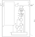
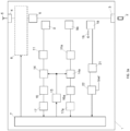
- Figure 3 shows a schematic block diagram of a circuit arrangement 1 according to the invention in a further embodiment.
- the circuit arrangement 1 shown is essentially like the one in Figure 2
- the circuit arrangement 1 shown in FIG. 1 is formed, with reference to the corresponding explanations.
- the circuit arrangement 1 shown comprises the Figure 3 illustrated embodiment no switching element 10 for connecting the signal coupler 9 to the bypass device 11.
- a detection section and a monitoring section advantageously enables the simultaneous identification of frequency bands FB1, FB2, FB3 or channels K1,..., K6 of the frequency bands FB1, FB2, FB3 in which signals are transmitted, for example, by setting different frequencies of the reference signal and cutoff frequencies of the filter device 16.
- an already identified frequency band FB1, FB2, FB3 or an already identified channel K1,..., K6 can continue to be monitored, for example, by continuously or periodically determining the signal power of the signal transmitted in this identified frequency band FB1, FB2, FB3 or channel K1,..., K6.
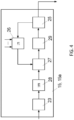
- An input signal of this further frequency divider 28 is an oscillation signal, in particular a sine signal, which can be generated by a corresponding signal source, in particular by a quartz crystal or a quartz oscillator 23.
- the signal source can be part of the control and evaluation device 7 or can be formed separately therefrom.
- An output signal of the phase comparator 27 is fed to a loop filter 29, whose output signal in turn adjusts the controllable oscillator 25, in particular a capacitance of a varactor diode.
- the frequency of the reference signal can be set to the minimum frequency, i.e., the initial frequency, of the first frequency band FB1 in the band identification step.
- a cutoff frequency of the filter device 16 can then be set, for example, to the value of the bandwidth of the first frequency band FB1. If it is then detected that the signal power of the signal provided by the device 17 is greater than or equal to a predetermined threshold, it is identified that a signal is being transmitted in this first frequency band FB1.
- the correspondingly set frequency of the reference signal as well as the cutoff frequency can be stored, for example by the control and evaluation device 7.
- the identification can then either be ended or a further band identification step or a further channel identification step can be carried out, for example in order to identify frequency bands FB1, FB2, FB3 or channels K1,..., K6 in which further signals are being transmitted, in particular simultaneously, via the circuit arrangement 1.
- the frequency of the reference signal can be set to a band start frequency, e.g., 1920 MHz, or a band end frequency, e.g., 1980 MHz, and the cutoff frequency of the low-pass filter device 16 can be set to 60 MHz.
- a signal power of the filtered signal is determined.
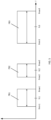
- the signal power is compared with a predetermined threshold value (identification threshold value), wherein, depending on the frequency of the reference signal, a frequency band FB1, FB2, FB3 (see Figure 5 ) or a channel K1,..., K6 assigned to this frequency is identified as a frequency band/channel, in this case the first frequency band, in which a signal is transmitted when the signal power is higher than or equal to the predetermined threshold.
- a predetermined threshold value identification threshold value
- the sequence from the first to the sixth step S1,..., S6 can also be referred to as a band or channel identification step.
- a further band or channel indication step can be performed, for example, to identify a frequency band/channel in which another signal is transmitted or to identify a channel in which a signal of an identified frequency band FB1, FB2, FB3 is transmitted.
- the frequency of the reference signal and the cutoff frequency of the filter device 16 can be changed.
- the frequency of the reference signal can be set to the corresponding band start frequency, e.g. 1710 MHz, or the corresponding band end frequency, e.g. 1785 MHz, and the cutoff frequency of the filter device 16 can be set to the corresponding bandwidth, e.g. 75 MHz.
- the corresponding frequency of the reference signal and the corresponding cutoff frequency of the filter device 16 can also be set for several bands/channels, as explained, and the band-specific signal power of the filtered signal can be determined and stored. Then, the frequency band/channel in which a signal transmission takes place can be identified as the frequency band/channel to which the maximum band-specific signal power is assigned and/or to which a band-specific signal power is assigned and the is more than a predetermined amount greater than the band-specific signal powers assigned to the other frequency bands/channels.
- the described identification of a frequency band/channel or several frequency bands/channels in which a signal transmission takes place takes place in less than a predetermined period of time, which may be e.g. 10 ms.
- a frequency band in which a signal transmission takes place has been identified, then a frequency band-specific channel or multiple frequency band-specific channels of the identified frequency band and their respective channel bandwidths in which the signal transmission takes place can be identified. This can be done in a so-called channel identification step.
- the cutoff frequency of the filter device 16 can be set to a predetermined grid step size, e.g., 200 kHz. Then, starting at the band start frequency of the identified frequency band, the frequency of the reference signal can be incremented in increments by the predetermined grid step size up to the band end frequency, wherein for each of these reference signals set in this way, the signal power of the filtered signal is determined and stored as the segment power, wherein the signal power is also determined for the band start frequency.
- the reference signal can be generated for each of the set frequencies for a predetermined period of time, which can depend on the settling time of the device for generating the reference signal, the measurement time of the device for determining the signal, and the evaluation time required by the control and evaluation device. After this period of time has elapsed, the corresponding incrementation can take place.
- the frequency band is continuously stepped through, with the filtered signal power being determined for 200 kHz wide segments of the frequency band.
- the channel(s) and the corresponding bandwidth in which signal transmission takes place can be identified.
Landscapes
- Engineering & Computer Science (AREA)
- Computer Networks & Wireless Communication (AREA)
- Signal Processing (AREA)
- Transmitters (AREA)
- Transceivers (AREA)
Claims (15)
- Agencement de circuit (1) pour la transmission de signaux de liaison montante et de liaison descendante entre au moins un terminal (2) et au moins une antenne (5), dans lequel l'agencement de circuit (1) comprend au moins un coupleur de signaux (9) pour la mise à disposition d'un signal de liaison montante ou de liaison descendante découplé,
caractérisé en ce que
l'agencement de circuit (1) comprend au moins un appareil (15) pour la mise à disposition d'un signal de référence avec au moins deux ou plusieurs fréquences réglables, dans lequel l'agencement de circuit (1) comprend au moins un mélangeur (14) pour le mélange du signal découplé et du signal de référence et au moins un appareil de filtre (16) pour le filtrage passe-bas ou passe-bande du signal mélangé, dans lequel l'agencement de circuit (1) comprend au moins un appareil d'évaluation (7) pour l'évaluation du signal filtré, qui est conçu pour identifier, lorsqu'une puissance de signal du signal filtré pour une des fréquences réglées du signal de référence est supérieure à une valeur seuil, la bande de fréquences dans laquelle le signal transmis est transmis comme la bande de fréquences à laquelle une des fréquences réglées du signal de référence est attribuée. - Agencement de circuit selon la revendication 1, caractérisé en ce que l'agencement de circuit (1) comprend un appareil (17) pour la détermination d'une puissance de signal du signal filtré.
- Agencement de circuit selon l'une quelconque des revendications précédentes, caractérisé en ce que l'agencement de circuit est conçu de sorte qu'une fréquence limite de l'appareil de filtre (16) peut être réglée.
- Agencement de circuit selon l'une quelconque des revendications précédentes, caractérisé en ce que l'appareil (15) pour la mise à disposition du signal de référence est conçu comme une boucle à verrouillage de phase ou en comprend une telle.
- Agencement de circuit selon l'une quelconque des revendications précédentes, caractérisé en ce que l'agencement de circuit (1) comprend au moins un appareil de commande (7) pour le réglage de la fréquence du signal de référence et/ou pour le réglage de la fréquence limite de l'appareil de filtre (16).
- Agencement de circuit selon l'une quelconque des revendications précédentes, caractérisé en ce que l'agencement de circuit (1) comprend au moins un appareil de détection de transmission de signal.
- Agencement de circuit selon l'une quelconque des revendications précédentes, caractérisé en ce que l'agencement de circuit (1) comprend au moins un élément de commutation (10), dans lequel un premier raccord (9a) du coupleur de signaux (9) est connecté au mélangeur (14) dans un premier état de commutation de l'élément de commutation (10) et un raccord supplémentaire (9b) du coupleur de signaux (9) est connecté au mélangeur (14) dans un état de commutation supplémentaire de l'élément de commutation (10).
- Agencement de circuit selon l'une quelconque des revendications précédentes, caractérisé en ce que l'agencement de circuit (1) comprend un appareil de dérivation (11), dans lequel un signal est transmis entre le coupleur de signaux (9) et le mélangeur (14) par l'intermédiaire de l'appareil de dérivation (11).
- Agencement de circuit selon l'une quelconque des revendications précédentes, caractérisé en ce que l'agencement de circuit est conçu de sorte qu'en fonction de la fréquence réglée et de la au moins une propriété de signal, au moins un canal (K1, ... , K6) peut en outre être identifié, dans lequel le signal transmis est transmis, dans lequel l'agencement de circuit est facultativement conçu de sorte que le canal (K1, ..., K6) peut en outre être identifié en fonction de la fréquence limite réglée de l'appareil de filtre (16).
- Agencement de circuit selon la revendication 9, caractérisé en ce que l'agencement de circuit est conçu de sorte qu'une largeur de bande de canal du canal identifié peut en outre être déterminée.
- Procédé d'identification d'une bande de fréquences (FB1, FB2, FB3) dans laquelle un signal de liaison montante ou de liaison descendante est transmis, dans lequel- un signal de liaison montante ou de liaison descendante découplé est mis à disposition,- au moins un signal de référence avec une fréquence prédéterminée est mis à disposition,- le signal découplé et le signal de référence sont mélangés,- le signal mélangé est filtré,- au moins une propriété de signal du signal filtré est déterminée,- si une puissance de signal du signal filtré pour une des fréquences réglées du signal de référence est supérieure à une valeur seuil, la bande de fréquences dans laquelle le signal transmis est transmis est identifiée comme la bande de fréquences à laquelle une des fréquences réglées du signal de référence est attribuée.
- Procédé selon la revendication 11, caractérisé en ce que des signaux de référence spécifiques à la fréquence sont générés avec différentes fréquences, dans lequel les signaux de référence spécifiques à la fréquence sont respectivement mélangés avec le signal découplé, les signaux mélangés spécifiques à la fréquence sont filtrés et au moins une propriété de signal des signaux mélangés spécifiques à la fréquence est déterminée, dans lequel la bande de fréquences (FB1, FB2, FB3) est déterminée en fonction des propriétés de signal spécifiques à la fréquence.
- Procédé selon la revendication 11 ou 12, caractérisé en ce qu'au moins une fréquence limite d'un filtre (16) est modifiée pour mettre à disposition le signal filtré.
- Procédé selon l'une quelconque des revendications 11 à 13, caractérisé en ce que la bande de fréquences (FB1, FB2, FB3) est identifiée, dans lequel un canal (K1, ... , K6) de cette bande de fréquences (FB1, FB2, FB3) est ensuite identifié, dans lequel une largeur de bande de canal du canal (K1, ... , K6) est facultativement identifiée.
- Procédé selon l'une quelconque des revendications 11 à 14, caractérisé en ce qu'après l'identification d'une bande de fréquences (FB1, FB2, FB3) ou du canal (K1, ... , K6) du signal transmis, une surveillance d'au moins une propriété de signal et/ou l'identification d'une bande de fréquences supplémentaire (FB1, FB2, FB3) ou d'un canal supplémentaire (K1, ... , K6) est lancée, dans lequel une surveillance et l'identification d'une bande de fréquences supplémentaire (FB1, FB2, FB3) ou d'un canal supplémentaire (K1, ... , K6) sont facultativement effectuées de manière séquentielle ou simultanée.
Applications Claiming Priority (2)
| Application Number | Priority Date | Filing Date | Title |
|---|---|---|---|
| DE102019220166.0A DE102019220166A1 (de) | 2019-12-19 | 2019-12-19 | Schaltungsanordnung und Verfahren zur Identifizierung eines Frequenzbands oder Kanals |
| PCT/EP2020/087059 WO2021123193A1 (fr) | 2019-12-19 | 2020-12-18 | Agencement de circuit et procédé d'identification d'une bande ou d'un canal de fréquences |
Publications (2)
| Publication Number | Publication Date |
|---|---|
| EP4078821A1 EP4078821A1 (fr) | 2022-10-26 |
| EP4078821B1 true EP4078821B1 (fr) | 2025-07-02 |
Family
ID=74175767
Family Applications (1)
| Application Number | Title | Priority Date | Filing Date |
|---|---|---|---|
| EP20838958.5A Active EP4078821B1 (fr) | 2019-12-19 | 2020-12-18 | Agencement de circuit et procédé d'identification d'une bande ou d'un canal de fréquences |
Country Status (6)
| Country | Link |
|---|---|
| US (1) | US12218739B2 (fr) |
| EP (1) | EP4078821B1 (fr) |
| JP (1) | JP7462746B2 (fr) |
| CN (1) | CN115298964B (fr) |
| DE (1) | DE102019220166A1 (fr) |
| WO (1) | WO2021123193A1 (fr) |
Family Cites Families (14)
| Publication number | Priority date | Publication date | Assignee | Title |
|---|---|---|---|---|
| KR20020054149A (ko) * | 2000-12-27 | 2002-07-06 | 엘지전자 주식회사 | 디지털 전치왜곡기를 갖는 기지국 송신장치 |
| EP1679802A1 (fr) * | 2005-01-07 | 2006-07-12 | Success Chip Ltd., c/o Offshore Incorporations Ltd., P.O. Box 957, Offshore Incorporations Center | Appareil et procédé pour la réception et transmission de signaux |
| JP4246755B2 (ja) * | 2006-05-30 | 2009-04-02 | 株式会社エヌ・ティ・ティ・ドコモ | 受信信号周波数帯域検出器 |
| JP5555208B2 (ja) * | 2011-07-15 | 2014-07-23 | 日本電信電話株式会社 | 受信システム |
| JP2013187671A (ja) * | 2012-03-07 | 2013-09-19 | Nec Saitama Ltd | 無線中継増幅装置及び無線中継増幅方法 |
| KR101585846B1 (ko) * | 2013-12-31 | 2016-01-15 | 주식회사 엔젤해피 | 직교 주파수 분할 듀플렉싱을 이용한 무선 송수신 장치 및 방법 |
| DE102014213933A1 (de) * | 2014-07-17 | 2016-01-21 | Novero Dabendorf Gmbh | Signalkopplungseinrichtung und Verfahren zum Betrieb einer Signalkopplungseinrichtung |
| US20170257833A1 (en) | 2016-03-02 | 2017-09-07 | Commscope Technologies Llc | Signal detection from digital interface |
| CN109328440A (zh) * | 2016-04-05 | 2019-02-12 | 威尔逊电子有限责任公司 | 用于网络保护的窄带信号检测 |
| KR101954227B1 (ko) * | 2017-04-28 | 2019-05-17 | 주식회사 케이티 | 무선 중계 장치 및 그 동작 방법 |
| DE102017209209A1 (de) * | 2017-05-31 | 2018-12-06 | Laird Dabendorf Gmbh | Signalkopplungsvorrichtung und Verfahren zum Betrieb einer Signalkopplungsvorrichtung |
| DE102018002661A1 (de) * | 2018-03-31 | 2019-10-02 | Heinz Lindenmeier | Antennen-Einrichtung für die bidirektionale Kommunikation auf Fahrzeugen |
| CA3135834A1 (fr) * | 2019-04-01 | 2020-10-08 | Wilson Electronics, Llc | Duplexeur combine |
| US11705960B2 (en) * | 2021-06-10 | 2023-07-18 | Adrf Korea, Inc. | Millimeter-wave repeater for intermediate frequency band transmission |
-
2019
- 2019-12-19 DE DE102019220166.0A patent/DE102019220166A1/de active Pending
-
2020
- 2020-12-18 EP EP20838958.5A patent/EP4078821B1/fr active Active
- 2020-12-18 CN CN202080084803.3A patent/CN115298964B/zh active Active
- 2020-12-18 US US17/782,664 patent/US12218739B2/en active Active
- 2020-12-18 JP JP2022523274A patent/JP7462746B2/ja active Active
- 2020-12-18 WO PCT/EP2020/087059 patent/WO2021123193A1/fr not_active Ceased
Also Published As
| Publication number | Publication date |
|---|---|
| EP4078821A1 (fr) | 2022-10-26 |
| US12218739B2 (en) | 2025-02-04 |
| DE102019220166A1 (de) | 2021-06-24 |
| JP2022553267A (ja) | 2022-12-22 |
| US20230013248A1 (en) | 2023-01-19 |
| WO2021123193A1 (fr) | 2021-06-24 |
| CN115298964A (zh) | 2022-11-04 |
| CN115298964B (zh) | 2025-05-30 |
| JP7462746B2 (ja) | 2024-04-05 |
Similar Documents
| Publication | Publication Date | Title |
|---|---|---|
| DE102009018648B4 (de) | Frontendmodul mit Antennentuner | |
| DE60130315T2 (de) | Verfahren und Schaltung zur Reduzierung von Verluste eines Funksenders | |
| EP3170264B1 (fr) | Dispositif de couplage de signaux et procédé de fonctionnement d'un dispositif de couplage de signaux | |
| DE2322238B2 (de) | Antennenanpaßgerät | |
| WO2019086703A1 (fr) | Procédés et dispositifs de détermination d'un domaine de fréquence d'un signal à transmettre | |
| EP3525346B1 (fr) | Compensation d'une atténuation de signal lors de la transmission des signaux d'émission d'un appareil radio mobile | |
| DE212013000183U1 (de) | Drahtlose Kommunikationsvorrichtung mit einer integrierten Hochfrequenzschaltung RFIC | |
| EP3547561A1 (fr) | Agencement d'antenne pour la communication bidirectionnelle de véhicules | |
| EP3635873B1 (fr) | Procédé et dispositifs d'amplification de signaux radioélectriques entre un appareil terminal et une antenne dans une première bande de fréquences et dans une seconde bande de fréquences | |
| WO2012045526A1 (fr) | Dispositif de transmission sans fil d'informations, terminal de communication pour la transmission sans fil d'informations, ainsi que procédé d'adaptation d'impédance | |
| EP3269184B1 (fr) | Dispositif et procédé d'adaptation de puissance d'un réseau wlan | |
| EP3794750A1 (fr) | Unité d'antenne, système d'émission et procédé de fonctionnement d'une unité d'antenne | |
| EP3642964B1 (fr) | Procédé et dispositif d'amplification de signaux radioélectriques entre un appareil terminal et une antenne | |
| DE102015105166A1 (de) | Systeme und verfahren zum steigern der wahrscheinlichkeit interner messungen in gedrängten umgebungen | |
| EP4078821B1 (fr) | Agencement de circuit et procédé d'identification d'une bande ou d'un canal de fréquences | |
| DE69125951T2 (de) | Verfahren und einrichtung zur identifizierung eines überwachungssignals in einer basisstation eines funktelefonsystems | |
| EP3824561B1 (fr) | Dispositif pour un véhicule destiné à transmettre des données sans contact | |
| EP3410606B1 (fr) | Dispositif de couplage du signal et procédé de fonctionnement d'un dispositif de couplage du signal | |
| DE102017131088A1 (de) | Mobilfunkkompensator zum Einsatz in Kraftfahrzeugen und ein solches Kraftfahrzeug | |
| EP3707867B1 (fr) | Procédé et dispositif de détermination du type de modulation d'un signal et de configuration d'une unité d'amplification | |
| EP3987666A1 (fr) | Ensemble circuit servant à la transmission de signaux radio et procédé de fonctionnement d'un ensemble circuit | |
| DE102013000270B4 (de) | Kompensationsverstärkungsschaltung zum Einbau in eine Übertragungsleitung zwischen einem in einem Kraftfahrzeug befindlichen Mobilfunkgerät bzw. einer kraftfahrzeugseitigen Aufnahme für das Mobilfunkgerät einerseits und einer Antenne des Kraftfahrzeugs andererseits und Verfahren zum Betrieb einer entsprechenden bidirektionalen Kompensationsverstärkungsschaltung | |
| DE69112381T2 (de) | Basisstation für funksystem. | |
| WO2010000690A1 (fr) | Ensemble récepteur, en particulier à utiliser dans des véhicules à moteur | |
| DE10052719B4 (de) | Filter für elektromagnetisch übertragene Signale |
Legal Events
| Date | Code | Title | Description |
|---|---|---|---|
| STAA | Information on the status of an ep patent application or granted ep patent |
Free format text: STATUS: UNKNOWN |
|
| STAA | Information on the status of an ep patent application or granted ep patent |
Free format text: STATUS: THE INTERNATIONAL PUBLICATION HAS BEEN MADE |
|
| PUAI | Public reference made under article 153(3) epc to a published international application that has entered the european phase |
Free format text: ORIGINAL CODE: 0009012 |
|
| STAA | Information on the status of an ep patent application or granted ep patent |
Free format text: STATUS: REQUEST FOR EXAMINATION WAS MADE |
|
| 17P | Request for examination filed |
Effective date: 20220331 |
|
| AK | Designated contracting states |
Kind code of ref document: A1 Designated state(s): AL AT BE BG CH CY CZ DE DK EE ES FI FR GB GR HR HU IE IS IT LI LT LU LV MC MK MT NL NO PL PT RO RS SE SI SK SM TR |
|
| DAV | Request for validation of the european patent (deleted) | ||
| DAX | Request for extension of the european patent (deleted) | ||
| RAP3 | Party data changed (applicant data changed or rights of an application transferred) |
Owner name: MOLEX TECHNOLOGIES GMBH |
|
| P01 | Opt-out of the competence of the unified patent court (upc) registered |
Effective date: 20230528 |
|
| STAA | Information on the status of an ep patent application or granted ep patent |
Free format text: STATUS: EXAMINATION IS IN PROGRESS |
|
| 17Q | First examination report despatched |
Effective date: 20240701 |
|
| GRAP | Despatch of communication of intention to grant a patent |
Free format text: ORIGINAL CODE: EPIDOSNIGR1 |
|
| STAA | Information on the status of an ep patent application or granted ep patent |
Free format text: STATUS: GRANT OF PATENT IS INTENDED |
|
| INTG | Intention to grant announced |
Effective date: 20250227 |
|
| GRAS | Grant fee paid |
Free format text: ORIGINAL CODE: EPIDOSNIGR3 |
|
| GRAA | (expected) grant |
Free format text: ORIGINAL CODE: 0009210 |
|
| STAA | Information on the status of an ep patent application or granted ep patent |
Free format text: STATUS: THE PATENT HAS BEEN GRANTED |
|
| RAP1 | Party data changed (applicant data changed or rights of an application transferred) |
Owner name: MOLEX, LLC |
|
| AK | Designated contracting states |
Kind code of ref document: B1 Designated state(s): AL AT BE BG CH CY CZ DE DK EE ES FI FR GB GR HR HU IE IS IT LI LT LU LV MC MK MT NL NO PL PT RO RS SE SI SK SM TR |
|
| REG | Reference to a national code |
Ref country code: GB Ref legal event code: FG4D Free format text: NOT ENGLISH |
|
| REG | Reference to a national code |
Ref country code: CH Ref legal event code: EP |
|
| REG | Reference to a national code |
Ref country code: DE Ref legal event code: R096 Ref document number: 502020011361 Country of ref document: DE |
|
| REG | Reference to a national code |
Ref country code: IE Ref legal event code: FG4D Free format text: LANGUAGE OF EP DOCUMENT: GERMAN |
|
| REG | Reference to a national code |
Ref country code: NL Ref legal event code: MP Effective date: 20250702 |
|
| PG25 | Lapsed in a contracting state [announced via postgrant information from national office to epo] |
Ref country code: PT Free format text: LAPSE BECAUSE OF FAILURE TO SUBMIT A TRANSLATION OF THE DESCRIPTION OR TO PAY THE FEE WITHIN THE PRESCRIBED TIME-LIMIT Effective date: 20251103 |
|
| PG25 | Lapsed in a contracting state [announced via postgrant information from national office to epo] |
Ref country code: NL Free format text: LAPSE BECAUSE OF FAILURE TO SUBMIT A TRANSLATION OF THE DESCRIPTION OR TO PAY THE FEE WITHIN THE PRESCRIBED TIME-LIMIT Effective date: 20250702 |
|
| PG25 | Lapsed in a contracting state [announced via postgrant information from national office to epo] |
Ref country code: IS Free format text: LAPSE BECAUSE OF FAILURE TO SUBMIT A TRANSLATION OF THE DESCRIPTION OR TO PAY THE FEE WITHIN THE PRESCRIBED TIME-LIMIT Effective date: 20251102 |
|
| PGFP | Annual fee paid to national office [announced via postgrant information from national office to epo] |
Ref country code: DE Payment date: 20250930 Year of fee payment: 6 |
|
| PG25 | Lapsed in a contracting state [announced via postgrant information from national office to epo] |
Ref country code: NO Free format text: LAPSE BECAUSE OF FAILURE TO SUBMIT A TRANSLATION OF THE DESCRIPTION OR TO PAY THE FEE WITHIN THE PRESCRIBED TIME-LIMIT Effective date: 20251002 |
|
| REG | Reference to a national code |
Ref country code: LT Ref legal event code: MG9D |
|
| PG25 | Lapsed in a contracting state [announced via postgrant information from national office to epo] |
Ref country code: FI Free format text: LAPSE BECAUSE OF FAILURE TO SUBMIT A TRANSLATION OF THE DESCRIPTION OR TO PAY THE FEE WITHIN THE PRESCRIBED TIME-LIMIT Effective date: 20250702 |
|
| PG25 | Lapsed in a contracting state [announced via postgrant information from national office to epo] |
Ref country code: HR Free format text: LAPSE BECAUSE OF FAILURE TO SUBMIT A TRANSLATION OF THE DESCRIPTION OR TO PAY THE FEE WITHIN THE PRESCRIBED TIME-LIMIT Effective date: 20250702 |
|
| PG25 | Lapsed in a contracting state [announced via postgrant information from national office to epo] |
Ref country code: GR Free format text: LAPSE BECAUSE OF FAILURE TO SUBMIT A TRANSLATION OF THE DESCRIPTION OR TO PAY THE FEE WITHIN THE PRESCRIBED TIME-LIMIT Effective date: 20251003 |
|
| PG25 | Lapsed in a contracting state [announced via postgrant information from national office to epo] |
Ref country code: SE Free format text: LAPSE BECAUSE OF FAILURE TO SUBMIT A TRANSLATION OF THE DESCRIPTION OR TO PAY THE FEE WITHIN THE PRESCRIBED TIME-LIMIT Effective date: 20250702 Ref country code: CZ Free format text: LAPSE BECAUSE OF FAILURE TO SUBMIT A TRANSLATION OF THE DESCRIPTION OR TO PAY THE FEE WITHIN THE PRESCRIBED TIME-LIMIT Effective date: 20250702 |
|
| PG25 | Lapsed in a contracting state [announced via postgrant information from national office to epo] |
Ref country code: LV Free format text: LAPSE BECAUSE OF FAILURE TO SUBMIT A TRANSLATION OF THE DESCRIPTION OR TO PAY THE FEE WITHIN THE PRESCRIBED TIME-LIMIT Effective date: 20250702 |
|
| PG25 | Lapsed in a contracting state [announced via postgrant information from national office to epo] |
Ref country code: BG Free format text: LAPSE BECAUSE OF FAILURE TO SUBMIT A TRANSLATION OF THE DESCRIPTION OR TO PAY THE FEE WITHIN THE PRESCRIBED TIME-LIMIT Effective date: 20250702 Ref country code: PL Free format text: LAPSE BECAUSE OF FAILURE TO SUBMIT A TRANSLATION OF THE DESCRIPTION OR TO PAY THE FEE WITHIN THE PRESCRIBED TIME-LIMIT Effective date: 20250702 |
|
| PG25 | Lapsed in a contracting state [announced via postgrant information from national office to epo] |
Ref country code: RS Free format text: LAPSE BECAUSE OF FAILURE TO SUBMIT A TRANSLATION OF THE DESCRIPTION OR TO PAY THE FEE WITHIN THE PRESCRIBED TIME-LIMIT Effective date: 20251002 |
|
| PG25 | Lapsed in a contracting state [announced via postgrant information from national office to epo] |
Ref country code: ES Free format text: LAPSE BECAUSE OF FAILURE TO SUBMIT A TRANSLATION OF THE DESCRIPTION OR TO PAY THE FEE WITHIN THE PRESCRIBED TIME-LIMIT Effective date: 20250702 |
|
| PG25 | Lapsed in a contracting state [announced via postgrant information from national office to epo] |
Ref country code: RO Free format text: LAPSE BECAUSE OF FAILURE TO SUBMIT A TRANSLATION OF THE DESCRIPTION OR TO PAY THE FEE WITHIN THE PRESCRIBED TIME-LIMIT Effective date: 20250702 |
|
| PG25 | Lapsed in a contracting state [announced via postgrant information from national office to epo] |
Ref country code: SM Free format text: LAPSE BECAUSE OF FAILURE TO SUBMIT A TRANSLATION OF THE DESCRIPTION OR TO PAY THE FEE WITHIN THE PRESCRIBED TIME-LIMIT Effective date: 20250702 |
|
| PG25 | Lapsed in a contracting state [announced via postgrant information from national office to epo] |
Ref country code: DK Free format text: LAPSE BECAUSE OF FAILURE TO SUBMIT A TRANSLATION OF THE DESCRIPTION OR TO PAY THE FEE WITHIN THE PRESCRIBED TIME-LIMIT Effective date: 20250702 |
|
| PG25 | Lapsed in a contracting state [announced via postgrant information from national office to epo] |
Ref country code: IT Free format text: LAPSE BECAUSE OF FAILURE TO SUBMIT A TRANSLATION OF THE DESCRIPTION OR TO PAY THE FEE WITHIN THE PRESCRIBED TIME-LIMIT Effective date: 20250702 |
|
| PG25 | Lapsed in a contracting state [announced via postgrant information from national office to epo] |
Ref country code: EE Free format text: LAPSE BECAUSE OF FAILURE TO SUBMIT A TRANSLATION OF THE DESCRIPTION OR TO PAY THE FEE WITHIN THE PRESCRIBED TIME-LIMIT Effective date: 20250702 Ref country code: SK Free format text: LAPSE BECAUSE OF FAILURE TO SUBMIT A TRANSLATION OF THE DESCRIPTION OR TO PAY THE FEE WITHIN THE PRESCRIBED TIME-LIMIT Effective date: 20250702 |