EP4079095B1 - Assistance de réseau pour résoudre des conflits de signal de réveil - Google Patents
Assistance de réseau pour résoudre des conflits de signal de réveil Download PDFInfo
- Publication number
- EP4079095B1 EP4079095B1 EP20709708.0A EP20709708A EP4079095B1 EP 4079095 B1 EP4079095 B1 EP 4079095B1 EP 20709708 A EP20709708 A EP 20709708A EP 4079095 B1 EP4079095 B1 EP 4079095B1
- Authority
- EP
- European Patent Office
- Prior art keywords
- wake
- network
- signal
- during
- failure
- Prior art date
- Legal status (The legal status is an assumption and is not a legal conclusion. Google has not performed a legal analysis and makes no representation as to the accuracy of the status listed.)
- Active
Links
Images


Classifications
-
- H—ELECTRICITY
- H04—ELECTRIC COMMUNICATION TECHNIQUE
- H04W—WIRELESS COMMUNICATION NETWORKS
- H04W76/00—Connection management
- H04W76/20—Manipulation of established connections
- H04W76/28—Discontinuous transmission [DTX]; Discontinuous reception [DRX]
-
- H—ELECTRICITY
- H04—ELECTRIC COMMUNICATION TECHNIQUE
- H04W—WIRELESS COMMUNICATION NETWORKS
- H04W52/00—Power management, e.g. Transmission Power Control [TPC] or power classes
- H04W52/02—Power saving arrangements
- H04W52/0209—Power saving arrangements in terminal devices
- H04W52/0225—Power saving arrangements in terminal devices using monitoring of external events, e.g. the presence of a signal
- H04W52/0229—Power saving arrangements in terminal devices using monitoring of external events, e.g. the presence of a signal where the received signal is a wanted signal
- H04W52/0232—Power saving arrangements in terminal devices using monitoring of external events, e.g. the presence of a signal where the received signal is a wanted signal according to average transmission signal activity
-
- H—ELECTRICITY
- H04—ELECTRIC COMMUNICATION TECHNIQUE
- H04L—TRANSMISSION OF DIGITAL INFORMATION, e.g. TELEGRAPHIC COMMUNICATION
- H04L5/00—Arrangements affording multiple use of the transmission path
- H04L5/003—Arrangements for allocating sub-channels of the transmission path
- H04L5/0048—Allocation of pilot signals, i.e. of signals known to the receiver
- H04L5/0051—Allocation of pilot signals, i.e. of signals known to the receiver of dedicated pilots, i.e. pilots destined for a single user or terminal
-
- Y—GENERAL TAGGING OF NEW TECHNOLOGICAL DEVELOPMENTS; GENERAL TAGGING OF CROSS-SECTIONAL TECHNOLOGIES SPANNING OVER SEVERAL SECTIONS OF THE IPC; TECHNICAL SUBJECTS COVERED BY FORMER USPC CROSS-REFERENCE ART COLLECTIONS [XRACs] AND DIGESTS
- Y02—TECHNOLOGIES OR APPLICATIONS FOR MITIGATION OR ADAPTATION AGAINST CLIMATE CHANGE
- Y02D—CLIMATE CHANGE MITIGATION TECHNOLOGIES IN INFORMATION AND COMMUNICATION TECHNOLOGIES [ICT], I.E. INFORMATION AND COMMUNICATION TECHNOLOGIES AIMING AT THE REDUCTION OF THEIR OWN ENERGY USE
- Y02D30/00—Reducing energy consumption in communication networks
- Y02D30/70—Reducing energy consumption in communication networks in wireless communication networks
Definitions
- the invention relates to performing on-duration monitoring based on detection of a failure of network node channel access and, more specifically, relate to performing on-duration monitoring based on detection of a failure of network node channel access during or preceding a wake-up signal occasion.
- UE user equipment
- UL uplink
- DL downlink
- 5G New Radio is part of a continuous mobile broadband evolution promulgated by Third Generation Partnership Project (3GPP) to meet new requirements associated with latency, reliability, security, scalability (e.g., with Internet of Things (IoT)), and other requirements.
- 3GPP Third Generation Partnership Project
- Some aspects of 5G NR may be based on the 4G Long Term Evolution (LTE) standard.
- LTE Long Term Evolution
- Example embodiments of the invention work to improve at least operations in particular associated with failures in such radio technology communications.
- the invention provides an apparatus, comprising: means for detecting, by a network device of a communication network, at least one listen-before-talk failure of network node channel access during or preceding a wake-up signal occasion by determining a lack of detection of one or more signals or channels of a synchronization signal block during a discovery reference signal window that is one of during or preceding the wake-up signal occasion; and means for performing on-duration monitoring based on the detecting.
- Preferred embodiments of the apparatus of claim 1 are defined by claims 2 to 6.
- the invention provides an apparatus, comprising: means for determining, by a network node of a communication network, information comprising a configuration for at least one network device of the communication network for performing on-duration monitoring if a listen-before-talk failure of network node channel access is detected by the at least one network device during or preceding a wake-up signal occasion by determining a lack of detection of one or more signals or channels of a synchronization signal block during a discovery reference signal window that is one of during or preceding the wake-up signal occasion; and means for sending an indication of the information towards the at least one network device.
- Preferred embodiments of the apparatus of claim 7 are defined by claims 8 to 10.
- At least method and apparatus to at least perform on-duration monitoring based on detection of a failure of network node channel access during or preceding a wake-up signal occasion.
- a WUS is designed to allow the UE to skip PDCCH monitoring during DRX OnDurations when there is no data transmission to be done. This monitoring can be performed during a PDCCH occasion time duration (e.g., one or a consecutive number of symbols) during which a MAC entity associated with the UE is configured to monitor the PDCCH.
- PDCCH occasion time duration e.g., one or a consecutive number of symbols
- DRX OnDuration may refer to starting a timer (e.g., drx-onDurationTimer ) during which the UE is in DRX Active Time and monitors PDCCH.
- WUS may refer to signaling by the NW to the UE based on which the UE starts the timer for the next DRX OnDuration.
- Such signaling by the NW may be conducted by means of L1 signaling (e.g., by Downlink Control Information - DCI), by means of MAC signaling (e.g., by MAC Control Element), or by means of RRC signaling.
- the WUS may be L1 signaling DCI with CRC scrambled by PS-RNTI based on which the UE decodes the DCI with such WUS control information.
- the control information may be in form of a bit indicting wake-up or not.
- the WUS may also be called as WUI (Wake Up Indication), PSI (Power Saving Indication), or DCP (DCI with CRC scrambled by PS-RNTI).
- the PS-RNTI may be defined as UE identification for indicating a UE to monitor PDCCH on the next occurrence of the connected mode DRX on-duration.
- the WUS may referred to as "DCI with CRC scrambled by PS-RNTI", where PS-RNTI is the RNTI used to identify the power saving signal for the configured UE.
- a DRX cycle can specify a periodic repetition of the DRX On Duration followed by a possible period of inactivity.
- An onDurationTimer can specify a number of consecutive PDCCH-subframe(s) at the beginning of a DRX Cycle. There can be represented a union over the PDCCH-subframe(s) for serving cells.
- the physical layer may perform a listen-before-talk procedure, according to which transmissions are not performed if a channel is identified as being occupied.
- LBT LTE-LAA LBT mechanism is adopted as baseline for 5GHz band and adopted as the starting point of the design for 6GHz band. At least for band where absence of Wi-Fi cannot be guaranteed (e.g. by regulation), LBT can be performed in units of 20 MHz.
- FIG. 1 shows a Table of Channel access schemes for initiating a COT by gNB as LBE device.
- CAT2 LBT and CAT4 LBT scenario operations for scenarios 110, 120, and 130.
- Scenario 110 of FIG. 1 is for DRS alone or multiplexed with non-unicast data e.g., other system information (OSI), Paging, and/or random access response (RAR).
- scenario 120 of FIG. 1 is for DRS multiplexed with unicast data
- Scenario 130 of FIG. 1 is for PDCCH and PDSCH.
- Scenario 120 and 130 CAT2 LBT is not allowed.
- the channel access schemes for NR-based access for unlicensed spectrum can be classified into the following categories:
- DRS window occur with SSB burst periodicity.
- FIG. 2 shows a DRS window in NR-U.
- Column 210 of FIG. 2 there is scenarios including a DRS-WindowLength-r16, and Discovery Burst - WindowLength-r16.
- Column 220 of FIG. 2 shows resulting additions in ServingCellConfigCommon and ServingCellConfigCommonSIB based on the scenario and also items for further study (FFS) at the time of this application.
- Column 230 of FIG. 2 shows for the scenario a further study (FFS) item at the time of this application with regards to resulting length configurations based on the scenario.
- column 240 of FIG. 2 shows Agreements including that a DRS transmission window duration can be configured as 0.5 1, 2, 3, 4, or 5 ms, if the DRS transmission window duration is not known, a UE may assume the DRS transmission window has a duration of 5 ms.
- WUS monitoring window is an event which starts 0 ms before onDuration period and ends several slots/symbols before onDuration (due to processing time constrains). During that period, UE monitors set of search-space set occasions (one search-space set per CORESET) configured for WUS PS-RNTI.
- an onDurationTimer can specify a number of consecutive PDCCH-subframe(s) at the beginning of a DRX Cycle. While a PDCCH period (pp) can refer to an interval between the start of two consecutive PDCCH occasions and depends on a used PDCCH search space.
- problems with current standards at the time of this application include that for a network there is basic UE behaviour related to WUS.
- This basic behavior includes that in a PDCCH-WUS occasion that a UE is monitoring, if the UE is indicated to wake-up to monitor the PDCCH during the next occurrence of the drx-onDurationTimer. After this, the UE starts the drx-onDurationTimer at its next occasion. Otherwise, if no WUS is received, the UE does not start the timer and does not start the active time.
- Listen Before Talk may fail (channel busy), thus the network will not be able to send a potential WUS signal even if data is pending at the network buffer for the UE.
- a network node such as a RAN2 has not specified anything for WUS in connection with NR-U yet because NR-U is not in scope of the WID on UE Power Saving, within which 3GPP defined WUS.
- WUS can be configured also for NR-U-capable UEs
- no enhancements tailored to NR-U are in current standards at the time of this application.
- the problem of a larger UE power consumption in NR-U compared to NR will however be apparent when NR-U deployments materialize and the UE power saving topic in NR-U will have to be addressed as part of NR maintenance or at later standards body releases or work items.
- a gNB should not transmit periodic signals, unless they are extremely essential (such as SSB and system information) transmitted with CAT2 in DRS limited to 1/20% of time/duty-cycle, i.e. 1ms once 40ms.
- a gNB may configure SSB burst as often as 5ms and however needs to perform CAT4 LBT which is not desirable. Therefore, due to coexistence and to save power, a NR-U gNB would not transmit WUS unless the gNB wants to wake up a UE.
- the network may wait for the next WUS opportunity to indicate the presence of data to achieve a larger UE power saving, whereas in case of "delay stringent” data the network may prefer to send the data during the next OnDuration despite the WUS was not transmitted because of LBT failure in order to avoid increasing latency (despite the UE would waste unnecessarily power in case of no data).
- FIG. 3 Before describing the example embodiments in detail, reference is made to FIG. 3 for illustrating a simplified block diagram of various electronic devices that are suitable for use in practicing the example embodiments.
- FIG. 3 shows a block diagram of one possible and non-limiting exemplary system in which the example embodiments may be practiced.
- a user equipment (UE) 10 is in wireless communication with a wireless network 1.
- a UE is a wireless, typically mobile device that can access a wireless network.
- the UE 10 includes one or more processors DP 10A, one or more memories MEM 10B, and one or more transceivers TRANS 10D interconnected through one or more buses.
- Each of the one or more transceivers TRANS 10D includes a receiver and a transmitter.
- the one or more buses may be address, data, or control buses, and may include any interconnection mechanism, such as a series of lines on a motherboard or integrated circuit, fiber optics or other optical communication equipment, and the like.
- the one or more transceivers TRANS 10D are connected to one or more antennas for communication 11 and 18 to gNB 12 and NN 13, respectively.
- the one or more memories MEM 10B include computer program code PROG 10C.
- the UE 10 communicates with gNB 12 and/or NN 13 via a wireless link 111.
- the gNB 12 (NR/5G Node B or possibly an evolved NB) is a base station such as a master or secondary node base station (e.g., for NR or LTE long term evolution) that communicates with devices such as NN 13 and UE 10 of FIG. 3 .
- the gNB 12 provides access to wireless devices such as the UE 10 to the wireless network 1.
- the gNB 12 includes one or more processors DP 12A, one or more memories MEM 12C, and one or more transceivers TRANS 12D interconnected through one or more buses. In accordance with the example embodiments these TRANS 12D can include X2 and/or Xn interfaces for use to perform the example embodiments.
- Each of the one or more transceivers TRANS 12D includes a receiver and a transmitter.
- the one or more transceivers TRANS 12D are connected to one or more antennas for communication over at least link 11 with the UE 10.
- the one or more memories MEM 12B and the computer program code PROG 12C are configured to cause, with the one or more processors DP 12A, the gNB 12 to perform one or more of the operations as described herein.
- the gNB 12 may communicate with another gNB or eNB, or a device such as the NN 13.
- the link 11 and or any other link may be wired or wireless or both and may implement, e.g., an X2 or Xn interface. Further the link 11 may be through other network devices such as, but not limited to an NCE/MME/SGW device such as the NCE/MME/SGW 14 of FIG. 3 .
- the NN 13 can comprise a mobility function device such as an AMF or SMF, further the NN 13 may comprise a NR/5G Node B or possibly an evolved NB a base station such as a master or secondary node base station (e.g., for NR or LTE long term evolution) that communicates with devices such as the gNB 12 and/or UE 10 and/or the wireless network 1.
- the NN 13 includes one or more processors DP 13A, one or more memories MEM 13B, one or more network interfaces, and one or more transceivers TRANS 12D interconnected through one or more buses.
- these network interfaces of NN 13 can include X2 and/or Xn interfaces for use to perform the example embodiments.
- Each of the one or more transceivers TRANS 13D includes a receiver and a transmitter connected to one or more antennas.
- the one or more memories MEM 13B include computer program code PROG 13C.
- the one or more memories MEM 13B and the computer program code PROG 13C are configured to cause, with the one or more processors DP 13A, the NN 13 to perform one or more of the operations as described herein.
- the NN 13 may communicate with another mobility function device and/or eNB such as the gNB 12 and the UE 10 or any other device using, e.g., link 11 or another link. These links maybe wired or wireless or both and may implement, e.g., an X2 or Xn interface.
- the link 11 may be through other network devices such as, but not limited to an NCE/MME/SGW device such as the NCE/MME/SGW 14 of FIG. 3 .
- the NCE/MME/SGW 14 including MME (Mobility Management Entity)/SGW (Serving Gateway) functionality, such as User Plane Functionalities, and/or an Access Management functionality for LTE and similar functionality for 5G.
- MME Mobility Management Entity
- SGW Serving Gateway
- the one or more buses of the device of FIG. 3 may be address, data, or control buses, and may include any interconnection mechanism, such as a series of lines on a motherboard or integrated circuit, fiber optics or other optical communication equipment, wireless channels, and the like.
- the one or more transceivers TRANS 12D, TRANS 13D and/or TRANS 10D may be implemented as a remote radio head (RRH), with the other elements of the gNB 12 being physically in a different location from the RRH, and the one or more buses 157 could be implemented in part as fiber optic cable to connect the other elements of the gNB 12 to a RRH.
- RRH remote radio head
- FIG. 3 shows a network node or base station such as the gNB 12 as in FIG. 3 and mobility management device such as the NN 13 as in FIG. 3 , these devices can incorporate or be incorporated into an eNodeB or eNB or gNB such as for LTE and NR, and would still be configurable to perform example embodiments as described in this application.
- cells perform functions, but it should be clear that the gNB that forms the cell and/or a user equipment and/or mobility management function device that will perform the functions. In addition, the cell makes up part of a gNB, and there can be multiple cells per gNB.
- the wireless network 1 may include a network control element (NCE/MME/SGW) 14 that may include NCE (Network Control Element), MME (Mobility Management Entity)/SGW (Serving Gateway) functionality, and which provides connectivity with a further network, such as a telephone network and/or a data communications network (e.g., the Internet).
- NCE Network Control Element
- MME Mobility Management Entity
- SGW Serving Gateway
- the gNB 12 and the NN 13 are coupled via a link 13 and/or link 14 to the NCE/MME/SGW 14.
- the operations in accordance with example embodiments, as performed by the NN 13 may also be performed at the NCE/MME/SGW 14.
- the NCE/MME/SGW 14 includes one or more processors DP 14A, one or more memories MEM 14B, and one or more network interfaces (N/W I/F(s)), interconnected through one or more buses coupled with the link 13 and/or 14. In accordance with the example embodiments these network interfaces can include X2 and/or Xn interfaces for use to perform the example embodiments.
- the one or more memories MEM 14B include computer program code PROG 14C.
- the one or more memories MEM14B and the computer program code PROG 14C are configured to, with the one or more processors DP 14A, cause the NCE/MME/SGW 14 to perform one or more operations which may be needed to support the operations in accordance with the example embodiments.
- the wireless Network 1 may implement network virtualization, which is the process of combining hardware and software network resources and network functionality into a single, software-based administrative entity, a virtual network.
- Network virtualization involves platform virtualization, often combined with resource virtualization.
- Network virtualization is categorized as either external, combining many networks, or parts of networks, into a virtual unit, or internal, providing network-like functionality to software containers on a single system. Note that the virtualized entities that result from the network virtualization are still implemented, at some level, using hardware such as processors DP10A, DP12A, DP13A, and/or DP14A and memories MEM 10B, MEM 12B, MEM 13B, and/or MEM 14B, and also such virtualized entities create technical effects.
- the computer readable memories MEM 10B, MEM 12B, MEM 13B, and MEM 14B may be of any type suitable to the local technical environment and may be implemented using any suitable data storage technology, such as semiconductor based memory devices, flash memory, magnetic memory devices and systems, optical memory devices and systems, fixed memory and removable memory.
- the computer readable memories MEM 10B, MEM 12B, MEM 13B, and MEM 14B may be means for performing storage functions.
- the processors DP10A, DP12A, DP13A, and DP14A may be of any type suitable to the local technical environment, and may include one or more of general purpose computers, special purpose computers, microprocessors, digital signal processors (DSPs) and processors based on a multi-core processor architecture, as non-limiting examples.
- the processors DP10A, DP12A, DP13A, and DP14A may be means for performing functions, such as controlling the UE 10, gNB 12, NN 13, NCE/MME/SGW 14 and other functions as described herein.
- Example embodiments provide at least a method and an apparatus with means to control / adapt the start of an OnDurationtimer if UE detects an LBT failure in downlink during WUS occasions preceding the OnDuration (thus leading to the UE not monitoring for receiving the WUS and/or not monitoring or detecting one or more signals or channels to be transmitted during a discovery reference signal window, such as based on PSS/SSS or PBCH associated with an SSB to be transmitted in DRS by gNB).
- a lack of detection in a DRS window can cause the UE or another network device to determine an LBT failure.
- an LBT failure of network node channel access can be detected based on a lack of detection of one or more signals or channels to be transmitted during a discovery reference signal window.
- the claimed invention relates to this embodiment.
- control and adaptation for these operations can be based on the 5QI, 5G QoS Indicator.
- the 5QI, 5G QoS Indicator such as for service latency, such as on the DRX cycle/WUS frequency, and (potentially) accounting also for the number of consecutive LBT failures, according to a network configuration.
- a determined relationship between DRX cycle / WUS frequency and QoS/5QI can also include that it can be determined based on tightness or level of a latency target requirement a length of the DRX cycle. For example the higher the tightness or level of a latency target requirement then the shorter the DRS cycle.
- This determining in accordance with example embodiments can help a network device establish indirectly a dependency between the network indication and a network device QoS profile, for use in operations as disclosed herein.
- Operations in accordance with example embodiments will result for instance in the UE performing DRX-OnDuration monitoring without a preceding WUS indication if one or more LBT failures have been detected during the DRS window preceding the DRX-ONDuration and/or if one or more of the configured DRBs have delay-stringent requirement (e.g. based on QoS/5QI).
- Example embodiments as disclosed herein include that the DRX-OnDurationtimer is not to be started if the UE detects an LBT failure during one or more DRS window(s) preceding the ONDuration.
- the DRS window(s) can be during or preceding a WUS window.
- At least the detecting the LBT failure during these windows can be further depending on the QoS/5QI, and/or depending on the DRS, DRX cycle and/or WUS frequency.
- the NR-U UE can monitor for Listen-Before-Talk (LBT) failure in DL for the purpose of power saving based at least on a DRS window.
- LBT Listen-Before-Talk
- the NR-U UE can monitor for subsequent Listen-Before-Talk (LBT) failure(s) in DL for the purpose of power saving.
- LBT Listen-Before-Talk
- the NR-U UE can monitor for Listen-Before-Talk (LBT) failure(s) in DL for the purpose of power saving only if it is configured to skip starting the DRX-OnDurationtimer.
- LBT Listen-Before-Talk
- the NR-U UE can be configured to skip starting the DRX-OnDurationtimer when detecting LBT failures, it will start the DRX-OnDurationtimer after N+1 subsequent LBT failures observed during DRS windows that occur closest to the WUS occasions/window. This is to maximize the correlation between probability that DRS had LBT failure (as can be measured by UE) and WUS window had LBT failure, as in accordance with example embodiments.
- the above actions may in this way be able to "overwrite" the default UE behaviour, which may be configured through the ps-WakeupOrNot, such that if a UE is configured to continue sleeping in case of not detecting the WUS correctly, the UE may through these triggers still be required to monitor for the PDCCH in the next OnDuration.
- example embodiments can be applicable to improve operations using a WUS design where the PDCCH-WUS and/or DCI with CRC is scrambled by PS-RNTI.
- example embodiments can be applied to advantage any WUS design standards acceptances at the time of this application and/or future standards acceptances.
- the example embodiments can be applicable to improve operations of WUS designs at least such as WUS designs of NB-IoT and/or WUS designs where a WUS is transmitted with a different DCI format than for example but not limited to a format 2_6, or on a different channel than PDCCH, and/or using physical signals/sequences such as DMRS.
- Advantages of operations in accordance with example embodiments as disclosed herein include at least that UE behavior in case the WUS overlaps with certain activities including LBT failure in NR-U is defined and gives more flexibility to the network to determine the best tradeoff between UE power saving and latency targets.
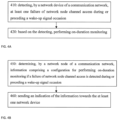
- FIG. 4A illustrates operations in accordance with example embodiments which may be performed by a network device such as, but not limited to, a network device such as a UE 10 as in FIG. 3 .
- a network device such as, but not limited to, a network device such as a UE 10 as in FIG. 3 .
- step 410 of FIG. 4A there is detecting, by a network device of a communication network, at least one failure of network node channel access during or preceding a wake-up signal occasion.
- step 420 of FIG. 4A there is based on the detecting, performing on-duration monitoring.
- the network device is in a sleep mode
- the on-duration monitoring is performed without receiving a preceding wake-up signal indicating wake-up during a wake-up signal occasion associated with the sleep mode.
- the failure is during a discovery reference signal window that is one of during or preceding the wake-up signal occasion.
- failure of network node channel access comprises at least one listen before talk failure of a device of the communication network.
- At least one of detecting or performing on-duration monitoring is based on an indication from the communication network.
- the indication is based on at least one of a discontinuous reception cycle or a wake-up signal frequency associated with the network device, and wherein the indication accounts for a number of consecutive ones of the failure of the network node channel access.
- the on-duration monitoring comprises discontinuous reception on-duration monitoring.
- the performing on-duration monitoring comprises: based on an indication from the communication network, determining to start a discontinuous reception On-duration timer for the on-duration monitoring.
- starting the discontinuous reception On-duration timer is performed after N+1 subsequent listen before talk failures observed during at least one discovery reference signal window that occur closest the wake-up signal occasion.
- determining to start a discontinuous reception for the On-duration monitoring is based on a wake-up signal configuration from the communication network.
- the on-duration monitoring is performed based on determining that the at least one data radio bearer affected by the failure comprises a delay-stringent requirement.
- the delay-stringent requirement comprises at least one of a communication network technology requirement or a quality of service requirement.
- the determined length of the at least one of a discontinuous reception cycle is used to establish a dependency between the indication from the communication network and a quality of service requirement of the network device.
- a non-transitory computer-readable medium (MEM 10B as in FIG. 3 ) storing program code (PROG 10C as in FIG. 3 ), the program code executed by at least one processor (DP 10A as in FIG. 3 ) to perform the operations as at least described in the paragraphs above.
- an apparatus comprising: means for detecting (TRANS 10D, MEM 10B, PROG 10C, and DP 10A as in FIG. 3 ), by a network device (UE 10 as in FIG. 2 ) of a communication network (Network 1 as in FIG. 3 ), at least one failure of network node channel access during or preceding a wake-up signal occasion; and means based on the detecting, for performing (TRANS 10D, MEM 10B, PROG 10C, and DP 10A as in FIG. 3 ) on-duration monitoring.
- At least the means for detecting and performing comprises a non-transitory computer readable medium [MEM 10B] encoded with a computer program [PROG 10C] executable by at least one processor [DP 10A].
- FIG. 4B illustrates operations in accordance with example embodiments which may be performed by a network device such as, but not limited to, a network device such as a gNB 12 or NN 13 as in FIG. 3 .
- a network device such as a gNB 12 or NN 13 as in FIG. 3 .
- step 450 of FIG. 4B there is determining, by a network node of a communication network, information comprising a configuration for performing on-duration monitoring if a failure of network node channel access is detected during or preceding a wake-up signal occasion.
- step 460 of FIG. 4B there is sending an indication of the information towards the at least one network device.
- the configuration is for use while the at least one network device is in a sleep mode, and wherein the configuration is for the on-duration monitoring to be performed without a preceding wake-up signal indicating wake-up during a wake-up signal occasion associated with the sleep mode.
- the configuration is for use for detecting the failure of network node channel access based on a lack of detection of one or more signals or channels to be transmitted during a discovery reference signal window.
- the configuration is for use for detecting the failure of network node channel access during a discovery reference signal window that is one of during or preceding the wake-up signal occasion.
- the configuration is based on at least one of a discontinuous reception cycle or a wake-up signal frequency associated with the at least one network device, and wherein the indication accounts for a number of consecutive ones of the failure of the network node channel access.
- the configuration is for use in determining to start a discontinuous reception On-duration timer for the on-duration monitoring after N+1 subsequent listen before talk failures observed during at least one discovery reference signal window that occur closest to the wake-up signal occasion.
- the information comprises a configuration to start a discontinuous reception On-duration timer for the on-duration monitoring based on a wake-up signal configuration from the communication network.
- the information comprises on-duration monitoring configuration based on at least one data radio bearer affected by the failure comprises a delay-stringent requirement.
- the delay-stringent requirement comprises at least one of a communication network technology requirement or a quality of service requirement.
- the information comprises a configuration to determine, based on a required maximum latency level of the delay-stringent requirement of the at least one data radio bearer affected by the failure, a length of the at least one of a discontinuous reception cycle.
- the determined length of the at least one of a discontinuous reception cycle is used to establish a dependency between the indication from the communication network and a quality of service requirement of the at least one network device.
- a non-transitory computer-readable medium (MEM 12B and/or MEM 13B as in FIG. 3 ) storing program code (PROG 12C and/or PROG 13C as in FIG. 3 ), the program code executed by at least one processor (DP 12A and/or DP 13A as in FIG. 3 ) to perform the operations as at least described in the paragraphs above.
- an apparatus comprising: means for determining (TRANS 12D and/or TRANS 13D, MEM 12B and/or MEM 13B, PROG 12C and/or PROG 13C, and DP 12A and/or DP 13A as in FIG. 3 ), by a network node (gNB 12 and/or NN 13 as in FIG. 3 ) of a communication Network 1 as in FIG. 3 ), information comprising a configuration (MEM 12B and/or MEM 13B, PROG 12C and/or PROG 13C, and DP 12A and/or DP 13A as in FIG.
- UE 10 for use by at least one network device (UE 10 as in FIG.3 ) of the communication network to perform on-duration monitoring if a failure of network node channel access is detected during or preceding a wake-up signal occasion; and means for sending (TRANS 12D and/or TRANS 13D, MEM 12B and/or MEM 13B, PROG 12C and/or PROG 13C, and DP 12A and/or DP 13A as in FIG. 3 ) an indication of the information towards the at least one network device.
- UE 10 as in FIG.3
- means for sending (TRANS 12D and/or TRANS 13D, MEM 12B and/or MEM 13B, PROG 12C and/or PROG 13C, and DP 12A and/or DP 13A as in FIG. 3 ) an indication of the information towards the at least one network device.
- At least the means for determining and sending comprises a non-transitory computer readable medium [MEM 12B and/or MEM 13B as in FIG. 3 ] encoded with a computer program [PROG 12C and/or PROG 13C as in FIG. 3 ] executable by at least one processor [DP 12A and/or DP 13A and in FIG. 3 ].
- the various embodiments may be implemented in hardware or special purpose circuits, software, logic or any combination thereof.
- some aspects may be implemented in hardware, while other aspects may be implemented in firmware or software which may be executed by a controller, microprocessor or other computing device.
- firmware or software which may be executed by a controller, microprocessor or other computing device.
- various aspects may be illustrated and described as block diagrams, flow charts, or using some other pictorial representation, it is well understood that these blocks, apparatus, systems, techniques or methods described herein may be implemented in, as non-limiting examples, hardware, software, firmware, special purpose circuits or logic, general purpose hardware or controller or other computing devices, or some combination thereof.
- Embodiments may be practiced in various components such as integrated circuit modules.
- the design of integrated circuits is by and large a highly automated process.
- Complex and powerful software tools are available for converting a logic level design into a semiconductor circuit design ready to be etched and formed on a semiconductor substrate.
- connection means any connection or coupling, either direct or indirect, between two or more elements, and may encompass the presence of one or more intermediate elements between two elements that are “connected” or “coupled” together.
- the coupling or connection between the elements can be physical, logical, or a combination thereof.
- two elements may be considered to be “connected” or “coupled” together by the use of one or more wires, cables and/or printed electrical connections, as well as by the use of electromagnetic energy, such as electromagnetic energy having wavelengths in the radio frequency region, the microwave region and the optical (both visible and invisible) region, as several non-limiting and non-exhaustive examples.
Landscapes
- Engineering & Computer Science (AREA)
- Signal Processing (AREA)
- Computer Networks & Wireless Communication (AREA)
- Mobile Radio Communication Systems (AREA)
Claims (10)
- Appareil comprenant :des moyens (10A-D) pour détecter, par un dispositif de réseau (10) d'un réseau de communication (1), au moins une défaillance d'écoute avant conversation d'un accès de canal de nœud de réseau pendant ou avant une occasion de signal de réveil, en déterminant une absence de détection d'un ou plusieurs signaux ou canaux d'un bloc de signal de synchronisation dans une fenêtre de signal de référence de découverte qui se situe pendant ou avant l'occasion de signal de réveil ; etdes moyens (10A-D) pour réaliser une surveillance de durée d'activation sur la base de la détection.
- Appareil selon la revendication 1, dans lequel le dispositif de réseau (10) est en mode veille, et dans lequel la surveillance de durée d'activation est réalisée sans recevoir de signal de réveil précédent indiquant le réveil pendant une occasion de signal de réveil associée au mode veille.
- Appareil selon l'une des revendications 1 et 2, dans lequel au moins une parmi la détection de l'au moins une défaillance ou la réalisation de la surveillance de durée d'activation est basée sur une indication du réseau de communication (1).
- Appareil selon la revendication 3, dans lequel l'indication est basée sur au moins un parmi un cycle de réception discontinu ou une fréquence de signal de réveil associée au dispositif de réseau (10), et dans lequel l'indication tient compte d'un certain nombre de défaillances consécutives de l'accès de canal de nœud de réseau.
- Appareil selon l'une des revendications 1 à 4, dans lequel la surveillance de durée d'activation comprend une surveillance de durée d'activation de réception discontinue.
- Appareil selon l'une des revendications 1 à 5, dans lequel les moyens pour réaliser la surveillance de durée d'activation sont en outre configurés pour :
sur la base d'une indication provenant du réseau de communication (1), déterminer de démarrer un temporisateur de durée d'activation de réception discontinue pour la surveillance de durée d'activation. - Appareil comprenant :des moyens (12A-D, 13A-D) pour déterminer, par un nœud de réseau (12, 13) d'un réseau de communication (1), des informations comprenant une configuration pour qu'au moins un dispositif de réseau (10) du réseau de communication (1) réalise une surveillance de durée d'activation si une défaillance d'écoute avant conversation d'un accès de canal de nœud de réseau est détectée par l'au moins un dispositif de réseau (10) pendant ou avant une occasion de signal de réveil, en déterminant une absence de détection d'un ou plusieurs signaux ou canaux d'un bloc de signal de synchronisation dans une fenêtre de signal de référence de découverte qui se situe pendant ou avant l'occasion de signal de réveil ; etdes moyens (12A-D, 13A-D) pour envoyer une indication des informations vers l'au moins un dispositif de réseau (10).
- Appareil selon la revendication 7, dans lequel la configuration est destinée à être utilisée lorsque l'au moins un dispositif de réseau (10) est en mode veille, et dans lequel la configuration est destinée à ce que la surveillance de durée d'activation soit réalisée sans signal de réveil précédent indiquant le réveil pendant une occasion de signal de réveil associée au mode veille.
- Appareil selon l'une des revendications 7 et 8, dans lequel la configuration est basée sur au moins un parmi un cycle de réception discontinu ou une fréquence de signal de réveil associée à l'au moins un dispositif de réseau (10), et dans lequel l'indication tient compte d'un certain nombre de défaillances consécutives de l'accès de canal de nœud de réseau.
- Appareil selon l'une des revendications 7 à 9, dans lequel les informations comprennent une configuration pour démarrer un temporisateur de durée d'activation de réception discontinue pour la surveillance de durée d'activation sur la base d'une configuration de signal de réveil provenant du réseau de communication (1).
Applications Claiming Priority (1)
| Application Number | Priority Date | Filing Date | Title |
|---|---|---|---|
| PCT/IB2020/050985 WO2021156652A1 (fr) | 2020-02-07 | 2020-02-07 | Assistance de réseau pour résoudre des conflits de signal de réveil |
Publications (2)
| Publication Number | Publication Date |
|---|---|
| EP4079095A1 EP4079095A1 (fr) | 2022-10-26 |
| EP4079095B1 true EP4079095B1 (fr) | 2025-06-18 |
Family
ID=69770956
Family Applications (1)
| Application Number | Title | Priority Date | Filing Date |
|---|---|---|---|
| EP20709708.0A Active EP4079095B1 (fr) | 2020-02-07 | 2020-02-07 | Assistance de réseau pour résoudre des conflits de signal de réveil |
Country Status (5)
| Country | Link |
|---|---|
| US (1) | US12349070B2 (fr) |
| EP (1) | EP4079095B1 (fr) |
| JP (1) | JP7471429B2 (fr) |
| CN (1) | CN115066973B (fr) |
| WO (1) | WO2021156652A1 (fr) |
Families Citing this family (3)
| Publication number | Priority date | Publication date | Assignee | Title |
|---|---|---|---|---|
| CN119096579A (zh) * | 2023-04-06 | 2024-12-06 | 北京小米移动软件有限公司 | 信息处理方法、系统及装置、通信设备及存储介质 |
| CN118139190B (zh) * | 2024-02-08 | 2025-06-13 | 荣耀终端股份有限公司 | 一种通信处理方法及通信装置 |
| WO2025251325A1 (fr) * | 2024-06-08 | 2025-12-11 | Qualcomm Incorporated | Signalisation de commande pour des opérations de détection de signal de réveil défaillant |
Family Cites Families (8)
| Publication number | Priority date | Publication date | Assignee | Title |
|---|---|---|---|---|
| WO2014179921A1 (fr) | 2013-05-06 | 2014-11-13 | Broadcom Corporation | Commutateur mode dormant-mode actif |
| US20200068378A1 (en) * | 2016-11-18 | 2020-02-27 | Nokia Technologies Oy | Opportunistic use of drs instances in lte-u stand alone systems |
| US11064437B2 (en) | 2017-01-19 | 2021-07-13 | Nokia Technolgies Oy | Power saving for wireless device |
| US10820299B2 (en) | 2017-11-13 | 2020-10-27 | Qualcomm Incorporated | Radio resource management configuration for user equipment with wake-up signal receivers |
| US10993117B2 (en) * | 2017-12-13 | 2021-04-27 | Apple Inc. | Unlicensed band management control indicators |
| WO2019215670A1 (fr) * | 2018-05-11 | 2019-11-14 | Nokia Technologies Oy | Agencement de canal d'accès aléatoire physique pour une nouvelle radio sans licence |
| EP4055900B1 (fr) * | 2019-11-07 | 2026-01-28 | Apple Inc. | Signalisation d'activation lors d'un cycle de réception discontinue |
| JP7405973B2 (ja) | 2019-11-13 | 2023-12-26 | ノキア テクノロジーズ オサケユイチア | ランダムアクセス応答を有するウェイクアップ信号 |
-
2020
- 2020-02-07 EP EP20709708.0A patent/EP4079095B1/fr active Active
- 2020-02-07 CN CN202080095804.8A patent/CN115066973B/zh active Active
- 2020-02-07 US US17/792,619 patent/US12349070B2/en active Active
- 2020-02-07 WO PCT/IB2020/050985 patent/WO2021156652A1/fr not_active Ceased
- 2020-02-07 JP JP2022547310A patent/JP7471429B2/ja active Active
Also Published As
| Publication number | Publication date |
|---|---|
| CN115066973A (zh) | 2022-09-16 |
| US20230040865A1 (en) | 2023-02-09 |
| EP4079095A1 (fr) | 2022-10-26 |
| WO2021156652A1 (fr) | 2021-08-12 |
| CN115066973B (zh) | 2025-08-12 |
| JP7471429B2 (ja) | 2024-04-19 |
| US12349070B2 (en) | 2025-07-01 |
| JP2023513508A (ja) | 2023-03-31 |
Similar Documents
| Publication | Publication Date | Title |
|---|---|---|
| EP3841820B1 (fr) | Signal de réveil avec réponse d'accès aléatoire | |
| EP3963953B1 (fr) | Détermination de surveillance de pdcch pendant une durée de marche en mode d'économie d'énergie | |
| US12526849B2 (en) | Method and apparatus for more power efficient physical downlink control channel monitoring after a random access transmission | |
| US11751245B2 (en) | Method and wireless communication system for handling timer operation | |
| JP7501638B2 (ja) | 方法及び端末 | |
| US20240155580A1 (en) | Method for obtaining initial bandwidth part configuration, terminal, and network-side device | |
| JP7367061B2 (ja) | ウェイクアップ信号監視指示 | |
| EP3031276B1 (fr) | Réseau de communication, procédé et équipement d'infrastructure | |
| EP3031277B1 (fr) | Dispositif utilisateur permettant de communiquer des données et procédé | |
| WO2021185538A1 (fr) | Extensions de wus pour radiomessagerie pour rrc inactive | |
| EP4079095B1 (fr) | Assistance de réseau pour résoudre des conflits de signal de réveil | |
| US20220369418A1 (en) | Methods and devices for signal processing | |
| CN114616870B (zh) | 非连续接收周期期间的唤醒信令 | |
| CN116234042A (zh) | 一种通信方法及装置 | |
| CN113826421B (zh) | 激活终端的方法及装置 | |
| WO2024060311A1 (fr) | Procédés et appareils d'attribution de ressources dans des spectres sans licence | |
| CN116326181B (zh) | 侧链路通信中的不连续接收 | |
| WO2024065529A1 (fr) | Procédés et appareils pour un mécanisme d'amélioration de surveillance de pdcch pour un trafic xr |
Legal Events
| Date | Code | Title | Description |
|---|---|---|---|
| STAA | Information on the status of an ep patent application or granted ep patent |
Free format text: STATUS: UNKNOWN |
|
| STAA | Information on the status of an ep patent application or granted ep patent |
Free format text: STATUS: THE INTERNATIONAL PUBLICATION HAS BEEN MADE |
|
| PUAI | Public reference made under article 153(3) epc to a published international application that has entered the european phase |
Free format text: ORIGINAL CODE: 0009012 |
|
| STAA | Information on the status of an ep patent application or granted ep patent |
Free format text: STATUS: REQUEST FOR EXAMINATION WAS MADE |
|
| 17P | Request for examination filed |
Effective date: 20220722 |
|
| AK | Designated contracting states |
Kind code of ref document: A1 Designated state(s): AL AT BE BG CH CY CZ DE DK EE ES FI FR GB GR HR HU IE IS IT LI LT LU LV MC MK MT NL NO PL PT RO RS SE SI SK SM TR |
|
| STAA | Information on the status of an ep patent application or granted ep patent |
Free format text: STATUS: EXAMINATION IS IN PROGRESS |
|
| 17Q | First examination report despatched |
Effective date: 20230221 |
|
| DAV | Request for validation of the european patent (deleted) | ||
| DAX | Request for extension of the european patent (deleted) | ||
| GRAP | Despatch of communication of intention to grant a patent |
Free format text: ORIGINAL CODE: EPIDOSNIGR1 |
|
| STAA | Information on the status of an ep patent application or granted ep patent |
Free format text: STATUS: GRANT OF PATENT IS INTENDED |
|
| INTG | Intention to grant announced |
Effective date: 20250130 |
|
| GRAS | Grant fee paid |
Free format text: ORIGINAL CODE: EPIDOSNIGR3 |
|
| GRAA | (expected) grant |
Free format text: ORIGINAL CODE: 0009210 |
|
| STAA | Information on the status of an ep patent application or granted ep patent |
Free format text: STATUS: THE PATENT HAS BEEN GRANTED |
|
| AK | Designated contracting states |
Kind code of ref document: B1 Designated state(s): AL AT BE BG CH CY CZ DE DK EE ES FI FR GB GR HR HU IE IS IT LI LT LU LV MC MK MT NL NO PL PT RO RS SE SI SK SM TR |
|
| REG | Reference to a national code |
Ref country code: GB Ref legal event code: FG4D |
|
| REG | Reference to a national code |
Ref country code: CH Ref legal event code: EP |
|
| REG | Reference to a national code |
Ref country code: DE Ref legal event code: R096 Ref document number: 602020052896 Country of ref document: DE |
|
| REG | Reference to a national code |
Ref country code: CH Ref legal event code: EP |
|
| REG | Reference to a national code |
Ref country code: IE Ref legal event code: FG4D |
|
| P01 | Opt-out of the competence of the unified patent court (upc) registered |
Free format text: CASE NUMBER: APP_30268/2025 Effective date: 20250624 |
|
| PG25 | Lapsed in a contracting state [announced via postgrant information from national office to epo] |
Ref country code: FI Free format text: LAPSE BECAUSE OF FAILURE TO SUBMIT A TRANSLATION OF THE DESCRIPTION OR TO PAY THE FEE WITHIN THE PRESCRIBED TIME-LIMIT Effective date: 20250618 |
|
| REG | Reference to a national code |
Ref country code: LT Ref legal event code: MG9D |
|
| PG25 | Lapsed in a contracting state [announced via postgrant information from national office to epo] |
Ref country code: NO Free format text: LAPSE BECAUSE OF FAILURE TO SUBMIT A TRANSLATION OF THE DESCRIPTION OR TO PAY THE FEE WITHIN THE PRESCRIBED TIME-LIMIT Effective date: 20250918 Ref country code: GR Free format text: LAPSE BECAUSE OF FAILURE TO SUBMIT A TRANSLATION OF THE DESCRIPTION OR TO PAY THE FEE WITHIN THE PRESCRIBED TIME-LIMIT Effective date: 20250919 |
|
| PG25 | Lapsed in a contracting state [announced via postgrant information from national office to epo] |
Ref country code: BG Free format text: LAPSE BECAUSE OF FAILURE TO SUBMIT A TRANSLATION OF THE DESCRIPTION OR TO PAY THE FEE WITHIN THE PRESCRIBED TIME-LIMIT Effective date: 20250618 |
|
| PG25 | Lapsed in a contracting state [announced via postgrant information from national office to epo] |
Ref country code: HR Free format text: LAPSE BECAUSE OF FAILURE TO SUBMIT A TRANSLATION OF THE DESCRIPTION OR TO PAY THE FEE WITHIN THE PRESCRIBED TIME-LIMIT Effective date: 20250618 |
|
| PG25 | Lapsed in a contracting state [announced via postgrant information from national office to epo] |
Ref country code: RS Free format text: LAPSE BECAUSE OF FAILURE TO SUBMIT A TRANSLATION OF THE DESCRIPTION OR TO PAY THE FEE WITHIN THE PRESCRIBED TIME-LIMIT Effective date: 20250918 |
|
| REG | Reference to a national code |
Ref country code: NL Ref legal event code: MP Effective date: 20250618 |
|
| PG25 | Lapsed in a contracting state [announced via postgrant information from national office to epo] |
Ref country code: LV Free format text: LAPSE BECAUSE OF FAILURE TO SUBMIT A TRANSLATION OF THE DESCRIPTION OR TO PAY THE FEE WITHIN THE PRESCRIBED TIME-LIMIT Effective date: 20250618 |
|
| PG25 | Lapsed in a contracting state [announced via postgrant information from national office to epo] |
Ref country code: NL Free format text: LAPSE BECAUSE OF FAILURE TO SUBMIT A TRANSLATION OF THE DESCRIPTION OR TO PAY THE FEE WITHIN THE PRESCRIBED TIME-LIMIT Effective date: 20250618 |
|
| PG25 | Lapsed in a contracting state [announced via postgrant information from national office to epo] |
Ref country code: PT Free format text: LAPSE BECAUSE OF FAILURE TO SUBMIT A TRANSLATION OF THE DESCRIPTION OR TO PAY THE FEE WITHIN THE PRESCRIBED TIME-LIMIT Effective date: 20251020 |
|
| REG | Reference to a national code |
Ref country code: AT Ref legal event code: MK05 Ref document number: 1805394 Country of ref document: AT Kind code of ref document: T Effective date: 20250618 |
|
| PG25 | Lapsed in a contracting state [announced via postgrant information from national office to epo] |
Ref country code: IS Free format text: LAPSE BECAUSE OF FAILURE TO SUBMIT A TRANSLATION OF THE DESCRIPTION OR TO PAY THE FEE WITHIN THE PRESCRIBED TIME-LIMIT Effective date: 20251018 |
|
| PG25 | Lapsed in a contracting state [announced via postgrant information from national office to epo] |
Ref country code: AT Free format text: LAPSE BECAUSE OF FAILURE TO SUBMIT A TRANSLATION OF THE DESCRIPTION OR TO PAY THE FEE WITHIN THE PRESCRIBED TIME-LIMIT Effective date: 20250618 Ref country code: SM Free format text: LAPSE BECAUSE OF FAILURE TO SUBMIT A TRANSLATION OF THE DESCRIPTION OR TO PAY THE FEE WITHIN THE PRESCRIBED TIME-LIMIT Effective date: 20250618 |
|
| PG25 | Lapsed in a contracting state [announced via postgrant information from national office to epo] |
Ref country code: CZ Free format text: LAPSE BECAUSE OF FAILURE TO SUBMIT A TRANSLATION OF THE DESCRIPTION OR TO PAY THE FEE WITHIN THE PRESCRIBED TIME-LIMIT Effective date: 20250618 |
|
| PG25 | Lapsed in a contracting state [announced via postgrant information from national office to epo] |
Ref country code: PL Free format text: LAPSE BECAUSE OF FAILURE TO SUBMIT A TRANSLATION OF THE DESCRIPTION OR TO PAY THE FEE WITHIN THE PRESCRIBED TIME-LIMIT Effective date: 20250618 |
|
| PG25 | Lapsed in a contracting state [announced via postgrant information from national office to epo] |
Ref country code: EE Free format text: LAPSE BECAUSE OF FAILURE TO SUBMIT A TRANSLATION OF THE DESCRIPTION OR TO PAY THE FEE WITHIN THE PRESCRIBED TIME-LIMIT Effective date: 20250618 |
|
| PG25 | Lapsed in a contracting state [announced via postgrant information from national office to epo] |
Ref country code: SK Free format text: LAPSE BECAUSE OF FAILURE TO SUBMIT A TRANSLATION OF THE DESCRIPTION OR TO PAY THE FEE WITHIN THE PRESCRIBED TIME-LIMIT Effective date: 20250618 |
|
| PG25 | Lapsed in a contracting state [announced via postgrant information from national office to epo] |
Ref country code: ES Free format text: LAPSE BECAUSE OF FAILURE TO SUBMIT A TRANSLATION OF THE DESCRIPTION OR TO PAY THE FEE WITHIN THE PRESCRIBED TIME-LIMIT Effective date: 20250618 |
|
| REG | Reference to a national code |
Ref country code: DE Ref legal event code: R097 Ref document number: 602020052896 Country of ref document: DE |
|
| PGFP | Annual fee paid to national office [announced via postgrant information from national office to epo] |
Ref country code: GB Payment date: 20260106 Year of fee payment: 7 |
|
| PG25 | Lapsed in a contracting state [announced via postgrant information from national office to epo] |
Ref country code: DK Free format text: LAPSE BECAUSE OF FAILURE TO SUBMIT A TRANSLATION OF THE DESCRIPTION OR TO PAY THE FEE WITHIN THE PRESCRIBED TIME-LIMIT Effective date: 20250618 |
|
| PG25 | Lapsed in a contracting state [announced via postgrant information from national office to epo] |
Ref country code: IT Free format text: LAPSE BECAUSE OF FAILURE TO SUBMIT A TRANSLATION OF THE DESCRIPTION OR TO PAY THE FEE WITHIN THE PRESCRIBED TIME-LIMIT Effective date: 20250618 |
|
| PLBE | No opposition filed within time limit |
Free format text: ORIGINAL CODE: 0009261 |
|
| STAA | Information on the status of an ep patent application or granted ep patent |
Free format text: STATUS: NO OPPOSITION FILED WITHIN TIME LIMIT |
|
| REG | Reference to a national code |
Ref country code: CH Ref legal event code: L10 Free format text: ST27 STATUS EVENT CODE: U-0-0-L10-L00 (AS PROVIDED BY THE NATIONAL OFFICE) Effective date: 20260430 |