EP4079583B1 - Airbagmodul - Google Patents
Airbagmodul Download PDFInfo
- Publication number
- EP4079583B1 EP4079583B1 EP20900883.8A EP20900883A EP4079583B1 EP 4079583 B1 EP4079583 B1 EP 4079583B1 EP 20900883 A EP20900883 A EP 20900883A EP 4079583 B1 EP4079583 B1 EP 4079583B1
- Authority
- EP
- European Patent Office
- Prior art keywords
- housing
- cover
- airbag cushion
- airbag
- side surfaces
- Prior art date
- Legal status (The legal status is an assumption and is not a legal conclusion. Google has not performed a legal analysis and makes no representation as to the accuracy of the status listed.)
- Active
Links
Images





Classifications
-
- B—PERFORMING OPERATIONS; TRANSPORTING
- B60—VEHICLES IN GENERAL
- B60R—VEHICLES, VEHICLE FITTINGS, OR VEHICLE PARTS, NOT OTHERWISE PROVIDED FOR
- B60R21/00—Arrangements or fittings on vehicles for protecting or preventing injuries to occupants or pedestrians in case of accidents or other traffic risks
- B60R21/02—Occupant safety arrangements or fittings, e.g. crash pads
- B60R21/16—Inflatable occupant restraints or confinements designed to inflate upon impact or impending impact, e.g. air bags
- B60R21/20—Arrangements for storing inflatable members in their non-use or deflated condition; Arrangement or mounting of air bag modules or components
- B60R21/217—Inflation fluid source retainers, e.g. reaction canisters; Connection of bags, covers, diffusers or inflation fluid sources therewith or together
-
- B—PERFORMING OPERATIONS; TRANSPORTING
- B60—VEHICLES IN GENERAL
- B60R—VEHICLES, VEHICLE FITTINGS, OR VEHICLE PARTS, NOT OTHERWISE PROVIDED FOR
- B60R21/00—Arrangements or fittings on vehicles for protecting or preventing injuries to occupants or pedestrians in case of accidents or other traffic risks
- B60R21/02—Occupant safety arrangements or fittings, e.g. crash pads
- B60R21/16—Inflatable occupant restraints or confinements designed to inflate upon impact or impending impact, e.g. air bags
- B60R21/20—Arrangements for storing inflatable members in their non-use or deflated condition; Arrangement or mounting of air bag modules or components
- B60R21/215—Arrangements for storing inflatable members in their non-use or deflated condition; Arrangement or mounting of air bag modules or components characterised by the covers for the inflatable member
-
- B—PERFORMING OPERATIONS; TRANSPORTING
- B60—VEHICLES IN GENERAL
- B60R—VEHICLES, VEHICLE FITTINGS, OR VEHICLE PARTS, NOT OTHERWISE PROVIDED FOR
- B60R21/00—Arrangements or fittings on vehicles for protecting or preventing injuries to occupants or pedestrians in case of accidents or other traffic risks
- B60R21/02—Occupant safety arrangements or fittings, e.g. crash pads
- B60R21/16—Inflatable occupant restraints or confinements designed to inflate upon impact or impending impact, e.g. air bags
- B60R21/20—Arrangements for storing inflatable members in their non-use or deflated condition; Arrangement or mounting of air bag modules or components
- B60R21/215—Arrangements for storing inflatable members in their non-use or deflated condition; Arrangement or mounting of air bag modules or components characterised by the covers for the inflatable member
- B60R21/216—Arrangements for storing inflatable members in their non-use or deflated condition; Arrangement or mounting of air bag modules or components characterised by the covers for the inflatable member comprising tether means for limitation of cover motion during deployment
-
- B—PERFORMING OPERATIONS; TRANSPORTING
- B62—LAND VEHICLES FOR TRAVELLING OTHERWISE THAN ON RAILS
- B62J—CYCLE SADDLES OR SEATS; AUXILIARY DEVICES OR ACCESSORIES SPECIALLY ADAPTED TO CYCLES AND NOT OTHERWISE PROVIDED FOR, e.g. ARTICLE CARRIERS OR CYCLE PROTECTORS
- B62J27/00—Safety equipment
- B62J27/20—Airbags specially adapted for motorcycles or the like
-
- B—PERFORMING OPERATIONS; TRANSPORTING
- B60—VEHICLES IN GENERAL
- B60R—VEHICLES, VEHICLE FITTINGS, OR VEHICLE PARTS, NOT OTHERWISE PROVIDED FOR
- B60R21/00—Arrangements or fittings on vehicles for protecting or preventing injuries to occupants or pedestrians in case of accidents or other traffic risks
- B60R2021/0065—Type of vehicles
- B60R2021/0088—Cycles, e.g. motorcycles
-
- B—PERFORMING OPERATIONS; TRANSPORTING
- B60—VEHICLES IN GENERAL
- B60Y—INDEXING SCHEME RELATING TO ASPECTS CROSS-CUTTING VEHICLE TECHNOLOGY
- B60Y2410/00—Constructional features of vehicle sub-units
- B60Y2410/10—Housings
Definitions
- the present invention relates to an airbag module provided with an airbag cushion and a case type housing for stowing the airbag cushion.
- Airbag devices have generally become standard equipment in vehicles in recent years.
- An airbag device is a safety device which is operated in the event of an emergency such as a vehicle collision, retaining and protecting passengers utilizing an airbag cushion which expands and deploys based on gas pressure. Prior to expansion and deployment, the airbag cushion is folded or rolled into a small, stowed form for installation in various places in a vehicle.
- patent Document 1 discloses a knee protection airbag device including an airbag that is folded and stowed on a lower surface side of a column cover covering a steering column and an inflator that supplies inflation gas to the airbag.
- an airbag into which the expansion gas discharged from the inflator flows protrudes from the stowed site on the lower surface side of the column cover, and expands and deploys so as to cover the lower surface side of the column cover. This enables protecting both knees of the driver.
- Patent Document 2 relates to a driver's side airbag module.
- Patent Document 3 relates to a knee impact protection device for a motor vehicle.
- Patent Document 4 relates to a gas bag module for a vehicle occupant restraint system.
- Patent Document 5 relates to an airbag module for a vehicle occupant restraint system.
- Patent Document 6 relates to a gas bag module for a vehicle occupant restraint system.
- Patent Document 1 Japanese Unexamined Patent Application 2007-203937 ; Patent Document 2: US2004160047A1 ; Patent Document 3: DE102013009065A1 ; Patent Document 4: US6161864A ; Patent Document 5: DE29806083U1 ; Patent Document 6: DE29721643U1 .
- an object of the present invention is to provide an airbag module where the housing opens readily during expansion and deployment of the airbag.
- the airbag module includes:
- the pair of side walls of the housing are separated by the expanding and deploying airbag cushion.
- the opening on the upper side of the housing opens up. Therefore, when the airbag cushion expands, the airbag cushion can be easily deployed to the outside through the opening of the housing.
- the housing opens readily in this manner, the speed of airbag cushion deployment can be increased. As a result, the deployment behavior is stable and the occupant can be restrained more quickly, so that occupant injury value can be reduced.
- the housing opening readily improves resistance of internal pressure reduction of the cushion during airbag cushion deployment. Therefore, the amount of cushion base material is anticipated to be reduced and the housing plate thickness is anticipated to be reduced enabling potential cost reduction.
- the pair of side walls of the housing will separate before the airbag cushion breaks the cover and expands and deploys to the outside, especially when the height of the housing is high. Therefore, only deformation of the housing occurs, and deployment of the airbag cushion may be delayed.
- the cover is provided with a first weak portion extending in the longitudinal direction of the upper surface portion of the housing. This causes the cover to cleave at the first weak portion as the airbag cushion expands and deploys. Therefore, the airbag cushion can efficiently be expanded and deployed to the outside from the first weak portion that has been cleaved. Therefore, the airbag cushion can be rapidly expanded and deployed.
- the convex polygonal shape described above is preferably a quadrangular shape.
- the aforementioned effect can be obtained by this manner of configuration as well.
- the "convex polygon” is in plan view, a polygon surrounded by three or more straight lines or curved line segments, where the inside angle of all of the angles is smaller than two right angles. Further, the cross-sectional view is defined as a plane observed in a plane orthogonal to the vertical direction from above or below.
- the portion of the cover that covers the mutually opposed second pair of side surfaces of the housing is formed with second weak portions respectively extending downward from both ends of the first weak portion that are weaker than the area surrounding thereof and cleave subsequent to cleaving of the first weak portion.
- the second weak portion of the cover also cleaves during expansion and deployment of the airbag cushion.
- the opening of the cover when the airbag cushion expands and deploys can be opened wider. Therefore, the effects as described above can be enhanced.
- the direction in cross-section view of the second pair of side surfaces extending in the longitudinal direction intersects with the direction in cross-section view of the first pair of side surfaces extending in the longitudinal direction.
- the cover described above may include a third weak portion that extends along the boundary of the portion that covers the opening of the housing and the portion that covers the second pair of side surfaces of the housing, that is weaker than the surrounding area thereof, and is cleaved subsequent to the first weak portion cleaving.
- the cover is cleaved in the first weak portion and the third weak portion.
- the opening of the cover can be further widened, and the airbag cushion can be expanded and deployed more quickly.
- the present invention enables providing an airbag module with the housing readily capable of opening when the airbag expands and deploys.
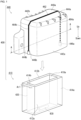
- FIG. 1 is a perspective view of the airbag module 400 according to Embodiment 1 of the present invention.
- FIG. 1 schematically illustrates a housing 410, an airbag cushion 420, and an inflator 430 of the airbag module 400.
- the airbag module 400 includes the housing 410.
- the folded or wound airbag cushion 420 is stowed inside the housing 410.
- the inflator 430 is installed in the airbag cushion 420.
- the cross-section of the housing 410 is a quadrangular shape and the upper part is an opening 410a.
- the airbag cushion 420 expands and deploys, of the four side surfaces 412a, 412b, 414a, and 414b of the housing 410, the first pair of side surfaces 412a, 412b facing each other expand so as to be separated from each other in the Ar1 direction, deforming the housing 410.
- the opening 410a on the upper side of the housing 410 opens up.
- the airbag cushion 420 expands, the airbag cushion 420 can be easily deployed to the outside through the opening 410a of the housing 410.
- the housing 410 opening readily provides an improvement in cushion resistance, reducing internal pressure during deployment of the airbag cushion 420. Therefore, the amount of cushion base material is anticipated to be reduced and the plate thickness of the housing 410 is anticipated to be reduced, enabling potential cost reduction.
- FIG. 1 illustrates the housing 410 having a quadrangular shape in cross-section view, but the present invention is not limited to this. Even if the housing 410 has a convex polygonal shape other than a quadrangular shape, the same effect as described above can be obtained.
- the airbag module 400 of Embodiment 1 further includes a cover 440 that covers the opening 410a and the four side surfaces 412a, 412b, 414a, and 414b of the housing 410.
- the cover 440 has an upper surface portion 440a covering the opening 410a of the housing 410 and four opposing surfaces 442a, 442b, 444a, 444b that oppose the four side surfaces 412a, 412b, 414a, 414b of the housing 410.
- the cover 440 is formed with a first weak portion 462 and second weak portions 464a and 464b.
- the first weak portion 462 is formed in the upper surface portion 440a, which is a portion of the cover 440 that covers the opening 410a of the housing 410, and extends in the longitudinal direction of the upper surface portion 440a.
- the first weak portion 462 is weaker than the area surrounding thereof and is cleaved by the separation of the first pair of side surfaces 412a and 412b.
- the second weak portions 464a and 464b are formed on the opposing surfaces 444a and 444b, which are the portions of the cover 440 that cover the mutually opposed second pair of side surfaces 414a and 414b of the housing 410, and continuously extend lower respectively from both ends of the first weak portion 462.
- the second weak portions 464a and 464b are weaker than the area surrounding thereof, and cleave following the cleavage of the first weak portion 462.
- the cover 440 with a first weak portion 462 as described above enables the cover 440 to cleave at the first weak portion 462 when the airbag cushion 420 expands and deploys. Therefore, the airbag cushion 420 can efficiently be expanded and deployed to the outside from the first weak portion 462 that has been cleaved. As a result, the airbag cushion 420 can be expanded and deployed more quickly and reliably than when a cover having no weak portion is used.
- the cover 440 is provided with the second weak portions 464a and 464b.
- the cover 440 also cleaves at the second weak portions 464a and 464b when the airbag cushion 420 expands and deploys. Therefore, the opening of the cover 440 when the airbag cushion 420 expands and deploys can be opened wider. Therefore, the airbag cushion 420 can be expanded and deployed to the outside more quickly and reliably.
- the direction in cross-section view of the second pair of side surfaces 414a and 414b extending in the longitudinal direction intersects with the direction in cross-section view of the first pair of side surfaces 412a and 412b extending in the longitudinal direction.
- FIG. 2 is a schematic cross-sectional view taken along the line A-A of the cover 440 of FIG. 1 .
- the cover 440 is provided with hinges 446a and 446b on the opposing surfaces 444a and 444b that are opposite the second pair of side surfaces 414a and 414b.
- straps 450a and 450b are engaged with hooks 448a and 448b and hooks 448c and 448d securing the hinges 446a and 446b to the opposing surfaces 444a and 444b.
- FIG. 3 is a diagram describing Embodiment 2 of the cover.
- the first weak portion 462 was formed on the upper surface portion 440a
- the second weak portions 464a and 464b were formed on the pair of opposing surfaces 444a and 444b.
- third weak portions 466a and 466b are formed in addition to the first weak portion 462 and second weak portions 464a and 464b.
- the third weak portions 466a and 466b are the portions that cover the opening 410a of the housing 410 (see FIG. 1 ) that extend along the boundaries of the upper surface portion 440a and the opposing surfaces 444a and 444b that are the portions that cover the second pair of side surfaces 414a and 414b of the housing 410 (see FIG. 1 ).
- the third weak portions 466a and 466b are weaker than the areas surrounding thereof and cleave subsequent to cleaving of the first weak portion 462.
- the cover 540 is cleaved at the third weak portions 466a and 466b in addition to the first weak portion 462 and the second weak portions 464a and 464b when the airbag cushion 420 expands and deploys.
- the opening of the cover 540 can be further widened, and the airbag cushion 420 can be expanded and deployed more quickly.
- FIG. 4 is a diagram describing Embodiment 3 of the cover which is not part of the present invention.
- the cover 440 of Embodiment 1 the first weak portion 462 was formed on the upper surface portion 440a, and the second weak portions 464a and 464b were formed on the pair of opposing surfaces 444a and 444b.
- the cover 640 illustrated in FIG. 4 only the first weak portion 462 is formed.
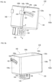
- FIG. 5 is a perspective view illustrating a first housing structure 110.
- FIG. 5(a) is an overall perspective view of the first housing structure 110.
- FIG. 5(b) is a perspective view of the first housing structure 110 of FIG. 5(a) observed from a different direction.
- FIG. 6 is a schematic cross-sectional view of the leg part of FIG. 5(a) taken along the line A-A.
- FIG. 6 illustrates an airbag cushion 420 and an inflator 430 not shown in FIG. 5(a) as dashed lines.
- the first housing structure 110 is quadrangular and has a first member 130 and a second member 140.
- the first member 130 has three side walls 130a, 130b, and 130c.
- the second member 140 includes three side walls 140a, 140b, and 140c that are opposite the first member 130 and overlap inside the first member 130.
- leg parts 134 and 144 extend from bottom walls 132 and 142 of the first member 130 and the second member 140 respectively.
- the first housing structure 110 is secured with the leg parts 134 and 144 to the frame 106 by a bolt 152 and a nut 154.
- the bolt 152 connects the first member 130 and the second member 140, and serves as a rotation axis for relative rotation thereof.
- the housing 110 is provided with a pin 162 and a bracket 164 as a member for guiding the rotation of the first member 130 and the second member 140.
- the pin 162 is secured to the first member 130.
- the bracket 164 is arc-shaped and is secured to the second member 140.
- An arc-shaped slot 164a in which the pin 162 is slidably inserted is formed in the bracket 164.
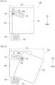
- FIG. 7 is a diagram describing the behavior of the first housing structure 110 of FIG. 5 during expansion and deployment of the airbag cushion 420.
- the pin 162 Prior to expansion and deployment of the airbag cushion 420, the pin 162 is positioned at start point P1 of the bracket 164 slot 164a as illustrated in FIG. 7(a) .
- the first member 130 is pushed out by the pressure thereof.
- the pin 162 moves in the slot 164a of the bracket 164 and the first member 130 rotates relative to the second member 140 around a rotational axis (bolt 152).
- the pin 162 moves to the end point P2 of the slot 164a and the opening 121 of the upper side of the case type first housing structure 110 opens up.
- rotation of the first member 130 with respect to the second member 140 causes the opening on the upper part of the first housing structure 110 to open up.
- the opening of the first housing structure 110 readily opens during expansion and deployment of the airbag cushion 420.
- speed of the airbag cushion deployment can be increased.
- the pin 162 and the bracket 164 are provided to enable guiding the rotation of the first member 130 relative to the second member 140 in the first housing structure 110.
- stable operation is feasible and the desired behavior can be reliably obtained.
- the first housing structure 110 includes bearings 166 that are connected to the bolt 152 as a rotation axis. Therefore, friction of the bolt 152 when the first member 130 rotates relative to the second member 140 can be reduced. Therefore, since the first member 130 and the second member 140 rotate more smoothly, the effects described above can be improved.
- FIG. 8 is a perspective view describing a second housing structure 210.
- the housing structure 210 includes four side walls, a side wall 212, side wall 214, side wall 216, and side wall 218, with the upper part thereof being an opening 210a, and two extendable walls 220a and 220b.
- the two extendable walls 220a and 220b connect one side wall 212 to two side walls 214 and 218 located on both sides thereof.
- the two extendable walls 220a and 220b are in a folded state before the airbag cushion 420 (see FIG. 1 ) expands and deploys.
- FIG. 9 is a perspective view illustrating a state in which the extendable walls 220a and 220b of the housing structure 210 of FIG. 8 are opened up. As illustrated in FIG. 9 , the two extendable walls 220a and 220b open up in this manner when the airbag cushion 420 (see FIG. 1 ) expands and deploys. Thus, the opening 210a of the upper part of the four side walls 212, 214, 216, and 218 opens up.
- the opening 210a of the housing structure 210 more readily opens when the airbag cushion 420 expands and deploys.
- the deployment speed of the airbag cushion 420 can be increased, and deployment behavior is stabilized. Therefore, since the occupant can be restrained more quickly, the occupant injury value can be reduced.
- the two extendable walls 220a and 220b have a triangular shape. Since the two extendable walls 220a and 220b have symmetrical shapes, the extendable wall 220a will be used as representative of the walls and will be described in detail below.
- the extendable wall 220a has a first side 226 along the edge of the side wall 212, a second side 224 along the edge of the side wall 214, and a third side 222 that connects the upper ends of the first side 226 and second side 224, composing a triangular shape.
- the two extendable walls 220a and 220b have a triangular shape with a width that increases toward the top.
- the opening 210a of the housing structure 210 widens toward the top. This enables further increase in the deployment speed of the airbag cushion 420.
- FIG. 10 is a perspective view illustrating a third housing structure 310.
- FIG. 10(a) is an overall perspective view of the third housing structure 310.
- FIG. 10(b) is a perspective view of the third housing structure 310 of FIG. 10(a) observed from a different direction.
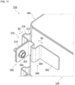
- FIG. 11 is an expanded perspective view of the vicinity of a connecting member 350 in FIG. 10(a) .
- the third housing structure 310 includes a first member 330 and a second member 340.
- the first member 330 has three side walls 330a, 330b, and 330c.
- the second member 340 has three side walls 340a, 340b, and 340c, and is arranged inside the first member 330.
- the first member 330 and second member 340 are connected by the connecting member 350.
- the connecting member 350 includes a first connecting member 360 and a second connecting member 370.
- the first connecting member 360 includes a joint part 362, a connecting part 364, and a bending part 366.
- the joint part 362 is the location for joining with the first member 330 and the connecting part 364 is the location for connecting to the second connecting member 370.
- the bending part 366 that is a bending location is formed between the joint part 362 and the connecting part 364.
- the second connecting member 370 includes a joint part 372, a connecting part 374, and a bending part 376.
- the joint part 372 is the location for joining with the second member 340 and the connecting part 374 is the location for connecting to the first connecting member 360.
- a bending part 376 that is the bending portion that is separated from the first member or the second member is formed between the joint part 372 and the connecting part 374.
- the connecting portion 364 of the first connecting member 360 and connecting portion 374 of the second connecting member 370 are secured by a bolt 352 illustrated in FIG. 10(a) and a nut 354 illustrated in FIG. 10(b) .
- the first member 330 and second member 340 are connected by means of the first connecting member 360 and second connecting member 370.
- the pressure thereof causes the bending parts 366 and 376 that are the bent portions of the connecting member 350 to extend in the directions of the arrows D2 and D3 illustrated in FIG. 11 .
- the first member 330 separates from the second member 340 in the direction of the arrow D1 illustrated in FIG. 10(a) causing an opening 310a (see FIG. 10(b) ) of the upper part of the third housing structure 310 to open.
- first connecting member 360 and second connecting member 370 a configuration using two connecting members (first connecting member 360 and second connecting member 370) was illustrated but the configuration is not limited to this.
- the connecting part 364 of the first connecting member 360 is connected to the second member 340, the effect described above can be achieved without requiring the second connecting member 370.
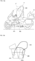
- FIG. 12 is a diagram illustrating a vehicle equipped with the airbag module of the present embodiment.
- FIG. 12(a) illustrates an example of a motorcycle 10 as a vehicle, and the airbag module 400 of Embodiment 1 as an airbag module mounted on the motorcycle 10.
- the vehicle is not limited to the motorcycle as a matter of course, and may be a four-wheeled vehicle, and the airbag module to be mounted may also use the airbag module of another embodiment.
- the airbag module 400 is mounted on the front portion of the motorcycle 10, that is, in front of the occupant P.
- the folded or rolled airbag cushion 420 and equipped inflator 430 are stowed inside the housing 410 of the airbag module 400 (see FIG. 1 ).
- FIG. 12(b) is a schematic diagram illustrating the behavior of the airbag module 400 of FIG. 12(a) during expansion and deployment.
- the occupant P is in a forward leaning posture as illustrated in the position P'.
- the housing 410 is cleaved at the first weak portion 462 and the second weak portions 464a and 464b (see FIG. 1 ).
- the airbag cushion 420 expands and deploys to the outside of the housing 410, and as illustrated in FIG. 12(a) , the occupant P can therefore be restrained and protected.
- the present invention can be used as an airbag module provided with an airbag cushion and a case type housing for stowing the airbag cushion.
- Second housing structure 210. Opening, 212. Side wall, 214. Side wall, 216. Side wall, 218. Side wall, 220a. Extendable wall, 220b. Extendable wall, 222. Third side, 224.
Landscapes
- Engineering & Computer Science (AREA)
- Mechanical Engineering (AREA)
- Air Bags (AREA)
Claims (4)
- Airbagmodul (400), umfassend:ein gefaltetes oder gerolltes Airbagkissen (420),einen Gasgenerator (430), der in dem Airbagkissen (420) eingerichtet ist, undein Gehäuse (110; 210; 310; 410) zum Verstauen dieses Airbagkissens (420), wobeidas Gehäuse (110; 210; 310; 410) eine konvexe polygonale Form im Querschnitt aufweist, mindestens ein erstes Paar einander gegenüberliegender Seitenoberflächen umfasst, und eine Öffnung (121; 210a; 310a; 410a) auf der Oberseite aufweist, und wenn sich das Airbagkissen (420) ausdehnt und entfaltet, das erste Paar einander gegenüberliegender Seitenoberflächen angeordnet ist, um sich auszudehnen, um sich voneinander zu trennen,das Airbagmodul (400) ferner eine Abdeckung (440; 540), die die Öffnung (121; 210a; 310a; 410a) und Seitenoberflächen des Gehäuses (110; 210; 310; 410) abdeckt, umfasst,wobei die Abdeckung (440; 540) die einen oberen Oberflächenabschnitt (440a) einschließt, der die Öffnung (121; 210a; 310a; 410a) des Gehäuses (110; 210; 310; 410) abdeckt, mit einem ersten schwachen Abschnitt (462) ausgebildet ist, der sich in der Längsrichtung des oberen Oberflächenabschnitts (440a) erstreckt, der schwächer als der umgebende Bereich hiervon ist, und der angeordnet ist, um durch die Trennung des ersten Paars Seitenoberflächen gespalten wird, wenn sich das Airbagkissen (420) ausdehnt und entfaltet,die Abdeckung (440; 540) ferner einen Abschnitt einschließt, der ein zweites Paar einander gegenüberliegender Seitenoberflächen des Gehäuses (110; 210; 310; 410) abdeckt, und mit zweiten schwachen Abschnitten (464a, 464b) ausgebildet ist, die sich jeweils durchgehend von einem unteren Teil beider Enden des ersten schwachen Abschnitts (462) erstrecken, die schwächer als die umgebenden Bereiche davon sind, und die angeordnet sind, um im Anschluss an das Spalten des ersten schwachen Abschnitts (462) gespalten zu werden, unddas Gehäuse (110; 210; 310; 410) und die Abdeckung (440; 540) sind jeweils angeordnet sind, um sich in Bezug auf die Längsachse drehend öffnen, um das Airbagkissen (420) zu entfalten.
- Airbagmodul (400) nach Anspruch 1, wobei die konvexe polygonale Form eine viereckige Form ist.
- Airbagmodul (400) nach Anspruch 2, wobei sich die Richtung im Querschnitt des zweiten Paars Seitenoberflächen, die sich in Längsrichtung erstrecken, mit der Richtung im Querschnitt des ersten Paars Seitenoberflächen, die sich in Längsrichtung erstrecken, schneidet.
- Airbagmodul (400) nach Anspruch 1 oder 3, wobei die Abdeckung (440; 540) einen dritten schwachen Abschnitt einschließt, der sich entlang der Grenze des Abschnitts erstreckt, der die Öffnung (121; 210a; 310a; 410a) des Gehäuses (110; 210; 310; 410) abdeckt, und wobei der Abschnitt, der das zweite Paar Seitenoberflächen des Gehäuses (110; 210; 310; 410) abdeckt, schwächer als der umgebende Bereich davon ist, und sich im Anschluss an das Spalten des ersten schwachen Abschnitts (462) spaltet.
Applications Claiming Priority (2)
| Application Number | Priority Date | Filing Date | Title |
|---|---|---|---|
| JP2019228075 | 2019-12-18 | ||
| PCT/JP2020/039570 WO2021124674A1 (ja) | 2019-12-18 | 2020-10-21 | エアバッグモジュール |
Publications (3)
| Publication Number | Publication Date |
|---|---|
| EP4079583A1 EP4079583A1 (de) | 2022-10-26 |
| EP4079583A4 EP4079583A4 (de) | 2023-12-27 |
| EP4079583B1 true EP4079583B1 (de) | 2025-05-14 |
Family
ID=76477189
Family Applications (1)
| Application Number | Title | Priority Date | Filing Date |
|---|---|---|---|
| EP20900883.8A Active EP4079583B1 (de) | 2019-12-18 | 2020-10-21 | Airbagmodul |
Country Status (6)
| Country | Link |
|---|---|
| US (1) | US11904970B2 (de) |
| EP (1) | EP4079583B1 (de) |
| JP (1) | JP7254213B2 (de) |
| KR (1) | KR102725182B1 (de) |
| CN (1) | CN114728680A (de) |
| WO (1) | WO2021124674A1 (de) |
Families Citing this family (2)
| Publication number | Priority date | Publication date | Assignee | Title |
|---|---|---|---|---|
| CN114390986B (zh) * | 2019-10-01 | 2023-11-14 | 奥托立夫开发公司 | 安全气囊模块 |
| US11787362B2 (en) * | 2019-11-25 | 2023-10-17 | Autoliv Development Ab | Airbag module |
Family Cites Families (32)
| Publication number | Priority date | Publication date | Assignee | Title |
|---|---|---|---|---|
| US4903986A (en) * | 1988-11-14 | 1990-02-27 | General Motors Corporation | Modular occupant restraint system |
| US5308111A (en) * | 1993-01-29 | 1994-05-03 | General Motors Corporation | Inflatable restraint having an improved tether |
| DE29721644U1 (de) * | 1997-12-08 | 1998-04-02 | Trw Occupant Restraint Systems Gmbh, 73551 Alfdorf | Gassack-Modul für ein Fahrzeuginsassen-Rückhaltesystem |
| DE29721643U1 (de) * | 1997-12-08 | 1998-04-02 | Trw Occupant Restraint Systems Gmbh, 73551 Alfdorf | Gassack-Modul für ein Fahrzeuginsassen-Rückhaltesystem |
| DE29806083U1 (de) * | 1998-04-02 | 1998-07-30 | TRW Occupant Restraint Systems GmbH & Co. KG, 73553 Alfdorf | Gassack-Modul für ein Fahrzeuginsassen-Rückhaltesystem |
| JP4016083B2 (ja) | 1998-11-18 | 2007-12-05 | カルソニックカンセイ株式会社 | 車両用エアバッグ構造 |
| JP2000153745A (ja) | 1998-11-20 | 2000-06-06 | Kansei Corp | 車両用エアバッグ装置 |
| JP2001010438A (ja) | 1999-06-24 | 2001-01-16 | T S Tec Kk | サイドエアーバッグ装置装備シート |
| ES2215808T3 (es) * | 2000-04-28 | 2004-10-16 | Inoac Corporation | Estructura rompible de un panel de airbag. |
| DE10136893B4 (de) * | 2001-07-25 | 2006-02-09 | Takata-Petri Ag | Airbagmodul |
| US6848705B2 (en) * | 2002-03-20 | 2005-02-01 | Autoliv Asp, Inc. | Airbag cover with multi-axis deployment |
| US6793238B2 (en) * | 2002-03-20 | 2004-09-21 | Autoliv Asp, Inc. | Airbag covers for multi-axis deployment |
| US7104566B2 (en) * | 2002-04-25 | 2006-09-12 | Delphi Technologies, Inc. | Airbag module and cover arrangement |
| US7216892B2 (en) * | 2004-08-20 | 2007-05-15 | Key Safety Systems, Inc. | Air bag door and attachment method |
| JP4907184B2 (ja) | 2006-02-02 | 2012-03-28 | タカタ株式会社 | エアバッグ装置 |
| JP2007203937A (ja) | 2006-02-03 | 2007-08-16 | Toyoda Gosei Co Ltd | 膝保護用エアバッグ装置 |
| JP2009029167A (ja) | 2007-07-24 | 2009-02-12 | Autoliv Development Ab | エアバッグ用ハウジング |
| JP5333057B2 (ja) * | 2008-11-12 | 2013-11-06 | 豊田合成株式会社 | 助手席用エアバッグ装置 |
| JP5479359B2 (ja) | 2008-11-14 | 2014-04-23 | オートリブ ディベロップメント エービー | エアバッグ装置 |
| JP2011000962A (ja) * | 2009-06-18 | 2011-01-06 | Honda Motor Co Ltd | 鞍乗型車両のエアバッグ装置 |
| JP5564516B2 (ja) * | 2009-12-25 | 2014-07-30 | オートリブ ディベロップメント エービー | エアバッグ装置 |
| JP5604353B2 (ja) * | 2011-03-31 | 2014-10-08 | タカタ株式会社 | エアバッグ装置及びエアバッグカバー |
| DE102013009065A1 (de) * | 2013-05-28 | 2014-12-04 | Autoliv Development Ab | Knieaufprallschutzeinrichtung für ein Kraftfahrzeug |
| CN105324277B (zh) | 2013-05-31 | 2017-05-31 | 奥托立夫开发公司 | 安全气囊装置 |
| JP6206310B2 (ja) | 2014-04-18 | 2017-10-04 | 豊田合成株式会社 | 乗物用シートのシートバック |
| DE102017120770A1 (de) * | 2017-09-08 | 2019-03-14 | Trw Automotive Safety Systems Gmbh | Lenkradairbagmodul, lenkradinformationsmodul, lenkrad sowie verfahren zum entfalten eines gassacks |
| US10688954B2 (en) | 2017-11-29 | 2020-06-23 | GM Global Technology Operations LLC | Airbag assembly with tethered reaction surface and cushion configured to permit forward head rotation |
| CN208325072U (zh) | 2018-06-06 | 2019-01-04 | 深圳市麦思美科技有限公司 | 一种可伸缩的车载蓝光播放器 |
| DE202019103552U1 (de) * | 2019-06-27 | 2020-10-08 | ZF Automotive Safety Germany GmbH | Fahrergassackmodul sowie Lenkvorrichtung mit einem solchen Fahrergassackmodul |
| US11447089B2 (en) * | 2019-08-23 | 2022-09-20 | Toyoda Gosei Co., Ltd. | Airbag assembly with reaction surface |
| CN114390986B (zh) * | 2019-10-01 | 2023-11-14 | 奥托立夫开发公司 | 安全气囊模块 |
| US11787362B2 (en) * | 2019-11-25 | 2023-10-17 | Autoliv Development Ab | Airbag module |
-
2020
- 2020-10-21 US US17/757,269 patent/US11904970B2/en active Active
- 2020-10-21 CN CN202080079699.9A patent/CN114728680A/zh active Pending
- 2020-10-21 WO PCT/JP2020/039570 patent/WO2021124674A1/ja not_active Ceased
- 2020-10-21 JP JP2021565343A patent/JP7254213B2/ja active Active
- 2020-10-21 EP EP20900883.8A patent/EP4079583B1/de active Active
- 2020-10-21 KR KR1020227024060A patent/KR102725182B1/ko active Active
Also Published As
| Publication number | Publication date |
|---|---|
| EP4079583A4 (de) | 2023-12-27 |
| JPWO2021124674A1 (de) | 2021-06-24 |
| WO2021124674A1 (ja) | 2021-06-24 |
| BR112022009585A2 (pt) | 2022-08-02 |
| KR20220109469A (ko) | 2022-08-04 |
| EP4079583A1 (de) | 2022-10-26 |
| CN114728680A (zh) | 2022-07-08 |
| JP7254213B2 (ja) | 2023-04-07 |
| US20230001998A1 (en) | 2023-01-05 |
| KR102725182B1 (ko) | 2024-11-01 |
| US11904970B2 (en) | 2024-02-20 |
Similar Documents
| Publication | Publication Date | Title |
|---|---|---|
| US6874810B2 (en) | Airbag cover deployment flaps | |
| EP3357765B1 (de) | Seitenairbagvorrichtung | |
| US10569732B2 (en) | Arm rest | |
| US10328886B2 (en) | Module cover, arrangement of a module cover between a vehicle roof and a vehicle ceiling, airbag module, and vehicle safety system | |
| CN102741092B (zh) | 副驾驶座用膝部安全气囊装置 | |
| EP2322390B1 (de) | Knie-airbagvorrichtung für ein fahrzeug | |
| EP1842741A2 (de) | Führungsplatte für seitlichen Airbag | |
| EP4032756B1 (de) | Fahrersitz-airbagvorrichtung | |
| US11745691B2 (en) | Device for coupling curtain airbag to vehicle body | |
| JP4907175B2 (ja) | 座席シート装置 | |
| US11904970B2 (en) | Airbag module | |
| EP2316696B1 (de) | Knie-airbagvorrichtung für ein fahrzeug | |
| US9333937B1 (en) | Airbag cover with stress relief features | |
| EP4043294B1 (de) | Airbagmodul | |
| EP4067175B1 (de) | Airbagmodul | |
| EP2072346A1 (de) | Optimiertes Airbagmodul | |
| US20070102971A1 (en) | Vehicle seat with articulating cushion component | |
| US11975658B2 (en) | Controlled detachment features of steering column mounted camera | |
| KR102505743B1 (ko) | 에어백 장치 | |
| US20070057498A1 (en) | Airbag device | |
| EP4442548A1 (de) | Airbagvorrichtung für ein fahrzeug | |
| EP2353948A1 (de) | Airbagvorrichtung | |
| KR101430194B1 (ko) | 차량의 운전석 에어백 모듈 | |
| BR112022009585B1 (pt) | Módulo de airbag | |
| EP4578745A1 (de) | Fussgängerschutz-airbagvorrichtung |
Legal Events
| Date | Code | Title | Description |
|---|---|---|---|
| STAA | Information on the status of an ep patent application or granted ep patent |
Free format text: STATUS: THE INTERNATIONAL PUBLICATION HAS BEEN MADE |
|
| PUAI | Public reference made under article 153(3) epc to a published international application that has entered the european phase |
Free format text: ORIGINAL CODE: 0009012 |
|
| STAA | Information on the status of an ep patent application or granted ep patent |
Free format text: STATUS: REQUEST FOR EXAMINATION WAS MADE |
|
| 17P | Request for examination filed |
Effective date: 20220705 |
|
| AK | Designated contracting states |
Kind code of ref document: A1 Designated state(s): AL AT BE BG CH CY CZ DE DK EE ES FI FR GB GR HR HU IE IS IT LI LT LU LV MC MK MT NL NO PL PT RO RS SE SI SK SM TR |
|
| DAV | Request for validation of the european patent (deleted) | ||
| DAX | Request for extension of the european patent (deleted) | ||
| A4 | Supplementary search report drawn up and despatched |
Effective date: 20231122 |
|
| RIC1 | Information provided on ipc code assigned before grant |
Ipc: B60R 21/216 20110101ALI20231117BHEP Ipc: B60R 21/217 20110101ALI20231117BHEP Ipc: B62J 27/20 20200101ALI20231117BHEP Ipc: B60R 21/215 20110101AFI20231117BHEP |
|
| GRAP | Despatch of communication of intention to grant a patent |
Free format text: ORIGINAL CODE: EPIDOSNIGR1 |
|
| STAA | Information on the status of an ep patent application or granted ep patent |
Free format text: STATUS: GRANT OF PATENT IS INTENDED |
|
| GRAJ | Information related to disapproval of communication of intention to grant by the applicant or resumption of examination proceedings by the epo deleted |
Free format text: ORIGINAL CODE: EPIDOSDIGR1 |
|
| STAA | Information on the status of an ep patent application or granted ep patent |
Free format text: STATUS: REQUEST FOR EXAMINATION WAS MADE |
|
| RIC1 | Information provided on ipc code assigned before grant |
Ipc: B60R 21/216 20110101ALI20250123BHEP Ipc: B60R 21/217 20110101ALI20250123BHEP Ipc: B62J 27/20 20200101ALI20250123BHEP Ipc: B60R 21/215 20110101AFI20250123BHEP |
|
| INTG | Intention to grant announced |
Effective date: 20250207 |
|
| INTC | Intention to grant announced (deleted) | ||
| GRAP | Despatch of communication of intention to grant a patent |
Free format text: ORIGINAL CODE: EPIDOSNIGR1 |
|
| STAA | Information on the status of an ep patent application or granted ep patent |
Free format text: STATUS: GRANT OF PATENT IS INTENDED |
|
| GRAS | Grant fee paid |
Free format text: ORIGINAL CODE: EPIDOSNIGR3 |
|
| GRAA | (expected) grant |
Free format text: ORIGINAL CODE: 0009210 |
|
| STAA | Information on the status of an ep patent application or granted ep patent |
Free format text: STATUS: THE PATENT HAS BEEN GRANTED |
|
| INTG | Intention to grant announced |
Effective date: 20250326 |
|
| AK | Designated contracting states |
Kind code of ref document: B1 Designated state(s): AL AT BE BG CH CY CZ DE DK EE ES FI FR GB GR HR HU IE IS IT LI LT LU LV MC MK MT NL NO PL PT RO RS SE SI SK SM TR |
|
| REG | Reference to a national code |
Ref country code: GB Ref legal event code: FG4D |
|
| REG | Reference to a national code |
Ref country code: CH Ref legal event code: EP |
|
| REG | Reference to a national code |
Ref country code: IE Ref legal event code: FG4D |
|
| REG | Reference to a national code |
Ref country code: DE Ref legal event code: R096 Ref document number: 602020051429 Country of ref document: DE |
|
| REG | Reference to a national code |
Ref country code: NL Ref legal event code: MP Effective date: 20250514 |
|
| PG25 | Lapsed in a contracting state [announced via postgrant information from national office to epo] |
Ref country code: FI Free format text: LAPSE BECAUSE OF FAILURE TO SUBMIT A TRANSLATION OF THE DESCRIPTION OR TO PAY THE FEE WITHIN THE PRESCRIBED TIME-LIMIT Effective date: 20250514 Ref country code: ES Free format text: LAPSE BECAUSE OF FAILURE TO SUBMIT A TRANSLATION OF THE DESCRIPTION OR TO PAY THE FEE WITHIN THE PRESCRIBED TIME-LIMIT Effective date: 20250514 Ref country code: PT Free format text: LAPSE BECAUSE OF FAILURE TO SUBMIT A TRANSLATION OF THE DESCRIPTION OR TO PAY THE FEE WITHIN THE PRESCRIBED TIME-LIMIT Effective date: 20250915 |
|
| REG | Reference to a national code |
Ref country code: LT Ref legal event code: MG9D |
|
| PG25 | Lapsed in a contracting state [announced via postgrant information from national office to epo] |
Ref country code: NO Free format text: LAPSE BECAUSE OF FAILURE TO SUBMIT A TRANSLATION OF THE DESCRIPTION OR TO PAY THE FEE WITHIN THE PRESCRIBED TIME-LIMIT Effective date: 20250814 Ref country code: GR Free format text: LAPSE BECAUSE OF FAILURE TO SUBMIT A TRANSLATION OF THE DESCRIPTION OR TO PAY THE FEE WITHIN THE PRESCRIBED TIME-LIMIT Effective date: 20250815 |
|
| PG25 | Lapsed in a contracting state [announced via postgrant information from national office to epo] |
Ref country code: PL Free format text: LAPSE BECAUSE OF FAILURE TO SUBMIT A TRANSLATION OF THE DESCRIPTION OR TO PAY THE FEE WITHIN THE PRESCRIBED TIME-LIMIT Effective date: 20250514 Ref country code: NL Free format text: LAPSE BECAUSE OF FAILURE TO SUBMIT A TRANSLATION OF THE DESCRIPTION OR TO PAY THE FEE WITHIN THE PRESCRIBED TIME-LIMIT Effective date: 20250514 |
|
| REG | Reference to a national code |
Ref country code: AT Ref legal event code: MK05 Ref document number: 1794543 Country of ref document: AT Kind code of ref document: T Effective date: 20250514 |
|
| PG25 | Lapsed in a contracting state [announced via postgrant information from national office to epo] |
Ref country code: BG Free format text: LAPSE BECAUSE OF FAILURE TO SUBMIT A TRANSLATION OF THE DESCRIPTION OR TO PAY THE FEE WITHIN THE PRESCRIBED TIME-LIMIT Effective date: 20250514 |
|
| PG25 | Lapsed in a contracting state [announced via postgrant information from national office to epo] |
Ref country code: HR Free format text: LAPSE BECAUSE OF FAILURE TO SUBMIT A TRANSLATION OF THE DESCRIPTION OR TO PAY THE FEE WITHIN THE PRESCRIBED TIME-LIMIT Effective date: 20250514 |
|
| PG25 | Lapsed in a contracting state [announced via postgrant information from national office to epo] |
Ref country code: AT Free format text: LAPSE BECAUSE OF FAILURE TO SUBMIT A TRANSLATION OF THE DESCRIPTION OR TO PAY THE FEE WITHIN THE PRESCRIBED TIME-LIMIT Effective date: 20250514 |
|
| PG25 | Lapsed in a contracting state [announced via postgrant information from national office to epo] |
Ref country code: RS Free format text: LAPSE BECAUSE OF FAILURE TO SUBMIT A TRANSLATION OF THE DESCRIPTION OR TO PAY THE FEE WITHIN THE PRESCRIBED TIME-LIMIT Effective date: 20250814 |
|
| PG25 | Lapsed in a contracting state [announced via postgrant information from national office to epo] |
Ref country code: IS Free format text: LAPSE BECAUSE OF FAILURE TO SUBMIT A TRANSLATION OF THE DESCRIPTION OR TO PAY THE FEE WITHIN THE PRESCRIBED TIME-LIMIT Effective date: 20250914 |
|
| PG25 | Lapsed in a contracting state [announced via postgrant information from national office to epo] |
Ref country code: LV Free format text: LAPSE BECAUSE OF FAILURE TO SUBMIT A TRANSLATION OF THE DESCRIPTION OR TO PAY THE FEE WITHIN THE PRESCRIBED TIME-LIMIT Effective date: 20250514 |
|
| PGFP | Annual fee paid to national office [announced via postgrant information from national office to epo] |
Ref country code: DE Payment date: 20251028 Year of fee payment: 6 |
|
| PGFP | Annual fee paid to national office [announced via postgrant information from national office to epo] |
Ref country code: GB Payment date: 20251023 Year of fee payment: 6 |
|
| PG25 | Lapsed in a contracting state [announced via postgrant information from national office to epo] |
Ref country code: SM Free format text: LAPSE BECAUSE OF FAILURE TO SUBMIT A TRANSLATION OF THE DESCRIPTION OR TO PAY THE FEE WITHIN THE PRESCRIBED TIME-LIMIT Effective date: 20250514 Ref country code: DK Free format text: LAPSE BECAUSE OF FAILURE TO SUBMIT A TRANSLATION OF THE DESCRIPTION OR TO PAY THE FEE WITHIN THE PRESCRIBED TIME-LIMIT Effective date: 20250514 |
|
| PGFP | Annual fee paid to national office [announced via postgrant information from national office to epo] |
Ref country code: FR Payment date: 20251027 Year of fee payment: 6 |
|
| PG25 | Lapsed in a contracting state [announced via postgrant information from national office to epo] |
Ref country code: CZ Free format text: LAPSE BECAUSE OF FAILURE TO SUBMIT A TRANSLATION OF THE DESCRIPTION OR TO PAY THE FEE WITHIN THE PRESCRIBED TIME-LIMIT Effective date: 20250514 |
|
| PG25 | Lapsed in a contracting state [announced via postgrant information from national office to epo] |
Ref country code: EE Free format text: LAPSE BECAUSE OF FAILURE TO SUBMIT A TRANSLATION OF THE DESCRIPTION OR TO PAY THE FEE WITHIN THE PRESCRIBED TIME-LIMIT Effective date: 20250514 |
|
| PG25 | Lapsed in a contracting state [announced via postgrant information from national office to epo] |
Ref country code: SK Free format text: LAPSE BECAUSE OF FAILURE TO SUBMIT A TRANSLATION OF THE DESCRIPTION OR TO PAY THE FEE WITHIN THE PRESCRIBED TIME-LIMIT Effective date: 20250514 |
|
| PG25 | Lapsed in a contracting state [announced via postgrant information from national office to epo] |
Ref country code: IT Free format text: LAPSE BECAUSE OF FAILURE TO SUBMIT A TRANSLATION OF THE DESCRIPTION OR TO PAY THE FEE WITHIN THE PRESCRIBED TIME-LIMIT Effective date: 20250514 |
|
| PG25 | Lapsed in a contracting state [announced via postgrant information from national office to epo] |
Ref country code: RO Free format text: LAPSE BECAUSE OF FAILURE TO SUBMIT A TRANSLATION OF THE DESCRIPTION OR TO PAY THE FEE WITHIN THE PRESCRIBED TIME-LIMIT Effective date: 20250514 |
|
| REG | Reference to a national code |
Ref country code: DE Ref legal event code: R097 Ref document number: 602020051429 Country of ref document: DE |
|
| PLBE | No opposition filed within time limit |
Free format text: ORIGINAL CODE: 0009261 |
|
| STAA | Information on the status of an ep patent application or granted ep patent |
Free format text: STATUS: NO OPPOSITION FILED WITHIN TIME LIMIT |
|
| REG | Reference to a national code |
Ref country code: CH Ref legal event code: L10 Free format text: ST27 STATUS EVENT CODE: U-0-0-L10-L00 (AS PROVIDED BY THE NATIONAL OFFICE) Effective date: 20260325 |
|
| 26N | No opposition filed |
Effective date: 20260217 |