EP4079937A2 - Vorrichtung zur herstellung von wasserstoff durch wasserelektrolyse - Google Patents
Vorrichtung zur herstellung von wasserstoff durch wasserelektrolyse Download PDFInfo
- Publication number
- EP4079937A2 EP4079937A2 EP22157374.4A EP22157374A EP4079937A2 EP 4079937 A2 EP4079937 A2 EP 4079937A2 EP 22157374 A EP22157374 A EP 22157374A EP 4079937 A2 EP4079937 A2 EP 4079937A2
- Authority
- EP
- European Patent Office
- Prior art keywords
- protective shell
- water electrolysis
- producing hydrogen
- electrolytic bath
- electrolysis according
- Prior art date
- Legal status (The legal status is an assumption and is not a legal conclusion. Google has not performed a legal analysis and makes no representation as to the accuracy of the status listed.)
- Withdrawn
Links
Images


Classifications
-
- C—CHEMISTRY; METALLURGY
- C25—ELECTROLYTIC OR ELECTROPHORETIC PROCESSES; APPARATUS THEREFOR
- C25B—ELECTROLYTIC OR ELECTROPHORETIC PROCESSES FOR THE PRODUCTION OF COMPOUNDS OR NON-METALS; APPARATUS THEREFOR
- C25B1/00—Electrolytic production of inorganic compounds or non-metals
- C25B1/01—Products
- C25B1/02—Hydrogen or oxygen
- C25B1/04—Hydrogen or oxygen by electrolysis of water
-
- C—CHEMISTRY; METALLURGY
- C25—ELECTROLYTIC OR ELECTROPHORETIC PROCESSES; APPARATUS THEREFOR
- C25B—ELECTROLYTIC OR ELECTROPHORETIC PROCESSES FOR THE PRODUCTION OF COMPOUNDS OR NON-METALS; APPARATUS THEREFOR
- C25B15/00—Operating or servicing cells
- C25B15/08—Supplying or removing reactants or electrolytes; Regeneration of electrolytes
-
- C—CHEMISTRY; METALLURGY
- C25—ELECTROLYTIC OR ELECTROPHORETIC PROCESSES; APPARATUS THEREFOR
- C25B—ELECTROLYTIC OR ELECTROPHORETIC PROCESSES FOR THE PRODUCTION OF COMPOUNDS OR NON-METALS; APPARATUS THEREFOR
- C25B9/00—Cells or assemblies of cells; Constructional parts of cells; Assemblies of constructional parts, e.g. electrode-diaphragm assemblies; Process-related cell features
-
- C—CHEMISTRY; METALLURGY
- C25—ELECTROLYTIC OR ELECTROPHORETIC PROCESSES; APPARATUS THEREFOR
- C25B—ELECTROLYTIC OR ELECTROPHORETIC PROCESSES FOR THE PRODUCTION OF COMPOUNDS OR NON-METALS; APPARATUS THEREFOR
- C25B9/00—Cells or assemblies of cells; Constructional parts of cells; Assemblies of constructional parts, e.g. electrode-diaphragm assemblies; Process-related cell features
- C25B9/60—Constructional parts of cells
- C25B9/65—Means for supplying current; Electrode connections; Electric inter-cell connections
-
- C—CHEMISTRY; METALLURGY
- C25—ELECTROLYTIC OR ELECTROPHORETIC PROCESSES; APPARATUS THEREFOR
- C25B—ELECTROLYTIC OR ELECTROPHORETIC PROCESSES FOR THE PRODUCTION OF COMPOUNDS OR NON-METALS; APPARATUS THEREFOR
- C25B9/00—Cells or assemblies of cells; Constructional parts of cells; Assemblies of constructional parts, e.g. electrode-diaphragm assemblies; Process-related cell features
- C25B9/70—Assemblies comprising two or more cells
-
- C—CHEMISTRY; METALLURGY
- C25—ELECTROLYTIC OR ELECTROPHORETIC PROCESSES; APPARATUS THEREFOR
- C25B—ELECTROLYTIC OR ELECTROPHORETIC PROCESSES FOR THE PRODUCTION OF COMPOUNDS OR NON-METALS; APPARATUS THEREFOR
- C25B9/00—Cells or assemblies of cells; Constructional parts of cells; Assemblies of constructional parts, e.g. electrode-diaphragm assemblies; Process-related cell features
- C25B9/70—Assemblies comprising two or more cells
- C25B9/73—Assemblies comprising two or more cells of the filter-press type
-
- Y—GENERAL TAGGING OF NEW TECHNOLOGICAL DEVELOPMENTS; GENERAL TAGGING OF CROSS-SECTIONAL TECHNOLOGIES SPANNING OVER SEVERAL SECTIONS OF THE IPC; TECHNICAL SUBJECTS COVERED BY FORMER USPC CROSS-REFERENCE ART COLLECTIONS [XRACs] AND DIGESTS
- Y02—TECHNOLOGIES OR APPLICATIONS FOR MITIGATION OR ADAPTATION AGAINST CLIMATE CHANGE
- Y02E—REDUCTION OF GREENHOUSE GAS [GHG] EMISSIONS, RELATED TO ENERGY GENERATION, TRANSMISSION OR DISTRIBUTION
- Y02E60/00—Enabling technologies; Technologies with a potential or indirect contribution to GHG emissions mitigation
- Y02E60/30—Hydrogen technology
- Y02E60/36—Hydrogen production from non-carbon containing sources, e.g. by water electrolysis
Definitions
- the present disclosure relates to the technical field of hydrogen preparation, in particular to a device for producing hydrogen by water electrolysis.
- the electrolytic bath in the traditional device for producing hydrogen by water electrolysis is an exposed structure, and this type of electrolytic bath has the characteristics of low cost.
- the electrolytic bath body is charged, and the charged parts such as the electrode plate and the end clamp plate are exposed, thus there is a safety risk when the electrolytic bath is in an explosive gas environment.
- the device for producing hydrogen by water electrolysis is only suitable for indoor installation, and not suitable for outdoor installation, resulting in low versatility of the device for producing hydrogen by water electrolysis.
- the object of the present disclosure is to provide a device for producing hydrogen by water electrolysis, which improves the versatility of the device for producing hydrogen by water electrolysis.
- the present disclosure provides a device for producing hydrogen by water electrolysis, which includes a protective shell and an electrolytic bath provided in the protective shell, and the electrolytic bath is connected with a power supply cable and a pipeline, and both the power supply cable and the pipeline are coupled to the outside of the protective shell.
- the outer wall of the electrolytic bath is provided with a thermal insulation layer.
- the thermal insulation layer is sleeved on the outside of the electrolytic bath.
- a junction box is provided on the protective shell, and a connection terminal of the power supply cable is coupled to a connection terminal in the junction box, and the number of the junction box is one or at least two.
- the junction box is located on the elevation surface of the protective shell or the top surface of the protective shell or the bottom surface of the protective shell;
- the interface ends of the junction box and of the pipeline are located on the same wall surface or different wall surfaces of the protective shell.
- an electrolytic bath connection port coupled to the pipeline is provided on the protective shell.
- the electrolytic bath is a vertical electrolytic bath or a horizontal electrolytic bath.
- an access panel is provided on the protective shell, and a blocking unit capable of blocking the access panel is provided on the protective shell.
- the number of the electrolytic bath is one or more;
- the multiple electrolytic baths are coupled in parallel or in series, or the power supply cables of each electrolytic bath are independently provided.
- the protective shell has a closed structure.
- a sampling structure for sampling gas inside the protective shell is provided on the protective shell.
- the protective shell is filled with inert gas, and the internal air pressure of the protective shell is greater than the external air pressure of the protective shell.
- the inside of the protective shell is connected with the outside of the protective shell.
- a ventilation device is provided on the protective cell.
- a hydrogen amount detection device and an alarm device coupled to the hydrogen amount detection device are provided inside the protective shell.
- the device for producing hydrogen by water electrolysis includes a protective shell and an electrolytic bath provided in the protective shell, and the electrolytic bath is connected with a power supply cable and a pipeline, and both the power supply cable and the pipeline are coupled to the outside of the protective shell.
- a protective shell is provided outside the electrolytic bath to avoid the exposed design of the electrolytic bath, that is, the device for producing hydrogen by water electrolysis can thus be installed indoors or outdoors, thereby improving the versatility of the device for producing hydrogen by water electrolysis.
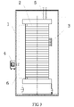
- Figures 1-5 1-protective shell, 2-electrolytic bath, 3-thermal insulation layer, 4-junction box, 5-pipeline, 6-power supply cable, 7-hydrogen detection alarm, 8-a ventilation device, 9-sampling structure.
- the core of the present disclosure is to provide a device for producing hydrogen by water electrolysis, wherein the versatility of the device for producing hydrogen by water electrolysis is improved.
- the device for producing hydrogen by water electrolysis comprises a protective shell 1 and an electrolytic bath 2 provided in the protective shell 1.
- the electrolytic bath 2 may be an electrolytic bath for producing hydrogen by alkaline water electrolysis or an electrolytic bath for producing hydrogen by proton exchange membrane water electrolysis.
- a power supply cable 6 and a pipeline 5 are provided on the electrolytic bath 2, wherein both the power supply cable 6 and the pipeline 5 are coupled to the outside of the protective shell 1.
- the pipeline 5 is used to send out the electrolyte on the hydrogen side and the oxygen side in the electrolytic bath 2, and cool the electrolyte after supplementing with pure water and send back the electrolyte to the electrolytic bath 2.
- the number of the pipeline 5 may be more than one.
- the number of the electrolytic bath 2 provided in the protective shell 1 may be one or more. When the number of the electrolytic bath 2 is more than one, the number may be 2, 3, 4, etc.
- multiple electrolytic baths 2 may be coupled in parallel. As shown in Figure 2 , multiple electrolytic baths 2 are coupled in series.
- the power supply cable 6 of each electrolytic bath 2 may also be provided independently. That is, there is no wiring between the two electrolytic baths 2. In this instance, the electrolytic baths 2 and the junction boxes 4 are in one-to-one correspondence.
- the protective shell 1 may be a closed structure.
- a sampling structure 9 for sampling gas inside the protective shell 1 is provided on the protective shell 1. The hydrogen content in the gas in the protective shell 1 can be detected in real time through the sampling structure 9.
- the protective shell 1 is filled with inert gas, and the internal air pressure of the protective shell 1 is greater than the external air pressure of the protective shell 1.
- a filling port for filling an inert gas into the inside of the protective shell 1 is provided on the protective shell 1.
- the inert gas may be nitrogen gas. Since the inside of the protective shell 1 is in a positive pressure state, the gas from the external environment is prevented from entering the protective shell 1.
- the outer shape of the protective shell 1 may be square, cylindrical, or other structural forms, which are determined according to actual needs in the present application.
- an access panel is provided on the protective shell 1 to facilitate the inspection and repair of the electrolytic bath 2 or internal components.
- the access panel may be blocked by a blocking unit.
- a seal ring is provided at the junction of the blocking unit and the protective shell 1.
- the protective shell 1 is provided on the outside of the electrolytic bath 2, thereby avoiding the exposed design of the electrolytic bath 2. That is, in such a situation, the device for producing hydrogen by water electrolysis can be installed indoors or outdoors, thereby improving the versatility of the device for producing hydrogen by water electrolysis.
- a protective enclosure 1 is provided outside the electrolytic bath 2 to down-grade the level of the explosion hazardous zone in the area where the electrolytic bath 2 is located.
- the outer wall of the electrolytic bath 2 is provided with a thermal insulation layer 3.
- the thermal insulation layer 3 may be wrapped around the outside of the electrolytic bath 2, or the thermal insulation layer 3 may be a thermal insulation material filled in the space inside the protective shell 1 and outside the electrolytic bath 2.
- the insulation layer 3 is a glass wool insulation layer, an aluminum silicate wool insulation layer or an expanded perlite insulation layer.
- expanded perlite is used as the thermal insulation material, which is a material similar to sand and may be filled into all the unoccupied space in the protective shell 1 to thereby play a role of heat preservation. Since the electrolytic bath 2 has a heat preservation function, the influence of changes in the external environment temperature on the control of the heat dissipation of the electrolyte in the electrolytic bath 2 is reduced.
- the thickness of the thermal insulation layer 3 is determined according to the actual material and thermal insulation effect, which is not specifically limited in the present application.
- a junction box 4 is provided on the protective shell 1, and a connection terminal of the power supply cable 6 is coupled with a connection terminal in the junction box 4.
- the number of the junction box 4 is one or at least two.
- the position of the junction box 4 is determined according to the position of the power supply cable 6.
- the junction box 4 is provided to facilitate the connection of the power supply cable 6.
- the junction box 4 is a junction box with an explosion-proof function.
- the junction box 4 is located on the elevation surface of the protective shell 1.
- the junction box 4 may be located on the top surface of the protective shell 1 or the bottom surface of the protective shell 1.
- the multiple junction boxes 4 may be located on the same wall surface or different wall surfaces of the protective shell 1.
- the interface ends of the junction box 4 and the pipeline 5 are located on the same wall surface of the protective shell 1.
- the interface ends of the junction box 4 and of the pipeline 5 are located on different walls of the protective shell 1. Specifically, the interface ends of the junction box 4 and of the pipeline 5 are located on the adjacent wall surfaces of the protective shell 1 or two wall surfaces provided opposite to each other, and the specific installation position thereof is determined according to actual needs.
- connection terminals of the power supply cable 6 and the connection terminal in the connection box 4 is a copper busbar, or both are copper busbars.
- an electrolytic bath connection port coupled to the pipeline 5 is provided on the protective shell 1.
- a quick connector may be provided on the electrolytic bath connection port.
- the interface provided on the protective shell 1 is coupled with the interface of the electrolytic bath by the connection port of the electrolytic bath, so that the electrolyte is circulated in the electrolytic bath 2 and the hydrogen gas and oxygen gas generated in the electrolytic bath 2 are taken out.
- the electrolytic bath 2 is a horizontal electrolytic bath. As shown in Figure 3 , the electrolytic bath 2 is a vertical electrolytic bath, which further reduces the area occupied by the electrolytic bath 2.
- the protective housing 1 is an explosion-proof box.
- the protective shell 1 is provided as an explosion-proof box, so that the electrolytic bath 2 has an explosion-proof function and may be placed together with a non-explosion-proof hydrogen production power source, thereby saving the length of the cable from the hydrogen production power source to the electrolytic bath 2, reducing the line loss, and thereby reducing the system energy consumption.
- the inside of the protective shell 1 is connected with the outside of the protective shell 1.
- a ventilation device 8 is provided on the protective shell 1.
- a waterproof and breathable membrane is provided on the ventilation device 8, or the ventilation device 8 is provided with a fan.
- a hydrogen amount detection device and an alarm device coupled to the hydrogen amount detection device are provided inside the protective shell 1.
- a hydrogen detection alarm 7 is provided on the protective shell 1. Specifically, it gives an alarm when the hydrogen content in the air in the protective shell 1 exceeds 1% (volume fraction).
- the electrolytic bath 2 in the device for producing hydrogen by water electrolysis provided by the present application has an explosion-proof function.
- the electrolytic bath 2 When the electrolytic bath 2 is placed in an explosive gas environment, there is no safety risk.
- it also solves the key problem that the electrolytic bath 2 cannot be separately certified for explosion-proof.
- the possibility that the electrolytic bath 2 can be sold as a separate commodity is increased, and the use range of the electrolytic bath 2 is increased.
Landscapes
- Chemical & Material Sciences (AREA)
- Engineering & Computer Science (AREA)
- Chemical Kinetics & Catalysis (AREA)
- Electrochemistry (AREA)
- Materials Engineering (AREA)
- Metallurgy (AREA)
- Organic Chemistry (AREA)
- Inorganic Chemistry (AREA)
- Electrolytic Production Of Non-Metals, Compounds, Apparatuses Therefor (AREA)
- Analytical Chemistry (AREA)
- Automation & Control Theory (AREA)
Applications Claiming Priority (1)
| Application Number | Priority Date | Filing Date | Title |
|---|---|---|---|
| CN202120844581.2U CN215366003U (zh) | 2021-04-21 | 2021-04-21 | 水电解制氢装置 |
Publications (2)
| Publication Number | Publication Date |
|---|---|
| EP4079937A2 true EP4079937A2 (de) | 2022-10-26 |
| EP4079937A3 EP4079937A3 (de) | 2022-11-02 |
Family
ID=79627898
Family Applications (1)
| Application Number | Title | Priority Date | Filing Date |
|---|---|---|---|
| EP22157374.4A Withdrawn EP4079937A3 (de) | 2021-04-21 | 2022-02-17 | Vorrichtung zur herstellung von wasserstoff durch wasserelektrolyse |
Country Status (4)
| Country | Link |
|---|---|
| US (1) | US20220341047A1 (de) |
| EP (1) | EP4079937A3 (de) |
| CN (1) | CN215366003U (de) |
| AU (1) | AU2022201479A1 (de) |
Families Citing this family (3)
| Publication number | Priority date | Publication date | Assignee | Title |
|---|---|---|---|---|
| CN116949461A (zh) * | 2023-07-14 | 2023-10-27 | 内蒙古久科康瑞环保科技有限公司 | 一种电解高温水蒸汽制氢装置及制氢方法 |
| DE102023128707A1 (de) * | 2023-10-19 | 2025-04-24 | Quest One Gmbh | Elektrochemievorrichtung, System aus mehreren Elektrochemievorrichtungen und Verfahren zum Betreiben derselben |
| AT527859A1 (de) * | 2023-12-20 | 2025-07-15 | Andritz Ag Maschf | Elektrolyseur zur alkalischen Wasserstoffelektrolyse |
Family Cites Families (6)
| Publication number | Priority date | Publication date | Assignee | Title |
|---|---|---|---|---|
| CA2143446C (en) * | 1992-08-31 | 2004-08-17 | Neste Oy | Procedure for controlling pressure in electrolysis apparatus and electrolysis apparatus for producing hydrogen and oxygen |
| JP5196510B1 (ja) * | 2012-07-20 | 2013-05-15 | 株式会社健康支援センター | 卓上型水素ガス発生装置 |
| DE102012018243A1 (de) * | 2012-09-17 | 2014-03-20 | Propuls Gmbh | Verfahren und System zum Betreiben eines Elektrolyseurs |
| WO2015015046A1 (en) * | 2013-07-31 | 2015-02-05 | Convion Oy | High temperature cell arrangement and method |
| CN107574457A (zh) * | 2016-07-04 | 2018-01-12 | 上海英凡环保科技有限公司 | 一种voc在线监测氢气发生器 |
| CN107881522A (zh) * | 2016-09-29 | 2018-04-06 | 中国科学院上海应用物理研究所 | 制氢系统 |
-
2021
- 2021-04-21 CN CN202120844581.2U patent/CN215366003U/zh active Active
-
2022
- 2022-02-17 EP EP22157374.4A patent/EP4079937A3/de not_active Withdrawn
- 2022-02-28 US US17/683,218 patent/US20220341047A1/en not_active Abandoned
- 2022-03-03 AU AU2022201479A patent/AU2022201479A1/en not_active Abandoned
Also Published As
| Publication number | Publication date |
|---|---|
| EP4079937A3 (de) | 2022-11-02 |
| AU2022201479A1 (en) | 2022-11-10 |
| US20220341047A1 (en) | 2022-10-27 |
| CN215366003U (zh) | 2021-12-31 |
Similar Documents
| Publication | Publication Date | Title |
|---|---|---|
| EP4079937A2 (de) | Vorrichtung zur herstellung von wasserstoff durch wasserelektrolyse | |
| CN216928688U (zh) | 一种集装箱式电源 | |
| CN211455768U (zh) | 一种双层防护结构的矿用隔爆电源箱 | |
| CN112186905B (zh) | 一种集装箱电力储能系统 | |
| CN111969153A (zh) | 集装箱式储能系统 | |
| CN103117422A (zh) | 一种钠硫电池模块保温箱 | |
| CN206379434U (zh) | 一种可进行箱内循环散热的移动电站 | |
| CN204231176U (zh) | 一种一体化结构紧凑型高压变频器 | |
| CN115051067A (zh) | 一种防热失控家庭用储能电池 | |
| CN113708260A (zh) | 一种自动储能预装箱式变电站 | |
| CN219181245U (zh) | 一种新能源储能站安全防护系统 | |
| CN211183805U (zh) | 一体化结构紧凑型高压变频器 | |
| CN216390584U (zh) | 光伏离网型阀室电信仪综合装置 | |
| CN207458719U (zh) | 一种可自动灭火并联散热式电力变压箱 | |
| CN218385555U (zh) | 一种风冷储能柜 | |
| CN212033570U (zh) | 一种耐高压绝缘柜体 | |
| ZhangM et al. | Research on intelligent construction of modular substation | |
| CN211929974U (zh) | 一种安全防爆型开关柜 | |
| CN210577822U (zh) | 储能系统设备 | |
| CN211428727U (zh) | 一种光伏发电站专用配电柜的安装结构 | |
| CN216215104U (zh) | 基于高精度智能开关的环网柜 | |
| CN223665609U (zh) | 集装箱储能系统箱体 | |
| CN205646555U (zh) | 一种环保型高低压配电柜结构 | |
| CN221531718U (zh) | 一种防爆型大功率微波输出单元 | |
| CN223829099U (zh) | 一种工商业储能一体机 |
Legal Events
| Date | Code | Title | Description |
|---|---|---|---|
| PUAI | Public reference made under article 153(3) epc to a published international application that has entered the european phase |
Free format text: ORIGINAL CODE: 0009012 |
|
| STAA | Information on the status of an ep patent application or granted ep patent |
Free format text: STATUS: REQUEST FOR EXAMINATION WAS MADE |
|
| PUAL | Search report despatched |
Free format text: ORIGINAL CODE: 0009013 |
|
| 17P | Request for examination filed |
Effective date: 20220217 |
|
| AK | Designated contracting states |
Kind code of ref document: A2 Designated state(s): AL AT BE BG CH CY CZ DE DK EE ES FI FR GB GR HR HU IE IS IT LI LT LU LV MC MK MT NL NO PL PT RO RS SE SI SK SM TR |
|
| AK | Designated contracting states |
Kind code of ref document: A3 Designated state(s): AL AT BE BG CH CY CZ DE DK EE ES FI FR GB GR HR HU IE IS IT LI LT LU LV MC MK MT NL NO PL PT RO RS SE SI SK SM TR |
|
| RIC1 | Information provided on ipc code assigned before grant |
Ipc: C25B 15/08 20060101ALI20220926BHEP Ipc: C25B 9/73 20210101ALI20220926BHEP Ipc: C25B 9/70 20210101ALI20220926BHEP Ipc: C25B 9/65 20210101ALI20220926BHEP Ipc: C25B 1/04 20210101AFI20220926BHEP |
|
| STAA | Information on the status of an ep patent application or granted ep patent |
Free format text: STATUS: THE APPLICATION IS DEEMED TO BE WITHDRAWN |
|
| 18D | Application deemed to be withdrawn |
Effective date: 20230503 |