EP4080011A1 - Hydraulische drehschlagbohrmaschine - Google Patents
Hydraulische drehschlagbohrmaschine Download PDFInfo
- Publication number
- EP4080011A1 EP4080011A1 EP22165675.4A EP22165675A EP4080011A1 EP 4080011 A1 EP4080011 A1 EP 4080011A1 EP 22165675 A EP22165675 A EP 22165675A EP 4080011 A1 EP4080011 A1 EP 4080011A1
- Authority
- EP
- European Patent Office
- Prior art keywords
- fitting
- passage
- fluid
- leak
- seal
- Prior art date
- Legal status (The legal status is an assumption and is not a legal conclusion. Google has not performed a legal analysis and makes no representation as to the accuracy of the status listed.)
- Granted
Links
Images


Classifications
-
- E—FIXED CONSTRUCTIONS
- E21—EARTH OR ROCK DRILLING; MINING
- E21B—EARTH OR ROCK DRILLING; OBTAINING OIL, GAS, WATER, SOLUBLE OR MELTABLE MATERIALS OR A SLURRY OF MINERALS FROM WELLS
- E21B4/00—Drives for drilling, used in the borehole
- E21B4/16—Plural down-hole drives, e.g. for combined percussion and rotary drilling; Drives for multi-bit drilling units
-
- B—PERFORMING OPERATIONS; TRANSPORTING
- B25—HAND TOOLS; PORTABLE POWER-DRIVEN TOOLS; MANIPULATORS
- B25D—PERCUSSIVE TOOLS
- B25D9/00—Portable percussive tools with fluid-pressure drive, i.e. driven directly by fluids, e.g. having several percussive tool bits operated simultaneously
- B25D9/06—Means for driving the impulse member
- B25D9/12—Means for driving the impulse member comprising a built-in liquid motor, i.e. the tool being driven by hydraulic pressure
-
- E—FIXED CONSTRUCTIONS
- E21—EARTH OR ROCK DRILLING; MINING
- E21B—EARTH OR ROCK DRILLING; OBTAINING OIL, GAS, WATER, SOLUBLE OR MELTABLE MATERIALS OR A SLURRY OF MINERALS FROM WELLS
- E21B1/00—Percussion drilling
- E21B1/12—Percussion drilling with a reciprocating impulse member
- E21B1/24—Percussion drilling with a reciprocating impulse member the impulse member being a piston driven directly by fluid pressure
- E21B1/26—Percussion drilling with a reciprocating impulse member the impulse member being a piston driven directly by fluid pressure by liquid pressure
-
- B—PERFORMING OPERATIONS; TRANSPORTING
- B25—HAND TOOLS; PORTABLE POWER-DRIVEN TOOLS; MANIPULATORS
- B25D—PERCUSSIVE TOOLS
- B25D17/00—Details of, or accessories for, portable power-driven percussive tools
- B25D17/06—Hammer pistons; Anvils ; Guide-sleeves for pistons
-
- B—PERFORMING OPERATIONS; TRANSPORTING
- B25—HAND TOOLS; PORTABLE POWER-DRIVEN TOOLS; MANIPULATORS
- B25D—PERCUSSIVE TOOLS
- B25D17/00—Details of, or accessories for, portable power-driven percussive tools
- B25D17/20—Devices for cleaning or cooling tool or work
- B25D17/22—Devices for cleaning or cooling tool or work using pressure fluid
-
- B—PERFORMING OPERATIONS; TRANSPORTING
- B25—HAND TOOLS; PORTABLE POWER-DRIVEN TOOLS; MANIPULATORS
- B25D—PERCUSSIVE TOOLS
- B25D9/00—Portable percussive tools with fluid-pressure drive, i.e. driven directly by fluids, e.g. having several percussive tool bits operated simultaneously
- B25D9/04—Portable percussive tools with fluid-pressure drive, i.e. driven directly by fluids, e.g. having several percussive tool bits operated simultaneously of the hammer piston type, i.e. in which the tool bit or anvil is hit by an impulse member
-
- E—FIXED CONSTRUCTIONS
- E21—EARTH OR ROCK DRILLING; MINING
- E21B—EARTH OR ROCK DRILLING; OBTAINING OIL, GAS, WATER, SOLUBLE OR MELTABLE MATERIALS OR A SLURRY OF MINERALS FROM WELLS
- E21B1/00—Percussion drilling
- E21B1/38—Hammer piston type, i.e. in which the tool bit or anvil is hit by an impulse member
-
- E—FIXED CONSTRUCTIONS
- E21—EARTH OR ROCK DRILLING; MINING
- E21B—EARTH OR ROCK DRILLING; OBTAINING OIL, GAS, WATER, SOLUBLE OR MELTABLE MATERIALS OR A SLURRY OF MINERALS FROM WELLS
- E21B4/00—Drives for drilling, used in the borehole
- E21B4/003—Bearing, sealing, lubricating details
-
- E—FIXED CONSTRUCTIONS
- E21—EARTH OR ROCK DRILLING; MINING
- E21B—EARTH OR ROCK DRILLING; OBTAINING OIL, GAS, WATER, SOLUBLE OR MELTABLE MATERIALS OR A SLURRY OF MINERALS FROM WELLS
- E21B4/00—Drives for drilling, used in the borehole
- E21B4/06—Down-hole impacting means, e.g. hammers
- E21B4/14—Fluid operated hammers
-
- E—FIXED CONSTRUCTIONS
- E21—EARTH OR ROCK DRILLING; MINING
- E21B—EARTH OR ROCK DRILLING; OBTAINING OIL, GAS, WATER, SOLUBLE OR MELTABLE MATERIALS OR A SLURRY OF MINERALS FROM WELLS
- E21B6/00—Drives for drilling with combined rotary and percussive action
- E21B6/02—Drives for drilling with combined rotary and percussive action the rotation being continuous
-
- B—PERFORMING OPERATIONS; TRANSPORTING
- B25—HAND TOOLS; PORTABLE POWER-DRIVEN TOOLS; MANIPULATORS
- B25D—PERCUSSIVE TOOLS
- B25D2217/00—Details of, or accessories for, portable power-driven percussive tools
- B25D2217/0011—Details of anvils, guide-sleeves or pistons
- B25D2217/0023—Pistons
-
- B—PERFORMING OPERATIONS; TRANSPORTING
- B25—HAND TOOLS; PORTABLE POWER-DRIVEN TOOLS; MANIPULATORS
- B25D—PERCUSSIVE TOOLS
- B25D2217/00—Details of, or accessories for, portable power-driven percussive tools
- B25D2217/003—Details relating to chucks with radially movable locking elements
- B25D2217/0034—Details of shank profiles
-
- B—PERFORMING OPERATIONS; TRANSPORTING
- B25—HAND TOOLS; PORTABLE POWER-DRIVEN TOOLS; MANIPULATORS
- B25D—PERCUSSIVE TOOLS
- B25D2250/00—General details of portable percussive tools; Components used in portable percussive tools
- B25D2250/125—Hydraulic tool components
-
- B—PERFORMING OPERATIONS; TRANSPORTING
- B25—HAND TOOLS; PORTABLE POWER-DRIVEN TOOLS; MANIPULATORS
- B25D—PERCUSSIVE TOOLS
- B25D2250/00—General details of portable percussive tools; Components used in portable percussive tools
- B25D2250/365—Use of seals
Definitions
- the present invention relates to a percussive rotary hydraulic drill more especially used on a drilling installation.
- a drilling rig comprises, in a known manner, a roto-percussive hydraulic drill mounted sliding on a slide and driving one or more drill bars, the last of these drill bars carrying a tool called a cutter which is in contact with the rock.
- a perforator generally aims to drill more or less deep holes mainly in order to be able to place explosive charges there.
- the perforator is therefore the main element of a drilling installation which, on the one hand, gives the cutting edge rotation and percussion via the drill bars so as to penetrate the rock, and on the other hand, provides an injection fluid so as to extract the debris from the drilled hole.
- the injection fluid thus flows through the shank, the drill bars and the bit, and releases the debris of materials to be drilled out of the hole being drilled.
- water constitutes this injection fluid, which makes it possible to prevent rock dust from spreading into the atmosphere when it emerges from the hole being drilled. drilling.
- front and rear main seals are arranged on either side of the annular internal groove provided in the fluid injection part in such a way to contain the injection fluid in an injection chamber defined by the annular internal groove and the fitting.
- the main front and rear seals wear out and are liable to allow injection fluid to escape from the injection chamber, and in particular in the direction of the pressurized and hydraulic zones of the perforator.
- injection fluid incompressible and non-lubricating
- the aforementioned pressurized and hydraulic zones of the perforator quickly leads to irreversible consequences on the perforator, involving immobilization of the latter, loss of production and very high repair costs. students.
- this fluid interferes in particular with the level of the rotary bearings of the perforator and is liable to cause the perforator to seize.
- the injection fluid can also, depending on its nature, corrode the inside of the drill in the hydraulic zone, and potentially the hydraulic seal surfaces, which generates at least one hydraulic leak and requires the replacement of the damaged part in addition to the seals concerned.
- the aforementioned pressurized zone which is swept by a flow of compressible fluid, generally lubricated to limit wear and corrosion.
- the pressure of this compressible fluid limits injection fluid penetration into the pressurized zone.
- the present invention aims to remedy these drawbacks.
- the technical problem underlying the invention therefore consists in providing a roto-percussive hydraulic perforator which is of simple and economical structure, while limiting the risks of penetration of injection fluid into an internal part of the perforator receiving a rear part. of a fitting and a punch piston.
- the specific configuration of the perforator according to the present invention gives an increased service life to the rear emergency seal, which reduces the frequency of replacement of the latter.
- the pressurization pressure prevailing at the rear of the rear emergency seal will be sufficient to repel a potential intrusion of injection fluid into the pressurized part of the perforator.
- the roto-percussive hydraulic drill may also have one or more of the following characteristics, taken alone or in combination.
- the means for generating pressure drops are configured such that the leakage passage has a passage section which varies between the rear main seal and the rear main seal. rear rescue.
- the deflection surface is configured to deflect the leakage flow from a direction of flow substantially parallel to the longitudinal axis of the fitting to a direction of flow which is transverse to the longitudinal axis of the fitting, that is to say which intersects with the longitudinal axis of the fitting.
- the deflection surface is configured to deflect leak flow, flowing through the leak passage toward the aft backup seal, such that the flow of leak deviates, that is to say moves away, from the longitudinal axis of the fitting.
- the deflection surface extends towards the rear emergency seal by diverging from the longitudinal axis of the fitting.
- the deflection surface is annular.
- the deflection surface extends transversely to the longitudinal axis of the fitting, that is to say along a direction of extension which intersects with the longitudinal axis of the fitting.
- the deflection surface is inclined with respect to the longitudinal axis of the fitting according to an angle of inclination comprised between 1 and 89°, and for example between 30 and 60°.
- the deflection surface has a generally frustoconical shape.
- the deflection surface extends substantially perpendicular to the longitudinal axis of the fitting.
- the deflection surface diverges in the direction of the rear emergency seal.
- the deflection surface diverges in the direction of the rear main seal.
- the deflection surface is at least partly formed by a concave surface portion which is curved and which has a radius of curvature.
- the fitting comprises a deflection collar which is provided on an outer surface of the fitting and which comprises the deflection surface.
- the fitting comprises an annular groove provided on the outer surface of the fitting and located, and for example located axially, between the first fitting portion and the deflection surface, the diameter minimum of the annular groove being less than the first outer diameter of the first fitting portion.
- the leakage passage comprises an evacuation chamber which extends at least partly around the fitting and which is located, and for example located axially, between the seal rear main seal and the rear emergency seal, the at least one fluid discharge orifice opening into the discharge chamber.
- the evacuation chamber is annular.
- the fluid injection part comprises an annular evacuation groove opening into the longitudinal passage and partly delimiting the evacuation chamber.
- the deflection surface is configured to deviate a leak flow, flowing in the leak passage towards the rear emergency seal, towards a bottom wall of the annular discharge throat.
- the fitting comprises a connecting portion located axially between the first and second fitting portions, the connecting portion comprising an outer circumferential surface having a surface roughness which is configured to generate pressure losses in the leakage passage when a leakage flow flows through the leakage passage, the pressure loss generating means load being at least partly formed by the surface roughness of the outer circumferential surface.
- the outer circumferential surface of the connecting portion has a surface roughness which is greater than the surface roughness of the outer circumferential surfaces of the first and second fitting portions.
- the fluid injection part comprises a rear intermediate portion which is located axially between the rear main seal and the rear emergency seal, the rear intermediate portion comprising a inner circumferential surface having a surface roughness that is configured to generate pressure drops in the leakage passage when leakage flow flows through the leakage passage, the loss generating means being at least in part formed by the surface roughness of the inner circumferential surface.
- the inner circumferential surface has a surface roughness which is greater than the surface roughness of the other inner circumferential surfaces of the fluid injection part.
- the roto-percussive hydraulic perforator further comprises a rotation drive device configured to drive the fitting in rotation about an axis of rotation substantially coinciding with the striking axis.
- the third fitting portion is generally cylindrical and has a third external diameter which is strictly less than the first external diameter.
- the fluid injection part comprises a first portion and a second portion respectively comprising a first internal surface and a second internal surface which are globally cylindrical, the front and rear main seals being fixed in two annular fixing grooves respectively provided on the first and second internal surfaces.
- the fluid injection part comprises a rear portion comprising a rear internal surface which is generally cylindrical, the rear emergency seal being fixed in an annular fixing groove provided on the rear inner surface.
- the rear portion is disposed behind the first and second portions.
- the fluid injection part comprises a front portion comprising a front internal surface which is generally cylindrical, the front emergency seal being fixed in an annular fixing groove provided at the front inner surface.
- the front portion is disposed in front of the first and second portions.
- the means for generating additional pressure drops comprise an additional deflection surface provided on the fluid injection part and located, and for example located axially, between the first fitting portion and the second fitting portion, the additional deflection surface being configured to deviate a leak flow, flowing in the additional leak passage towards the forward emergency seal, in a direction of flow which is transverse to the longitudinal axis of the fitting, that is to say which is secant with the longitudinal axis of the fitting.
- the additional deflection surface is configured to deviate the leakage flow from a direction of flow substantially parallel to the longitudinal axis of the fitting to a direction of flow which is transverse to the longitudinal axis of the fitting, that is to say which is secant with the longitudinal axis of the fitting.
- the additional deflection surface is configured to deflect the leakage flow in the direction of the longitudinal axis of the fitting.
- the front internal surface has an internal diameter which is less than the internal diameter of the first internal surface.
- the additional deflection surface is annular and connects the front internal surface to the first internal surface.
- the additional deflection surface is inclined with respect to the longitudinal axis of the fitting according to an angle of inclination comprised between 1 and 89°, and for example between 30 and 60°.
- the additional deflection surface converges in the direction of the front main seal.
- the additional deflection surface converges in the direction of the front emergency seal.
- the additional leakage passage comprises an additional evacuation chamber which extends at least partly around the fitting and which is located, and for example located axially, between the joint of the front main seal and the front emergency seal, the at least one additional evacuation orifice opening into the additional evacuation chamber.
- the figure 1 and 2 represent a first embodiment of a roto-percussive hydraulic drill 2 which is intended for drilling blast holes.
- the roto-percussive hydraulic perforator 2 comprises more particularly a perforator body 3 which is configured to be slidably mounted on a slide (not shown in the figures) provided on a carrier machine.
- the rotary-percussive hydraulic drill 2 comprises a striking system 4 comprising a striking piston 5 mounted to slide alternately in a piston cylinder 6, which is defined by the body of the drill 3, along a striking axis A.
- the piston 5 and the piston cylinder 6 delimit a first control chamber 7 which is annular, and a second control chamber 8 which has a larger cross-section than that of the first control chamber 7 and which is antagonistic to the first control chamber 7.
- the striking system 4 further comprises a control valve 9 arranged to control a reciprocating movement of the striking piston 5 inside the piston cylinder 6 alternately following a striking stroke and a return stroke.
- the control distributor 9 is configured to put the second control chamber 8, alternately in relation with a high pressure fluid supply conduit 11, such as a high pressure incompressible fluid supply conduit, during the stroke of the striking piston 5, and with a low pressure fluid return conduit 12, such as a low pressure incompressible fluid return conduit, during the return stroke of the striking piston 5.
- the first control chamber 7 is advantageously permanently supplied with high-pressure fluid by a supply channel 13 connected to the high-pressure fluid supply conduit 11.
- the high pressure fluid supply conduit 11 and the low pressure fluid return conduit 12 belong to a main hydraulic supply circuit with which the striking system 4 is provided.
- the roto-percussive hydraulic perforator 2 further comprises a fitting 14 intended to be coupled, in a known manner, to at least one drill bar (not shown in the figures) equipped with a tool, also called a bit.
- the fitting 14 extends longitudinally along a longitudinal axis which advantageously coincides with the striking axis A, and comprises a first end portion 15 facing the striking piston 5 and provided with an end face 15.1 against which the striking piston 5 is intended to strike during each operating cycle of the roto-percussive hydraulic drill 2, and a second end portion 16, opposite the first end portion 15, intended to be coupled to at least one drill bar.
- the fitting 14 includes a fluid injection duct 17 extending longitudinally and opening into an end face 16.1 of the second end portion 16.
- the fitting 14 also includes a communication orifice 18 opening out radially respectively in the fluid injection conduit 17 and in the outer surface of the fitting 14.
- the roto-percussive hydraulic drill 2 further comprises a fluid injection part 19 provided on a front part of the drill body 3.
- the fluid injection part 19 can for example be removably mounted on the front part of the drill body 3.
- the fluid injection part 19 comprises injection body 21 which is globally tubular and which is arranged around the fitting 14.
- the injection body 21 thus comprises a longitudinal passage 22 in which the fitting extends 14.
- the injection body 21 further comprises a fluid supply inlet 23 fluidly connected to a fluid supply conduit 24 which is connected to a source of injection fluid, and an annular internal groove 25 which extends around the fitting 14 and in the bottom of which opens the fluid supply inlet 23.
- the communication orifice 18 provided on the fitting 14 opens into the internal annular groove 25 so that the conduit of fluid injection 17 is fluidly connected to the fluid supply conduit 24 via the annular internal groove 25 and the fluid supply inlet 23.
- the injection fluid supplied by the fluid supply conduit 24 can for example be water or air.
- the roto-percussive hydraulic drill 2 further comprises a front main seal 26 and a rear main seal 27 which are annular and which each extend around the fitting 14.
- the front main seals and rear 26, 27 are arranged axially on either side of the annular internal groove 25, and are configured to cooperate in leaktight manner with a first fitting portion 14.1 of the fitting 14.
- Each of the main seals front and rear 26, 27 may for example have a generally U-shaped cross-section, and comprise an annular sealing lip configured to cooperate in a sealed manner with the first fitting portion 14.1.
- the injection body 21 comprises a first portion 21.1 and a second portion 21.2 respectively comprising a first internal surface and a second internal surface which are globally cylindrical, the main front and rear seals 26, 27 being fixed in two annular fixing grooves provided respectively on the first and second internal surfaces.
- the roto-percussive hydraulic drill 2 also comprises a rear emergency seal 28 which is annular and which extends around the fitting 14.
- the rear emergency seal 28 is located at the rear of the seal rear main seal 27, and is configured to cooperate in a sealed manner with a second fitting portion 14.2 of the fitting 14.
- the injection body 21 comprises a rear portion 21.3 comprising a rear internal surface which is generally cylindrical, the rear emergency seal 28 being fixed in an annular fixing groove provided on the rear internal surface.
- the first fitting portion 14.1 is generally cylindrical and has a first external diameter
- the second fitting portion 14.2 is generally cylindrical and has a second external diameter which is strictly greater than the first external diameter
- the rear inner surface has an inner diameter that is greater than the inner diameter of the first inner surface.
- the roto-percussive hydraulic perforator 2 further comprises a leakage passage 29 which is defined between the fitting 14 and the injection body 21 and which extends from the rear main seal 27 to the seal 28. Leakage flow is intended to flow into the leakage passage 29 in the event of an injection fluid leak at the rear main seal 27.
- the leakage passage 29 has a passage section which varies between the rear main seal 27 and the rear emergency seal 28, and comprises in particular an evacuation chamber 31 which is annular and which extends around the fitting 14.
- the evacuation chamber 31 is located axially between the rear main seal 27 and the rear emergency seal 28.
- the injection body 21 comprises a groove of annular evacuation 32 opening into the longitudinal passage 22 and partly delimiting the evacuation chamber 31.
- the leakage passage 29 further comprises an upstream passage portion defined by a functional clearance between the first fitting portion 14.1 and the second internal surface, and a downstream passage portion defined by a functional clearance between the second fitting portion 14.2 and the rear internal surface.
- the roto-percussive hydraulic perforator 2 also comprises one or more fluid discharge orifice(s) 33 provided on the injection body 21 and opening, for example radially, into the discharge chamber 31.
- the or each exhaust port fluid 33 is configured to evacuate a leak flow flowing in the leak passage 29 to the outside of the roto-percussive hydraulic perforator 2.
- the roto-percussive hydraulic perforator 2 further comprises means for generating pressure drops arranged in the leak passage 29 and configured to generate pressure drops in the leak passage 29 when a leak flow flows into the leak passage 29.
- the means for generating pressure drops comprise a deflection surface 34 which is annular and which is provided on the fitting 14.
- the deflection surface 34 connects the first fitting portion 14.1 to the second fitting portion 14.2.
- the deflection surface 34 has a generally frustoconical shape and diverges in the direction of the rear emergency seal 28.
- the deflection surface 34 is inclined relative to the longitudinal axis of the fitting 14 at an angle of inclination between 1 and 89°, for example between 30 and 60°, and advantageously around 45°.
- the deflection surface 34 could extend substantially perpendicularly to the longitudinal axis of the fitting 14. Such a configuration of the deflection surface 34 makes it possible to further increase the losses charge generated within the leakage passage 29.
- the deflection surface 34 is more particularly configured to deviate a leak flow, flowing in the leak passage 29 in the direction of the rear emergency seal 28, from a direction of flow substantially parallel to the axis longitudinal axis of the fitting 14 to a direction of flow which is transverse to the longitudinal axis of the fitting 14, that is to say which is secant with the longitudinal axis of the fitting 14.
- the deflection surface 34 is configured to deflect a leak flow, flowing in the leak passage 29 toward the back backup seal 28, toward a bottom wall of the discharge throat annular 32, and therefore such that the leakage flow moves away from the longitudinal axis of the fitting 14.
- the roto-percussive hydraulic drill 2 also comprises a rotation drive system 35 which is configured to drive the fitting 14 in rotation about an axis of rotation which is substantially coincident with the striking axis A.
- the system of rotational drive 35 comprises for example a coupling member 36, such as a coupling pinion, which is tubular and which is arranged around the fitting 14.
- the coupling member 36 comprises grooves of male coupling and female coupling splines which are rotationally coupled respectively with female and male coupling splines provided on the fitting 14.
- the coupling member 36 comprises external peripheral toothing coupled in rotation with an output shaft of a drive motor 37, such as a hydraulic motor supplied hydraulically by an external hydraulic supply circuit, belonging to the rotary drive system 35.
- the rotary drive system 35 may for example comprise an intermediate pinion 38 which is coupled on the one hand to the output shaft of the drive motor 37 and on the other hand to the outer peripheral toothing of the coupling member 36.
- the fitting 14 When the rotary-percussive hydraulic drill 2 is in operation, the fitting 14 is set in rotation thanks to the drive motor 37, and the fitting 14 receives on its end face 15.1 the cyclic shocks of the striking piston 5, provided by the striking system 4 supplied by the main hydraulic supply circuit.
- the picture 3 represents a roto-percussive hydraulic perforator 2 according to a second embodiment of the invention which differs from the first embodiment essentially in that the injection body 21 does not have the annular evacuation groove 32.
- the figure 4 shows a roto-percussive hydraulic drill 2 according to a third embodiment of the invention which differs from the first embodiment essentially in that the deflection surface 34 is configured to direct a leakage flow, flowing in the passage of leak 29 in the direction of the rear emergency seal 28, towards the rear main seal 27.
- the deflection surface 34 is configured to direct a leakage flow, flowing in the passage of leak 29 in the direction of the rear emergency seal 28, towards the rear main seal 27.
- the deflection surface 34 diverges in the direction of the rear main seal 27.
- the deflection surface 34 is inclined with respect to the longitudinal axis of the fitting 14 according to an angle of inclination comprised between 91 and 179°, for example between 120 and 150°, and advantageously of around 135°.
- the figure 5 shows a roto-percussive hydraulic drill 2 according to a fourth embodiment of the invention which differs from the second embodiment essentially in that the deflection surface 34 is at least partly formed by a concave surface portion which is curved and which has a radius of curvature.
- the figure 6 represents a roto-percussive hydraulic perforator 2 according to a fifth embodiment of the invention which differs from the third embodiment essentially in that the fitting 14 comprises an annular groove 39 provided on the outer surface of the fitting 14 and located axially between the first fitting portion 14.1 and the deflection surface 34.
- the minimum diameter of the annular groove 39 is advantageously less than the first external diameter of the first fitting portion 14.1.
- Such a configuration of the fitting 14 makes it possible to further increase the pressure drops generated within the leakage passage 29.
- the figure 7 shows a roto-percussive hydraulic drill 2 according to a sixth embodiment of the invention which differs from the first embodiment essentially in that the fitting 14 comprises a deflection collar 41 which is provided on an outer surface of the fitting 14 and which includes the deflection surface 34.
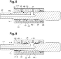
- the figure 8 shows a roto-percussive hydraulic drill 2 according to a seventh embodiment of the invention which differs from the first embodiment essentially in that the roto-percussive hydraulic perforator 2 further comprises a front emergency seal 44 which is annular and which extends around the fitting 14, the front emergency seal 44 being located at the front of the front main seal 26 and which is configured to cooperate in a sealed manner with a third portion of fitting 14.3 of fitting 14.
- the injection body 21 comprises a front portion 21.4 comprising a front inner surface which is generally cylindrical, the front emergency seal 44 being fixed in an annular fixing groove provided on the front inner surface.
- the third fitting portion 14.3 is generally cylindrical and has a third external diameter which is substantially identical to the first external diameter of the first fitting portion 14.1, and the front internal surface has an internal diameter which is substantially identical to the internal diameter of the first internal surface.
- the roto-percussive hydraulic perforator 2 further comprises an additional leakage passage 45 which is defined between the fitting 14 and the injection body 21 and which extends from the front main seal 26 to the front emergency seal 44. Leakage flow is intended to flow into the additional leak passage 45 in the event of an injection fluid leak at the level of the front main seal 26.
- the additional leakage passage 45 has a passage section which varies between the front main seal 26 and the front emergency seal 44, and comprises in particular an additional evacuation chamber 46 which is annular and which is extends around the fitting 14.
- the additional evacuation chamber 46 is located axially between the front main seal 26 and the front emergency seal 44.
- the injection body 21 comprises an additional annular evacuation groove 47 opening into the longitudinal passage 22 and partly delimiting the additional evacuation chamber 46.
- the roto-percussive hydraulic perforator 2 also comprises one or more additional fluid discharge orifice(s) 48 provided on the injection body 21 and opening, for example radially, into the discharge chamber. 46.
- the or each additional fluid discharge port 48 is configured to discharge a leak flow flowing in the additional leak passage 45 to the outside of the roto-percussive hydraulic drill 2.
- the injection body 21 comprises a pressurization channel 49 which extends over at least part of the length of the main body and which opens substantially radially into the front internal surface.
- a pressurization channel 49 is supplied with pressurization fluid, generally compressible, ideally lubricated, making it possible to limit rotational and translational friction between the fitting 14 and the injection body 21.
- the figure 9 represents a roto-percussive hydraulic perforator 2 according to an eighth embodiment of the invention which differs from the seventh embodiment essentially in that the third external diameter of the third fitting portion 14.3 is strictly less than the first external diameter of the first fitting portion 14.1, in that the front internal surface has an internal diameter which is less than the internal diameter of the first internal surface, and in that the roto-percussive hydraulic perforator 2 comprises means for generating pressure drops arranged in the additional leakage passage 45 and configured to generate pressure drops in the additional leakage passage 45 when a leakage flow flows in the additional leakage passage 45.
- the means for generating pressure drops comprise an additional deflection surface 51 which is annular and which is provided on the injection body 21.
- the additional deflection surface 51 connects the front internal surface to the first internal surface.
- the additional deflection surface 51 extends substantially perpendicular to the longitudinal axis of the fitting 14, and is configured to deflect a leakage flow, flowing in the additional leakage passage 45 in the direction of the seal emergency front 44, from a direction of flow substantially parallel to the longitudinal axis of the fitting 14 to a direction of flow which is perpendicular to the longitudinal axis of the fitting 14.
- the surface additional deflection 51 is configured to deflect the leakage flow in the direction of the longitudinal axis of the fitting 14.
- the additional deflection surface 51 could have a generally frustoconical shape and converge in the direction of the front emergency seal 44.
- the additional deflection surface 51 could for example be inclined with respect to the longitudinal axis of the fitting 14 according to an angle of inclination comprised between 1 and 89°, for example between 30 and 60°, and advantageously of approximately 45°.
- the pressurization pressure prevailing in front of the front emergency seal 44 in due to the presence of the pressurization channel 49, will be sufficient to limit the risks of penetration of injection fluid via the pressurization channel into the pressurization zone or the hydraulic zone of the roto-percussive hydraulic perforator.
- the presence of the additional deflection surface 51 therefore makes it possible to further increase the reliability of the roto-percussive hydraulic perforator 2 according to the present invention.
- the additional deflection surface 51 could converge in the direction of the main front seal 26 and be configured to direct a leakage flow, flowing into the additional leakage passage 45 in direction of the front emergency seal 44, towards the main front seal 26.
- the additional deflection surface 51 is inclined with respect to the longitudinal axis of the fitting 14 at an angle of inclination comprised between 91 and 179°, for example between 120 and 150°, and advantageously around 135°.
- the injection body 21 could comprise a rear intermediate portion which would be located axially between the rear main seal 27 and the rear emergency seal 28, and the intermediate portion would have an inner circumferential surface having a surface roughness configured to generate pressure drops in the leakage passage 29 (in addition to the pressure drops generated by the deflection surface 34) when leakage flow flows through the leakage passage 29.
- the means for generating losses would be formed by the deflection surface 34 and the surface roughness of the internal circumferential surface.
- the fitting 14 could comprise, in addition to the deflection surface 34, a connecting portion located axially between the first and second fitting portions, the connecting portion comprising a surface outer circumferential having a surface roughness that is configured to generate pressure drops in the leakage passage (in addition to the pressure drops generated by the deflection surface 34) when leakage flow flows through the leakage passage .
- the means for generating pressure drops would be formed by the deflection surface 34 and the surface roughness of the outer circumferential surface.
Landscapes
- Engineering & Computer Science (AREA)
- Geology (AREA)
- Life Sciences & Earth Sciences (AREA)
- Mining & Mineral Resources (AREA)
- Mechanical Engineering (AREA)
- Fluid Mechanics (AREA)
- Physics & Mathematics (AREA)
- Environmental & Geological Engineering (AREA)
- General Life Sciences & Earth Sciences (AREA)
- Geochemistry & Mineralogy (AREA)
- Earth Drilling (AREA)
- Percussive Tools And Related Accessories (AREA)
- Organic Low-Molecular-Weight Compounds And Preparation Thereof (AREA)
- Processing Of Stones Or Stones Resemblance Materials (AREA)
Applications Claiming Priority (1)
| Application Number | Priority Date | Filing Date | Title |
|---|---|---|---|
| FR2104176A FR3122207B1 (fr) | 2021-04-21 | 2021-04-21 | Perforateur hydraulique roto-percutant |
Publications (3)
| Publication Number | Publication Date |
|---|---|
| EP4080011A1 true EP4080011A1 (de) | 2022-10-26 |
| EP4080011B1 EP4080011B1 (de) | 2024-08-21 |
| EP4080011C0 EP4080011C0 (de) | 2024-08-21 |
Family
ID=76283975
Family Applications (1)
| Application Number | Title | Priority Date | Filing Date |
|---|---|---|---|
| EP22165675.4A Active EP4080011B1 (de) | 2021-04-21 | 2022-03-30 | Hydraulische drehschlagbohrmaschine |
Country Status (9)
| Country | Link |
|---|---|
| US (1) | US11938606B2 (de) |
| EP (1) | EP4080011B1 (de) |
| JP (1) | JP7787004B2 (de) |
| KR (1) | KR20220145285A (de) |
| CN (1) | CN115217411A (de) |
| AU (1) | AU2022202437A1 (de) |
| CA (1) | CA3153570C (de) |
| FR (1) | FR3122207B1 (de) |
| ZA (1) | ZA202203584B (de) |
Families Citing this family (2)
| Publication number | Priority date | Publication date | Assignee | Title |
|---|---|---|---|---|
| FR3108931B1 (fr) * | 2020-04-02 | 2022-04-08 | Montabert Roger | Perforateur hydraulique roto-percutant pourvu d’un emmanchement équipé de cannelures d’accouplement |
| JP7707464B1 (ja) * | 2025-03-13 | 2025-07-14 | 茂 宮古 | ドリルヘッド用冷却油回収機構 |
Citations (4)
| Publication number | Priority date | Publication date | Assignee | Title |
|---|---|---|---|---|
| EP0058650A1 (de) * | 1981-02-11 | 1982-08-25 | Atlas Copco Aktiebolag | Hydraulisch betriebene Schlagvorrichtung |
| WO2008100193A1 (en) * | 2007-02-14 | 2008-08-21 | Atlas Copco Rock Drills Ab | Apparatus for rock drilling |
| WO2009148375A1 (en) * | 2008-06-03 | 2009-12-10 | Atlas Copco Rock Drills Ab | Arrangement and method comprising a flushing head for a rock drilling machine, and rock drilling machine comprising the arrangement |
| FR3026041A1 (fr) * | 2014-09-18 | 2016-03-25 | Montabert Roger | Appareil de perforation hydraulique destine a la perforation de trous de mine |
Family Cites Families (9)
| Publication number | Priority date | Publication date | Assignee | Title |
|---|---|---|---|---|
| US3981368A (en) * | 1974-12-31 | 1976-09-21 | Sandvik Aktiebolag | Coupling means in a drilling machine |
| AT380534B (de) * | 1983-01-07 | 1986-06-10 | Ver Edelstahlwerke Ag | Drehschlag-, dreh- oder schlagwerk |
| SE466319B (sv) * | 1989-03-07 | 1992-01-27 | Atlas Copco Constr & Mining | Taetningsanordning foer vaetskespolning vid slaaende bergborrning |
| AUPO698197A0 (en) * | 1997-05-26 | 1997-06-19 | Sds Digger Tools Pty Ltd | A percussive hammer drill |
| JP4514900B2 (ja) | 2000-05-31 | 2010-07-28 | 古河機械金属株式会社 | 油圧打撃装置の緩衝機構 |
| FR2837523B1 (fr) * | 2002-03-19 | 2004-05-14 | Montabert Sa | Marteau perforateur hydraulique roto-percutant |
| SE534770C2 (sv) * | 2010-01-11 | 2011-12-13 | Atlas Copco Rock Drills Ab | Slående bergborrmaskin innefattande en frontdel med ett spolhus |
| CN106246098B (zh) | 2016-11-01 | 2018-03-30 | 山东中瑞工程机械有限公司 | 具有自动调节排气量功能的内缸式潜孔冲击器 |
| FR3077752B1 (fr) * | 2018-02-14 | 2020-01-31 | Montabert | Perforateur hydraulique roto-percutant pourvu d’une chambre de commande reliee en permanence a un accumulateur basse pression |
-
2021
- 2021-04-21 FR FR2104176A patent/FR3122207B1/fr active Active
-
2022
- 2022-03-29 ZA ZA2022/03584A patent/ZA202203584B/en unknown
- 2022-03-29 CA CA3153570A patent/CA3153570C/fr active Active
- 2022-03-30 EP EP22165675.4A patent/EP4080011B1/de active Active
- 2022-04-08 JP JP2022064710A patent/JP7787004B2/ja active Active
- 2022-04-13 AU AU2022202437A patent/AU2022202437A1/en active Pending
- 2022-04-19 KR KR1020220048062A patent/KR20220145285A/ko active Pending
- 2022-04-21 CN CN202210423875.7A patent/CN115217411A/zh active Pending
- 2022-04-21 US US17/725,869 patent/US11938606B2/en active Active
Patent Citations (4)
| Publication number | Priority date | Publication date | Assignee | Title |
|---|---|---|---|---|
| EP0058650A1 (de) * | 1981-02-11 | 1982-08-25 | Atlas Copco Aktiebolag | Hydraulisch betriebene Schlagvorrichtung |
| WO2008100193A1 (en) * | 2007-02-14 | 2008-08-21 | Atlas Copco Rock Drills Ab | Apparatus for rock drilling |
| WO2009148375A1 (en) * | 2008-06-03 | 2009-12-10 | Atlas Copco Rock Drills Ab | Arrangement and method comprising a flushing head for a rock drilling machine, and rock drilling machine comprising the arrangement |
| FR3026041A1 (fr) * | 2014-09-18 | 2016-03-25 | Montabert Roger | Appareil de perforation hydraulique destine a la perforation de trous de mine |
Also Published As
| Publication number | Publication date |
|---|---|
| CA3153570C (fr) | 2026-02-17 |
| EP4080011B1 (de) | 2024-08-21 |
| CN115217411A (zh) | 2022-10-21 |
| FR3122207A1 (fr) | 2022-10-28 |
| AU2022202437A1 (en) | 2022-11-10 |
| US11938606B2 (en) | 2024-03-26 |
| EP4080011C0 (de) | 2024-08-21 |
| JP2022166824A (ja) | 2022-11-02 |
| JP7787004B2 (ja) | 2025-12-16 |
| CA3153570A1 (fr) | 2022-10-21 |
| KR20220145285A (ko) | 2022-10-28 |
| US20220339768A1 (en) | 2022-10-27 |
| FR3122207B1 (fr) | 2023-04-28 |
| ZA202203584B (en) | 2022-11-30 |
Similar Documents
| Publication | Publication Date | Title |
|---|---|---|
| EP3752325B1 (de) | Hydraulischer drehschlagbohrer mit einer permanent an einem niederdruckspeicher angeschlossenen steuerkammer | |
| EP4080011B1 (de) | Hydraulische drehschlagbohrmaschine | |
| FR2647870A1 (fr) | Appareil de percussion hydraulique avec dispositif d'amortissement des ondes de choc en retour | |
| EP3818266B1 (de) | Hydrostatische maschine mit einem nockenring | |
| EP4053374B1 (de) | Hydraulischer drehschlagbohrer mit einem anschlagkolben und einer bremskammer | |
| FR2837523A1 (fr) | Marteau perforateur hydraulique roto-percutant | |
| FR3058664B1 (fr) | Appareil a percussions | |
| CA3118204A1 (fr) | Appareil hydraulique a percussions equipe d'un dispositif d'etancheite | |
| EP3194122A1 (de) | Hydraulische bohrvorrichtung zum bohren von sprenglöchern | |
| EP4052854B1 (de) | Hydraulischer drehschlagbohrer mit einem anschlagkolben | |
| CA2394643A1 (fr) | Dispositif d'alimentation hydraulique d'un appareil de forage roto-percutant | |
| FR2596681A1 (fr) | Appareil de percussion hydraulique avec dispositif d'amortissement des ondes de choc en retour | |
| EP4127374B1 (de) | Hydraulischer drehschlagbohrer mit einem schaft mit kopplungskeilen | |
| WO2012089949A1 (fr) | Appareil rotopercutant hydraulique destiné à la perforation de trous de mine | |
| CA3172279C (fr) | Perforateur hydraulique roto-percutant pourvu d'un emmanchement equipe de cannelures d'accouplement | |
| FR2800808A1 (fr) | Cylindre emetteur pour une installation hydraulique | |
| BE833220A (fr) | Machine hydraulique a percussion | |
| FR2783889A1 (fr) | Dispositif d'etancheite entre une tete de coupe d'un tunnelier et un arbre horizontal fixe |
Legal Events
| Date | Code | Title | Description |
|---|---|---|---|
| PUAI | Public reference made under article 153(3) epc to a published international application that has entered the european phase |
Free format text: ORIGINAL CODE: 0009012 |
|
| STAA | Information on the status of an ep patent application or granted ep patent |
Free format text: STATUS: THE APPLICATION HAS BEEN PUBLISHED |
|
| AK | Designated contracting states |
Kind code of ref document: A1 Designated state(s): AL AT BE BG CH CY CZ DE DK EE ES FI FR GB GR HR HU IE IS IT LI LT LU LV MC MK MT NL NO PL PT RO RS SE SI SK SM TR |
|
| STAA | Information on the status of an ep patent application or granted ep patent |
Free format text: STATUS: REQUEST FOR EXAMINATION WAS MADE |
|
| 17P | Request for examination filed |
Effective date: 20230307 |
|
| RBV | Designated contracting states (corrected) |
Designated state(s): AL AT BE BG CH CY CZ DE DK EE ES FI FR GB GR HR HU IE IS IT LI LT LU LV MC MK MT NL NO PL PT RO RS SE SI SK SM TR |
|
| GRAP | Despatch of communication of intention to grant a patent |
Free format text: ORIGINAL CODE: EPIDOSNIGR1 |
|
| STAA | Information on the status of an ep patent application or granted ep patent |
Free format text: STATUS: GRANT OF PATENT IS INTENDED |
|
| RIC1 | Information provided on ipc code assigned before grant |
Ipc: B25D 17/22 20060101ALI20240229BHEP Ipc: B25D 17/24 20060101ALI20240229BHEP Ipc: E21B 1/38 20060101ALI20240229BHEP Ipc: E21B 1/26 20060101AFI20240229BHEP |
|
| INTG | Intention to grant announced |
Effective date: 20240319 |
|
| GRAS | Grant fee paid |
Free format text: ORIGINAL CODE: EPIDOSNIGR3 |
|
| GRAA | (expected) grant |
Free format text: ORIGINAL CODE: 0009210 |
|
| STAA | Information on the status of an ep patent application or granted ep patent |
Free format text: STATUS: THE PATENT HAS BEEN GRANTED |
|
| AK | Designated contracting states |
Kind code of ref document: B1 Designated state(s): AL AT BE BG CH CY CZ DE DK EE ES FI FR GB GR HR HU IE IS IT LI LT LU LV MC MK MT NL NO PL PT RO RS SE SI SK SM TR |
|
| REG | Reference to a national code |
Ref country code: GB Ref legal event code: FG4D Free format text: NOT ENGLISH |
|
| REG | Reference to a national code |
Ref country code: CH Ref legal event code: EP |
|
| REG | Reference to a national code |
Ref country code: DE Ref legal event code: R096 Ref document number: 602022005412 Country of ref document: DE |
|
| REG | Reference to a national code |
Ref country code: IE Ref legal event code: FG4D Free format text: LANGUAGE OF EP DOCUMENT: FRENCH |
|
| U01 | Request for unitary effect filed |
Effective date: 20240912 |
|
| U07 | Unitary effect registered |
Designated state(s): AT BE BG DE DK EE FI FR IT LT LU LV MT NL PT RO SE SI Effective date: 20241002 |
|
| PG25 | Lapsed in a contracting state [announced via postgrant information from national office to epo] |
Ref country code: NO Free format text: LAPSE BECAUSE OF FAILURE TO SUBMIT A TRANSLATION OF THE DESCRIPTION OR TO PAY THE FEE WITHIN THE PRESCRIBED TIME-LIMIT Effective date: 20241121 |
|
| PG25 | Lapsed in a contracting state [announced via postgrant information from national office to epo] |
Ref country code: PL Free format text: LAPSE BECAUSE OF FAILURE TO SUBMIT A TRANSLATION OF THE DESCRIPTION OR TO PAY THE FEE WITHIN THE PRESCRIBED TIME-LIMIT Effective date: 20240821 Ref country code: GR Free format text: LAPSE BECAUSE OF FAILURE TO SUBMIT A TRANSLATION OF THE DESCRIPTION OR TO PAY THE FEE WITHIN THE PRESCRIBED TIME-LIMIT Effective date: 20241122 |
|
| PG25 | Lapsed in a contracting state [announced via postgrant information from national office to epo] |
Ref country code: IS Free format text: LAPSE BECAUSE OF FAILURE TO SUBMIT A TRANSLATION OF THE DESCRIPTION OR TO PAY THE FEE WITHIN THE PRESCRIBED TIME-LIMIT Effective date: 20241221 |
|
| PG25 | Lapsed in a contracting state [announced via postgrant information from national office to epo] |
Ref country code: HR Free format text: LAPSE BECAUSE OF FAILURE TO SUBMIT A TRANSLATION OF THE DESCRIPTION OR TO PAY THE FEE WITHIN THE PRESCRIBED TIME-LIMIT Effective date: 20240821 |
|
| PG25 | Lapsed in a contracting state [announced via postgrant information from national office to epo] |
Ref country code: ES Free format text: LAPSE BECAUSE OF FAILURE TO SUBMIT A TRANSLATION OF THE DESCRIPTION OR TO PAY THE FEE WITHIN THE PRESCRIBED TIME-LIMIT Effective date: 20240821 Ref country code: RS Free format text: LAPSE BECAUSE OF FAILURE TO SUBMIT A TRANSLATION OF THE DESCRIPTION OR TO PAY THE FEE WITHIN THE PRESCRIBED TIME-LIMIT Effective date: 20241121 |
|
| PG25 | Lapsed in a contracting state [announced via postgrant information from national office to epo] |
Ref country code: RS Free format text: LAPSE BECAUSE OF FAILURE TO SUBMIT A TRANSLATION OF THE DESCRIPTION OR TO PAY THE FEE WITHIN THE PRESCRIBED TIME-LIMIT Effective date: 20241121 Ref country code: PL Free format text: LAPSE BECAUSE OF FAILURE TO SUBMIT A TRANSLATION OF THE DESCRIPTION OR TO PAY THE FEE WITHIN THE PRESCRIBED TIME-LIMIT Effective date: 20240821 Ref country code: NO Free format text: LAPSE BECAUSE OF FAILURE TO SUBMIT A TRANSLATION OF THE DESCRIPTION OR TO PAY THE FEE WITHIN THE PRESCRIBED TIME-LIMIT Effective date: 20241121 Ref country code: IS Free format text: LAPSE BECAUSE OF FAILURE TO SUBMIT A TRANSLATION OF THE DESCRIPTION OR TO PAY THE FEE WITHIN THE PRESCRIBED TIME-LIMIT Effective date: 20241221 Ref country code: HR Free format text: LAPSE BECAUSE OF FAILURE TO SUBMIT A TRANSLATION OF THE DESCRIPTION OR TO PAY THE FEE WITHIN THE PRESCRIBED TIME-LIMIT Effective date: 20240821 Ref country code: GR Free format text: LAPSE BECAUSE OF FAILURE TO SUBMIT A TRANSLATION OF THE DESCRIPTION OR TO PAY THE FEE WITHIN THE PRESCRIBED TIME-LIMIT Effective date: 20241122 Ref country code: ES Free format text: LAPSE BECAUSE OF FAILURE TO SUBMIT A TRANSLATION OF THE DESCRIPTION OR TO PAY THE FEE WITHIN THE PRESCRIBED TIME-LIMIT Effective date: 20240821 |
|
| PG25 | Lapsed in a contracting state [announced via postgrant information from national office to epo] |
Ref country code: SM Free format text: LAPSE BECAUSE OF FAILURE TO SUBMIT A TRANSLATION OF THE DESCRIPTION OR TO PAY THE FEE WITHIN THE PRESCRIBED TIME-LIMIT Effective date: 20240821 |
|
| PG25 | Lapsed in a contracting state [announced via postgrant information from national office to epo] |
Ref country code: CZ Free format text: LAPSE BECAUSE OF FAILURE TO SUBMIT A TRANSLATION OF THE DESCRIPTION OR TO PAY THE FEE WITHIN THE PRESCRIBED TIME-LIMIT Effective date: 20240821 |
|
| PG25 | Lapsed in a contracting state [announced via postgrant information from national office to epo] |
Ref country code: SK Free format text: LAPSE BECAUSE OF FAILURE TO SUBMIT A TRANSLATION OF THE DESCRIPTION OR TO PAY THE FEE WITHIN THE PRESCRIBED TIME-LIMIT Effective date: 20240821 |
|
| U20 | Renewal fee for the european patent with unitary effect paid |
Year of fee payment: 4 Effective date: 20250331 |
|
| PLBE | No opposition filed within time limit |
Free format text: ORIGINAL CODE: 0009261 |
|
| STAA | Information on the status of an ep patent application or granted ep patent |
Free format text: STATUS: NO OPPOSITION FILED WITHIN TIME LIMIT |
|
| 26N | No opposition filed |
Effective date: 20250522 |
|
| PG25 | Lapsed in a contracting state [announced via postgrant information from national office to epo] |
Ref country code: MC Free format text: LAPSE BECAUSE OF FAILURE TO SUBMIT A TRANSLATION OF THE DESCRIPTION OR TO PAY THE FEE WITHIN THE PRESCRIBED TIME-LIMIT Effective date: 20240821 |
|
| REG | Reference to a national code |
Ref country code: CH Ref legal event code: H13 Free format text: ST27 STATUS EVENT CODE: U-0-0-H10-H13 (AS PROVIDED BY THE NATIONAL OFFICE) Effective date: 20251023 |
|
| PG25 | Lapsed in a contracting state [announced via postgrant information from national office to epo] |
Ref country code: CH Free format text: LAPSE BECAUSE OF NON-PAYMENT OF DUE FEES Effective date: 20250331 |
|
| PG25 | Lapsed in a contracting state [announced via postgrant information from national office to epo] |
Ref country code: IE Free format text: LAPSE BECAUSE OF NON-PAYMENT OF DUE FEES Effective date: 20250330 |
|
| U20 | Renewal fee for the european patent with unitary effect paid |
Year of fee payment: 5 Effective date: 20260213 |
|
| PGFP | Annual fee paid to national office [announced via postgrant information from national office to epo] |
Ref country code: TR Payment date: 20260317 Year of fee payment: 5 |