EP4080035A1 - Verbrennungsmotorsystem - Google Patents
Verbrennungsmotorsystem Download PDFInfo
- Publication number
- EP4080035A1 EP4080035A1 EP21169650.5A EP21169650A EP4080035A1 EP 4080035 A1 EP4080035 A1 EP 4080035A1 EP 21169650 A EP21169650 A EP 21169650A EP 4080035 A1 EP4080035 A1 EP 4080035A1
- Authority
- EP
- European Patent Office
- Prior art keywords
- cylinders
- outlet
- inlet
- internal combustion
- combustion engine
- Prior art date
- Legal status (The legal status is an assumption and is not a legal conclusion. Google has not performed a legal analysis and makes no representation as to the accuracy of the status listed.)
- Withdrawn
Links
Images


Classifications
-
- F—MECHANICAL ENGINEERING; LIGHTING; HEATING; WEAPONS; BLASTING
- F02—COMBUSTION ENGINES; HOT-GAS OR COMBUSTION-PRODUCT ENGINE PLANTS
- F02M—SUPPLYING COMBUSTION ENGINES IN GENERAL WITH COMBUSTIBLE MIXTURES OR CONSTITUENTS THEREOF
- F02M35/00—Combustion-air cleaners, air intakes, intake silencers, or induction systems specially adapted for, or arranged on, internal-combustion engines
- F02M35/10—Air intakes; Induction systems
- F02M35/10091—Air intakes; Induction systems characterised by details of intake ducts: shapes; connections; arrangements
-
- F—MECHANICAL ENGINEERING; LIGHTING; HEATING; WEAPONS; BLASTING
- F02—COMBUSTION ENGINES; HOT-GAS OR COMBUSTION-PRODUCT ENGINE PLANTS
- F02M—SUPPLYING COMBUSTION ENGINES IN GENERAL WITH COMBUSTIBLE MIXTURES OR CONSTITUENTS THEREOF
- F02M26/00—Engine-pertinent apparatus for adding exhaust gases to combustion-air, main fuel or fuel-air mixture, e.g. by exhaust gas recirculation [EGR] systems
- F02M26/65—Constructional details of EGR valves
- F02M26/71—Multi-way valves
-
- B—PERFORMING OPERATIONS; TRANSPORTING
- B01—PHYSICAL OR CHEMICAL PROCESSES OR APPARATUS IN GENERAL
- B01F—MIXING, e.g. DISSOLVING, EMULSIFYING OR DISPERSING
- B01F23/00—Mixing according to the phases to be mixed, e.g. dispersing or emulsifying
- B01F23/10—Mixing gases with gases
- B01F23/19—Mixing systems, i.e. flow charts or diagrams; Arrangements, e.g. comprising controlling means
-
- B—PERFORMING OPERATIONS; TRANSPORTING
- B01—PHYSICAL OR CHEMICAL PROCESSES OR APPARATUS IN GENERAL
- B01F—MIXING, e.g. DISSOLVING, EMULSIFYING OR DISPERSING
- B01F25/00—Flow mixers; Mixers for falling materials, e.g. solid particles
- B01F25/105—Mixing heads, i.e. compact mixing units or modules, using mixing valves for feeding and mixing at least two components
- B01F25/1051—Mixing heads, i.e. compact mixing units or modules, using mixing valves for feeding and mixing at least two components of the mixing valve type
-
- F—MECHANICAL ENGINEERING; LIGHTING; HEATING; WEAPONS; BLASTING
- F01—MACHINES OR ENGINES IN GENERAL; ENGINE PLANTS IN GENERAL; STEAM ENGINES
- F01N—GAS-FLOW SILENCERS OR EXHAUST APPARATUS FOR MACHINES OR ENGINES IN GENERAL; GAS-FLOW SILENCERS OR EXHAUST APPARATUS FOR INTERNAL-COMBUSTION ENGINES
- F01N13/00—Exhaust or silencing apparatus characterised by constructional features
- F01N13/08—Other arrangements or adaptations of exhaust conduits
- F01N13/10—Other arrangements or adaptations of exhaust conduits of exhaust manifolds
-
- F—MECHANICAL ENGINEERING; LIGHTING; HEATING; WEAPONS; BLASTING
- F01—MACHINES OR ENGINES IN GENERAL; ENGINE PLANTS IN GENERAL; STEAM ENGINES
- F01N—GAS-FLOW SILENCERS OR EXHAUST APPARATUS FOR MACHINES OR ENGINES IN GENERAL; GAS-FLOW SILENCERS OR EXHAUST APPARATUS FOR INTERNAL-COMBUSTION ENGINES
- F01N13/00—Exhaust or silencing apparatus characterised by constructional features
- F01N13/08—Other arrangements or adaptations of exhaust conduits
- F01N13/10—Other arrangements or adaptations of exhaust conduits of exhaust manifolds
- F01N13/107—More than one exhaust manifold or exhaust collector
-
- F—MECHANICAL ENGINEERING; LIGHTING; HEATING; WEAPONS; BLASTING
- F02—COMBUSTION ENGINES; HOT-GAS OR COMBUSTION-PRODUCT ENGINE PLANTS
- F02D—CONTROLLING COMBUSTION ENGINES
- F02D17/00—Controlling engines by cutting out individual cylinders; Rendering engines inoperative or idling
- F02D17/02—Cutting-out
-
- F—MECHANICAL ENGINEERING; LIGHTING; HEATING; WEAPONS; BLASTING
- F02—COMBUSTION ENGINES; HOT-GAS OR COMBUSTION-PRODUCT ENGINE PLANTS
- F02D—CONTROLLING COMBUSTION ENGINES
- F02D41/00—Electrical control of supply of combustible mixture or its constituents
- F02D41/0002—Controlling intake air
-
- F—MECHANICAL ENGINEERING; LIGHTING; HEATING; WEAPONS; BLASTING
- F02—COMBUSTION ENGINES; HOT-GAS OR COMBUSTION-PRODUCT ENGINE PLANTS
- F02D—CONTROLLING COMBUSTION ENGINES
- F02D41/00—Electrical control of supply of combustible mixture or its constituents
- F02D41/0025—Controlling engines characterised by use of non-liquid fuels, pluralities of fuels, or non-fuel substances added to the combustible mixtures
- F02D41/0047—Controlling exhaust gas recirculation [EGR]
-
- F—MECHANICAL ENGINEERING; LIGHTING; HEATING; WEAPONS; BLASTING
- F02—COMBUSTION ENGINES; HOT-GAS OR COMBUSTION-PRODUCT ENGINE PLANTS
- F02D—CONTROLLING COMBUSTION ENGINES
- F02D41/00—Electrical control of supply of combustible mixture or its constituents
- F02D41/008—Controlling each cylinder individually
- F02D41/0082—Controlling each cylinder individually per groups or banks
-
- F—MECHANICAL ENGINEERING; LIGHTING; HEATING; WEAPONS; BLASTING
- F02—COMBUSTION ENGINES; HOT-GAS OR COMBUSTION-PRODUCT ENGINE PLANTS
- F02D—CONTROLLING COMBUSTION ENGINES
- F02D41/00—Electrical control of supply of combustible mixture or its constituents
- F02D41/008—Controlling each cylinder individually
- F02D41/0087—Selective cylinder activation, i.e. partial cylinder operation
-
- F—MECHANICAL ENGINEERING; LIGHTING; HEATING; WEAPONS; BLASTING
- F02—COMBUSTION ENGINES; HOT-GAS OR COMBUSTION-PRODUCT ENGINE PLANTS
- F02M—SUPPLYING COMBUSTION ENGINES IN GENERAL WITH COMBUSTIBLE MIXTURES OR CONSTITUENTS THEREOF
- F02M26/00—Engine-pertinent apparatus for adding exhaust gases to combustion-air, main fuel or fuel-air mixture, e.g. by exhaust gas recirculation [EGR] systems
- F02M26/02—EGR systems specially adapted for supercharged engines
- F02M26/04—EGR systems specially adapted for supercharged engines with a single turbocharger
-
- F—MECHANICAL ENGINEERING; LIGHTING; HEATING; WEAPONS; BLASTING
- F02—COMBUSTION ENGINES; HOT-GAS OR COMBUSTION-PRODUCT ENGINE PLANTS
- F02M—SUPPLYING COMBUSTION ENGINES IN GENERAL WITH COMBUSTIBLE MIXTURES OR CONSTITUENTS THEREOF
- F02M26/00—Engine-pertinent apparatus for adding exhaust gases to combustion-air, main fuel or fuel-air mixture, e.g. by exhaust gas recirculation [EGR] systems
- F02M26/02—EGR systems specially adapted for supercharged engines
- F02M26/04—EGR systems specially adapted for supercharged engines with a single turbocharger
- F02M26/05—High pressure loops, i.e. wherein recirculated exhaust gas is taken out from the exhaust system upstream of the turbine and reintroduced into the intake system downstream of the compressor
-
- F—MECHANICAL ENGINEERING; LIGHTING; HEATING; WEAPONS; BLASTING
- F02—COMBUSTION ENGINES; HOT-GAS OR COMBUSTION-PRODUCT ENGINE PLANTS
- F02M—SUPPLYING COMBUSTION ENGINES IN GENERAL WITH COMBUSTIBLE MIXTURES OR CONSTITUENTS THEREOF
- F02M26/00—Engine-pertinent apparatus for adding exhaust gases to combustion-air, main fuel or fuel-air mixture, e.g. by exhaust gas recirculation [EGR] systems
- F02M26/13—Arrangement or layout of EGR passages, e.g. in relation to specific engine parts or for incorporation of accessories
- F02M26/14—Arrangement or layout of EGR passages, e.g. in relation to specific engine parts or for incorporation of accessories in relation to the exhaust system
-
- F—MECHANICAL ENGINEERING; LIGHTING; HEATING; WEAPONS; BLASTING
- F02—COMBUSTION ENGINES; HOT-GAS OR COMBUSTION-PRODUCT ENGINE PLANTS
- F02M—SUPPLYING COMBUSTION ENGINES IN GENERAL WITH COMBUSTIBLE MIXTURES OR CONSTITUENTS THEREOF
- F02M26/00—Engine-pertinent apparatus for adding exhaust gases to combustion-air, main fuel or fuel-air mixture, e.g. by exhaust gas recirculation [EGR] systems
- F02M26/13—Arrangement or layout of EGR passages, e.g. in relation to specific engine parts or for incorporation of accessories
- F02M26/17—Arrangement or layout of EGR passages, e.g. in relation to specific engine parts or for incorporation of accessories in relation to the intake system
-
- F—MECHANICAL ENGINEERING; LIGHTING; HEATING; WEAPONS; BLASTING
- F02—COMBUSTION ENGINES; HOT-GAS OR COMBUSTION-PRODUCT ENGINE PLANTS
- F02M—SUPPLYING COMBUSTION ENGINES IN GENERAL WITH COMBUSTIBLE MIXTURES OR CONSTITUENTS THEREOF
- F02M26/00—Engine-pertinent apparatus for adding exhaust gases to combustion-air, main fuel or fuel-air mixture, e.g. by exhaust gas recirculation [EGR] systems
- F02M26/13—Arrangement or layout of EGR passages, e.g. in relation to specific engine parts or for incorporation of accessories
- F02M26/17—Arrangement or layout of EGR passages, e.g. in relation to specific engine parts or for incorporation of accessories in relation to the intake system
- F02M26/19—Means for improving the mixing of air and recirculated exhaust gases, e.g. venturis or multiple openings to the intake system
-
- F—MECHANICAL ENGINEERING; LIGHTING; HEATING; WEAPONS; BLASTING
- F02—COMBUSTION ENGINES; HOT-GAS OR COMBUSTION-PRODUCT ENGINE PLANTS
- F02M—SUPPLYING COMBUSTION ENGINES IN GENERAL WITH COMBUSTIBLE MIXTURES OR CONSTITUENTS THEREOF
- F02M26/00—Engine-pertinent apparatus for adding exhaust gases to combustion-air, main fuel or fuel-air mixture, e.g. by exhaust gas recirculation [EGR] systems
- F02M26/13—Arrangement or layout of EGR passages, e.g. in relation to specific engine parts or for incorporation of accessories
- F02M26/17—Arrangement or layout of EGR passages, e.g. in relation to specific engine parts or for incorporation of accessories in relation to the intake system
- F02M26/21—Arrangement or layout of EGR passages, e.g. in relation to specific engine parts or for incorporation of accessories in relation to the intake system with EGR valves located at or near the connection to the intake system
-
- F—MECHANICAL ENGINEERING; LIGHTING; HEATING; WEAPONS; BLASTING
- F02—COMBUSTION ENGINES; HOT-GAS OR COMBUSTION-PRODUCT ENGINE PLANTS
- F02M—SUPPLYING COMBUSTION ENGINES IN GENERAL WITH COMBUSTIBLE MIXTURES OR CONSTITUENTS THEREOF
- F02M26/00—Engine-pertinent apparatus for adding exhaust gases to combustion-air, main fuel or fuel-air mixture, e.g. by exhaust gas recirculation [EGR] systems
- F02M26/13—Arrangement or layout of EGR passages, e.g. in relation to specific engine parts or for incorporation of accessories
- F02M26/38—Arrangement or layout of EGR passages, e.g. in relation to specific engine parts or for incorporation of accessories with two or more EGR valves disposed in parallel
-
- F—MECHANICAL ENGINEERING; LIGHTING; HEATING; WEAPONS; BLASTING
- F02—COMBUSTION ENGINES; HOT-GAS OR COMBUSTION-PRODUCT ENGINE PLANTS
- F02M—SUPPLYING COMBUSTION ENGINES IN GENERAL WITH COMBUSTIBLE MIXTURES OR CONSTITUENTS THEREOF
- F02M26/00—Engine-pertinent apparatus for adding exhaust gases to combustion-air, main fuel or fuel-air mixture, e.g. by exhaust gas recirculation [EGR] systems
- F02M26/13—Arrangement or layout of EGR passages, e.g. in relation to specific engine parts or for incorporation of accessories
- F02M26/42—Arrangement or layout of EGR passages, e.g. in relation to specific engine parts or for incorporation of accessories having two or more EGR passages; EGR systems specially adapted for engines having two or more cylinders
- F02M26/43—Arrangement or layout of EGR passages, e.g. in relation to specific engine parts or for incorporation of accessories having two or more EGR passages; EGR systems specially adapted for engines having two or more cylinders in which exhaust from only one cylinder or only a group of cylinders is directed to the intake of the engine
-
- F—MECHANICAL ENGINEERING; LIGHTING; HEATING; WEAPONS; BLASTING
- F02—COMBUSTION ENGINES; HOT-GAS OR COMBUSTION-PRODUCT ENGINE PLANTS
- F02M—SUPPLYING COMBUSTION ENGINES IN GENERAL WITH COMBUSTIBLE MIXTURES OR CONSTITUENTS THEREOF
- F02M26/00—Engine-pertinent apparatus for adding exhaust gases to combustion-air, main fuel or fuel-air mixture, e.g. by exhaust gas recirculation [EGR] systems
- F02M26/65—Constructional details of EGR valves
- F02M26/70—Flap valves; Rotary valves; Sliding valves; Resilient valves
-
- F—MECHANICAL ENGINEERING; LIGHTING; HEATING; WEAPONS; BLASTING
- F02—COMBUSTION ENGINES; HOT-GAS OR COMBUSTION-PRODUCT ENGINE PLANTS
- F02M—SUPPLYING COMBUSTION ENGINES IN GENERAL WITH COMBUSTIBLE MIXTURES OR CONSTITUENTS THEREOF
- F02M35/00—Combustion-air cleaners, air intakes, intake silencers, or induction systems specially adapted for, or arranged on, internal-combustion engines
- F02M35/10—Air intakes; Induction systems
- F02M35/10209—Fluid connections to the air intake system; their arrangement of pipes, valves or the like
- F02M35/10222—Exhaust gas recirculation [EGR]; Positive crankcase ventilation [PCV]; Additional air admission, lubricant or fuel vapour admission
-
- F—MECHANICAL ENGINEERING; LIGHTING; HEATING; WEAPONS; BLASTING
- F02—COMBUSTION ENGINES; HOT-GAS OR COMBUSTION-PRODUCT ENGINE PLANTS
- F02M—SUPPLYING COMBUSTION ENGINES IN GENERAL WITH COMBUSTIBLE MIXTURES OR CONSTITUENTS THEREOF
- F02M35/00—Combustion-air cleaners, air intakes, intake silencers, or induction systems specially adapted for, or arranged on, internal-combustion engines
- F02M35/10—Air intakes; Induction systems
- F02M35/10242—Devices or means connected to or integrated into air intakes; Air intakes combined with other engine or vehicle parts
- F02M35/10255—Arrangements of valves; Multi-way valves
-
- F—MECHANICAL ENGINEERING; LIGHTING; HEATING; WEAPONS; BLASTING
- F02—COMBUSTION ENGINES; HOT-GAS OR COMBUSTION-PRODUCT ENGINE PLANTS
- F02M—SUPPLYING COMBUSTION ENGINES IN GENERAL WITH COMBUSTIBLE MIXTURES OR CONSTITUENTS THEREOF
- F02M35/00—Combustion-air cleaners, air intakes, intake silencers, or induction systems specially adapted for, or arranged on, internal-combustion engines
- F02M35/10—Air intakes; Induction systems
- F02M35/104—Intake manifolds
-
- F—MECHANICAL ENGINEERING; LIGHTING; HEATING; WEAPONS; BLASTING
- F16—ENGINEERING ELEMENTS AND UNITS; GENERAL MEASURES FOR PRODUCING AND MAINTAINING EFFECTIVE FUNCTIONING OF MACHINES OR INSTALLATIONS; THERMAL INSULATION IN GENERAL
- F16K—VALVES; TAPS; COCKS; ACTUATING-FLOATS; DEVICES FOR VENTING OR AERATING
- F16K11/00—Multiple-way valves, e.g. mixing valves; Pipe fittings incorporating such valves
- F16K11/02—Multiple-way valves, e.g. mixing valves; Pipe fittings incorporating such valves with all movable sealing faces moving as one unit
- F16K11/04—Multiple-way valves, e.g. mixing valves; Pipe fittings incorporating such valves with all movable sealing faces moving as one unit comprising only lift valves
- F16K11/052—Multiple-way valves, e.g. mixing valves; Pipe fittings incorporating such valves with all movable sealing faces moving as one unit comprising only lift valves with pivoted closure members, e.g. butterfly valves
- F16K11/0525—Multiple-way valves, e.g. mixing valves; Pipe fittings incorporating such valves with all movable sealing faces moving as one unit comprising only lift valves with pivoted closure members, e.g. butterfly valves the closure members being pivoted around an essentially central axis
-
- F—MECHANICAL ENGINEERING; LIGHTING; HEATING; WEAPONS; BLASTING
- F01—MACHINES OR ENGINES IN GENERAL; ENGINE PLANTS IN GENERAL; STEAM ENGINES
- F01N—GAS-FLOW SILENCERS OR EXHAUST APPARATUS FOR MACHINES OR ENGINES IN GENERAL; GAS-FLOW SILENCERS OR EXHAUST APPARATUS FOR INTERNAL-COMBUSTION ENGINES
- F01N2240/00—Combination or association of two or more different exhaust treating devices, or of at least one such device with an auxiliary device, not covered by indexing codes F01N2230/00 or F01N2250/00, one of the devices being
- F01N2240/36—Combination or association of two or more different exhaust treating devices, or of at least one such device with an auxiliary device, not covered by indexing codes F01N2230/00 or F01N2250/00, one of the devices being an exhaust flap
-
- F—MECHANICAL ENGINEERING; LIGHTING; HEATING; WEAPONS; BLASTING
- F01—MACHINES OR ENGINES IN GENERAL; ENGINE PLANTS IN GENERAL; STEAM ENGINES
- F01N—GAS-FLOW SILENCERS OR EXHAUST APPARATUS FOR MACHINES OR ENGINES IN GENERAL; GAS-FLOW SILENCERS OR EXHAUST APPARATUS FOR INTERNAL-COMBUSTION ENGINES
- F01N2390/00—Arrangements for controlling or regulating exhaust apparatus
-
- F—MECHANICAL ENGINEERING; LIGHTING; HEATING; WEAPONS; BLASTING
- F02—COMBUSTION ENGINES; HOT-GAS OR COMBUSTION-PRODUCT ENGINE PLANTS
- F02B—INTERNAL-COMBUSTION PISTON ENGINES; COMBUSTION ENGINES IN GENERAL
- F02B27/00—Use of kinetic or wave energy of charge in induction systems, or of combustion residues in exhaust systems, for improving quantity of charge or for increasing removal of combustion residues
- F02B27/02—Use of kinetic or wave energy of charge in induction systems, or of combustion residues in exhaust systems, for improving quantity of charge or for increasing removal of combustion residues the systems having variable, i.e. adjustable, cross-sectional areas, chambers of variable volume, or like variable means
- F02B27/0226—Use of kinetic or wave energy of charge in induction systems, or of combustion residues in exhaust systems, for improving quantity of charge or for increasing removal of combustion residues the systems having variable, i.e. adjustable, cross-sectional areas, chambers of variable volume, or like variable means characterised by the means generating the charging effect
- F02B27/0247—Plenum chambers; Resonance chambers or resonance pipes
- F02B27/0252—Multiple plenum chambers or plenum chambers having inner separation walls, e.g. comprising valves for the same group of cylinders
-
- F—MECHANICAL ENGINEERING; LIGHTING; HEATING; WEAPONS; BLASTING
- F02—COMBUSTION ENGINES; HOT-GAS OR COMBUSTION-PRODUCT ENGINE PLANTS
- F02M—SUPPLYING COMBUSTION ENGINES IN GENERAL WITH COMBUSTIBLE MIXTURES OR CONSTITUENTS THEREOF
- F02M35/00—Combustion-air cleaners, air intakes, intake silencers, or induction systems specially adapted for, or arranged on, internal-combustion engines
- F02M35/10—Air intakes; Induction systems
- F02M35/10006—Air intakes; Induction systems characterised by the position of elements of the air intake system in direction of the air intake flow, i.e. between ambient air inlet and supply to the combustion chamber
- F02M35/10026—Plenum chambers
- F02M35/10045—Multiple plenum chambers; Plenum chambers having inner separation walls
-
- F—MECHANICAL ENGINEERING; LIGHTING; HEATING; WEAPONS; BLASTING
- F02—COMBUSTION ENGINES; HOT-GAS OR COMBUSTION-PRODUCT ENGINE PLANTS
- F02M—SUPPLYING COMBUSTION ENGINES IN GENERAL WITH COMBUSTIBLE MIXTURES OR CONSTITUENTS THEREOF
- F02M35/00—Combustion-air cleaners, air intakes, intake silencers, or induction systems specially adapted for, or arranged on, internal-combustion engines
- F02M35/10—Air intakes; Induction systems
- F02M35/104—Intake manifolds
- F02M35/108—Intake manifolds with primary and secondary intake passages
-
- Y—GENERAL TAGGING OF NEW TECHNOLOGICAL DEVELOPMENTS; GENERAL TAGGING OF CROSS-SECTIONAL TECHNOLOGIES SPANNING OVER SEVERAL SECTIONS OF THE IPC; TECHNICAL SUBJECTS COVERED BY FORMER USPC CROSS-REFERENCE ART COLLECTIONS [XRACs] AND DIGESTS
- Y02—TECHNOLOGIES OR APPLICATIONS FOR MITIGATION OR ADAPTATION AGAINST CLIMATE CHANGE
- Y02A—TECHNOLOGIES FOR ADAPTATION TO CLIMATE CHANGE
- Y02A50/00—TECHNOLOGIES FOR ADAPTATION TO CLIMATE CHANGE in human health protection, e.g. against extreme weather
- Y02A50/20—Air quality improvement or preservation, e.g. vehicle emission control or emission reduction by using catalytic converters
-
- Y—GENERAL TAGGING OF NEW TECHNOLOGICAL DEVELOPMENTS; GENERAL TAGGING OF CROSS-SECTIONAL TECHNOLOGIES SPANNING OVER SEVERAL SECTIONS OF THE IPC; TECHNICAL SUBJECTS COVERED BY FORMER USPC CROSS-REFERENCE ART COLLECTIONS [XRACs] AND DIGESTS
- Y02—TECHNOLOGIES OR APPLICATIONS FOR MITIGATION OR ADAPTATION AGAINST CLIMATE CHANGE
- Y02T—CLIMATE CHANGE MITIGATION TECHNOLOGIES RELATED TO TRANSPORTATION
- Y02T10/00—Road transport of goods or passengers
- Y02T10/10—Internal combustion engine [ICE] based vehicles
- Y02T10/12—Improving ICE efficiencies
Definitions
- the invention relates to an internal combustion engine operable in at least three operating modes, respectively a normal operating mode and two cylinder deactivation modes.
- the invention can be applied in heavy-duty vehicles, such as trucks, buses and construction equipment. Although the invention will be described with respect to a truck, the invention is not restricted to this particular vehicle, but may also be used in other vehicles such as buses, construction equipment and passenger cars. The invention may also be used on other transportation means such as ships and boats. Last, the invention may be used in non-propulsive applications of engines, like gensets and all form of industrial machines.
- an exhaust after treatment system is usually provided to reduce emissions, e.g. of nitrogen oxides (NOx).
- NOx nitrogen oxides
- Such a system which may include units such as a selective catalytic reduction (SCR) converter, requires exhaust gas temperatures that are relatively high in order to provide an efficient emission reduction.
- SCR selective catalytic reduction
- the SCR catalyst is usually more effective when the temperature of the exhaust gas is high. Accordingly, increasing the exhaust gas temperature helps increasing NOx reduction and reducing NOx emissions.
- a known solution consists to deactivate some of the engine cylinders, i.e. to shut off the fuel supply and air intake in some of the engine cylinders.
- cylinders that have been deactivated no longer draw fresh air, the volume of air drawn in by the engine block (acting as a volumetric pump) is lower.
- a side effect might be that the turbocharger losses efficiency: Therefore, the mass airflow rate supplied to each active cylinder can be reduced in comparison with the normal operating mode.
- the total fuel flow injected into the engine cylinders remains the same to ensure that the engine delivers the same power.
- the fuel flow injected into the remaining cylinders i.e. the active cylinders
- the fuel flow injected into the remaining cylinders is mathematically higher.
- the Air-Fuel Ratio (AFR) inside the active cylinders is lower and the exhaust gas temperature increases.
- Increasing the temperature of the exhaust gases may have several benefits such as Diesel Particulate Filter (DPF) cleaning and NOx emissions reduction.
- DPF Diesel Particulate Filter
- cylinder deactivation can have other advantageous consequences such as fuel savings (in particular in the case of a gasoline engine).
- the patent application EP2019/078906 discloses an internal combustion engine system including a mixing unit comprising a four-way valve having a first inlet connected to the EGR line, a second inlet connected to the air inlet line, a first outlet connected to the first intake manifold and a second outlet connected to the second intake manifold; said a first inlet connected to the EGR line and said second outlet being coaxial and said second inlet connected to the air inlet line and said first inlet being coaxial such that the first inlet connected to the EGR line is diagonally facing the second outlet and the second inlet connected to the air inlet line is diagonally facing the first outlet.
- this internal combustion engine system is based on theoretical calculations. Although this internal combustion engine system permits to control the flow of fresh air and exhaust gas supplied to the engine cylinders while maintaining a relatively simple structure for the engine and to have a lower impact on the dimensions of the whole system, the flow of fresh air and exhaust gas can be further optimized in practice.
- An object of the invention is to provide an internal combustion engine system operable in at least three operating modes, respectively a normal operating mode and two cylinder deactivation modes, in which some of the engine cylinders are deactivated, and in which the drawbacks of the known solutions are avoided.
- an internal combustion engine system comprising :
- an internal combustion engine system which comprises a mixing unit comprising the four-way valve with a specific design
- the design of the four-way valve has an important impact on the flow pattern of fresh air and exhaust gas.
- the first inlet connected to the air line and the second inlet connected to the EGR line are coaxial and the first outlet and the second outlet are coaxial such that the first inlet connected to the air line is diagonally facing the first second connected to the EGR line and the first outlet is diagonally facing the second outlet
- the symmetry of pressure drops for fresh air and exhaust gas and the mixing of fresh air and exhaust gas is carried out in more equal proportion.
- the specific design of the four-way valve combines significant advantage of the specific fresh air and exhaust gas flow characteristics while ensuring all use case requirements.
- the mixing unit maintains a relatively simple structure for the engine and has a lower impact on the dimensions of the whole system.
- the four-way valve comprises a housing defining an internal chamber, the internal chamber having a first portion in fluid communication with the first inlet and the first outlet of the four-way valve and a second portion in fluid communication with the second inlet and the second outlet of the four-way valve, the first and second portions being separated by a central opening, the central opening being selectively closed by a flap.
- the flap is rotatably movable inside the internal chamber.
- the flap can enter in contact with seats located in the internal chamber to reach a configuration. In this embodiment, it is possible to ensure minimum leakage.
- the flap comprises a central hub connected to a first and a second symmetrical wings.
- the symmetry of the flap allows a better distribution of the fresh air and/or exhaust gas.
- the flap is configured to rotate around a flap axis; said flap axis being coaxial to a housing axis located at the center of the four-way valve housing.
- the wings extend in a plane that is off-centered with respect to the flap axis.
- the flow area above the flap plane i.e. including the fresh air flow
- the flow area below the flap plane i.e. including the exhaust gas notably in the nominal operating mode.
- the advantage is to offer a reduced air flow resistance especially when the fresh air flow is more important than the exhaust gas. Then, by off-centering the plane of the flap, the turbulences and the losses are reduced at the contact of the plane. The flow nicely marries the shape of the flap going in the first or in the second outlet.
- the system comprises a controller for controlling the four way-valve.
- an EGR valve is arranged downstream of the first, respectively the second, exhaust manifold on the path of exhaust gas flowing towards the EGR line, said EGR valves controlling the flow of exhaust gas through the EGR line.
- the first and second exhaust manifolds jointly form a single exhaust manifold.
- the system includes a turbocharger comprising an air compressor and a turbine for driving said compressor, the turbine being arranged to be driven by exhaust gas flowing from the first and second exhaust manifolds to an exhaust after treatment system, the air compressor being arranged to supply compressed air to the air inlet line.
- the object is achieved by a vehicle comprising an internal combustion engine system according to any preceding claim.
- the object is achieved by a method for operating the internal combustion engine system according to the present invention, said method comprising the following steps:
- the intake gases supplied to the first intake manifold and to the second intake manifold have the same proportion of exhaust gas and the same proportion of air.
- the intake gas supplied to the first intake manifold includes fresh air.
- the intake gas supplied to the second intake manifold includes solely exhaust gas.
- the intake gas supplied to the second intake manifold includes fresh air.
- the intake gas supplied to the first intake manifold includes solely exhaust gas.
- step B) the four-way-valve is controlled to reach a configuration selected from:
- Fig. 1 shows a vehicle 1 in the form of a truck in a partly cut side view.
- the vehicle 1 has an internal combustion engine 2 for the propulsion of the vehicle.
- an internal combustion engine system 100 is shown which is used in the vehicle of Fig. 1 or in any other vehicle comprising an internal combustion engine.
- the system 100 comprises an internal combustion engine 2 with a cylinder block 3 having a plurality of cylinders 4, e.g. six cylinders in an inline configuration.
- the cylinders 4 are divided into a first group of cylinders 4a and a second group of cylinders 4b. In the example shown, there are three cylinders 4 in the first group of cylinders 4a and three cylinders 4 in the second group of cylinders 4b.
- the invention is equally applicable to engines with a different number of cylinder, e.g. two, three, four etc.
- the number of cylinders in the first and second groups of cylinders 4a, 4b may be mutually different.
- the cylinder may have a configuration which different from an inline configuration, e.g. a V- configuration.
- the internal combustion engine is preferably a Diesel engine. However, it can also be a gasoline engine or an engine working with any other fuel, such as an ethanol-fuelled engine.
- the internal combustion engine 2 has a first intake manifold 6a for providing gas to the first group of cylinders 4a and a second intake manifold 6b for providing gas to the second group of cylinders 4b.
- the internal combustion engine 2 has also a first exhaust manifold 8a for receiving the exhaust gas emitted from the first group of cylinders 4a and a second exhaust manifold 8b for receiving the exhaust gas emitted from the second group of cylinders 4b.
- the first and second exhaust manifolds 8a, 8b may jointly form a single exhaust manifold.
- a part of the exhaust gas is led to a turbocharger 14 comprising a turbine 16 and an air compressor 18 and onward to an exhaust gas aftertreatment system 22.
- the turbocharger 14 can be used for the compression of the fresh air that is supplied to the first and second intake manifolds 6a, 6b through an air inlet line 10 and via a mixing unit 30 which will be detailed in the following paragraphs.
- the fresh air may be filtered in an air filter 24 before its compression, and may be cooled in a charged air cooler 26 after its compression.
- the exhaust gas aftertreatment system 22 usually comprises a plurality of exhaust gas aftertreatment units, such as e.g. a diesel oxidation catalyst, a particulate filter and a selective catalytic reactor (SCR).
- a diesel oxidation catalyst such as a diesel oxidation catalyst, a particulate filter and a selective catalytic reactor (SCR).
- SCR selective catalytic reactor
- a SCR unit is conventionally a means for converting nitrogen oxides by means of a catalyst into nitrogen and water.
- An optimal temperature range for these reactions is typically between approximately 250° C and approximately 450° C. This optimal operating temperature can be easily kept during normal (driving) operation modes of the engine.
- the cylinders 4 of the first group of cylinders 4a are controlled to be inactive, that means no fuel is injected into the cylinders 4 of the first group of cylinders 4a, and during which the cylinders 4 of the second group of cylinders 4b in contrast are controlled to be active. That means the load required for operating the engine in the cylinder deactivation mode is only provided by the second group of cylinders 4b. As mentioned in the introduction above, this, in turn, means that the cylinders 4a that have been deactivated no longer draw fresh air, the volume of air drawn in by the engine block (acting as a volumetric pump) is lower.
- a side effect might be that the turbocharger 14 losses efficiency: Therefore, the mass airflow rate supplied to each active cylinder can be reduced in comparison with the normal operating mode.
- the fuel flow injected into the engine cylinders remains the same to ensure that the engine delivers the same power.
- the fuel flow injected into the remaining cylinders i.e. the active cylinders 4b
- the Air-Fuel Ratio (AFR) inside the active cylinders 4b is lower and the exhaust gas temperature increases.
- the cylinders 4 of the first group of cylinders 4b are controlled to be inactive, that means no fuel is injected into the cylinders 4 of the first group of cylinders 4b, and during which the cylinders 4 of the second group of cylinders 4a in contrast are controlled to be active. That means the load required for operating the engine in the cylinder deactivation mode is only provided by the second group of cylinders 4a. As mentioned in the introduction above, this in turn means that the cylinders 4b that have been deactivated no longer draw fresh air, the volume of air drawn in by the engine block (acting as a volumetric pump) is lower.
- a side effect might be that the turbocharger 14 losses efficiency: Therefore, the mass airflow rate supplied to each active cylinder can be reduced in comparison with the normal operating mode.
- the fuel flow injected into the engine cylinders remains the same to ensure that the engine delivers the same power.
- the fuel flow injected into the remaining cylinders i.e. the active cylinders 4a
- the Air-Fuel Ratio (AFR) inside the active cylinders 4a is lower and the exhaust gas temperature increases.
- the temperature of the exhaust gas can increase by up to 250°C, preferably up to 300°C, during the cylinder deactivation mode.
- Cylinder deactivation mode then differs from a standard regeneration operating mode in which a small quantity of fuel is directly injected into the flow of exhaust gas to increase its temperature. Cylinder deactivation mode also differs from other exhaust temperature heating means consisting in increasing heat losses and which are thus less fuel efficient.
- the system 100 comprises an EGR line 20 which is branched off at the first exhaust manifold 8a, respectively the second exhaust manifold 8b, said EGR line 20 being fluidly connected to the mixing unit 30.
- the EGR line 20 is thus adapted to supply the mixing unit 30 with recirculated exhaust gas generated by the internal combustion engine 2.
- a first EGR valve 5a respectively a second EGR valve 5b, arranged downstream to the first exhaust manifold 8a, respectively to the second exhaust manifold 8b, may advantageously be provided for regulating the amount of recirculated exhaust gas that is supplied to the EGR line 20.
- the mixing unit 30 comprises a first inlet 31 fluidly connected to the air line 10, a second inlet 32 fluidly connected to the EGR line 20, a first outlet 33 fluidly connected to the first intake manifold 6a via a first pipe 35 and a second outlet 34 fluidly connected to the second intake manifold 6b via a second pipe 36.
- the mixing unit 30 is adapted to control the flow of fresh air and exhaust gas supplied to the first and second intake manifolds 6a, 6b by the air inlet and EGR lines 10, 20.
- the mixing unit 30 consists in a four-way valve wherein the first inlet 31 connected to the air line 10, the second inlet 32 connected to the EGR line 20, the first outlet 33 and the second outlet 34 form a substantially X-shape.
- first inlet 31 connected to the air line 10 and the second inlet 32 connected to the EGR line 20 are coaxial and the first outlet 33 and the second outlet 34 are coaxial such that the first inlet 31 connected to the air line 10 is diagonally facing the second inlet 32 connected to the EGR line 20 and the first outlet 33 is diagonally facing the second outlet 34.
- the mixing unit 30 is adapted to allow a flow of a mix of fresh air and exhaust gas to both the first and second intake manifolds 6a, 6b.
- the mixing unit 30 may prevent a flow of fresh air to the first intake manifold 6a but may allow a flow of exhaust gas to both the first and second intake manifolds 6a, 6b.
- the mixing unit 30 is adapted to prevent a flow of fresh air to the first intake manifold 6a and a flow of exhaust gas to the second intake manifold 6b while allowing a flow of exhaust gas to the first intake manifold 6a and a flow of fresh air to the second intake manifold 6b. This corresponds to a closed configuration of the mixing unit 30.
- the mixing unit 30 is adapted to prevent a flow of fresh air to the first intake manifold 6b and a flow of exhaust gas to the second intake manifold 6a while allowing a flow of exhaust gas to the first intake manifold 6b and a flow of fresh air to the second intake manifold 6a. This corresponds to a closed configuration of the mixing unit 30.
- the system 100 may advantageously comprise a controller 40 for controlling the opening, the closing and/or the partial opening of the mixing unit 30 depending on the operating mode of the system 100.
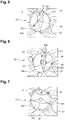
- Fig. 3 and 4 illustrate the upper portion of the internal combustion engine system 100 shown in Fig. 2 in a first embodiment of the invention.
- the mixing unit 30 comprises a four-way valve comprising a housing 37 defining an internal chamber 38.
- the internal chamber 38 having a first portion 38a in fluid communication with the first inlet 31 and the first outlet 33 of the four-way valve 30 and a second portion 38b in fluid communication with the second inlet 32 and the second outlet 34 of the four-way valve 30, the first and second portions 38a, 38b being separated by a central opening 38c.
- the four-way valve 30 further comprises a flap 39 including a central hub 39c connected to a first 39a and a second 39b symmetrical wings.
- the flap 39 is pivotally connected to the housing 37 around a flap axis 39c that is substantially aligned with the central opening 38c.
- the flap axis 39c is coaxial to a housing axis 37c located at the center of the four-way valve housing 37.
- the wings 39a, 39b extend in a plane that is off-centered with respect to the flap axis 39d.
- the wings 39a, 39b of the flap 39 can be respectively in contact with seats 37a, 37b to allow a non-restricted flow of gas between the first and second portions 38a, 38b in both bottom and top parts of the internal chamber 38.
- the wings 39a, 39b of the flap 39 are controlled to reach a position allowing a non-restricted gas flow between the first and second portions 38a, 38b in both bottom and top parts of the internal chamber 38 without requiring seats.
- This configuration of the valve 30 corresponds to the nominal operating mode i) of the system 100 in which a mix of exhaust gas and fresh air is supplied to the cylinders 4 of the first and second groups of cylinders 4a, 4b.
- the wings 39a, 39b of the flap 39 are respectively in contact with seats 37c, 37d.
- the fresh air supplied by the air inlet line 10 is guided through the first group of cylinders 4a only.
- the intake of fresh air for the second group of cylinders 4b is thus controlled to be zero or almost zero.
- the entire flow of exhaust gas supplied by the EGR line 20 is guided through the first group of cylinders 4b only ( Figure 6 ).
- This second configuration of the valve 30 will thus lead to an increase of the overall temperature of the whole exhaust gas when the cylinders 4 of the first group of cylinders 4a are controlled to be active and the cylinders 4 of the second group of cylinders 4b are controlled to be inactive.
- no flow of exhaust gas supplied by the EGR line 20 is guided through the first group of cylinders 4b ( Figure 5 ).
- the engine operation is simplified and the exhaust gas temperature is maximized to ensure the minimum air flow going through the inactive group of cylinders.
- the flap 39 can rotate around the flap axis 39c by an angle of few degrees to reach intermediate positions leading to a control of the flow of fresh air and exhaust gas guided through the first 4aand/or the second cylinder 4b.
- the wings 39a, 39b of the flap 39 are not in contact with seats 38a, 38b, 37c, 37d.
- the flap 39 has rotated clockwise around the flap axis 39c with an angle of 45° when compared to Figures 5 and 6 .
- This example corresponds to a third configuration of the valve 30 wherein the fresh air supplied by the air inlet line 10 is guided through the first group of cylinders 4b only. The intake of fresh air for the first group of cylinders 4a is thus controlled to be zero or almost zero.
- the main flow of exhaust gas can be supplied by the EGR line 20 is guided through the first group of cylinders 4a.
- This third configuration of the valve 30 will thus lead to an increase of the overall temperature of the whole exhaust gas when the cylinders 4 of the first group of cylinders 4b are controlled to be active and the cylinders 4 of the second group of cylinders 4a are controlled to be inactive.
- the flap 39 can rotate around the flap axis 39c by an angle of few degrees depending on the engine operating conditions to decrease fresh air intake pulsation and/or exhaust gas pulsation.
- the method for operating the internal combustion engine system comprising the step A) of selecting an operating mode of the internal combustion engine system, said operating mode being selecting between:
- the controller 40 receives the selected operative mode via an electronic control unit (ECU). Then, in a step B), the controller 40 controls the four-way-valve 30 depending on the operating mode selected in step A) to reach a configuration selected from:
- the internal combustion engine system improves the control of the flow of fresh air and exhaust gas supplied to the engine cylinders.
- the symmetry of pressure drops for fresh air and exhaust gas and the mixing of fresh air and exhaust gas is performed in more equal proportion.
- the invention provides a specific design of the four-way valve to ensure a better control of the flow pattern of fresh air and exhaust gas.
Landscapes
- Engineering & Computer Science (AREA)
- Chemical & Material Sciences (AREA)
- General Engineering & Computer Science (AREA)
- Mechanical Engineering (AREA)
- Combustion & Propulsion (AREA)
- Chemical Kinetics & Catalysis (AREA)
- Output Control And Ontrol Of Special Type Engine (AREA)
- Control Of Throttle Valves Provided In The Intake System Or In The Exhaust System (AREA)
- Exhaust-Gas Circulating Devices (AREA)
Priority Applications (5)
| Application Number | Priority Date | Filing Date | Title |
|---|---|---|---|
| EP21169650.5A EP4080035A1 (de) | 2021-04-21 | 2021-04-21 | Verbrennungsmotorsystem |
| US17/659,752 US11536227B2 (en) | 2021-04-21 | 2022-04-19 | Internal combustion engine system |
| JP2022069558A JP2022166843A (ja) | 2021-04-21 | 2022-04-20 | 内燃機関システム |
| CN202210415117.0A CN115217689A (zh) | 2021-04-21 | 2022-04-20 | 内燃机系统 |
| EP22168941.7A EP4080036B1 (de) | 2021-04-21 | 2022-04-20 | Verbrennungsmotorsystem |
Applications Claiming Priority (1)
| Application Number | Priority Date | Filing Date | Title |
|---|---|---|---|
| EP21169650.5A EP4080035A1 (de) | 2021-04-21 | 2021-04-21 | Verbrennungsmotorsystem |
Publications (1)
| Publication Number | Publication Date |
|---|---|
| EP4080035A1 true EP4080035A1 (de) | 2022-10-26 |
Family
ID=75625490
Family Applications (2)
| Application Number | Title | Priority Date | Filing Date |
|---|---|---|---|
| EP21169650.5A Withdrawn EP4080035A1 (de) | 2021-04-21 | 2021-04-21 | Verbrennungsmotorsystem |
| EP22168941.7A Active EP4080036B1 (de) | 2021-04-21 | 2022-04-20 | Verbrennungsmotorsystem |
Family Applications After (1)
| Application Number | Title | Priority Date | Filing Date |
|---|---|---|---|
| EP22168941.7A Active EP4080036B1 (de) | 2021-04-21 | 2022-04-20 | Verbrennungsmotorsystem |
Country Status (4)
| Country | Link |
|---|---|
| US (1) | US11536227B2 (de) |
| EP (2) | EP4080035A1 (de) |
| JP (1) | JP2022166843A (de) |
| CN (1) | CN115217689A (de) |
Families Citing this family (2)
| Publication number | Priority date | Publication date | Assignee | Title |
|---|---|---|---|---|
| US11761408B2 (en) * | 2019-10-23 | 2023-09-19 | Volvo Truck Corporation | Internal combustion engine system operable in at least two operating modes |
| CN116877281B (zh) * | 2022-12-05 | 2026-02-10 | 中船动力镇江有限公司 | 大功率船用柴油机辅助紧急停车装置 |
Citations (9)
| Publication number | Priority date | Publication date | Assignee | Title |
|---|---|---|---|---|
| US6023929A (en) * | 1995-08-26 | 2000-02-15 | Ford Global Technologies, Inc. | Engine with cylinder deactivation |
| EP1612393A1 (de) * | 2004-06-30 | 2006-01-04 | Ford Global Technologies, LLC | Verfahren und Vorrichtung zum Betreiben einer mehrzylindrigen fremdgezündeten Viertakt-Brennkraftmaschine mit Zylinderabschaltung |
| US20060213189A1 (en) * | 2003-06-18 | 2006-09-28 | Allansson Eive Tord R | Treatment of nox sorber regeneration gas |
| EP2295769A1 (de) * | 2009-08-14 | 2011-03-16 | International Engine Intellectual Property Company, LLC. | Abluftsystem für Motorbremsen |
| EP2700851A1 (de) * | 2012-08-24 | 2014-02-26 | Eberspächer Exhaust Technology GmbH & Co. KG | Vier-Wege-Abgasventil |
| WO2015004497A1 (en) * | 2013-07-10 | 2015-01-15 | Renault Trucks | Turbocharged engine arrangement with exhaust gases recirculation installations and rotary flow control valve |
| US20160298557A1 (en) * | 2013-11-29 | 2016-10-13 | Volvo Construction Equipment Ab | An internal combustion engine and a method for controlling an internal combustion engine |
| US10480377B2 (en) * | 2014-08-22 | 2019-11-19 | Cummins Inc. | System and method to improve aftertreatment in an internal combustion engine |
| WO2021078379A1 (en) * | 2019-10-23 | 2021-04-29 | Volvo Truck Corporation | Internal combustion engine system operable in at least two operating modes |
Family Cites Families (17)
| Publication number | Priority date | Publication date | Assignee | Title |
|---|---|---|---|---|
| JPS5853182B2 (ja) * | 1979-05-07 | 1983-11-28 | 日産自動車株式会社 | 気筒数制御エンジンの排気還流装置 |
| US6484703B1 (en) * | 2001-05-08 | 2002-11-26 | Caterpillar Inc. | EGR/bleed air diverter valve |
| US6698717B1 (en) | 2002-10-24 | 2004-03-02 | Honeywell International Inc. | Modified butterfly valve and assembly |
| DE102004021212A1 (de) | 2004-04-29 | 2005-11-24 | Volkswagen Ag | Vorrichtung zur Abgasrückführung |
| FR2926113A1 (fr) | 2008-01-03 | 2009-07-10 | Valeo Sys Controle Moteur Sas | Boucle egr d'un moteur a combustion interne d'un vehicule automobile |
| JP4553023B2 (ja) | 2008-03-21 | 2010-09-29 | 株式会社デンソー | 排気ガス切替弁 |
| US8448626B2 (en) * | 2008-08-13 | 2013-05-28 | International Engine Intellectual Property Company, Llc | Exhaust system for engine braking |
| ITBO20100210A1 (it) | 2010-04-07 | 2011-10-08 | Magneti Marelli Spa | Dispositivo miscelatore monovalvola per un sistema egr di bassa pressione di un motore a combustione interna |
| US9835065B2 (en) * | 2011-10-03 | 2017-12-05 | Volvo Technology Corporation | Internal combustion engine system and method for increasing the temperature in at least one part of the internal combustion engine system |
| DE102012103311B4 (de) | 2012-04-17 | 2014-05-15 | Pierburg Gmbh | Ventilvorrichtung für eine Verbrennungskraftmaschine |
| US20140102429A1 (en) | 2012-10-12 | 2014-04-17 | GM Global Technology Operations LLC | Inlet manifold with dual port egr |
| DE102013011587A1 (de) * | 2013-07-10 | 2015-01-15 | Daimler Ag | Verbrennungskraftmaschine für einen Kraftwagen sowie Verfahren zum Betreiben einer solchen Verbrennungskraftmaschine |
| DE102016203823B3 (de) * | 2016-03-09 | 2017-08-24 | Ford Global Technologies, Llc | Verfahren zum Betreiben einer abgasturboaufgeladenen Brennkraftmaschine mit Teilabschaltung |
| JP6698419B2 (ja) | 2016-05-06 | 2020-05-27 | 愛三工業株式会社 | 排気還流弁 |
| WO2019078873A1 (en) | 2017-10-19 | 2019-04-25 | B & D Technologies, LLC | CLIMATIC CONTROL SYSTEM FOR NON-CLOSED MOWER |
| KR102394577B1 (ko) * | 2017-10-27 | 2022-05-04 | 현대자동차 주식회사 | 엔진 시스템 |
| US10513992B1 (en) * | 2018-12-21 | 2019-12-24 | Southwest Research Institute | Internal combustion engine having dedicated EGR cylinder(s) with split intake and cylinder deactivation at low loads |
-
2021
- 2021-04-21 EP EP21169650.5A patent/EP4080035A1/de not_active Withdrawn
-
2022
- 2022-04-19 US US17/659,752 patent/US11536227B2/en active Active
- 2022-04-20 JP JP2022069558A patent/JP2022166843A/ja active Pending
- 2022-04-20 EP EP22168941.7A patent/EP4080036B1/de active Active
- 2022-04-20 CN CN202210415117.0A patent/CN115217689A/zh active Pending
Patent Citations (9)
| Publication number | Priority date | Publication date | Assignee | Title |
|---|---|---|---|---|
| US6023929A (en) * | 1995-08-26 | 2000-02-15 | Ford Global Technologies, Inc. | Engine with cylinder deactivation |
| US20060213189A1 (en) * | 2003-06-18 | 2006-09-28 | Allansson Eive Tord R | Treatment of nox sorber regeneration gas |
| EP1612393A1 (de) * | 2004-06-30 | 2006-01-04 | Ford Global Technologies, LLC | Verfahren und Vorrichtung zum Betreiben einer mehrzylindrigen fremdgezündeten Viertakt-Brennkraftmaschine mit Zylinderabschaltung |
| EP2295769A1 (de) * | 2009-08-14 | 2011-03-16 | International Engine Intellectual Property Company, LLC. | Abluftsystem für Motorbremsen |
| EP2700851A1 (de) * | 2012-08-24 | 2014-02-26 | Eberspächer Exhaust Technology GmbH & Co. KG | Vier-Wege-Abgasventil |
| WO2015004497A1 (en) * | 2013-07-10 | 2015-01-15 | Renault Trucks | Turbocharged engine arrangement with exhaust gases recirculation installations and rotary flow control valve |
| US20160298557A1 (en) * | 2013-11-29 | 2016-10-13 | Volvo Construction Equipment Ab | An internal combustion engine and a method for controlling an internal combustion engine |
| US10480377B2 (en) * | 2014-08-22 | 2019-11-19 | Cummins Inc. | System and method to improve aftertreatment in an internal combustion engine |
| WO2021078379A1 (en) * | 2019-10-23 | 2021-04-29 | Volvo Truck Corporation | Internal combustion engine system operable in at least two operating modes |
Also Published As
| Publication number | Publication date |
|---|---|
| JP2022166843A (ja) | 2022-11-02 |
| EP4080036B1 (de) | 2024-07-31 |
| US11536227B2 (en) | 2022-12-27 |
| US20220341380A1 (en) | 2022-10-27 |
| EP4080036C0 (de) | 2024-07-31 |
| EP4080036A1 (de) | 2022-10-26 |
| CN115217689A (zh) | 2022-10-21 |
Similar Documents
| Publication | Publication Date | Title |
|---|---|---|
| US7509805B2 (en) | Control of exhaust to a turbo of internal combustion engine | |
| US6205785B1 (en) | Exhaust gas recirculation system | |
| EP1957766B1 (de) | Turbogeladenes motorsystem und betriebsverfahren dafür | |
| EP3559431B1 (de) | Verfahren zur steuerung eines verbrennungsmotors | |
| US9051903B2 (en) | NOx emission control using large volume EGR | |
| EP4080036A1 (de) | Verbrennungsmotorsystem | |
| CN103717855B (zh) | 用于机动车的内燃发动机 | |
| US20220235725A1 (en) | Cylinder head with integrated catalyst | |
| EP4048877B1 (de) | In mindestens zwei betriebsarten betreibbares verbrennungsmotorsystem | |
| US11512672B2 (en) | Internal combustion engine system operable in at least two operating modes | |
| EP3645846B1 (de) | Verfahren für ein fahrzeugsystem | |
| US11378027B2 (en) | Method for controlling an internal combustion engine | |
| EP3473838A1 (de) | Motorsystem | |
| EP3889407A1 (de) | Aufgeladener motor und fahrzeug mit einem aufgeladenen motor | |
| JP7472846B2 (ja) | エンジンシステム | |
| EP3168444B1 (de) | Verbrennungsmotor und verfahren zur steuerung davon | |
| CN118775053A (zh) | V型发动机以及车辆 | |
| US20120067032A1 (en) | Particulate filter regeneration |
Legal Events
| Date | Code | Title | Description |
|---|---|---|---|
| PUAI | Public reference made under article 153(3) epc to a published international application that has entered the european phase |
Free format text: ORIGINAL CODE: 0009012 |
|
| STAA | Information on the status of an ep patent application or granted ep patent |
Free format text: STATUS: THE APPLICATION HAS BEEN PUBLISHED |
|
| AK | Designated contracting states |
Kind code of ref document: A1 Designated state(s): AL AT BE BG CH CY CZ DE DK EE ES FI FR GB GR HR HU IE IS IT LI LT LU LV MC MK MT NL NO PL PT RO RS SE SI SK SM TR |
|
| STAA | Information on the status of an ep patent application or granted ep patent |
Free format text: STATUS: THE APPLICATION IS DEEMED TO BE WITHDRAWN |
|
| 18D | Application deemed to be withdrawn |
Effective date: 20230427 |