EP4080040A1 - Turbine éolienne avec axe vertical de rotation du rotor - Google Patents
Turbine éolienne avec axe vertical de rotation du rotor Download PDFInfo
- Publication number
- EP4080040A1 EP4080040A1 EP19956305.7A EP19956305A EP4080040A1 EP 4080040 A1 EP4080040 A1 EP 4080040A1 EP 19956305 A EP19956305 A EP 19956305A EP 4080040 A1 EP4080040 A1 EP 4080040A1
- Authority
- EP
- European Patent Office
- Prior art keywords
- rotor
- blades
- stator
- diffuser
- wind turbine
- Prior art date
- Legal status (The legal status is an assumption and is not a legal conclusion. Google has not performed a legal analysis and makes no representation as to the accuracy of the status listed.)
- Granted
Links
Images


Classifications
-
- F—MECHANICAL ENGINEERING; LIGHTING; HEATING; WEAPONS; BLASTING
- F03—MACHINES OR ENGINES FOR LIQUIDS; WIND, SPRING, OR WEIGHT MOTORS; PRODUCING MECHANICAL POWER OR A REACTIVE PROPULSIVE THRUST, NOT OTHERWISE PROVIDED FOR
- F03D—WIND MOTORS
- F03D3/00—Wind motors with rotation axis substantially perpendicular to the air flow entering the rotor
- F03D3/04—Wind motors with rotation axis substantially perpendicular to the air flow entering the rotor having stationary wind-guiding means, e.g. with shrouds or channels
- F03D3/0427—Wind motors with rotation axis substantially perpendicular to the air flow entering the rotor having stationary wind-guiding means, e.g. with shrouds or channels with converging inlets, i.e. the guiding means intercepting an area greater than the effective rotor area
-
- F—MECHANICAL ENGINEERING; LIGHTING; HEATING; WEAPONS; BLASTING
- F03—MACHINES OR ENGINES FOR LIQUIDS; WIND, SPRING, OR WEIGHT MOTORS; PRODUCING MECHANICAL POWER OR A REACTIVE PROPULSIVE THRUST, NOT OTHERWISE PROVIDED FOR
- F03D—WIND MOTORS
- F03D3/00—Wind motors with rotation axis substantially perpendicular to the air flow entering the rotor
- F03D3/005—Wind motors with rotation axis substantially perpendicular to the air flow entering the rotor the axis being vertical
- F03D3/009—Wind motors with rotation axis substantially perpendicular to the air flow entering the rotor the axis being vertical of the drag type, e.g. Savonius
-
- F—MECHANICAL ENGINEERING; LIGHTING; HEATING; WEAPONS; BLASTING
- F03—MACHINES OR ENGINES FOR LIQUIDS; WIND, SPRING, OR WEIGHT MOTORS; PRODUCING MECHANICAL POWER OR A REACTIVE PROPULSIVE THRUST, NOT OTHERWISE PROVIDED FOR
- F03D—WIND MOTORS
- F03D3/00—Wind motors with rotation axis substantially perpendicular to the air flow entering the rotor
- F03D3/06—Rotors
- F03D3/061—Rotors characterised by their aerodynamic shape, e.g. aerofoil profiles
-
- F—MECHANICAL ENGINEERING; LIGHTING; HEATING; WEAPONS; BLASTING
- F03—MACHINES OR ENGINES FOR LIQUIDS; WIND, SPRING, OR WEIGHT MOTORS; PRODUCING MECHANICAL POWER OR A REACTIVE PROPULSIVE THRUST, NOT OTHERWISE PROVIDED FOR
- F03D—WIND MOTORS
- F03D3/00—Wind motors with rotation axis substantially perpendicular to the air flow entering the rotor
- F03D3/06—Rotors
- F03D3/062—Rotors characterised by their construction elements
- F03D3/064—Fixing wind engaging parts to rest of rotor
-
- F—MECHANICAL ENGINEERING; LIGHTING; HEATING; WEAPONS; BLASTING
- F05—INDEXING SCHEMES RELATING TO ENGINES OR PUMPS IN VARIOUS SUBCLASSES OF CLASSES F01-F04
- F05B—INDEXING SCHEME RELATING TO WIND, SPRING, WEIGHT, INERTIA OR LIKE MOTORS, TO MACHINES OR ENGINES FOR LIQUIDS COVERED BY SUBCLASSES F03B, F03D AND F03G
- F05B2240/00—Components
- F05B2240/10—Stators
- F05B2240/12—Fluid guiding means, e.g. vanes
-
- F—MECHANICAL ENGINEERING; LIGHTING; HEATING; WEAPONS; BLASTING
- F05—INDEXING SCHEMES RELATING TO ENGINES OR PUMPS IN VARIOUS SUBCLASSES OF CLASSES F01-F04
- F05B—INDEXING SCHEME RELATING TO WIND, SPRING, WEIGHT, INERTIA OR LIKE MOTORS, TO MACHINES OR ENGINES FOR LIQUIDS COVERED BY SUBCLASSES F03B, F03D AND F03G
- F05B2240/00—Components
- F05B2240/10—Stators
- F05B2240/13—Stators to collect or cause flow towards or away from turbines
-
- F—MECHANICAL ENGINEERING; LIGHTING; HEATING; WEAPONS; BLASTING
- F05—INDEXING SCHEMES RELATING TO ENGINES OR PUMPS IN VARIOUS SUBCLASSES OF CLASSES F01-F04
- F05B—INDEXING SCHEME RELATING TO WIND, SPRING, WEIGHT, INERTIA OR LIKE MOTORS, TO MACHINES OR ENGINES FOR LIQUIDS COVERED BY SUBCLASSES F03B, F03D AND F03G
- F05B2250/00—Geometry
- F05B2250/10—Geometry two-dimensional
- F05B2250/17—Geometry two-dimensional hyperbolic
-
- F—MECHANICAL ENGINEERING; LIGHTING; HEATING; WEAPONS; BLASTING
- F05—INDEXING SCHEMES RELATING TO ENGINES OR PUMPS IN VARIOUS SUBCLASSES OF CLASSES F01-F04
- F05B—INDEXING SCHEME RELATING TO WIND, SPRING, WEIGHT, INERTIA OR LIKE MOTORS, TO MACHINES OR ENGINES FOR LIQUIDS COVERED BY SUBCLASSES F03B, F03D AND F03G
- F05B2250/00—Geometry
- F05B2250/20—Geometry three-dimensional
- F05B2250/27—Geometry three-dimensional hyperboloidal
-
- F—MECHANICAL ENGINEERING; LIGHTING; HEATING; WEAPONS; BLASTING
- F05—INDEXING SCHEMES RELATING TO ENGINES OR PUMPS IN VARIOUS SUBCLASSES OF CLASSES F01-F04
- F05B—INDEXING SCHEME RELATING TO WIND, SPRING, WEIGHT, INERTIA OR LIKE MOTORS, TO MACHINES OR ENGINES FOR LIQUIDS COVERED BY SUBCLASSES F03B, F03D AND F03G
- F05B2250/00—Geometry
- F05B2250/50—Inlet or outlet
- F05B2250/502—Outlet
-
- Y—GENERAL TAGGING OF NEW TECHNOLOGICAL DEVELOPMENTS; GENERAL TAGGING OF CROSS-SECTIONAL TECHNOLOGIES SPANNING OVER SEVERAL SECTIONS OF THE IPC; TECHNICAL SUBJECTS COVERED BY FORMER USPC CROSS-REFERENCE ART COLLECTIONS [XRACs] AND DIGESTS
- Y02—TECHNOLOGIES OR APPLICATIONS FOR MITIGATION OR ADAPTATION AGAINST CLIMATE CHANGE
- Y02E—REDUCTION OF GREENHOUSE GAS [GHG] EMISSIONS, RELATED TO ENERGY GENERATION, TRANSMISSION OR DISTRIBUTION
- Y02E10/00—Energy generation through renewable energy sources
- Y02E10/70—Wind energy
- Y02E10/74—Wind turbines with rotation axis perpendicular to the wind direction
Definitions
- the invention relates to wind energy, and specifically, to wind motors having a vertical axis of rotation of the rotor relative to the horizon, and can be used to convert the energy of the air flow into a rotary motion, transmitted to an electric generator, a pump, or a different rotating mechanism.
- a wind turbine which comprises a rotor placed vertically with the possibility of rotation inside a housing and provided with blades [patent DE 3636248, IPC F03D 9/00, publ. 05.05.1988 ].
- the wind turbine is installed inside a pipe and operates in an upward flow of air using a chimney effect.
- FIG. 1 Another known wind turbine [patent RU 2286477, IPC F03D 1/02, publ. 27.10.2006 ] comprises a rotor placed inside a stationary body (stator) with the possibility of rotation therewithin.
- the rotor consists of a shaft with radial-type turbine blades installed vertically along the circumference at a given distance from the center and attached to the rotor shaft by means of brackets (cross-pieces).
- the stator is made in the form of a guiding apparatus, consisting of vertically arranged guide vanes mounted at an acute angle to the outer edge of the radial-type turbine blades, which form external wind flow channels located tangentially with respect to an inner circumference of the system.
- a lower part of the rotor is made in the form of an axial turbine.
- the shaft is equipped with axial rotor blades designed to operate in the flow of air coming out of the guide vanes.
- Additional guide vanes are installed in the lower part of the body and are arranged radially inside a shell.
- a lower end of the rotor rests on a fairing, which is rigidly attached to the ends of the vanes of the guiding apparatus.
- An upper part of the shell is fastened to the body, while a lower part is secured to an upper part of the hollow body (upward-pull pipe) with a confuser installed thereon.
- Air supply windows are arranged in the lower part of the hollow body.
- the wind turbine system operates by using the energy of horizontal wind flows, as well as the energy of upward flows developing in the hollow body provided with the confuser.
- the upward flows of air are not picked up by the horizontal ones. Instead, they partially block such horizontal flows and slow them down.
- a chaotic uncontrolled mixing of two practically perpendicular flows results in the formation of a significant and uncontrolled turbulence in the upper zone, which therefore reduces the system efficiency.
- This "counteraction" increases as the force of the horizontal wind flows becomes greater.
- a wind turbine system [patent RU 2488019, IPC F03D 3/06, F03D 3/04, publ. 20.07.2013 ], which comprises a stator with upper and lower bases interconnected by vertical inward-oriented guide vanes. A rotor provided with longitudinal blades is placed in the stator. A body of the rotor is made in the form of a hollow cone tapering upward. Rotor blades are installed on its outer surface and are oriented at an angle to an axis of symmetry of the rotor. Platelike cross-pieces are installed in an inner cavity of the rotor, connecting it with upper and lower half-axles of rotation.
- the lower base of the stator is configured to allow air to enter the rotor.
- the upper base of the stator has a conical part directed and tapering towards the lower base, and is provided with an axial opening, a diameter of which is larger than an upper diameter of the rotor cone, so that an annular gap is formed between them.
- An additional impeller is installed on the upper half-axle of the rotor extending into the conical part of the upper base of the stator.
- the lower half-axle of the rotor is mounted on the lower base of the stator.
- the upper half-axle is connected to the upper base by means of radial ribs installed inside the conical part of the upper base.
- a lower confuser with the blades attached thereto is installed on the lower base.
- the wind turbine system according to patent RU 2488019 (2013 ) has following disadvantages, which reduce its performance efficiency.
- the conical part of the upper base of the stator interferes with the operation of the entire system by shielding a low-pressure zone created under the upper impeller from the outer blades of the rotor.
- a rather small diameter of the upper impeller reduces the velocity of the upward flow.
- the system is not protected from atmospheric precipitations.
- the objective of the invention is to increase the performance efficiency of the wind turbine having a vertical axis of rotation of the rotor without changing the geometric dimensions.
- the technical result consists in increasing the power of the wind turbine by creating an enhanced air flow inside thereof.
- a wind turbine with a vertical axis of rotation of the rotor which comprises a stator with lower and upper bases interconnected by vertical guide vanes of the stator, a rotor body made in the form of a hollow truncated cone tapering upward, rotor blades installed on an outer surface of the rotor body, upper and lower half-axes of rotation of the rotor installed in upper and lower supports, respectively, an upper cross-piece, an upper impeller, a lower confuser with blades, wherein, according to the invention, the upper impeller is secured inside an upper part of the rotor body, a diffuser is installed above the stator and is made in the form of two spaced biconvex discs, a lower disc of the diffuser being rigidly connected to an upper disc of the diffuser, while serving as the upper base of the stator, the stator vanes have a curved surface and are oriented outward, the rotor body has a curved surface with the upper part thereof being secured
- the surface of the rotor body and the rotor blades have a hyperbolic shape.
- stator vanes are configured to enable a change in an angle of inclination relative to the vertical axis of the stator.
- An increase in power of the wind turbine is achieved by the fact that an upward vortex flow is created inside and outside the rotor, which redirects the horizontal wind flows inside the system, including those in a wind shadow area, into a vertical flow with a swirling effect.
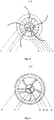
- a wind turbine with a vertical axis of rotation of the rotor comprises a stationary stator 1 provided with a lower base 2 and an upper base 3.
- the bases 2 and 3 are interconnected by vertical guide vanes 4 of the stator, oriented outward and configured to rotate relative to an axis 5.
- a rotor 6 is arranged inside the stator 1 and has a common axis of symmetry therewith.
- a rotor body 7 is made in the form of a hollow cone tapering upward, which has a curved surface. It is preferable that the surface of the rotor body has a hyperbolic shape.
- Longitudinal blades 8 are installed on an outer surface of the rotor body 7 and are made in the form of curved ribs.
- the blades 8 are oriented at an angle to the axis of symmetry of the rotor. It is preferable that the surface of the rotor blades has a hyperbolic shape.
- a diffuser 9 is installed above the stator 1 and is made in the form of two spaced biconvex discs, a lower disc 10 of which being rigidly connected to an upper disc 11 and serving as the upper base 2 of the stator.
- the connection between the diffuser discs can be achieved, for example, by using studs 12.
- the distance between the diffuser discs is selected to provide lower air pressure above the upper impeller of the rotor.
- Blades 15 of the upper impeller are used to secure the upper part of the rotor 6 to an upper half-axle of rotation 16 of the rotor, an upper support 17 of which is attached to the upper base 2 by means of an upper cross-piece 18.
- Blades 20 of the lower impeller 14 of the rotor are used to connect the rotor 6 with a lower half-axle of rotation 19.
- a lower support 21 of the rotor is secured at the top of a confuser 22 provided with blades 23.
- a cavity 24 of the lower disc 10 of the diffuser additionally comprises a rotor fan 25, blades 26 of which are wrapped around the upper part of the outer surface of the rotor body 7.
- a blade spacing of the upper impeller 13 is selected to be greater than a blade spacing of the fan 25 in order to equalize the flow velocities inside and outside the rotor body due to different angular velocities of the blades in the center of the rotor and the periphery thereof.
- the transmission of the rotary motion of the rotor, for example, to an electric generator or a pump, is realized by means of the lower half-axle.
- the wind turbine with a vertical axis of rotation of the rotor operates as follows.
- a horizontal air flow hits the stator vanes 4.
- a part of the flow impacting the outer parts of the stator vanes is deflected outward by the vanes to bypass the rotor 6.
- Another part of the air flow impacts the inner surfaces of the stator vanes 4, becomes accelerated by them and impacts the rotor blades 8.
- an upward flow is formed along the outer surface of the rotor concurrently with the creation of a rotation torque for the entire rotor structure. This external upward flow impacts the blades of the fan 25 of the rotor, thus creating an additional rotor torque.
- the resulting decrease in pressure causes the air flow from below to enter the confuser 22, where the vertical air flow velocity increases, the flow is swirled due to the curvilinear shape of the confuser blades 23, and an upward flow entering the rotor body 7 is formed.
- the internal air flow sequentially impacts the lower impeller 14 and then the upper impeller 13, therefore increasing the rotor torque.
- the entire structure as a whole creates the motion of the enhanced air flow inside the wind turbine, including a wind shadow area, due to acceleration of the air flow by the confuser, internal impellers 13 and 14 of the rotor, rotor blades 8, as well as creation of the area of low air pressure by the fan 25 and diffuser 9.
- the upper disc 11 of the diffuser protects the structure from atmospheric precipitation.
- the proposed wind turbine with a vertical axis of rotation of the rotor is characterized by a low sound emission due to the absence of planes moving in parallel with different speeds.
Landscapes
- Engineering & Computer Science (AREA)
- Life Sciences & Earth Sciences (AREA)
- Sustainable Development (AREA)
- Sustainable Energy (AREA)
- Chemical & Material Sciences (AREA)
- Combustion & Propulsion (AREA)
- Mechanical Engineering (AREA)
- General Engineering & Computer Science (AREA)
- Physics & Mathematics (AREA)
- Fluid Mechanics (AREA)
- Wind Motors (AREA)
Applications Claiming Priority (1)
| Application Number | Priority Date | Filing Date | Title |
|---|---|---|---|
| PCT/RU2019/000952 WO2021125994A1 (fr) | 2019-12-16 | 2019-12-16 | Turbine éolienne avec axe vertical de rotation du rotor |
Publications (3)
| Publication Number | Publication Date |
|---|---|
| EP4080040A1 true EP4080040A1 (fr) | 2022-10-26 |
| EP4080040A4 EP4080040A4 (fr) | 2023-09-13 |
| EP4080040B1 EP4080040B1 (fr) | 2026-04-22 |
Family
ID=76477633
Family Applications (1)
| Application Number | Title | Priority Date | Filing Date |
|---|---|---|---|
| EP19956305.7A Active EP4080040B1 (fr) | 2019-12-16 | 2019-12-16 | Turbine éolienne à axe vertical |
Country Status (5)
| Country | Link |
|---|---|
| US (1) | US11994103B2 (fr) |
| EP (1) | EP4080040B1 (fr) |
| AU (1) | AU2019479010B2 (fr) |
| CA (1) | CA3164675A1 (fr) |
| WO (1) | WO2021125994A1 (fr) |
Families Citing this family (3)
| Publication number | Priority date | Publication date | Assignee | Title |
|---|---|---|---|---|
| CN113638846B (zh) * | 2021-10-18 | 2021-12-24 | 山西丰秦源新能源开发有限公司 | 微风聚能风力发电装置 |
| IT202200000215U1 (it) * | 2022-01-24 | 2023-07-24 | Giuseppe Cosentino | Pala eolica ad asse verticale |
| US12338791B1 (en) * | 2023-07-03 | 2025-06-24 | Halcium Energy Inc | Wind turbines |
Family Cites Families (16)
| Publication number | Priority date | Publication date | Assignee | Title |
|---|---|---|---|---|
| US1519447A (en) * | 1923-01-18 | 1924-12-16 | Fortier-Beaulieu Paul Adolphe | Aerial turbine with vertical axis and helical-centripetal circulation |
| SU408049A1 (ru) | 1971-07-29 | 1973-12-10 | Всесоюзный научно исследовательскпй институт охраны труда ВЦСПС Тбилиси | Ветродвигатель |
| US4309146A (en) * | 1980-03-12 | 1982-01-05 | The United States Of America As Represented By The Administrator Of The National Aeronautics And Space Administration | Amplified wind turbine apparatus |
| ES8301330A1 (es) * | 1980-07-24 | 1982-12-01 | Central Energetic Ciclonic | Sistema para la obtencion de energia mediante flujos simili-lares a los que conforman un ciclon o un anticiclon natural |
| US4508973A (en) * | 1984-05-25 | 1985-04-02 | Payne James M | Wind turbine electric generator |
| DE3636248A1 (de) | 1986-10-24 | 1988-05-05 | Eggert Buelk | Aufwindkraftwerk |
| ES2166663B1 (es) * | 1999-05-20 | 2003-12-01 | Tryp Multiserv S L | Torre de conversion ciclonica o anticiclonica. |
| CN1249340C (zh) | 2001-04-12 | 2006-04-05 | 黄建文 | 集风式风力发电方法与设备 |
| US6740989B2 (en) | 2002-08-21 | 2004-05-25 | Pacifex Management Inc. | Vertical axis wind turbine |
| RU2286477C2 (ru) | 2004-11-23 | 2006-10-27 | Дальневосточный государственный технический университет | Ветротурбинная установка |
| EP2108820A2 (fr) * | 2008-04-09 | 2009-10-14 | Proyectos de ingenieria tecnologica, S.A. | Éolienne |
| CN102996359A (zh) | 2011-09-14 | 2013-03-27 | 周登荣 | 自然能源蓄能发电方法及其发电系统 |
| RU2488019C1 (ru) * | 2011-11-29 | 2013-07-20 | Анатолий Викторович Леошко | Ветротурбинная установка |
| RU117522U1 (ru) | 2011-12-05 | 2012-06-27 | Анатолий Викторович Леошко | Ветротурбинная установка |
| CN107250531A (zh) * | 2014-08-12 | 2017-10-13 | 蒋素芳 | 一种风力发电装置和系统 |
| US10612515B2 (en) * | 2015-06-25 | 2020-04-07 | Dme Wind Energy Corporation | Vertical axis wind turbine |
-
2019
- 2019-12-16 EP EP19956305.7A patent/EP4080040B1/fr active Active
- 2019-12-16 AU AU2019479010A patent/AU2019479010B2/en active Active
- 2019-12-16 US US17/784,985 patent/US11994103B2/en active Active
- 2019-12-16 WO PCT/RU2019/000952 patent/WO2021125994A1/fr not_active Ceased
- 2019-12-16 CA CA3164675A patent/CA3164675A1/fr active Pending
Also Published As
| Publication number | Publication date |
|---|---|
| EP4080040B1 (fr) | 2026-04-22 |
| EP4080040A4 (fr) | 2023-09-13 |
| WO2021125994A1 (fr) | 2021-06-24 |
| CA3164675A1 (fr) | 2021-06-24 |
| AU2019479010A1 (en) | 2022-07-21 |
| AU2019479010B2 (en) | 2024-09-12 |
| US11994103B2 (en) | 2024-05-28 |
| US20230008558A1 (en) | 2023-01-12 |
Similar Documents
| Publication | Publication Date | Title |
|---|---|---|
| CN101103198B (zh) | 全向风轮机 | |
| JP5258774B2 (ja) | 風力発電装置、大気から電力を発生させるための発電機、及び、移動する大気から電力を発生させるための方法 | |
| US7018166B2 (en) | Ducted wind turbine | |
| EP4080040B1 (fr) | Turbine éolienne à axe vertical | |
| US8128337B2 (en) | Omnidirectional vertical-axis wind turbine | |
| KR101368611B1 (ko) | 접선 방향 로터 블레이드를 갖는 경계층 풍력 발전용 터빈 | |
| JPH06507693A (ja) | 並流から有用なエネルギーを発生させるための方法及び装置 | |
| CN107339241B (zh) | 多翼离心风机 | |
| CN107339261B (zh) | 一种强吸力多翼离心风机 | |
| WO2016030821A1 (fr) | Rotor double à trois aubes pour turbine à axe vertical | |
| KR101396137B1 (ko) | 환기풍력을 이용한 발전장치 | |
| KR101336280B1 (ko) | 집풍식 풍력 터빈 발전기 | |
| KR20080077921A (ko) | 풍력 발전기의 회전자 | |
| KR20180044929A (ko) | 로터 회전 수평축을 가진 터널 풍력 터빈 | |
| EP4160002B1 (fr) | Éolienne avec déflecteur | |
| WO2018088929A1 (fr) | Installation à turbine éolienne | |
| RU2787430C1 (ru) | Ветротурбина с вертикальной осью вращения ротора | |
| KR101732145B1 (ko) | 풍력발전장치 | |
| RU2488019C1 (ru) | Ветротурбинная установка | |
| RU117522U1 (ru) | Ветротурбинная установка | |
| EA041796B1 (ru) | Ветротурбина с вертикальной осью вращения ротора | |
| CN113015499B (zh) | 用于牙科预备器械中的转子的反向流制动 | |
| CN104859840A (zh) | 涵道动力装置和飞行器 | |
| CN204895840U (zh) | 涵道动力装置和飞行器 | |
| WO2017081496A1 (fr) | Éolienne de kionas |
Legal Events
| Date | Code | Title | Description |
|---|---|---|---|
| STAA | Information on the status of an ep patent application or granted ep patent |
Free format text: STATUS: THE INTERNATIONAL PUBLICATION HAS BEEN MADE |
|
| PUAI | Public reference made under article 153(3) epc to a published international application that has entered the european phase |
Free format text: ORIGINAL CODE: 0009012 |
|
| STAA | Information on the status of an ep patent application or granted ep patent |
Free format text: STATUS: REQUEST FOR EXAMINATION WAS MADE |
|
| 17P | Request for examination filed |
Effective date: 20220331 |
|
| AK | Designated contracting states |
Kind code of ref document: A1 Designated state(s): AL AT BE BG CH CY CZ DE DK EE ES FI FR GB GR HR HU IE IS IT LI LT LU LV MC MK MT NL NO PL PT RO RS SE SI SK SM TR |
|
| DAV | Request for validation of the european patent (deleted) | ||
| DAX | Request for extension of the european patent (deleted) | ||
| REG | Reference to a national code |
Ref country code: DE Ref legal event code: R079 Free format text: PREVIOUS MAIN CLASS: F03D0003040000 Ipc: F03D0003000000 Ref country code: DE Ref legal event code: R079 Ref document number: 602019084078 Country of ref document: DE Free format text: PREVIOUS MAIN CLASS: F03D0003040000 Ipc: F03D0003000000 |
|
| A4 | Supplementary search report drawn up and despatched |
Effective date: 20230811 |
|
| RIC1 | Information provided on ipc code assigned before grant |
Ipc: F03D 3/06 20060101ALI20230807BHEP Ipc: F03D 3/04 20060101ALI20230807BHEP Ipc: F03D 3/00 20060101AFI20230807BHEP |
|
| GRAP | Despatch of communication of intention to grant a patent |
Free format text: ORIGINAL CODE: EPIDOSNIGR1 |
|
| STAA | Information on the status of an ep patent application or granted ep patent |
Free format text: STATUS: GRANT OF PATENT IS INTENDED |
|
| INTG | Intention to grant announced |
Effective date: 20240705 |
|
| GRAS | Grant fee paid |
Free format text: ORIGINAL CODE: EPIDOSNIGR3 |
|
| GRAA | (expected) grant |
Free format text: ORIGINAL CODE: 0009210 |
|
| STAA | Information on the status of an ep patent application or granted ep patent |
Free format text: STATUS: THE PATENT HAS BEEN GRANTED |
|
| RAP1 | Party data changed (applicant data changed or rights of an application transferred) |
Owner name: TOO "PS CONSULTING" (KZ) |
|
| RIN1 | Information on inventor provided before grant (corrected) |
Inventor name: TOO "PS CONSULTING" (KZ) |
|
| AK | Designated contracting states |
Kind code of ref document: B1 Designated state(s): AL AT BE BG CH CY CZ DE DK EE ES FI FR GB GR HR HU IE IS IT LI LT LU LV MC MK MT NL NO PL PT RO RS SE SI SK SM TR |
|
| REG | Reference to a national code |
Ref country code: CH Ref legal event code: F10 Free format text: ST27 STATUS EVENT CODE: U-0-0-F10-F00 (AS PROVIDED BY THE NATIONAL OFFICE) Effective date: 20260422 Ref country code: GB Ref legal event code: FG4D |
|
| RIN1 | Information on inventor provided before grant (corrected) |
Inventor name: LEOSHKO, ANATOLIJ VIKTOROVICH |