EP4080094B1 - Kugelventil - Google Patents
Kugelventil Download PDFInfo
- Publication number
- EP4080094B1 EP4080094B1 EP21905749.4A EP21905749A EP4080094B1 EP 4080094 B1 EP4080094 B1 EP 4080094B1 EP 21905749 A EP21905749 A EP 21905749A EP 4080094 B1 EP4080094 B1 EP 4080094B1
- Authority
- EP
- European Patent Office
- Prior art keywords
- valve
- sealing
- component
- fitting hole
- connecting column
- Prior art date
- Legal status (The legal status is an assumption and is not a legal conclusion. Google has not performed a legal analysis and makes no representation as to the accuracy of the status listed.)
- Active
Links
Images




Classifications
-
- F—MECHANICAL ENGINEERING; LIGHTING; HEATING; WEAPONS; BLASTING
- F16—ENGINEERING ELEMENTS AND UNITS; GENERAL MEASURES FOR PRODUCING AND MAINTAINING EFFECTIVE FUNCTIONING OF MACHINES OR INSTALLATIONS; THERMAL INSULATION IN GENERAL
- F16K—VALVES; TAPS; COCKS; ACTUATING-FLOATS; DEVICES FOR VENTING OR AERATING
- F16K5/00—Plug valves; Taps or cocks comprising only cut-off apparatus having at least one of the sealing faces shaped as a more or less complete surface of a solid of revolution, the opening and closing movement being predominantly rotary
- F16K5/06—Plug valves; Taps or cocks comprising only cut-off apparatus having at least one of the sealing faces shaped as a more or less complete surface of a solid of revolution, the opening and closing movement being predominantly rotary with plugs having spherical surfaces; Packings therefor
- F16K5/0626—Easy mounting or dismounting means
- F16K5/0642—Easy mounting or dismounting means the spherical plug being insertable from one and only one side of the housing
-
- F—MECHANICAL ENGINEERING; LIGHTING; HEATING; WEAPONS; BLASTING
- F16—ENGINEERING ELEMENTS AND UNITS; GENERAL MEASURES FOR PRODUCING AND MAINTAINING EFFECTIVE FUNCTIONING OF MACHINES OR INSTALLATIONS; THERMAL INSULATION IN GENERAL
- F16K—VALVES; TAPS; COCKS; ACTUATING-FLOATS; DEVICES FOR VENTING OR AERATING
- F16K27/00—Construction of housing; Use of materials therefor
- F16K27/10—Welded housings
- F16K27/107—Welded housings for taps or cocks
-
- F—MECHANICAL ENGINEERING; LIGHTING; HEATING; WEAPONS; BLASTING
- F16—ENGINEERING ELEMENTS AND UNITS; GENERAL MEASURES FOR PRODUCING AND MAINTAINING EFFECTIVE FUNCTIONING OF MACHINES OR INSTALLATIONS; THERMAL INSULATION IN GENERAL
- F16K—VALVES; TAPS; COCKS; ACTUATING-FLOATS; DEVICES FOR VENTING OR AERATING
- F16K5/00—Plug valves; Taps or cocks comprising only cut-off apparatus having at least one of the sealing faces shaped as a more or less complete surface of a solid of revolution, the opening and closing movement being predominantly rotary
- F16K5/06—Plug valves; Taps or cocks comprising only cut-off apparatus having at least one of the sealing faces shaped as a more or less complete surface of a solid of revolution, the opening and closing movement being predominantly rotary with plugs having spherical surfaces; Packings therefor
- F16K5/0605—Plug valves; Taps or cocks comprising only cut-off apparatus having at least one of the sealing faces shaped as a more or less complete surface of a solid of revolution, the opening and closing movement being predominantly rotary with plugs having spherical surfaces; Packings therefor with particular plug arrangements, e.g. particular shape or built-in means
-
- F—MECHANICAL ENGINEERING; LIGHTING; HEATING; WEAPONS; BLASTING
- F16—ENGINEERING ELEMENTS AND UNITS; GENERAL MEASURES FOR PRODUCING AND MAINTAINING EFFECTIVE FUNCTIONING OF MACHINES OR INSTALLATIONS; THERMAL INSULATION IN GENERAL
- F16K—VALVES; TAPS; COCKS; ACTUATING-FLOATS; DEVICES FOR VENTING OR AERATING
- F16K5/00—Plug valves; Taps or cocks comprising only cut-off apparatus having at least one of the sealing faces shaped as a more or less complete surface of a solid of revolution, the opening and closing movement being predominantly rotary
- F16K5/06—Plug valves; Taps or cocks comprising only cut-off apparatus having at least one of the sealing faces shaped as a more or less complete surface of a solid of revolution, the opening and closing movement being predominantly rotary with plugs having spherical surfaces; Packings therefor
- F16K5/0663—Packings
- F16K5/0684—Packings on the plug
-
- F—MECHANICAL ENGINEERING; LIGHTING; HEATING; WEAPONS; BLASTING
- F16—ENGINEERING ELEMENTS AND UNITS; GENERAL MEASURES FOR PRODUCING AND MAINTAINING EFFECTIVE FUNCTIONING OF MACHINES OR INSTALLATIONS; THERMAL INSULATION IN GENERAL
- F16K—VALVES; TAPS; COCKS; ACTUATING-FLOATS; DEVICES FOR VENTING OR AERATING
- F16K5/00—Plug valves; Taps or cocks comprising only cut-off apparatus having at least one of the sealing faces shaped as a more or less complete surface of a solid of revolution, the opening and closing movement being predominantly rotary
- F16K5/06—Plug valves; Taps or cocks comprising only cut-off apparatus having at least one of the sealing faces shaped as a more or less complete surface of a solid of revolution, the opening and closing movement being predominantly rotary with plugs having spherical surfaces; Packings therefor
- F16K5/0663—Packings
- F16K5/0689—Packings between housing and plug
-
- F—MECHANICAL ENGINEERING; LIGHTING; HEATING; WEAPONS; BLASTING
- F16—ENGINEERING ELEMENTS AND UNITS; GENERAL MEASURES FOR PRODUCING AND MAINTAINING EFFECTIVE FUNCTIONING OF MACHINES OR INSTALLATIONS; THERMAL INSULATION IN GENERAL
- F16K—VALVES; TAPS; COCKS; ACTUATING-FLOATS; DEVICES FOR VENTING OR AERATING
- F16K5/00—Plug valves; Taps or cocks comprising only cut-off apparatus having at least one of the sealing faces shaped as a more or less complete surface of a solid of revolution, the opening and closing movement being predominantly rotary
- F16K5/08—Details
- F16K5/14—Special arrangements for separating the sealing faces or for pressing them together
- F16K5/20—Special arrangements for separating the sealing faces or for pressing them together for plugs with spherical surfaces
- F16K5/204—Special arrangements for separating the sealing faces or for pressing them together for plugs with spherical surfaces with the plugs or parts of the plugs mechanically pressing the seals against the housing
Definitions
- the present invention generally relates to the technical field of a ball valve, and in particular, to a ball valve applied in a gas meter.
- a ball valve is mainly configured to cut off, distribute, and change a flow direction of a media in a gas transmission pipeline.
- a conventional ball valve includes a driving structure, a valve body component, and a sealing component of the valve.
- the valve body component is provided with a valve port, and a driving component of the driving structure is capable of driving the sealing component of the valve to rotate, such that the sealing component of the valve is capable of opening or sealing the valve port.
- the conventional ball valve further includes a lip sealing member including at least one lip port, so as to have a self-sealing effect. The lip sealing member is configured to cooperate with the sealing component of the valve, thus improving a sealing performance of the valve port.
- an arrangement of the lip sealing member has the following disadvantages.
- a complex structure of the lip sealing member enables it inconvenient for processing and manufacture, and leads to a complicated manufacturing process and a high cost.
- US2019162316A1 discloses a ball installed in a ball valve.
- the ball includes: a ball main body including a penetrating hole penetrating from a front portion to a rear portion thereof and having a predetermined diameter, and a concave recess formed on an upper portion thereof to be coupled to a stem of the ball valve; and insert members coupled to a left side and a right side of the ball main body.
- the insert members are coupled to the ball main body, such that, when the ball is installed in the ball valve and is placed in a position for closing the ball valve, each of the insert members covers a region of the ball contacting a seat of the ball valve, wherein the insert members are formed of a super hardness material.
- DE1750300A1 discloses a valve whose valve body has the shape of a hollow spherical wedge, the valve body is formed in one piece with a completely or partially annular part with a spherical outer surface, which in the open position rests on the sealing ring around the outlet.
- KR20180101762A discloses a dome valve that elastically adheres to a dome opening and closing portion rotating in a state where a metal sheet is disposed inside an elastic sheet to protect the elastic sheet from powder.
- EP0146568B1 discloses that a valve seal particularly suitable for cryogenic service includes a hollow generally cylindrical member fabricated from a material which under cryogenic service conditions is flexible but substantially incompressible. Spaced annular grooves are formed on the inner wall of the member and a further groove is formed on the outer wall between grooves. The opposite grooves overlap slightly to form a "concertina" like wall cross section. A tapered seating surface is provided to engage the outer surface of a valve ball. In service, annular grooves provide a degree of resilience in a material otherwise incompressible under service conditions.
- FR1530079A discloses that an upstream seal of a ball valve includes a resilient sealing ring secured to the casing, and a chromium plated stainless steel cap which is secured to the ball by screws, and which can be replaced without removing the ball from the casing.
- the concave leading edge of the cap is provided with ears having a smaller radius than the main surface of the cap to produce a wedging action during closing.
- an electric motor driven valve for use in gas meters, has at least one valve unit with a valve body and a valve element, a drive unit, and a connection unit.
- the units can be connected to each other and separated from each other, in a modular manner.
- the valve element is a spherical or cylindrical valve element that is sealed relative to the valve body by means of only one sealing element, which is preferably a lip seal.
- the valve body has two recesses in which the valve element is rotatably mounted.
- Claim 1 defines a ball valve according to the invention.
- Claim 10 defines a sealing component for a ball valve according to the invention.
- the dependent claims define preferred embodiments according to the invention.
- a ball valve includes a valve body structure and a driving structure.
- the valve body structure includes a valve body and a sealing component of a valve.
- the valve body is provided with a valve port, and the sealing component of the valve is installed in the valve body and capable of opening or sealing the valve port.
- At least a part of the driving structure is capable of extending into the valve body and is connected to the sealing component of the valve to drive the sealing component of the valve to move in the valve body.
- the valve body structure further includes a sealing member, which is surrounding the valve port and configured to cooperate with the sealing component of the valve to seal the valve port.
- a longitudinal cross section of the sealing member is in a shape of any one of a convex polygon, an ellipse, a circle, a D-shape, or a waist shape.
- the sealing member due to an arrangement of the sealing member, a time-saving and simple installation of the sealing member may be implemented. In addition, due to a simple structure of the sealing member, it is convenient to process and manufacture the sealing member at a low cost. Meanwhile, a normal pressing contact between the sealing component of the valve and the sealing member may be maintained, thus achieving a good sealing effect.
- a sealing groove is located at an end close to the valve port of the valve body, and at least a part of the sealing member is installed in the sealing groove.
- the valve body structure further includes a resisting member installed in the valve body. An end of the resisting member abuts against the sealing member to limit the sealing member.
- the valve body structure further includes a valve bonnet and an elastic member.
- the valve bonnet is installed on an end away from the valve port of the valve body, and at least a part of the valve bonnet is capable of extending into the valve body and abuts against the sealing component of the valve.
- the elastic member is located between the valve bonnet and the sealing component of the valve. A first end of the elastic member abuts against the valve bonnet, and a second end of the elastic member abuts against the sealing component of the valve.
- an arrangement of the elastic member may provide a support for the sealing component of the valve.
- a movement of the sealing component of the valve may be facilitated, and a smoothness of the movement of the sealing component of the valve may be improved.
- the elastic member includes a planar spring.
- the planar spring may have a simple structure, and thus it is convenient to install and disassemble the planar spring, and a relatively large installation deviation may be allowed during the installation.
- the planar spring may better cooperate with the sealing component of the valve to provide a support.
- the planar spring may have a long service life, a good cushioning effect and a strong bearing capacity.
- the elastic member includes a deformation segment and a mounting segment.
- the deformation segment includes at least one deformation unit.
- the mounting segment is located at an end of at least one deformation segment, connected to the at least one deformation segment, and located in the same horizontal plane as the at least one deformation segment. The sealing component of the valve abuts against the mounting segment.
- the mounting segment may better cooperate with the sealing component of the valve to facilitate assembly.
- the sealing component of the valve includes a mounting portion.
- the mounting segment of the elastic member includes a recessed unit.
- the recessed unit is depressed along a direction away from the sealing component of the valve, and a peripheral side of the mounting portion abuts against the recessed unit.
- a shape of the recessed unit is matched with a shape of the peripheral side of the mounting portion.
- the mounting portion is capable of abutting against the recessed unit, so that a fast and stable installation may be realized.
- a misalignment may not occur, thereby improving a stability of an overall structure of the sealing component of the valve and a rapidity of the installation.
- a mounting groove is located on the valve bonnet.
- a fitting groove is located on an outer side wall of the mounting portion. At least a part of the elastic member is installed in the mounting groove. A first end of the elastic member abuts against the valve bonnet, and a second end of the elastic member is installed in the fitting groove.
- the elastic member may be facilitated, and the elastic member may be limited.
- the elastic member may better cooperate with the fitting groove, so as to provide a better support for the sealing component of the valve.
- valve body is connected to the valve bonnet by means of an ultrasonic welding or a hot melt connection.
- the ultrasonic welding may have characteristics of a fast welding speed, a short welding time, a high welding strength, and a good sealing performance.
- the ultrasonic welding may be cost effective, clean and pollution-free.
- the hot melt connection may have advantages such as a simple connection, a long service life, and an ability of resisting corrosion.
- the driving structure includes a base and an upper cover.
- the upper cover is disposed on the base and connected to the base by means of an ultrasonic welding or a hot melt connection.
- the ultrasonic welding may have characteristics of a fast welding speed, a short welding time, a high welding strength, and a good sealing performance.
- the ultrasonic welding may be cost effective, clean and pollution-free.
- the hot melt connection may have advantages such as a simple connection, a long service life, and an ability of resisting corrosion.
- an outer side wall of the valve body is provided with a connecting portion.
- a side close to the valve body of the base is provided with a fitting portion, and the connecting portion and the fitting portion are coupled to and connected with each other.
- a part of the connecting portion protruding in a circumferential direction is defined as a connecting block.
- the fitting portion includes a connecting groove structure.
- the connecting block is capable of extending into the connecting groove structure and engaging with the connecting groove structure.
- valve body and the base may be quickly engaged to each other by an arrangement of the connecting block and the connecting groove structure.
- a simple structure thereof may be implemented. Accordingly, a convenient and quick installation may be achieved.
- the connecting groove structure includes a receiving groove, a connecting groove, and a resisting block.
- the connecting block is capable of extending into the receiving groove.
- a side of the connecting groove is in communication with the receiving groove.
- the resisting block is located at a side away from the receiving groove of the connecting groove and connected to a bottom of the connecting groove.
- the connecting block is capable of moving from the receiving groove to the connecting groove and abutting against the resisting block, and the connecting groove is capable of limiting a movement of the connecting block along a height direction of the resisting block.
- the number of the connecting block is four.
- Four connecting blocks are evenly separated from each other in a circumference of the connecting portion, and the four connecting blocks are located in the same horizontal plane.
- the number of the connecting groove structure is four.
- Four connecting groove structures are connected with each other in order. In two adjacent connecting groove structures, a resisting block of one of the two adjacent connecting groove structures is connected to a receiving groove of the other of the two adjacent connecting groove structures.
- connection between the valve body and the base may be firmer, thereby enhancing a connection stability of an overall structure of the ball valve.
- the driving structure has a mounting chamber.
- the driving structure further includes an electric motor, a driving component, and a valve rod component.
- the electric motor is installed in the mounting chamber.
- the driving component is installed in the mounting chamber and connected to the electric motor.
- a first end of the valve rod component is installed in the mounting chamber and fitted with the driving component, and a second end of the valve rod component extends out of the mounting chamber and further extends into the valve body to be fitted with the mounting portion.
- the electric motor is capable of driving the driving component to move, and the driving component is capable of driving the valve rod component to rotate, enabling the valve rod component to drive the sealing component of the valve to rotate along an axis of the mounting portion, so as to open or seal the valve port.
- valve port opening or sealing of the valve port may be implemented.
- the sealing component of the valve includes a rotating body and a sealing structure.
- the rotating body includes a flow-through surface and a sealing surface which are adjacent, and an angle is defined between the flow-through surface and the sealing surface.
- a flow-guiding hole is located in the flow-through surface for a medium to flow through.
- the sealing structure is installed on the sealing surface and capable of sealing the valve port with a rotation of the rotating body.
- the sealing structure may be installed on the sealing surface and capable of sealing the valve port with a rotation of the rotating body.
- a material of the sealing structure is a metal material.
- the sealing structure is made of a plastic material.
- the sealing structure is made of metal, wear of the sealing structure due to repeated sealing of the valve port by driving of the rotating body may be avoided, thereby prolonging a service life of the sealing component of the valve.
- the sealing structure is made of metal, the sealing structure is easy to be processed and manufactured.
- the sealing structure 10 made of metal is less likely to be deformed during repeated sealing of the valve port, thus an air tightness and a fitness can be enhanced, thereby prolonging a service life of the sealing component of the valve.
- the sealing structure is detachably installed on the sealing surface.
- sealing structure is processed and manufactured by computer numerical controlled (CNC) machining, a separate arrangement may be realized, thus facilitating processing and manufacture of the sealing structure. Moreover, it is convenient to replace the sealing structure when necessary.
- CNC computer numerical controlled
- the sealing structure includes a sealing plate and a connecting column.
- the sealing plate is configured for sealing the valve port.
- the connecting column is disposed on a side surface of the sealing plate.
- a part of the sealing surface depressing is defined as a fitting hole, and the connecting column is capable of inserting into the fitting hole, enabling the sealing structure to be installed on the sealing surface.
- the connecting column is capable of inserting into the fitting hole, thus a connection between the sealing structure and the rotating body may be realized. Accordingly, it is convenient for the sealing structure to seal the valve port with a rotation of the rotating body.
- an inner side of the sealing surface is provided with a buckling portion surrounding a circumference of the fitting hole and protruding along an axis of the fitting hole.
- a clamping slot is located on the connecting column. After the connecting column inserts into the fitting hole, the buckling portion is capable of clamping into the clamping slot.
- the buckling portion is capable of clamping into the clamping slot, preventing the connecting column from easily detaching from the fitting hole. Accordingly, a stability of connection between the sealing structure and the rotating body may be enhanced.
- the inner side of the sealing surface is provided with a plurality of buckling portions, and the plurality of buckling portions are separated from each other in a circumference of the fitting hole.
- the plurality of buckling portions may further enhance a stable connection between the sealing structure and the rotating body.
- an end away from the sealing surface of the buckling portion is provided with a convex portion protruding along a radial direction of the fitting hole, and the convex portion is capable of clamping into the clamping slot after the connecting column inserts into the fitting hole.
- the convex portion is capable of clamping into the clamping slot to define a buckle structure. Accordingly, a connection strength between the buckling portion and the connecting column may be enhanced, preventing the connecting column from easily detaching from the fitting hole.
- the convex portion has a guiding surface, and during the connecting column inserting into the fitting hole, the connecting column is capable of pressing the buckling portion under a guiding of the guiding surface, enabling the buckling portion to be deformed.
- an end away from the sealing plate of the connecting column is provided with a guiding portion, and the guiding portion is configured to guide the connecting column to insert into the fitting hole.
- the connecting column is capable of entering the fitting hole more smoothly, such that the buckling portion may be fitted with the clamping slot.
- the connecting column and the fitting hole may be connected more quickly and easily by a simple structure, which greatly reduces a difficulty of installation.
- the guiding portion is in a shape of a circular truncated cone, and an inner diameter of an end away from the sealing surface of the guiding portion is less than an inner diameter of an end close to the sealing surface of the guiding portion.
- the guiding portion is in the shape of a circular truncated cone, the guidance of the guiding portion may be enhanced and an installation thereof may be facilitated.
- a press strength of a circumferential side of the guiding portion on the buckling portion gradually increases, thus the buckling portion is deformed. Therefore, the convex portion is capable of clamping into the clamping groove, thereby realizing a connection between the sealing structure and the rotating body.
- the ball valve provided by the present invention, because of an arrangement of the sealing member, a time-saving and simple installation of the sealing member may be facilitated. In addition, due to a simple structure of the sealing member, it is convenient to process and manufacture the sealing member at a low cost. Meanwhile, a normal pressing contact between the sealing component of the valve and the sealing member can be maintained, thus a good sealing effect can be achieved.
- a component when referred to as being "arranged” on another component, it may be directly arranged on the other component or an intervening component may be presented.
- a component When a component is considered to be “disposed” on another component, it may be directly disposed on the other component or an intervening component may be presented at the same time.
- a component When a component is considered to be “fixed” to another component, it may be directly fixed to the other component or an intervening component may be presented at the same time.
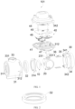
- the present invention provides a ball valve 101 which is applied in a gas meter.
- the ball valve 101 includes a valve body structure 30 and a driving structure 40.
- the valve body structure 30 includes a valve body 31 and a sealing component 100 of a valve.
- the valve body 31 is provided with a valve port 311.
- the sealing component 100 of the valve is installed in the valve body 31 and capable of opening or sealing the valve port 311.
- At least a part of the driving structure 40 is capable of extending into the valve body 31 and is connected to the sealing component 100 of the valve to drive the sealing component 100 of the valve to move in the valve body 31.
- the valve body structure 30 further includes a sealing member 32, which is surrounding the valve port 311 and configured to cooperate with the sealing component 100 of the valve to seal the valve port 311.
- a longitudinal cross section of the sealing member 32 is in a shape of any one of a convex polygon, an ellipse, a circle, a D-shape, or a waist shape, which is convenient for a time-saving and simple installation of the sealing member 32.
- a simple structure of the sealing member 32 it is convenient to process and manufacture the sealing member 32 at a low cost. Meanwhile, a normal pressing contact between the sealing component 100 of the valve and the sealing member 32 may be maintained, thus a good sealing effect may be achieved.
- a convex polygon refers to that if any one of sides of a polygon is infinitely extended to both sides into a straight line, and all the other sides are on the same side of the straight line, then the polygon is called a convex polygon.
- a first embodiment is provided. Referring to FIG. 3 , a shape of a longitudinal cross section of the sealing member 32 in the first embodiment is circular.
- a second embodiment is provided. Referring to FIG. 4 , the shape of the longitudinal cross section of the sealing member 32 in the second embodiment is elliptical.
- a third embodiment is provided. Referring to FIG. 5 , the shape of the longitudinal cross section of the sealing member 32 in the third embodiment is D-shaped.
- a fourth embodiment is provided. Referring to FIG. 6 , the shape of the longitudinal cross section of the sealing member 32 in the fourth embodiment is waist shaped.
- a fifth embodiment is provided. Referring to FIG. 7 , the shape of the longitudinal cross section of the sealing member 32 in the fifth embodiment is square.
- a sixth embodiment is provided. Referring to FIG. 8 , the shape of the longitudinal cross section of the sealing member 32 in the sixth embodiment is rectangular.
- a seventh embodiment is provided. Referring to FIG. 9 , the shape of the longitudinal cross section of the sealing member 32 in the seventh embodiment is quadrilateral.
- An eighth embodiment is provided. Referring to FIG. 10 , the shape of the longitudinal cross section of the sealing member 32 in the eighth embodiment is hexagonal.
- a ninth embodiment is provided. Referring to FIG. 11 , the shape of the longitudinal cross section of the sealing member 32 in the ninth embodiment is a regular hexagon.
- a tenth embodiment is provided. Referring to FIG. 12 , the shape of the longitudinal cross section of the sealing member 32 in the tenth embodiment is a regular octagon.
- the shape of the longitudinal cross section of the sealing member 32 in FIG. 7 to FIG. 12 is a convex polygon.
- the convex polygon, the ellipse, the circle, the D-shape and the waist shape are not limited to those shown in the drawings.
- dimensions or shapes of the convex polygon, the ellipse, the circle, the D-shape and the waist shape may be changed as required as long as definitions of the convex polygon, the ellipse, the circle, the D-shape and the waist shape are satisfied.
- a sealing groove 313 is provided at an end close to the valve port 311 of the valve body 31, and at least a part of the sealing member 32 is installed in the sealing groove 313.
- the valve body structure 30 further includes a resisting member 314 which is installed in the valve body 31. An end of the resisting member 314 is capable of abutting against the sealing member 32 to limit the sealing member 32. In this way, it is convenient to install and fix the sealing member 32, so that the sealing member 32 is not easy to detach.
- a shape of the sealing member 32 is an annular cylinder, i.e., the shape of the longitudinal cross section of the sealing member 32 is rectangular or square.
- the sealing member 32 in an annular cylinder has a simple structure, so that it is convenient to process and manufacture the sealing member 32 at a low cost by a simple process. Meanwhile, when installing the sealing member 32, there is no need to distinguish a front side and a back side, which may lead to a convenient, quick, and simple installation and a good sealing performance.
- the valve body structure 30 further includes a valve bonnet 34 and an elastic member 35.
- the valve bonnet 34 is installed on an end away from the valve port 311 of the valve body 31, and at least a part of the valve bonnet 34 is capable of extending into the valve body 31 and abuts against the sealing component 100 of the valve.
- the elastic member 35 is located between the valve bonnet 34 and the sealing component 100 of the valve. A first end of the elastic member 35 abuts against the valve bonnet 34, and a second end of the elastic member 35 abuts against the sealing component 100 of the valve. In this way, an arrangement of the elastic member 35 may provide a support for the sealing component 100 of the valve. Thus, a movement of the sealing component 100 of the valve may be facilitated, and a smoothness of the movement of the sealing component 100 of the valve may be improved.
- the elastic member 35 includes a planar spring 36. Due to a simple structure of the planar spring 36, it is convenient to install and disassemble the planar spring 36, and during an installation, a relatively large installation deviation may be allowed. In addition, the planar spring 36 may better cooperate with the sealing component 100 of the valve to provide a support. Moreover, the planar spring 36 may have a long service life, a good cushioning effect and a strong bearing capacity.
- the elastic member 35 includes a deformation segment 351 and a mounting segment 352.
- the deformation segment 351 includes at least one deformation unit 3511.
- the deformation element 3511 is U-shaped, and at least one deformation unit 3511 is sequentially connected to define a substantially corrugated deformation segment 351.
- the mounting segment 352 is located at an end of the deformation segment 351, connected to the deformation segment 351, and located in the same horizontal plane as the deformation segment 351.
- the sealing component 100 of the valve abuts against the mounting segment 352, so that the mounting segment 352 may better cooperate with the sealing component 100 of the valve, thus facilitating an assembly.
- the sealing component 100 of the valve includes a mounting portion 231.
- the mounting segment 352 includes a recessed unit 3521 that is depressed along a direction away from the sealing component 100 of the valve, and a peripheral side of the mounting portion 231 abuts against the recessed unit 3521.
- a shape of the recessed unit 3521 is matched with a shape of the peripheral side of the mounting portion 231.
- the mounting portion 231 is capable of abutting against the recessed unit 3521, so that a fast and stable installation may be realized.
- a misalignment may not occur, thereby improving a stability of an overall structure of the sealing component 100 of the valve and increasing a rapidity of the installation.
- a mounting groove 341 is located on the valve bonnet 34.
- a fitting groove 2311 is located on an outer side wall of the mounting portion 231.
- At least a part of the elastic member 35 is installed in the mounting groove 341.
- a first end of the elastic member 35 abuts against the valve bonnet 34, and a second end of the elastic member 35 is installed in the fitting groove 2311.
- the elastic member 35 can better cooperate with the fitting groove 2311 to provide a better support for the sealing component 100 of the valve, such that the sealing component 100 of the valve can move stably.
- the valve body 31 is connected to the valve bonnet 34 by means of an ultrasonic welding or a hot melt connection.
- an ultrasonic welding high-frequency vibration waves are transmitted to surfaces of the valve body 31 and the valve bonnet 34, and under pressure, the surfaces of the valve body 31 and the valve bonnet 34 may rub against each other to define a fusion between molecular layers.
- the ultrasonic welding may have characteristics of a fast welding speed, a short welding time, a high welding strength, and a good sealing performance.
- the ultrasonic welding may be cost effective, clean and pollution-free.
- the hot melt connection may have advantages such as a simple connection, a long service life, and an ability of resisting corrosion.
- the valve bonnet 34 is provided with a cylindrical convex block 342, and the valve body 31 is provided with a through hole 312.
- the cylindrical convex block 342 is capable of extending through the through hole 312.
- An end of the convex block 342 may be deformed into a mushroom head shape by an ultrasonic welding or a hot melt connection, so that the valve bonnet 34 and the valve body 31 may be fixed and connected to each other.
- the driving structure 40 includes a base 41 and an upper cover 44.
- the upper cover 44 is disposed on the base 41 and connected to the base 41 by means of an ultrasonic welding or a hot melt connection.
- the ultrasonic welding may have a fast welding speed, a short welding time, a high welding strength, and a good sealing performance.
- the ultrasonic welding may be cost effective, clean and pollution-free.
- the hot melt connection has advantages such as a simple connection, a long service life, and an ability of resisting corrosion.
- a connection between the base 41 and the upper cover 44 is in a same manner as that between the valve bonnet 34 and the valve body 31, that is, the base 41 is also provided with a through hole 312, and the upper cover 44 is also provided with a convex block 342. Descriptions of specific connection methods will not be given herein.
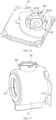
- an outer side wall of the valve body 31 is provided with a connecting portion 33, and a side close to the valve body 31 of the base 41 is provided with a fitting portion 42.
- the connecting portion 33 and the fitting portion 42 are coupled to and connected with each other. In this way, a quick connection between the valve body 31 and the base 41 may be realized.
- a part of the connecting portion 33 protruding in a circumferential direction is defined as a connecting block 331.
- the fitting portion 42 includes a connecting groove structure 421.
- the connecting block 331 is capable of extending into the connecting groove structure 421 and being engaged with the connecting groove structure 421.
- the valve body 31 and the base 41 may be quickly engaged to each other by an arrangement of the connecting block 331 and the connecting groove structure 421.
- a simple structure may be implemented. Accordingly, a convenient and quick installation may be achieved.
- the connecting groove structure 421 includes a receiving groove 4211, a connecting groove 4212, and a resisting block 4213.
- the connecting block 331 is capable of extending into the receiving groove 4211.
- a side of the connecting groove 4212 is in communication with the receiving groove 4211.
- the resisting block 4213 is located at a side away from the receiving groove 4211 of the connecting groove 4212 and connected to a bottom of the connecting groove 4212.
- the connecting block 331 is capable of moving from the receiving groove 4211 to the connecting groove 4212 and abutting against the resisting block 4213.
- the connecting groove 4212 is capable of limiting a movement of the connecting block 331 along a height direction of the resisting block 4213. In this way, a simple structure of the connecting groove structure 421 and a quick installation may be realized, and thus it is convenient to limit the connecting block 331. Therefore, a quick installation between the valve body 31 and the base 41 may be realized.
- the number of the connecting block 331 is four.
- Four connecting blocks 331 are evenly separated from each other in a circumference of the connecting portion 33, and the four connecting blocks 331 are located in the same horizontal plane.
- the number of the connecting groove structure 421 is four.
- Four connecting groove structures 421 are connected with each other in order, and in two adjacent connecting groove structures 421, a resisting block 4213 of one of the two adjacent connecting groove structures 421 is connected to a receiving groove 4211 of the other of the two adjacent connecting groove structures 421. In this way, a connection between the valve body 31 and the base 41 may be firmer, thereby enhancing a connection stability of the overall structure.
- the number of the connecting block 331 and the number of the connecting groove structure 421 may be other numbers rather than four as long as the same or similar effects can be achieved.
- both the number of the connecting block 331 and the number of the connecting groove structure 421 may be five, six, or eight.
- the driving structure 40 has a mounting chamber 43.
- the driving structure 40 further includes an electric motor 45, a driving component 46, and a valve rod component 47.
- the electric motor 45 is mounted in the mounting chamber 43.
- the driving component 46 is installed in the mounting chamber 43 and connected to the electric motor 45.
- a first end of the valve rod component 47 is installed in the mounting chamber 43 and fitted with the driving component 46.
- a second end of the valve rod component 47 extends out of the mounting chamber 43 and further extends into the valve body 31 to be fitted with the mounting portion 231.
- the electric motor 45 is capable of driving the driving component 46 to move, and the driving component 46 is capable of driving the valve rod component 47 to rotate, thus enabling the valve rod component 47 to drive the sealing component 100 of the valve to rotate along an axis of the mounting portion 231, so as to open or seal the valve port 311.
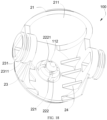
- the sealing component 100 of the valve of the present invention includes a rotating body 20 and a sealing structure 10.
- the rotating body 20 includes a flow-through surface 21 and a sealing surface 22 which are adjacent.
- an angle (not shown in the drawings) is defined between the flow-through surface 21 and the sealing surface 22.
- a flow-guiding hole 211 is located in the flow-through surface 21 for a medium to flow through.
- the sealing structure 10 is installed on the sealing surface 22 and capable of sealing the valve port 311 with a rotation of the rotating body 20.
- a material of the sealing structure 10 is a metal material. Since the sealing structure 10 is made of metal, the sealing structure 10 may have a high abrasion resistance, which may avoid wear of the sealing structure 10 due to repeated sealing of the valve port 311 by the driving of the rotating body 20, thereby prolonging a service life of the sealing component 100 of the valve. In addition, since the sealing structure 10 is made of metal, the sealing structure 10 is easy to be processed and manufactured. In addition, the sealing structure 10 made of metal is less likely to be deformed during processing, thus can be easily controlled in size and roundness. Therefore, a sealing performance of the sealing component 100 of the valve may be improved.
- the material of the sealing structure 10 is a plastic material, and thus a cost is low.
- an angle (not shown in the drawings) is defined between the flow-through surface 21 and the sealing surface 22, and the angle may be 90 degrees.
- the valve body 31 When the valve body 31 is in an open state, a medium can flow out of the flow-guiding hole 211. At this time, the sealing component 100 of the valve is rotated at 90 degrees, the sealing structure 10 may seal the valve port 311, thereby blocking the flow of the medium.
- the angle defined between the flow-through surface 21 and the sealing surface 22 may be set as required as long as the same function of opening or sealing the valve port 311 by rotation can be achieved.
- the angle defined between the flow-through surface 21 and the sealing surface 22 may be at 85 degrees, 70 degrees, or 60 degrees.
- sealing structure 10 is detachably installed on the sealing surface 22.
- the sealing structure 10 and the rotating body 20 are arranged separately, so as to facilitate the processing and manufacture of the sealing structure 10. Moreover, it is convenient to replace the sealing structure 10 when necessary.
- a material of the sealing structure 10 is stainless steel and is formed by computer numerical controlled (CNC) machining.
- the rotating body 20 is injection molded with a plastic material. If the sealing component 100 of the valve is all made of metal, the cost may be too high. By the sealing component 100 of the valve provided in the present invention, a sealing performance can be ensured, and a cost can be decreased.
- the sealing structure 10 includes a connecting column 11 and a sealing plate 12.
- the sealing plate 12 is configured for sealing the valve port 311, so as to block a flow of a medium.
- the connecting column 11 is disposed on a side surface of the sealing plate 12. A part of the sealing surface 22 depressing is defined as a fitting hole 221, and the connecting column 11 is capable of inserting into the fitting hole 221, enabling the sealing structure 10 to be installed on the sealing surface 22. Therefore, a connection between the sealing structure 10 and the rotating body 20 can be realized. Accordingly, it is convenient for the sealing structure 10 to seal the valve port 311 with a rotation of the rotating body 20.
- an inner side of the sealing surface 22 is provided with a buckling portion 222 surrounding a circumference of the fitting hole 221 and protruding along an axis of the fitting hole 221.
- a clamping slot 111 is located on the connecting column 11. After the connecting column 11 inserts into the fitting hole 221, the buckling portion 222 is capable of clamping into the clamping slot 111 as the connecting column 11 is gradually extended, thereby preventing the connecting column 11 from detaching from the fitting hole 221. Accordingly, a stability of connection between the sealing structure 10 and the rotating body 20 can be enhanced.
- the inner side of the sealing surface 22 is provided with a plurality of buckling portions 222, and the plurality of buckling portions 222 are separated from each other in a circumference of the fitting hole 221, so that the plurality of buckling portions 222 can further enhance a stable connection between the sealing structure 10 and the rotating body 20.
- the number of the buckle portions 222 is four.
- the number of the buckle portion 222 may be changed as required as long as the stable connection between the sealing structure 10 and the rotating body 20 can be further enhanced.
- the number of the buckle portion 222 may be three, five, or six.
- an end away from the sealing surface 22 of the buckling portion 222 is provided with a convex portion 2221 along a radial direction of the fitting hole 221.
- the connecting column 11 may press the convex portion 2221, such that the buckling portion 222 is deformed. Therefore, the convex portion 2221 may be forced to clamp into the clamping slot 111 during the connecting column 11 gradually inserting into the fitting hole 221, thus forming a buckle structure. Accordingly, a connection strength between the buckling portion 222 and the connecting column 11 may be enhanced, preventing the connecting column 11 from easily detaching from the fitting hole 221.
- the convex portion 2221 has a guiding surface 2222.
- the connecting column 11 is capable of pressing the buckle portion 222 under a guiding of the guiding surface 2222, enabling the buckle portion 222 to be deformed. Due to a guidance of the guiding surface 2222 to the connecting column 11, it is convenient for the connecting column 11 to insert into the fitting hole 221 and press the buckling portion 222, thus forcing the buckling portion 222 to be deformed.
- the connecting column 11 continues to extend in until the convex portion 2221 is clamped into the clamping slot 111. Therefore, a connection between the sealing structure 10 and the rotating body 20 may be realized.
- an end away from the sealing plate 12 of the connecting column 11 is provided with a guiding portion 112.
- the guiding portion 112 is configured to guide the connecting column 11 to insert into the fitting hole 221. Because of the guidance of the guiding portion 112, the connecting column 11 is capable of entering the fitting hole 221 more smoothly, such that the buckling portion 222 may be couple to the clamping slot 111.
- the guiding portion 112 firstly cooperates with the guiding surface 2222, and then presses the buckling portion 222 while continuing to insert into the fitting hole 221 by the guidance of the guiding surface 2222.
- the guiding portion 112 further extends into the fitting hole 221 and presses the buckling portion 222 by the guidance of the guiding portion 112, forcing the buckling portion 222 to spread out and be deformed until the convex portion 2221 is clamped into the clamping slot 111. Therefore, the connecting column 11 and the fitting hole 221 may be more quickly and easily connected by a simple structure, which greatly reduces a difficulty of installation.
- the guiding portion 112 is in a shape of a circular truncated cone.
- An inner diameter of an end away from the sealing surface 22 of the guiding portion 112 is less than an inner diameter of an end close to the sealing surface 22 of the guiding portion 112. Since the guiding portion 112 is in the shape of a circular truncated cone, the guidance of the guiding portion 112 may be enhanced and an installation thereof may be facilitated.
- a press strength of a circumferential side of the guiding portion 112 on the buckling portion 222 gradually increases, thus the buckling portion 222 is deformed.
- the convex portion 2221 is clamped into the clamping slot 111, thereby realizing a connection between the sealing structure 10 and the rotating body 20.
- the guiding portion 112 may be in other different shapes as long as the guiding portion 112 can play the same guiding function.
- the guiding portion 112 may be in a semi-elliptical shape.
- the rotating body 20 further includes two mounting surfaces 23.
- the mounting surface 23 and the flow-through surface 21 are perpendicular to each other, the flow-through surface 21 and the sealing surface 22 are perpendicular to each other, and the mounting surface 23 and the sealing surface 22 are perpendicular to each other.
- Two mounting portions 231 are provided on the two mounting surfaces 23, respectively.
- the mounting portion 231 is configured for connecting the valve rod component 47 which is capable of inserting into the mounting portion 231.
- a rotation of the valve rod component 47 may drive the sealing component 100 of the valve to rotate, thus sealing or opening the valve port 311.
- the rotating body 20 is further provided with a plurality of reinforcement bars 24.
- the plurality of reinforcement bars 24 are symmetrically distributed on a side close to an axis of the flow-through surface 21 of each mounting surface 23, and connected to sides away from the sealing plate 12 of the mounting surface 23 and the sealing surface 22, respectively, so as to strengthen an overall structural strength of the rotating body 20.
Landscapes
- Engineering & Computer Science (AREA)
- General Engineering & Computer Science (AREA)
- Mechanical Engineering (AREA)
- Taps Or Cocks (AREA)
- Valve Housings (AREA)
Claims (12)
- Kugelventil (101), umfassend eine Ventilkörperstruktur (30) und eine Antriebsstruktur (40), wobei die Ventilkörperstruktur (30) einen Ventilkörper (31) und eine Verschlusskomponente (100) eines Ventils umfasst, wobei der Ventilkörper (31) mit einer Ventilöffnung (311) versehen ist, die Verschlusskomponente (100) des Ventils im Ventilkörper (31) installiert und fähig ist, die Ventilöffnung (311) zu öffnen und zu verschließen, und wenigstens ein Teil der Antriebsstruktur (40) fähig ist, sich in den Ventilkörper (31) zu erstrecken und mit der Verschlusskomponente (100) des Ventils verbunden zu sein, um die Verschlusskomponente (100) des Ventils im Ventilkörper (31) zu bewegen,wobei die Ventilkörperstruktur (30) ferner eine Verschlusselement (32) umfasst, die die Ventilöffnung (311) umgibt und dazu ausgestaltet ist, mit der Verschlusskomponente (100) des Ventils zusammenzuwirken, um die Ventilöffnung (311) zu verschließen, wobei ein Längsschnitt des Verschlusselements (32) eine beliebige Form von einem konvexen Vieleck, einer Ellipse, einem Kreis, einer D-Form oder einer Sanduhrform aufweist;wobei die Verschlusskomponente (100) des Ventils einen Drehkörper (20) und eine Verschlussstruktur (10) aus einem Metallmaterial umfasst,wobei der Drehkörper (20) eine Durchflussfläche (21) und eine Verschlussfläche (22) umfasst, die zueinander benachbart sind, wobei zwischen der Durchflussfläche (21) und der Verschlussfläche (22) ein Winkel definiert ist und ein Flusslenkungsloch (211) in der Durchflussfläche (21) angeordnet ist, durch das ein Medium hindurchfließen kann, undwobei die Verschlussstruktur (10) an der Verschlussfläche (22) installiert ist und fähig ist, die Ventilöffnung (311) mit einer Drehung des Drehkörpers (20) zu verschließen;dadurch gekennzeichnet, dassdie Verschlussstruktur (10) umfasst:eine Verschlussplatte (12), die dazu ausgestaltet ist, die Ventilöffnung (311) zu verschließen; undeine Verbindungssäule (11), die an einer Seitenfläche der Verschlussplatte (12) angeordnet ist,wobei ein vertiefter Teil der Verschlussfläche (22) als ein Passloch (221) definiert ist und die Verbindungssäule (11) in das Passloch (221) einführbar ist, sodass die Verschlussstruktur (10) an der Verschlussfläche (22) installiert werden kann;wobei eine Innenseite der Verschlussfläche (22) mit einem Wölbungsabschnitt (222) versehen ist, der einen Umfang des Passloch (221) umgibt und an einer Achse des Passlochs (221) vorspringt, und ein Klemmschlitz (111) an der Verbindungssäule (11) angeordnet ist;wobei der Wölbungsabschnitt (222) nach dem Einführen der Verbindungssäule (11) in das Passloch (221) in den Klemmschlitz (111) geklemmt werden kann; undwobei die Innenseite der Verschlussfläche (22) mit einer Vielzahl von Wölbungsabschnitten (222) versehen ist und die Vielzahl von Wölbungsabschnitten (222) am Umfang des Passlochs (221) voneinander beabstandet ist.
- Kugelventil (101) nach Anspruch 1, dadurch gekennzeichnet, dass die Ventilkörperstruktur (30) ferner einen Ventilaufsatz (34) und ein elastisches Element (35) umfasst, wobeider Ventilaufsatz (34) an einem von der Ventilöffnung (311) des Ventilkörpers (31) entfernten Ende installiert ist und wenigstens ein Teil des Ventilaufsatzes (34) fähig ist, sich in den Ventilkörper (31) zu erstrecken, und an der Verschlusskomponente (100) des Ventils anliegt; unddas elastische Element (35) zwischen dem Ventilaufsatz (34) und der Verschlusskomponente (100) des Ventils angeordnet ist, wobei ein erstes Ende des elastischen Elements (35) am Ventilaufsatz (34) anliegt und ein zweites Ende des elastischen Elements (35) an der Verschlusskomponente (100) des Ventils anliegt.
- Kugelventil (101) nach Anspruch 2, dadurch gekennzeichnet, dass das elastische Element (35) eine flache Feder (36) umfasst.
- Kugelventil (101) nach Anspruch 2, dadurch gekennzeichnet, dass das elastische Element (35) umfasst:ein Verformungssegment (351), das wenigstens eine Verformungseinheit (3511) umfasst;ein Anbringungssegment (352), das an einem Ende von wenigstens einem Verformungssegment (351) angeordnet ist, mit dem wenigstens einen Verformungssegment (351) verbunden ist und in derselben horizontalen Ebene wie das wenigstens eine Verformungssegment (351) liegt,wobei die Verschlusskomponente (100) des Ventils an dem Anbringungssegment (352) anliegt;wobei die Verschlusskomponente (100) des Ventils einen Anbringungsabschnitt (231) umfasst und das Anbringungssegment (352) des elastischen Elements (35) eine Ausnehmungseinheit (3521) umfasst,wobei die Ausnehmungseinheit (3521) in einer Richtung weg von der Verschlusskomponente (100) des Ventils vertieft ist, eine Umfangsseite des Anbringungsabschnitts (231) an der Ausnehmungseinheit (3521) anliegt und eine Form der Ausnehmungseinheit (3521) mit einer Form der Umfangsseite des Anbringungsabschnitts (231) übereinstimmt; undeine Anbringungsnut (341) am Ventilaufsatz (34) angeordnet ist, eine Passnut (2311) an einer Außenseitenwand des Anbringungsabschnitts (231) angeordnet ist, wenigstens ein Teil des elastischen Elements (35) in der Anbringungsnut (341) installiert ist, ein erstes Ende des elastischen Elements (35) am Ventilaufsatz (34) anliegt und ein zweites Ende des elastischen Elements (35) in der Passnut (2311) installiert ist.
- Kugelventil (101) nach Anspruch 2, dadurch gekennzeichnet, dass der Ventilkörper (31) mittels einer Ultraschallschweiß- oder Schmelzverbindung mit dem Ventilaufsatz (34) verbunden ist.
- Kugelventil (101) nach Anspruch 1, dadurch gekennzeichnet, dass die Antriebsstruktur (40) einen Sockel (41) und eine obere Abdeckung (44) umfasst, wobei die obere Abdeckung (44) auf dem Sockel (41) angeordnet und mittels einer Ultraschallschweiß- oder Schmelzverbindung mit dem Sockel (41) verbunden ist;wobei eine Außenseitenwand des Ventilskörper (31) mit einem Verbindungsabschnitt (33) versehen ist, eine Seite des Sockels (41) nah am Ventilkörper (31) mit einem Passabschnitt (42) versehen ist und der Verbindungsabschnitt (33) und der Passabschnitt (42) aneinander gekoppelt und miteinander verbunden sind;wobei ein Teil des Verbindungsabschnitts (33), der in Umfangsrichtung vorspringt, als ein Verbindungsblock (331) definiert ist, der Passabschnitt (42) eine Verbindungsnutstruktur (421) umfasst und der Verbindungsblock (331) fähig ist, sich in die Verbindungsnutstruktur (421) zu erstrecken und mit der Verbindungsnutstruktur (421) in Eingriff zu treten;wobei die Verbindungsnutstruktur (421) umfasst:eine Aufnahmenut (4211), wobei der Verbindungsblock (331) fähig ist, sich in die Aufnahmenut (4211) zu erstrecken;eine Verbindungsnut (4212), deren eine Seite mit der Aufnahmenut (4211) in Verbindung steht; undeinen Widerstandsblock (4213), der an einer von der Aufnahmenut (4211) entfernten Seite der Verbindungsnut (4212) angeordnet und mit einem Boden der Verbindungsnut (4212) verbunden ist,wobei der Verbindungsblock (331) fähig ist, sich von der Aufnahmenut (4211) zur Verbindungsnut (4212) zu bewegen und in Anlage an den Widerstandsblock (4213) zu gelangen, und die Verbindungsnut (4212) fähig ist, eine Bewegung des Verbindungsblocks (331) in einer Höhenrichtung des Widerstandsblocks (4213) zu begrenzen;wobei der Verbindungsblock (331) in einer Anzahl von vier vorliegt, die vier Verbindungsblöcke (331) an einem Umfang des Verbindungsabschnitts (33) gleichmäßig voneinander beabstandet sind und die vier Verbindungsblöcke (331) in derselben horizontalen Ebene liegen; undwobei die Verbindungsnutstruktur (421) in einer Anzahl von vier vorliegt, die vier Verbindungsnutstrukturen (421) der Reihe nach miteinander verbunden sind und in zwei benachbarten Verbindungsnutstrukturen (421) ein Widerstandsblock (4213) von einer der zwei benachbarten Verbindungsnutstrukturen (421) mit der Aufnahmenut (4211) der anderen der zwei benachbarten Verbindungsnutstrukturen (421) verbunden ist.
- Kugelventil (101) nach Anspruch 4, dadurch gekennzeichnet, dass die Antriebsstruktur (40) eine Anbringungskammer (43) aufweist und die Antriebsstruktur (40) ferner umfasst:einen Elektromotor (45), der in der Anbringungskammer (43) installiert ist;eine Antriebskomponente (46), die in der Anbringungskammer (43) installiert und mit dem Elektromotor (45) verbunden ist; undeine Ventilschaftkomponente (47), deren erstes Ende in der Anbringungskammer (43) installiert und mit der Antriebskomponente (46) zusammengesetzt ist; und deren zweites Ende sich aus der Anbringungskammer (43) heraus und weiter in den Ventilkörper (31) hinein erstreckt, um mit dem Anbringungsabschnitt (231) zusammengesetzt zu sein,wobei der Elektromotor (45) fähig ist, die Antriebskomponente (46) zur Bewegung anzutreiben, und die Antriebskomponente (46) fähig ist, die Ventilschaftkomponente (47) drehend anzutreiben, wodurch die Ventilschaftkomponente (47) die Verschlusskomponente (100) des Ventils so antreiben kann, dass sie sich an einer Achse des Anbringungsabschnitt (231) dreht, um die Ventilöffnung (311) zu öffnen oder zu verschließen.
- Kugelventil (101) nach Anspruch 1, dadurch gekennzeichnet, dass ein von der Verschlussfläche (22) entferntes Ende des Wölbungsabschnitts (222) mit einem konvexen Abschnitt (2221) versehen ist, der in einer radialen Richtung des Passlochs (221) vorspringt, und der konvexe Abschnitt (2221) fähig ist, nach dem Einführen der Verbindungssäule (11) in das Passloch (221) in den Klemmschlitz (111) geklemmt zu werden; und
wobei der konvexe Abschnitt (2221) eine Führungsfläche (2222) aufweist und die Verbindungssäule (11) während des Einführens der Verbindungssäule (11) in das Passloch (221) fähig ist, den Wölbungsabschnitt (222) unter Führung durch die Führungsfläche (2222) zu drücken, sodass der Wölbungsabschnitt (222) verformt werden kann. - Kugelventil (101) nach Anspruch 1, dadurch gekennzeichnet, dass ein von der Verschlussplatte (12) entferntes Ende der Verbindungssäule (11) mit einem Führungsabschnitt (112) versehen ist und der Führungsabschnitt (112) dazu ausgestaltet ist, die Verbindungssäule (11) beim Einführen in das Passloch (221) zu führen; und
wobei der Führungsabschnitt (112) die Form eines kreisförmigen Kegelstumpfs aufweist und ein Innendurchmesser eines von der Verschlussfläche (22) entfernten Endes des Führungsabschnitts (112) kleiner als ein Innendurchmesser eines nah an der Verschlussfläche (22) liegenden Endes des Führungsabschnitts (112) ist. - Verschlusskomponente (100) für ein Ventil, die geeignet ist, um in einem Ventilkörper (31) installiert zu sein, wobei der Ventilkörper (31) eine Ventilöffnung (311) aufweist, die Verschlusskomponente (100) des Ventils eine Drehkörper (20) und eine Verschlussstruktur (10) aus einem Metallmaterial umfasst, der Drehkörper (20) mit einer Durchflussfläche (21) und einer Verschlussfläche (22) versehen ist, die zueinander benachbart sind, zwischen der Durchflussfläche (21) und der Verschlussfläche (22) ein Winkel definiert ist, die Durchflussfläche (21) mit einem Flusslenkungsloch (211) versehen ist, durch das ein Medium hindurchfließen kann, und die Verschlussstruktur (10) aus Metallmaterial an der Verschlussfläche (22) installiert ist und fähig ist, die Ventilöffnung (311) mit einer Drehung des Drehkörpers (20) zu verschließen;
dadurch gekennzeichnet, dass
die Verschlussstruktur (10) aus Metallmaterial umfasst:eine Verschlussplatte (12), die dazu ausgestaltet ist, den Ventilkörper (31) zu verschließen; undeine Verbindungssäule (11), die an einer Seitenfläche der Verschlussplatte (12) angeordnet ist,wobei ein vertiefter Teil der Verschlussfläche (22) als ein Passloch (221) definiert ist und die Verbindungssäule (11) in das Passloch (221) einführbar ist, sodass die Verschlussstruktur (10) aus Metallmaterial an der Verschlussfläche (22) installiert werden kann;wobei eine Innenseite der Verschlussfläche (22) mit einem Wölbungsabschnitt (222) versehen ist, der einen Umfang des Passloch (221) umgibt und an einer Achse des Passlochs (221) vorspringt, und ein Klemmschlitz (111) an der Verbindungssäule (11) angeordnet ist;wobei der Wölbungsabschnitt (222) nach dem Einführen der Verbindungssäule (11) in das Passloch (221) in den Klemmschlitz (111) geklemmt werden kann; undwobei die Innenseite der Verschlussfläche (22) mit einer Vielzahl von Wölbungsabschnitten (222) versehen ist und die Vielzahl von Wölbungsabschnitten (222) am Umfang des Passlochs (221) voneinander beabstandet ist. - Verschlusskomponente (100) für ein Ventil nach Anspruch 10, dadurch gekennzeichnet, dass ein von der Verschlussfläche (22) entferntes Ende des Wölbungsabschnitts (222) mit einem konvexen Abschnitt (2221) versehen ist, der in einer radialen Richtung des Passlochs (221) vorspringt, und der konvexe Abschnitt (2221) fähig ist, nach dem Einführen der Verbindungssäule (11) in das Passloch (221) in den Klemmschlitz (111) geklemmt zu werden; und
wobei der konvexe Abschnitt (2221) eine Führungsfläche (2222) aufweist und die Verbindungssäule (11) während des Einführens der Verbindungssäule (11) in das Passloch (221) fähig ist, den Wölbungsabschnitt (222) unter Führung durch die Führungsfläche (2222) zu drücken, sodass der Wölbungsabschnitt (222) verformt werden kann. - Verschlusskomponente (100) für ein Ventil nach Anspruch 10, dadurch gekennzeichnet, dass ein von der Verschlussplatte (12) entferntes Ende der Verbindungssäule (11) mit einem Führungsabschnitt (112) versehen ist und der Führungsabschnitt (112) dazu ausgestaltet ist, die Verbindungssäule (11) beim Einführen in das Passloch (221) zu führen; und
wobei der Führungsabschnitt (112) die Form eines kreisförmigen Kegelstumpfs aufweist und ein Innendurchmesser eines von der Verschlussfläche (22) entfernten Endes des Führungsabschnitts (112) kleiner als ein Innendurchmesser eines nah an der Verschlussfläche (22) liegenden Endes des Führungsabschnitts (112) ist.
Applications Claiming Priority (2)
| Application Number | Priority Date | Filing Date | Title |
|---|---|---|---|
| CN202023044719.5U CN214146676U (zh) | 2020-12-16 | 2020-12-16 | 阀门密封组件及具有其的阀门 |
| PCT/CN2021/138334 WO2022127822A1 (zh) | 2020-12-16 | 2021-12-15 | 球阀 |
Publications (3)
| Publication Number | Publication Date |
|---|---|
| EP4080094A1 EP4080094A1 (de) | 2022-10-26 |
| EP4080094A4 EP4080094A4 (de) | 2023-08-30 |
| EP4080094B1 true EP4080094B1 (de) | 2024-10-16 |
Family
ID=77587792
Family Applications (1)
| Application Number | Title | Priority Date | Filing Date |
|---|---|---|---|
| EP21905749.4A Active EP4080094B1 (de) | 2020-12-16 | 2021-12-15 | Kugelventil |
Country Status (6)
| Country | Link |
|---|---|
| EP (1) | EP4080094B1 (de) |
| CN (2) | CN214146676U (de) |
| DK (1) | DK4080094T3 (de) |
| ES (1) | ES3010508T3 (de) |
| PL (1) | PL4080094T3 (de) |
| WO (1) | WO2022127822A1 (de) |
Families Citing this family (3)
| Publication number | Priority date | Publication date | Assignee | Title |
|---|---|---|---|---|
| CN214146676U (zh) * | 2020-12-16 | 2021-09-07 | 慈溪市三洋电子有限公司 | 阀门密封组件及具有其的阀门 |
| CN114960887B (zh) * | 2022-07-20 | 2025-09-26 | 佛山市恒洁卫浴有限公司 | 马桶的主冲管连接配件、主冲管组件和马桶 |
| CN117722510B (zh) * | 2024-02-06 | 2024-04-09 | 成都成高阀门股份有限公司 | 一种具有球面自清洁机构的球阀 |
Family Cites Families (15)
| Publication number | Priority date | Publication date | Assignee | Title |
|---|---|---|---|---|
| FR1530079A (fr) * | 1967-01-12 | 1968-06-21 | Fisher Governor Co | Robinet à rotule ou noix sphérique munie d'un chapeau d'étanchéité |
| DE1750300A1 (de) * | 1967-11-13 | 1971-02-11 | Torsten Ramen | Kugelsektorventil |
| DE7506291U (de) * | 1975-02-28 | 1976-09-23 | Honeywell Gmbh, 6000 Frankfurt | Entil mit einem eine kugelsegmentfoermige dichtflaeche aufweisenden drosselkoerper |
| EP0146568B1 (de) * | 1983-05-31 | 1990-11-28 | B.C. RICHARDS & CO. PTY. LTD. | Ventildichtung für kryogene verwendung |
| CN201582435U (zh) * | 2010-01-01 | 2010-09-15 | 浙江正华阀门厂 | 球阀 |
| CN202048234U (zh) * | 2011-05-16 | 2011-11-23 | 伯特利阀门集团有限公司 | 高温金属密封球阀 |
| DE102011110384B4 (de) * | 2011-08-17 | 2019-04-18 | Johnson Electric Dresden Gmbh | Elektromotorisch betriebenes Ventil |
| JP5871432B2 (ja) * | 2012-08-10 | 2016-03-01 | 日本サーモスタット株式会社 | ロータリ式バルブ用シール部材及びこれを用いたロータリ式バルブ |
| CN104595517B (zh) * | 2014-12-31 | 2017-02-08 | 上海鸿研物流技术有限公司 | 阀门及其阀芯组件 |
| KR101913115B1 (ko) * | 2017-03-06 | 2018-10-31 | 동주에이피 주식회사 | 돔 밸브 |
| KR102002870B1 (ko) * | 2017-10-27 | 2019-10-17 | (주)대한시브이디 | 나사식 용접식의 초고경도 적용한 부품의 돔 밸브 |
| KR101925092B1 (ko) * | 2017-11-28 | 2018-12-04 | 주식회사 대한시브이디 | 내마모성이 향상된 볼 및 이를 이용한 볼 밸브 |
| DE102018123724A1 (de) * | 2018-09-26 | 2020-03-26 | Johnson Electric Germany GmbH & Co. KG | Dichtungssystem für ein Ventil |
| CN110701337A (zh) * | 2019-11-07 | 2020-01-17 | 慈溪市凯迪电子有限公司 | 一种燃气表球阀的阀体与球体密封结构 |
| CN214146676U (zh) * | 2020-12-16 | 2021-09-07 | 慈溪市三洋电子有限公司 | 阀门密封组件及具有其的阀门 |
-
2020
- 2020-12-16 CN CN202023044719.5U patent/CN214146676U/zh active Active
-
2021
- 2021-12-15 DK DK21905749.4T patent/DK4080094T3/da active
- 2021-12-15 CN CN202190000319.8U patent/CN219062500U/zh active Active
- 2021-12-15 PL PL21905749.4T patent/PL4080094T3/pl unknown
- 2021-12-15 EP EP21905749.4A patent/EP4080094B1/de active Active
- 2021-12-15 ES ES21905749T patent/ES3010508T3/es active Active
- 2021-12-15 WO PCT/CN2021/138334 patent/WO2022127822A1/zh not_active Ceased
Also Published As
| Publication number | Publication date |
|---|---|
| PL4080094T3 (pl) | 2025-01-27 |
| EP4080094A1 (de) | 2022-10-26 |
| CN219062500U (zh) | 2023-05-23 |
| WO2022127822A1 (zh) | 2022-06-23 |
| CN214146676U (zh) | 2021-09-07 |
| EP4080094A4 (de) | 2023-08-30 |
| DK4080094T3 (da) | 2024-12-16 |
| ES3010508T3 (en) | 2025-04-03 |
Similar Documents
| Publication | Publication Date | Title |
|---|---|---|
| EP4080094A1 (de) | Kugelventil | |
| EP2140180B1 (de) | Kugelventil mit entfernbarem mittel zum festhalten der axialdichtung | |
| CN102261488B (zh) | 球阀座密封件 | |
| JP7543440B2 (ja) | 回転バルブ | |
| EP2118536B1 (de) | Röhrenendklappenmess- und sperrventil | |
| JPH0147671B2 (de) | ||
| EP3882498B1 (de) | Drosselventil | |
| KR20120129992A (ko) | 볼 밸브 | |
| EP3739245B1 (de) | Absperrklappe | |
| CN215487760U (zh) | 一种阀座、旋塞阀以及压裂管汇 | |
| KR101476518B1 (ko) | 버터플라이 밸브의 밸브체 | |
| EP1941188A2 (de) | Abdichtung zur anwendung mit rohr- und flanschbaugruppen | |
| EP0025402B1 (de) | Ventil für Tieftemperaturbetrieb und Dichtung dafür | |
| US7357372B2 (en) | Seat ring for butterfly valve | |
| SK286206B6 (sk) | Guľový ventil | |
| EP3341635B1 (de) | Ventil, ventilsitz und verfahren zur veränderung eines ventils | |
| KR102932922B1 (ko) | 버터플라이 밸브 | |
| EP2817546B1 (de) | Schräge kontaktoberflächen in einer ventilvorrichtung | |
| CN113565979A (zh) | 球阀密封件及球阀 | |
| CN212616443U (zh) | 球阀密封件及球阀 | |
| CN210240623U (zh) | 一种减少旋塞阀扭矩的旋塞结构 | |
| CN222011020U (zh) | 阀座密封组件和阀门 | |
| US20060186367A1 (en) | Butterfly valve | |
| CN220242257U (zh) | 聚氨酯垫圈注塑模具 | |
| KR200311759Y1 (ko) | 버터플라이 밸브 |
Legal Events
| Date | Code | Title | Description |
|---|---|---|---|
| STAA | Information on the status of an ep patent application or granted ep patent |
Free format text: STATUS: THE INTERNATIONAL PUBLICATION HAS BEEN MADE |
|
| PUAI | Public reference made under article 153(3) epc to a published international application that has entered the european phase |
Free format text: ORIGINAL CODE: 0009012 |
|
| STAA | Information on the status of an ep patent application or granted ep patent |
Free format text: STATUS: REQUEST FOR EXAMINATION WAS MADE |
|
| 17P | Request for examination filed |
Effective date: 20220719 |
|
| AK | Designated contracting states |
Kind code of ref document: A1 Designated state(s): AL AT BE BG CH CY CZ DE DK EE ES FI FR GB GR HR HU IE IS IT LI LT LU LV MC MK MT NL NO PL PT RO RS SE SI SK SM TR |
|
| A4 | Supplementary search report drawn up and despatched |
Effective date: 20230801 |
|
| RIC1 | Information provided on ipc code assigned before grant |
Ipc: F16K 27/10 20060101ALI20230726BHEP Ipc: F16K 5/20 20060101ALI20230726BHEP Ipc: F16K 5/08 20060101ALI20230726BHEP Ipc: F16K 5/06 20060101AFI20230726BHEP |
|
| DAV | Request for validation of the european patent (deleted) | ||
| DAX | Request for extension of the european patent (deleted) | ||
| GRAP | Despatch of communication of intention to grant a patent |
Free format text: ORIGINAL CODE: EPIDOSNIGR1 |
|
| STAA | Information on the status of an ep patent application or granted ep patent |
Free format text: STATUS: GRANT OF PATENT IS INTENDED |
|
| RIC1 | Information provided on ipc code assigned before grant |
Ipc: F16K 27/10 20060101ALI20240425BHEP Ipc: F16K 5/20 20060101ALI20240425BHEP Ipc: F16K 5/08 20060101ALI20240425BHEP Ipc: F16K 5/06 20060101AFI20240425BHEP |
|
| INTG | Intention to grant announced |
Effective date: 20240522 |
|
| GRAS | Grant fee paid |
Free format text: ORIGINAL CODE: EPIDOSNIGR3 |
|
| GRAA | (expected) grant |
Free format text: ORIGINAL CODE: 0009210 |
|
| STAA | Information on the status of an ep patent application or granted ep patent |
Free format text: STATUS: THE PATENT HAS BEEN GRANTED |
|
| AK | Designated contracting states |
Kind code of ref document: B1 Designated state(s): AL AT BE BG CH CY CZ DE DK EE ES FI FR GB GR HR HU IE IS IT LI LT LU LV MC MK MT NL NO PL PT RO RS SE SI SK SM TR |
|
| REG | Reference to a national code |
Ref country code: GB Ref legal event code: FG4D |
|
| REG | Reference to a national code |
Ref country code: CH Ref legal event code: EP |
|
| REG | Reference to a national code |
Ref country code: IE Ref legal event code: FG4D |
|
| REG | Reference to a national code |
Ref country code: DE Ref legal event code: R096 Ref document number: 602021020498 Country of ref document: DE |
|
| REG | Reference to a national code |
Ref country code: DK Ref legal event code: T3 Effective date: 20241209 |
|
| REG | Reference to a national code |
Ref country code: LT Ref legal event code: MG9D |
|
| REG | Reference to a national code |
Ref country code: AT Ref legal event code: MK05 Ref document number: 1733150 Country of ref document: AT Kind code of ref document: T Effective date: 20241016 |
|
| PG25 | Lapsed in a contracting state [announced via postgrant information from national office to epo] |
Ref country code: NL Free format text: LAPSE BECAUSE OF FAILURE TO SUBMIT A TRANSLATION OF THE DESCRIPTION OR TO PAY THE FEE WITHIN THE PRESCRIBED TIME-LIMIT Effective date: 20241016 |
|
| PG25 | Lapsed in a contracting state [announced via postgrant information from national office to epo] |
Ref country code: NL Free format text: LAPSE BECAUSE OF FAILURE TO SUBMIT A TRANSLATION OF THE DESCRIPTION OR TO PAY THE FEE WITHIN THE PRESCRIBED TIME-LIMIT Effective date: 20241016 |
|
| PG25 | Lapsed in a contracting state [announced via postgrant information from national office to epo] |
Ref country code: IS Free format text: LAPSE BECAUSE OF FAILURE TO SUBMIT A TRANSLATION OF THE DESCRIPTION OR TO PAY THE FEE WITHIN THE PRESCRIBED TIME-LIMIT Effective date: 20250216 Ref country code: HR Free format text: LAPSE BECAUSE OF FAILURE TO SUBMIT A TRANSLATION OF THE DESCRIPTION OR TO PAY THE FEE WITHIN THE PRESCRIBED TIME-LIMIT Effective date: 20241016 Ref country code: PT Free format text: LAPSE BECAUSE OF FAILURE TO SUBMIT A TRANSLATION OF THE DESCRIPTION OR TO PAY THE FEE WITHIN THE PRESCRIBED TIME-LIMIT Effective date: 20250217 |
|
| PG25 | Lapsed in a contracting state [announced via postgrant information from national office to epo] |
Ref country code: FI Free format text: LAPSE BECAUSE OF FAILURE TO SUBMIT A TRANSLATION OF THE DESCRIPTION OR TO PAY THE FEE WITHIN THE PRESCRIBED TIME-LIMIT Effective date: 20241016 |
|
| PG25 | Lapsed in a contracting state [announced via postgrant information from national office to epo] |
Ref country code: BG Free format text: LAPSE BECAUSE OF FAILURE TO SUBMIT A TRANSLATION OF THE DESCRIPTION OR TO PAY THE FEE WITHIN THE PRESCRIBED TIME-LIMIT Effective date: 20241016 |
|
| PG25 | Lapsed in a contracting state [announced via postgrant information from national office to epo] |
Ref country code: NO Free format text: LAPSE BECAUSE OF FAILURE TO SUBMIT A TRANSLATION OF THE DESCRIPTION OR TO PAY THE FEE WITHIN THE PRESCRIBED TIME-LIMIT Effective date: 20250116 |
|
| PG25 | Lapsed in a contracting state [announced via postgrant information from national office to epo] |
Ref country code: AT Free format text: LAPSE BECAUSE OF FAILURE TO SUBMIT A TRANSLATION OF THE DESCRIPTION OR TO PAY THE FEE WITHIN THE PRESCRIBED TIME-LIMIT Effective date: 20241016 Ref country code: LV Free format text: LAPSE BECAUSE OF FAILURE TO SUBMIT A TRANSLATION OF THE DESCRIPTION OR TO PAY THE FEE WITHIN THE PRESCRIBED TIME-LIMIT Effective date: 20241016 Ref country code: GR Free format text: LAPSE BECAUSE OF FAILURE TO SUBMIT A TRANSLATION OF THE DESCRIPTION OR TO PAY THE FEE WITHIN THE PRESCRIBED TIME-LIMIT Effective date: 20250117 |
|
| PG25 | Lapsed in a contracting state [announced via postgrant information from national office to epo] |
Ref country code: RS Free format text: LAPSE BECAUSE OF FAILURE TO SUBMIT A TRANSLATION OF THE DESCRIPTION OR TO PAY THE FEE WITHIN THE PRESCRIBED TIME-LIMIT Effective date: 20250116 |
|
| PG25 | Lapsed in a contracting state [announced via postgrant information from national office to epo] |
Ref country code: SM Free format text: LAPSE BECAUSE OF FAILURE TO SUBMIT A TRANSLATION OF THE DESCRIPTION OR TO PAY THE FEE WITHIN THE PRESCRIBED TIME-LIMIT Effective date: 20241016 |
|
| PG25 | Lapsed in a contracting state [announced via postgrant information from national office to epo] |
Ref country code: MC Free format text: LAPSE BECAUSE OF FAILURE TO SUBMIT A TRANSLATION OF THE DESCRIPTION OR TO PAY THE FEE WITHIN THE PRESCRIBED TIME-LIMIT Effective date: 20241016 |
|
| REG | Reference to a national code |
Ref country code: DE Ref legal event code: R097 Ref document number: 602021020498 Country of ref document: DE |
|
| PG25 | Lapsed in a contracting state [announced via postgrant information from national office to epo] |
Ref country code: EE Free format text: LAPSE BECAUSE OF FAILURE TO SUBMIT A TRANSLATION OF THE DESCRIPTION OR TO PAY THE FEE WITHIN THE PRESCRIBED TIME-LIMIT Effective date: 20241016 |
|
| PG25 | Lapsed in a contracting state [announced via postgrant information from national office to epo] |
Ref country code: SK Free format text: LAPSE BECAUSE OF FAILURE TO SUBMIT A TRANSLATION OF THE DESCRIPTION OR TO PAY THE FEE WITHIN THE PRESCRIBED TIME-LIMIT Effective date: 20241016 |
|
| REG | Reference to a national code |
Ref country code: CH Ref legal event code: PL |
|
| PG25 | Lapsed in a contracting state [announced via postgrant information from national office to epo] |
Ref country code: LU Free format text: LAPSE BECAUSE OF NON-PAYMENT OF DUE FEES Effective date: 20241215 |
|
| PLBE | No opposition filed within time limit |
Free format text: ORIGINAL CODE: 0009261 |
|
| STAA | Information on the status of an ep patent application or granted ep patent |
Free format text: STATUS: NO OPPOSITION FILED WITHIN TIME LIMIT |
|
| PG25 | Lapsed in a contracting state [announced via postgrant information from national office to epo] |
Ref country code: SE Free format text: LAPSE BECAUSE OF FAILURE TO SUBMIT A TRANSLATION OF THE DESCRIPTION OR TO PAY THE FEE WITHIN THE PRESCRIBED TIME-LIMIT Effective date: 20241016 |
|
| 26N | No opposition filed |
Effective date: 20250717 |
|
| PG25 | Lapsed in a contracting state [announced via postgrant information from national office to epo] |
Ref country code: CH Free format text: LAPSE BECAUSE OF NON-PAYMENT OF DUE FEES Effective date: 20241231 |
|
| PG25 | Lapsed in a contracting state [announced via postgrant information from national office to epo] |
Ref country code: IE Free format text: LAPSE BECAUSE OF NON-PAYMENT OF DUE FEES Effective date: 20241215 |
|
| PGFP | Annual fee paid to national office [announced via postgrant information from national office to epo] |
Ref country code: GB Payment date: 20251121 Year of fee payment: 5 |
|
| PGFP | Annual fee paid to national office [announced via postgrant information from national office to epo] |
Ref country code: IT Payment date: 20251210 Year of fee payment: 5 Ref country code: DK Payment date: 20251120 Year of fee payment: 5 |
|
| PGFP | Annual fee paid to national office [announced via postgrant information from national office to epo] |
Ref country code: FR Payment date: 20251120 Year of fee payment: 5 |
|
| PGFP | Annual fee paid to national office [announced via postgrant information from national office to epo] |
Ref country code: TR Payment date: 20251210 Year of fee payment: 5 Ref country code: BE Payment date: 20251226 Year of fee payment: 5 |
|
| PGFP | Annual fee paid to national office [announced via postgrant information from national office to epo] |
Ref country code: CZ Payment date: 20251215 Year of fee payment: 5 |
|
| PGFP | Annual fee paid to national office [announced via postgrant information from national office to epo] |
Ref country code: PL Payment date: 20251121 Year of fee payment: 5 |
|
| PGFP | Annual fee paid to national office [announced via postgrant information from national office to epo] |
Ref country code: RO Payment date: 20251127 Year of fee payment: 5 |
|
| PGFP | Annual fee paid to national office [announced via postgrant information from national office to epo] |
Ref country code: ES Payment date: 20260112 Year of fee payment: 5 |
|
| PGFP | Annual fee paid to national office [announced via postgrant information from national office to epo] |
Ref country code: DE Payment date: 20251231 Year of fee payment: 5 |