EP4080152A1 - En-tête pour un échangeur de chaleur et procédé de fabrication - Google Patents
En-tête pour un échangeur de chaleur et procédé de fabrication Download PDFInfo
- Publication number
- EP4080152A1 EP4080152A1 EP21020224.8A EP21020224A EP4080152A1 EP 4080152 A1 EP4080152 A1 EP 4080152A1 EP 21020224 A EP21020224 A EP 21020224A EP 4080152 A1 EP4080152 A1 EP 4080152A1
- Authority
- EP
- European Patent Office
- Prior art keywords
- frame
- wall
- engaging structure
- heat exchanger
- header
- Prior art date
- Legal status (The legal status is an assumption and is not a legal conclusion. Google has not performed a legal analysis and makes no representation as to the accuracy of the status listed.)
- Withdrawn
Links
Images
Classifications
-
- F—MECHANICAL ENGINEERING; LIGHTING; HEATING; WEAPONS; BLASTING
- F28—HEAT EXCHANGE IN GENERAL
- F28D—HEAT-EXCHANGE APPARATUS, NOT PROVIDED FOR IN ANOTHER SUBCLASS, IN WHICH THE HEAT-EXCHANGE MEDIA DO NOT COME INTO DIRECT CONTACT
- F28D9/00—Heat-exchange apparatus having stationary plate-like or laminated conduit assemblies for both heat-exchange media, the media being in contact with different sides of a conduit wall
- F28D9/0062—Heat-exchange apparatus having stationary plate-like or laminated conduit assemblies for both heat-exchange media, the media being in contact with different sides of a conduit wall the conduits for one heat-exchange medium being formed by spaced plates with inserted elements
-
- B—PERFORMING OPERATIONS; TRANSPORTING
- B23—MACHINE TOOLS; METAL-WORKING NOT OTHERWISE PROVIDED FOR
- B23K—SOLDERING OR UNSOLDERING; WELDING; CLADDING OR PLATING BY SOLDERING OR WELDING; CUTTING BY APPLYING HEAT LOCALLY, e.g. FLAME CUTTING; WORKING BY LASER BEAM
- B23K15/00—Electron-beam welding or cutting
- B23K15/0046—Welding
- B23K15/0086—Welding welding for purposes other than joining, e.g. build-up welding
-
- B—PERFORMING OPERATIONS; TRANSPORTING
- B23—MACHINE TOOLS; METAL-WORKING NOT OTHERWISE PROVIDED FOR
- B23K—SOLDERING OR UNSOLDERING; WELDING; CLADDING OR PLATING BY SOLDERING OR WELDING; CUTTING BY APPLYING HEAT LOCALLY, e.g. FLAME CUTTING; WORKING BY LASER BEAM
- B23K26/00—Working by laser beam, e.g. welding, cutting or boring
- B23K26/34—Laser welding for purposes other than joining
- B23K26/342—Build-up welding
-
- B—PERFORMING OPERATIONS; TRANSPORTING
- B23—MACHINE TOOLS; METAL-WORKING NOT OTHERWISE PROVIDED FOR
- B23K—SOLDERING OR UNSOLDERING; WELDING; CLADDING OR PLATING BY SOLDERING OR WELDING; CUTTING BY APPLYING HEAT LOCALLY, e.g. FLAME CUTTING; WORKING BY LASER BEAM
- B23K9/00—Arc welding or cutting
- B23K9/04—Welding for other purposes than joining, e.g. built-up welding
-
- B—PERFORMING OPERATIONS; TRANSPORTING
- B33—ADDITIVE MANUFACTURING TECHNOLOGY
- B33Y—ADDITIVE MANUFACTURING, i.e. MANUFACTURING OF THREE-DIMENSIONAL [3D] OBJECTS BY ADDITIVE DEPOSITION, ADDITIVE AGGLOMERATION OR ADDITIVE LAYERING, e.g. BY 3D PRINTING, STEREOLITHOGRAPHY OR SELECTIVE LASER SINTERING
- B33Y80/00—Products made by additive manufacturing
-
- F—MECHANICAL ENGINEERING; LIGHTING; HEATING; WEAPONS; BLASTING
- F28—HEAT EXCHANGE IN GENERAL
- F28F—DETAILS OF HEAT-EXCHANGE AND HEAT-TRANSFER APPARATUS, OF GENERAL APPLICATION
- F28F21/00—Constructions of heat-exchange apparatus characterised by the selection of particular materials
- F28F21/08—Constructions of heat-exchange apparatus characterised by the selection of particular materials of metal
- F28F21/081—Heat exchange elements made from metals or metal alloys
- F28F21/082—Heat exchange elements made from metals or metal alloys from steel or ferrous alloys
-
- F—MECHANICAL ENGINEERING; LIGHTING; HEATING; WEAPONS; BLASTING
- F28—HEAT EXCHANGE IN GENERAL
- F28F—DETAILS OF HEAT-EXCHANGE AND HEAT-TRANSFER APPARATUS, OF GENERAL APPLICATION
- F28F21/00—Constructions of heat-exchange apparatus characterised by the selection of particular materials
- F28F21/08—Constructions of heat-exchange apparatus characterised by the selection of particular materials of metal
- F28F21/081—Heat exchange elements made from metals or metal alloys
- F28F21/084—Heat exchange elements made from metals or metal alloys from aluminium or aluminium alloys
-
- F—MECHANICAL ENGINEERING; LIGHTING; HEATING; WEAPONS; BLASTING
- F28—HEAT EXCHANGE IN GENERAL
- F28F—DETAILS OF HEAT-EXCHANGE AND HEAT-TRANSFER APPARATUS, OF GENERAL APPLICATION
- F28F9/00—Casings; Header boxes; Auxiliary supports for elements; Auxiliary members within casings
- F28F9/02—Header boxes; End plates
-
- F—MECHANICAL ENGINEERING; LIGHTING; HEATING; WEAPONS; BLASTING
- F28—HEAT EXCHANGE IN GENERAL
- F28F—DETAILS OF HEAT-EXCHANGE AND HEAT-TRANSFER APPARATUS, OF GENERAL APPLICATION
- F28F9/00—Casings; Header boxes; Auxiliary supports for elements; Auxiliary members within casings
- F28F9/02—Header boxes; End plates
- F28F9/0219—Arrangements for sealing end plates into casing or header box; Header box sub-elements
- F28F9/0224—Header boxes formed by sealing end plates into covers
-
- B—PERFORMING OPERATIONS; TRANSPORTING
- B23—MACHINE TOOLS; METAL-WORKING NOT OTHERWISE PROVIDED FOR
- B23K—SOLDERING OR UNSOLDERING; WELDING; CLADDING OR PLATING BY SOLDERING OR WELDING; CUTTING BY APPLYING HEAT LOCALLY, e.g. FLAME CUTTING; WORKING BY LASER BEAM
- B23K2101/00—Articles made by soldering, welding or cutting
- B23K2101/04—Tubular or hollow articles
- B23K2101/14—Heat exchangers
-
- B—PERFORMING OPERATIONS; TRANSPORTING
- B23—MACHINE TOOLS; METAL-WORKING NOT OTHERWISE PROVIDED FOR
- B23K—SOLDERING OR UNSOLDERING; WELDING; CLADDING OR PLATING BY SOLDERING OR WELDING; CUTTING BY APPLYING HEAT LOCALLY, e.g. FLAME CUTTING; WORKING BY LASER BEAM
- B23K2103/00—Materials to be soldered, welded or cut
- B23K2103/02—Iron or ferrous alloys
- B23K2103/04—Steel or steel alloys
-
- B—PERFORMING OPERATIONS; TRANSPORTING
- B23—MACHINE TOOLS; METAL-WORKING NOT OTHERWISE PROVIDED FOR
- B23K—SOLDERING OR UNSOLDERING; WELDING; CLADDING OR PLATING BY SOLDERING OR WELDING; CUTTING BY APPLYING HEAT LOCALLY, e.g. FLAME CUTTING; WORKING BY LASER BEAM
- B23K2103/00—Materials to be soldered, welded or cut
- B23K2103/08—Non-ferrous metals or alloys
- B23K2103/10—Aluminium or alloys thereof
-
- F—MECHANICAL ENGINEERING; LIGHTING; HEATING; WEAPONS; BLASTING
- F28—HEAT EXCHANGE IN GENERAL
- F28D—HEAT-EXCHANGE APPARATUS, NOT PROVIDED FOR IN ANOTHER SUBCLASS, IN WHICH THE HEAT-EXCHANGE MEDIA DO NOT COME INTO DIRECT CONTACT
- F28D9/00—Heat-exchange apparatus having stationary plate-like or laminated conduit assemblies for both heat-exchange media, the media being in contact with different sides of a conduit wall
- F28D9/0062—Heat-exchange apparatus having stationary plate-like or laminated conduit assemblies for both heat-exchange media, the media being in contact with different sides of a conduit wall the conduits for one heat-exchange medium being formed by spaced plates with inserted elements
- F28D9/0068—Heat-exchange apparatus having stationary plate-like or laminated conduit assemblies for both heat-exchange media, the media being in contact with different sides of a conduit wall the conduits for one heat-exchange medium being formed by spaced plates with inserted elements with means for changing flow direction of one heat exchange medium, e.g. using deflecting zones
-
- F—MECHANICAL ENGINEERING; LIGHTING; HEATING; WEAPONS; BLASTING
- F28—HEAT EXCHANGE IN GENERAL
- F28F—DETAILS OF HEAT-EXCHANGE AND HEAT-TRANSFER APPARATUS, OF GENERAL APPLICATION
- F28F2255/00—Heat exchanger elements made of materials having special features or resulting from particular manufacturing processes
- F28F2255/18—Heat exchanger elements made of materials having special features or resulting from particular manufacturing processes sintered
-
- F—MECHANICAL ENGINEERING; LIGHTING; HEATING; WEAPONS; BLASTING
- F28—HEAT EXCHANGE IN GENERAL
- F28F—DETAILS OF HEAT-EXCHANGE AND HEAT-TRANSFER APPARATUS, OF GENERAL APPLICATION
- F28F2275/00—Fastening; Joining
- F28F2275/04—Fastening; Joining by brazing
-
- F—MECHANICAL ENGINEERING; LIGHTING; HEATING; WEAPONS; BLASTING
- F28—HEAT EXCHANGE IN GENERAL
- F28F—DETAILS OF HEAT-EXCHANGE AND HEAT-TRANSFER APPARATUS, OF GENERAL APPLICATION
- F28F2275/00—Fastening; Joining
- F28F2275/06—Fastening; Joining by welding
-
- F—MECHANICAL ENGINEERING; LIGHTING; HEATING; WEAPONS; BLASTING
- F28—HEAT EXCHANGE IN GENERAL
- F28F—DETAILS OF HEAT-EXCHANGE AND HEAT-TRANSFER APPARATUS, OF GENERAL APPLICATION
- F28F2275/00—Fastening; Joining
- F28F2275/14—Fastening; Joining by using form fitting connection, e.g. with tongue and groove
Definitions
- the invention relates to a header for a heat exchanger, in particular for a fin-plate heat exchanger, made from aluminum or from an aluminum alloy, as well as a heat exchanger and a method for producing a header.
- the present invention relates in general to heat exchangers and in particular to brazed aluminum plate-fin heat exchangers (PFHE; designations according to the German and English editions of ISO 15547-2:3005), such as in a variety of plants at different pressures and temperatures.
- PFHE brazed aluminum plate-fin heat exchangers
- Corresponding heat exchangers are used, for example, in the low-temperature separation of air, in the liquefaction of natural gas or in plants for the production of ethylene. If, in the following, a “heat exchanger” or “plate heat exchanger” is used for short, this always means a corresponding (hard) soldered fin-plate heat exchanger made of aluminum.
- aluminum can also refer to an aluminum alloy.
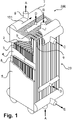
- Aluminum brazed plate fin heat exchangers are in figure 2 of the mentioned ISO 15547-2:3005 as well as on page 5 of the publication "The Standards of the Brazed Aluminum Plate-Fin Heat Exchanger Manufacturers'Association" of ALPEMA, 3rd edition 2010. An illustration that essentially corresponds to the illustrations there is in the attached figure 1 as prior art and is explained in advance in the following.
- the partially opened plate heat exchanger 300 according to the prior art is used for the heat exchange of five different process media A to E in the example shown.
- the plate heat exchanger 300 For heat exchange between the process media A to E, the plate heat exchanger 300 comprises a large number of ones arranged parallel to one another Separating plates 4 (referred to as parting sheets in the aforementioned publications, to which the following information in brackets also refers), between which heat exchange passages 1 are defined by structured plates with lamellae 3 (fins) for one of the process media A to E, which can thereby exchange heat with one another are formed.
- Separating plates 4 referred to as parting sheets in the aforementioned publications, to which the following information in brackets also refers
- the structural sheets with the lamellae 3 are typically folded or corrugated, flow channels being formed by the folds or corrugations, as also in FIG figure 1 of ISO 15547-2:3005.
- the provision of the structured plates with lamellae 3 offers the advantage of improved heat transfer, more targeted fluid guidance and an increase in the mechanical (tensile) strength.
- the process media A to E flow separately from one another, in particular through the separating plates 4, but can optionally pass through the latter in the case of perforated structured plates with lamellae 3.
- the individual passages 1 or the structured metal sheets with the lamellae 3 are each surrounded laterally by so-called sidebars 8, which, however, leave feed and removal openings 9 free.
- the sidebars 8 keep the separating plates 4 at a distance and ensure mechanical reinforcement of the pressure chamber.
- Reinforced cover plates 5 (cap sheets), which are arranged parallel to the separating plates 4, serve to close off at least two sides.
- headers 7 which are provided with nozzles 6 (nozzles)
- the process media A to E are supplied and discharged via feed and removal openings 9.
- distributor fins 2 distributed fins
- distributer lamellae 2 which guide the process media A to E from the passages 1 into the header 7 where they are collected and drawn off via the corresponding nozzles 6 .
- a cuboid here heat exchanger block 20 is formed overall, with under a "heat exchanger block" here the elements mentioned are to be understood without the header 7 and socket 6 in a connected state.
- the plate heat exchanger 300 can be formed from a plurality of corresponding cuboid heat exchanger blocks 20 connected to one another, in particular for manufacturing reasons.
- Corresponding plate heat exchangers 300 are brazed from aluminum.
- the individual passages 1, comprising the structural sheets with the lamellae 3, the other structural sheets with the distributor slats 2, the cover sheets 5 and the sidebars 8 are each provided with solder, stacked on top of one another or arranged accordingly and heated in an oven.
- the headers 7 and sockets 6 made of aluminum are welded onto the heat exchanger block 20 produced in this way. In this case, the headers 7 are welded onto the heat exchanger block 20 .
- the nozzles 6 can be welded to the headers 7.
- the sockets 6 are connected by means of transition connections with further pipelines, typically made of steel (in figure 1 not shown) connected via which the process media are supplied or discharged.
- the transition connection between the aluminum socket and the steel pipe can be made using explosion welding.
- Headers and nozzles made of aluminum have a relatively high wall thickness, which leads to long production times when completing the plate heat exchanger and can lead to failure of the explosion-welded transition connection due to thermal problems. So-called liquid metal embrittlement (LME) can also occur on an aluminum header.
- LME liquid metal embrittlement
- a header for a heat exchanger in particular a rib-plate heat exchanger, made from aluminum or from an aluminum alloy and a method for its production with the features of the independent claims.
- the header according to the invention is preferably intended for a brazed fin-plate heat exchanger made of aluminum or an aluminum alloy, but can in general also be used for other types of (aluminium/aluminium alloy) heat exchangers to which process fluids are supplied via a header and/or from which process fluids are discharged via a header, are used, i.e. are welded to them.
- aluminium/aluminium alloy aluminium/aluminium alloy
- the measure of using a steel or a steel composition for the wall element of the header allows the wall thickness to be reduced due to the higher strength of steel compared to aluminum, so that the manufacture of the plate heat exchanger is simplified. Only the aluminum body still has to be relatively thick. Furthermore, the steel wall panel does not have the problem of embrittlement when exposed to high temperature process media.
- the problem that aluminum or aluminum alloy cannot be joined to steel by fusion welding is solved by the transition region with the engagement structures, the production of which is achieved using an additive melting process.
- the form-fitting connection is achieved by the frame-engaging structure and the wall-engaging structure in their respective directions away from the Body or from the edge, have a variable thickness. These thickness variations are complementary to each other here, so that an interlocking is formed between the engagement structures, which ensures high strength of the connection.
- the transition area is manufactured using an additive manufacturing process that can be viewed as 3D printing.
- the material to be added or the starting material is applied directly to a workpiece.
- Starting materials can be provided in powder form or as wires.
- the feedstock is provided by a feed nozzle and melted by a focused heat or energy source such as a laser, arc, or electron beam.
- the melted material is then added to the workpiece, whereby if the starting material is provided in powder form, the powder can also first be applied to the workpiece (by means of feed nozzles) and melted there.
- the feed nozzle and heat source are mounted on a framework or robotic arm so that the feed nozzle and heat source are moveable and the molten feedstock can be added or applied to the workpiece at selected positions in three-dimensional space.
- the workpiece can be manufactured in layers.
- additive manufacturing enables the production of workpieces that have a complicated geometry and cannot be produced by other manufacturing processes, e.g. casting.
- this is built up in layers, starting from the base body of the frame or from the edge of the wall.
- the base body and/or the edge or the wall as a whole can also be produced by means of the additive manufacturing process. Due to the layered structure, the manufacture using an additive manufacturing process can be verified on the finished workpiece.
- Preferred additive manufacturing processes are build-up welding, additive manufacturing using direct energy deposition, arc build-up welding or arc-based additive manufacturing (WAAM), electron beam additive manufacturing, laser beam additive manufacturing, Plasma arc additive manufacturing.
- Other or overlapping examples of additive manufacturing processes are Selective Laser Sintering (SLS), Electron Beam Melting/ Electron Beam Additive Manufacturing (EBM/EBAM), Fused Filament Fabrication (FFF), melt layering (e.g. Fused Deposition Modeling, FDM), Stereolithography (STL , SLA), Digital Light Processing (DLP), Multi Jet Modeling (MJM), Polyjet process, Film Transfer Imaging (FTI), Laser Deposition Welding or Laminated Object Modeling (LOM).
- SLS Selective Laser Sintering
- EBM/EBAM Electron Beam Melting/ Electron Beam Additive Manufacturing
- FFF Fused Filament Fabrication
- melt layering e.g. Fused Deposition Modeling, FDM
- STL Stereolithography
- SLA
- an outer contact surface of the wall-engaging structure facing the frame-engaging structure is in contact with an outer contact surface of the frame-engaging structure facing the wall-engaging structure; more preferably, the outer contact surface of the wall-engaging structure is the entire outer surface of the wall-engaging structure facing the frame-engaging structure and/or the outer contact surface of the frame-engaging structure is the entire outer surface of the wall-engaging structure facing the wall-engaging structure.
- An aluminum alloy of the frame is preferably selected from the following: AI5083 (AIMg4.5Mn, material number 3.3547), Al6060 (AIMgSi, 3.3206), AISi10.
- the corrosion-resistant steel or the steel composition of the wall element is preferably selected from the following steel materials: stainless steels with the numbers AISI 316, AISI 304, AISI 321, AISI 347 according to the AISI classification (AISI: American Iron and Steel Institute) or with the material numbers 1.4401, 1.4301, 1.4541, 1.4550.
- a length of a continuous contact line formed in a cross section perpendicular to the circumferential direction between the frame engagement structure and the wall engagement structure is preferably at least 5 times, more preferably at least 10 times, a dimension of the extension of the wall engagement structure from the edge away.
- a two-dimensional contact surface is formed between the frame and wall engaging structures, corresponding to the external contact surfaces of the engaging structures.
- a section of this contact surface with a section plane perpendicular to the direction of rotation results in a one-dimensional line, which is referred to as the contact line.
- the dimension of the extension of the frame-engagement structure away from the base body could also be used as a comparative measure. These two dimensions are usually the same.
- the term “continuous” is intended to mean that only the length of one of the two lines formed by the cross-section should be used.
- the cross-section here corresponds to the cross-sectional view of figures 2 and 3 (see below).
- the frame-engaging structure comprises an inner-frame structure and an outer-frame structure between which the wall-engaging structure is formed; or the frame-engaging structure comprises an inner wall structure and an outer wall structure between which the frame-engaging structure is formed. This results in a connection that is difficult to break and results in a long contact path.
- the frame engagement structure preferably comprises at least one peripheral frame flank which extends away from the base body and on which projections are arranged laterally; the wall engaging structure comprising at least one peripheral wall flank extending from the rim and having projections disposed laterally thereon. More preferably, the projections arranged on the frame flank comprise sections extending in the direction of the base body and the projections arranged on the wall flank comprise sections extending in the direction of the edge. The projections arranged on the frame flank and the wall flank engage in one another so that a firm connection is produced.
- a sensor in particular a temperature sensor, is preferably arranged in the wall-engaging structure and/or the frame-engaging structure and/or on their contact surface. This enables the acquisition of sensor data in the transition area, in particular the temperature in the transition area can be monitored.
- the sensor can expediently be introduced during the additive manufacturing of the transition area.
- the wall-engaging structure and/or the frame-engaging structure have one spaced from the edge and one spaced from the body, respectively varying material composition.
- This is made possible by the additive manufacturing process, where, for example, if the starting material is provided in powder form, the mixing ratio of two or more powders is varied, or if the starting material is provided in wire form, the relative feed speed of two wires is varied.
- the frame has a welding surface which has a shape corresponding to a welding mating surface on a heat exchanger core of the (fin-plate) heat exchanger; further preferably, the welding surface is arranged on a side of the base body opposite to the frame engagement structure.
- the header can be easily welded to the heat exchanger block at this welding surface without having to provide further components for adapting the header to the heat exchanger block.
- connection opening is preferably provided in the wall.
- a continuing steel pipeline can be welded to the header, which is used for the supply and removal of a process medium
- the heat exchanger according to the invention which is preferably a fin-plate heat exchanger, comprises a header according to the above aspects, with the header being more preferably welded to a heat exchanger block of the heat exchanger.
- the method for manufacturing a header comprises providing an aluminum or aluminum alloy base body having a base body extending around a passage; providing a stainless steel wall having a rim extending around an opening conforming in shape to the passageway; Creating a transition area by means of an additive manufacturing process, wherein a peripheral frame engagement structure extending from the base body is created on the frame and a peripheral wall engagement structure that extends from the edge and is complementary to the frame engagement structure is created on the wall, so that the frame - engagement structure is in engagement with the wall engagement structure and a circumferential positive connection is formed between the frame and the wall element.
- the provision of the base body preferably includes producing the base body by means of the additive manufacturing method; and/or providing the wall includes at least partially producing the wall by means of the additive manufacturing process.
- the frame engaging structure is made of aluminum or an aluminum alloy and the wall engaging structure is made of stainless steel; wherein layers are applied in the additive manufacturing process and when layers are applied, the aluminum or the aluminum alloy is used in the direction transverse to the direction of rotation alternately with the corrosion-resistant steel within a layer to be applied.
- a composition of the aluminum alloy and/or a composition of the stainless steel is/are varied over time or over a series of layers. This variation of the compositions allows a constant transition of material properties to be achieved.
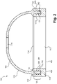
- figure 2 10 shows a cross-sectional view of a header 100 according to the invention figure 1 this can be used as a header 7, with the viewing direction perpendicular to the plane of the arrow 101 in figure 1 corresponds and the cut was made approximately at the level of the position of the socket 6 or the opening into which it opens.
- the elements of figure 2 are not necessarily drawn to scale, in particular the size of individual elements may be adjusted in order to make the essential structure of the header clearly recognizable.
- the header 100 comprises a frame or header frame 103 and a wall element or header wall element 105 .
- the frame 103 consists of aluminum or an aluminum alloy and has a base body 104 .
- the frame or its base body in the figure can have an essentially rectangular shape (like the header 7 in figure 1 ) have, for example essentially consist of four strips that form a rectangle, the corners can be rounded.
- An oval shape or the like is also conceivable here.
- the frame or the base body can also be curved, ie not run along a plane parallel to the viewing direction of the figure. This is advantageous when the corresponding mating surface of the heat exchanger block has a curved shape.
- the frame 103 or its base body 104 also has a welding surface 108 which is designed to be welded to a corresponding counter-welding surface which is provided on the heat exchanger block of the fin-plate heat exchanger (not shown).
- the welding surface 108 is thus shaped in accordance with the welding counter-surface. If the counter-welding surface has a curved shape, the welding surface can also be correspondingly curved, ie it follows the curvature of the counter-welding surface.
- a flat welding surface 108 is shown in the figure for the sake of simplicity. It is also possible for the frame or the base body to be curved overall, so that the base body has a constant height perpendicular to the welding surface in the circumferential direction.
- the frame 103 or its main body 104 surrounds a passage 110.
- the term "direction of rotation" refers to the direction (circumferential) around the passage 110 or the opening 114 (see below).
- the wall element 105 is made of a corrosion-resistant steel or a stainless steel and includes a wall 106.
- the wall 106 has a curved shape, with an edge 112 of the wall surrounding an opening 114 whose geometry (shape and size) to the geometry of the passage 110 of the base body is adapted or corresponds to this.
- a connection opening 116 is also provided in the wall 106 .
- This connection opening can be connected in a similar way as in figure 1 a socket can be welded on or a further steel pipeline can be welded on directly, since the wall is made of steel. If a nozzle is provided, it should be made of corrosion-resistant steel. In principle, it is also possible to form a socket-like attachment directly in the wall.
- the wall thus surrounds a cavity with the opening 114 and the connection opening 116.
- the opening surrounded by the edge serves for the connection to the frame and via this to a heat exchanger block and the connection opening serves for the connection to further pipelines.
- a frame-engaging structure 122 is provided on the frame and a wall-engaging structure 124 is provided on the edge 112 of the wall 106 in a transition region 120 (between frame and wall). These extend away from the base and rim, respectively, and extend circumferentially around the passageway 110 and opening 114, respectively.
- the frame engagement structure is located on a side of the base opposite the weld area.
- the frame engagement structure 122 is related to the their complementary wall-engaging structure 124 to form a positive wall-to-frame connection with the wall-engaging structure 122 and the frame-engaging structure in contact at a contact surface 126 .
- the term "complementary" is to be understood here in particular as meaning that the geometry (i.e.
- the shape and dimension of the outer surface of the wall-engaging structure facing the frame-engaging structure is essentially the same (except for minor differences which result from the outer surfaces adjoining each other lying) is the geometry of the outer surface of the frame-engaging structure facing the wall-engaging structure.
- the outer surfaces facing the respective other engagement structure thus form the contact surface 126 between the frame and wall engagement structure.
- the form-fitting connection is correspondingly designed to be fluid-tight. In the cross section shown, the contact surface 126 forms a contact line 128.
- the frame engagement structure 122 consists of the in figure 2 illustrated embodiment of an (inner) inner frame structure 122a and an (outer) outer frame structure 122b, between which the wall-engaging structure 124 is arranged.
- a reverse arrangement is also possible here, ie that the wall-engaging structure consists of an inner wall structure and an outer wall structure, between which the frame-engaging structure is arranged.
- Inside/outside refers to the inside of the passage or opening.
- the frame engagement structure and the wall engagement structure are each formed by at least one peripheral frame flank (here two: one each for the frame inner structure and outer structure) or wall flank (here one) which extends from the base body or extending away from the edge, with projections being provided on the flanks (frame flanks and wall flanks), preferably circumferential, which engage in one another. These projections result in a thickness of the frame engagement structure and wall engagement structure that varies with the distance from the base body or from the edge.
- the wall flank 130 and the projections 132 located thereon are provided with reference symbols by way of example.
- the frame engagement structure 122 is made of aluminum or an aluminum alloy, such as the same as the main body of the frame.
- the wall engaging structure 124 is made of a corrosion resistant steel such as same steel as the wall and its edge.
- the frame-engagement structure and the wall-engagement structure can each be in one piece, in particular materially connected, with the frame or the wall, in this sense they can be regarded as components or sections of the frame or the wall.
- the frame then includes the (frame) base body and the frame engagement structure, with the expression that the frame engagement structure extends away from the frame is to be understood as meaning that the frame engagement structure extends away from the base body.
- the header 100 is produced at least in the transition area 120 by means of an additive manufacturing process; the other sections of the frame and/or the wall element (i.e. the base body and/or the wall) can also be produced by means of an additive manufacturing process.
- the additive manufacturing process makes it possible to design the frame engagement structure and the wall engagement structure in the transition area in such a way that that these are in contact with one another at the contact surface, so that a fluid-tight connection of the wall to the frame is created.
- a sensor 142 arranged in the transition region for example a temperature sensor, is shown as an example, together with the sensor line routed to the outside.
- the sensor is expediently arranged in the transition area during the additive manufacturing of the latter.
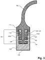
- FIG. 12 shows a partial cross-sectional view of a header according to the invention, which illustrates a preferred embodiment of the transition region or the engagement structures.
- This embodiment essentially corresponds to the embodiment of FIG figure 2 , whereby here the transition area is only shown on one side.
- the difference lies in the different design of the frame-engaging structure and wall-engaging structure 124.
- the frame-engaging structure again has an inner frame structure 122a and an outer frame structure 122b.
- the engagement structures are again formed by flanks with projections located thereon.
- frame engagement structure 124 is by a frame edge 134 and lateral projections 136 located thereon. These projections 136 extend partially towards the rim 112 (ie, opposite the flank extending away from the rim).
- the (complementary) projections of the wall-engaging structure extend towards the main body 104 of the frame.
- a frame flank 138 of the frame engagement structure (more precisely the frame inner structure 122a) and a projection 140 located thereon are provided with reference symbols.
- the cut surface of the frame-engaging structure or the wall-engaging structure breaks down into a plurality of circumferential partial cut surfaces when the cut is at the height of the sections extending in the direction of the frame or the edge of the respective projections takes place.
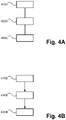
- Figures 4A and 4B show flow charts of preferred embodiments of the method according to the invention.
- Figure 4A the basic steps of the procedure are shown without a specific order.
- the method includes in step 410A providing the aluminum or aluminum alloy body having a body extending around a passageway, and in step 420A providing a stainless steel wall having a rim extending around an opening defined in its shape corresponds to the passage.
- the base body and/or the wall can be produced partially or entirely using an additive manufacturing process.
- the transition region is created using the additive manufacturing process.
- the related to the figures 2 and 3 explained engagement structures generated. A circumferential frame engagement structure extending from the base body is thus produced on the frame and a circumferential wall engagement structure that extends from the edge and is complementary to the frame engagement structure is produced on the wall, so that the frame engagement structure can be connected to the wall engagement structure in Engagement is and a circumferential positive connection between the frame and the wall element is formed.
- step 410B represents the step of preparing the base body, corresponding to step 410A of FIG Figure 4A .
- Step 420B represents the step of providing the wall, corresponding to step 420A.
- Step 430B represents the creation of the transition region corresponding to step 430A.
- providing the wall occurs after creating the transition region (step 430B).
- the procedure can be as follows: First (step 410B) the base body is provided, for example this can be done using the additive manufacturing process. Subsequently (step 430B), the transition region with the engagement structures is produced using the additive manufacturing method, starting from the base body.
- step 420B the wall is provided, in particular by the additive manufacturing method starting from the transition area.
- the entire header can advantageously be produced by means of the additive manufacturing method.
- the reverse order can also be used here (not shown), ie the wall is provided first, then the transition area is created starting from the edge of the wall and finally the base body is created starting from the transition area.
- the additive manufacturing process is expediently used for all steps.
Landscapes
- Engineering & Computer Science (AREA)
- Physics & Mathematics (AREA)
- Mechanical Engineering (AREA)
- Thermal Sciences (AREA)
- General Engineering & Computer Science (AREA)
- Plasma & Fusion (AREA)
- Optics & Photonics (AREA)
- Chemical & Material Sciences (AREA)
- Manufacturing & Machinery (AREA)
- Materials Engineering (AREA)
- Heat-Exchange Devices With Radiators And Conduit Assemblies (AREA)
Priority Applications (1)
| Application Number | Priority Date | Filing Date | Title |
|---|---|---|---|
| EP21020224.8A EP4080152A1 (fr) | 2021-04-21 | 2021-04-21 | En-tête pour un échangeur de chaleur et procédé de fabrication |
Applications Claiming Priority (1)
| Application Number | Priority Date | Filing Date | Title |
|---|---|---|---|
| EP21020224.8A EP4080152A1 (fr) | 2021-04-21 | 2021-04-21 | En-tête pour un échangeur de chaleur et procédé de fabrication |
Publications (1)
| Publication Number | Publication Date |
|---|---|
| EP4080152A1 true EP4080152A1 (fr) | 2022-10-26 |
Family
ID=75639644
Family Applications (1)
| Application Number | Title | Priority Date | Filing Date |
|---|---|---|---|
| EP21020224.8A Withdrawn EP4080152A1 (fr) | 2021-04-21 | 2021-04-21 | En-tête pour un échangeur de chaleur et procédé de fabrication |
Country Status (1)
| Country | Link |
|---|---|
| EP (1) | EP4080152A1 (fr) |
Citations (5)
| Publication number | Priority date | Publication date | Assignee | Title |
|---|---|---|---|---|
| DE4229393A1 (de) * | 1992-09-03 | 1994-03-10 | Rudolf Goerlich | Wärmetauscher mit einer Steckverbindung |
| US20040000397A1 (en) * | 2001-04-25 | 2004-01-01 | William Curtindale | Metal heat exchanger tank and method of forming same |
| US6886629B2 (en) * | 2000-05-09 | 2005-05-03 | Linde Akiengesellschaft | Plate heat exchanger |
| EP2696062B1 (fr) * | 2012-08-09 | 2018-05-16 | MAHLE Behr GmbH & Co. KG | Caloporteur |
| US20190219337A1 (en) * | 2018-01-18 | 2019-07-18 | United Technologies Corporation | Hybrid additive manufactured heat exchanger with tubes |
-
2021
- 2021-04-21 EP EP21020224.8A patent/EP4080152A1/fr not_active Withdrawn
Patent Citations (5)
| Publication number | Priority date | Publication date | Assignee | Title |
|---|---|---|---|---|
| DE4229393A1 (de) * | 1992-09-03 | 1994-03-10 | Rudolf Goerlich | Wärmetauscher mit einer Steckverbindung |
| US6886629B2 (en) * | 2000-05-09 | 2005-05-03 | Linde Akiengesellschaft | Plate heat exchanger |
| US20040000397A1 (en) * | 2001-04-25 | 2004-01-01 | William Curtindale | Metal heat exchanger tank and method of forming same |
| EP2696062B1 (fr) * | 2012-08-09 | 2018-05-16 | MAHLE Behr GmbH & Co. KG | Caloporteur |
| US20190219337A1 (en) * | 2018-01-18 | 2019-07-18 | United Technologies Corporation | Hybrid additive manufactured heat exchanger with tubes |
Similar Documents
| Publication | Publication Date | Title |
|---|---|---|
| EP3265739B1 (fr) | Élément chauffant imprimé en 3d pour un échangeur de chaleur à plaques | |
| EP1995544B1 (fr) | Echangeur thermique, en particulier refroidisseur d'air de suralimentation ou refroidisseur de gaz d'échappement pour un moteur à combustion interne d'un véhicule automobile et son procédé de fabrication | |
| DE102011105045B3 (de) | Verfahren zur Herstellung eines Bauteils mittels selektivem Laserschmelzen | |
| DE69214635T2 (de) | Waermetauscher | |
| EP3077751B1 (fr) | Échangeur de chaleur et procédé de fabrication d'un échangeur de chaleur | |
| DE112008001782B4 (de) | Wärmetauscher | |
| DE112020001433T5 (de) | Temperierplatte mit einem mikrostrukturierten Flüssigkeitskanal, insbesondere für Kraftfahrzeuge | |
| DE102010056073A1 (de) | Heißkanaldüse | |
| EP0660064A2 (fr) | Joint pour relier un tube à une plaque tubulaire d'un échangeur de chaleur | |
| DE102020118836B3 (de) | Fertigungsverfahren für ein formgebendes Werkzeugteil eines Formwerkzeugs | |
| EP3700702B1 (fr) | Elément d'échange de chaleur et procédé de fabrication d'un élément d'échange de chaleur | |
| EP4226224B1 (fr) | Procédé de fabrication d'un composant pour un dispositif technique | |
| EP2696062B1 (fr) | Caloporteur | |
| WO2021063661A1 (fr) | Procédé de soudage laser et ensemble de composants | |
| EP4059713A1 (fr) | Procédé de fabrication d'un dispositif technique | |
| EP4436734A1 (fr) | Procédé pour la production d'un composant, et composant corrélativement produit | |
| DE102016117766A1 (de) | Additive Fertigung unter Verwendung von gegossenem Band-Superlegierungsmaterial | |
| WO2019121985A1 (fr) | Contenant de fluide en forme de plaque et procédé pour la fabrication d'un contenant de fluide en forme de plaque | |
| DE102015100255A1 (de) | Rohrbündel-Wärmetauschergruppe und Apparat, insbesondere Reaktor für die Erzeugung von Melamin umfassend eine solche Wärmetauschergruppe | |
| DE102020000274A1 (de) | Verfahren zur Herstellung eines Rippen-Platten-Wärmetauschers | |
| DE102016214959A1 (de) | Temperiereinheit für ein elektronisches Bauelement und Verfahren zu dessen Herstellung | |
| DE102020002546A1 (de) | Verfahren zur additven Fertigung eines Werkstücks | |
| WO2019137757A1 (fr) | Pale d'aube de turbine, aube de turbine et procédé de fabrication associé | |
| AT18094U1 (de) | Gasdurchlassmodul für einen hochtemperaturofen | |
| EP4172546B1 (fr) | Procédé de fabrication d'un échangeur de chaleur à plaque à nervures et échangeur de chaleur à plaque à nervures |
Legal Events
| Date | Code | Title | Description |
|---|---|---|---|
| PUAI | Public reference made under article 153(3) epc to a published international application that has entered the european phase |
Free format text: ORIGINAL CODE: 0009012 |
|
| STAA | Information on the status of an ep patent application or granted ep patent |
Free format text: STATUS: THE APPLICATION HAS BEEN PUBLISHED |
|
| AK | Designated contracting states |
Kind code of ref document: A1 Designated state(s): AL AT BE BG CH CY CZ DE DK EE ES FI FR GB GR HR HU IE IS IT LI LT LU LV MC MK MT NL NO PL PT RO RS SE SI SK SM TR |
|
| STAA | Information on the status of an ep patent application or granted ep patent |
Free format text: STATUS: THE APPLICATION IS DEEMED TO BE WITHDRAWN |
|
| 18D | Application deemed to be withdrawn |
Effective date: 20230427 |