EP4080156A1 - Optischer oder magnetischer massstab mit wählbarem nullpunkt der thermischen ausdehnung - Google Patents
Optischer oder magnetischer massstab mit wählbarem nullpunkt der thermischen ausdehnung Download PDFInfo
- Publication number
- EP4080156A1 EP4080156A1 EP22168628.0A EP22168628A EP4080156A1 EP 4080156 A1 EP4080156 A1 EP 4080156A1 EP 22168628 A EP22168628 A EP 22168628A EP 4080156 A1 EP4080156 A1 EP 4080156A1
- Authority
- EP
- European Patent Office
- Prior art keywords
- scale
- holder
- optical
- machine
- grating
- Prior art date
- Legal status (The legal status is an assumption and is not a legal conclusion. Google has not performed a legal analysis and makes no representation as to the accuracy of the status listed.)
- Granted
Links
Images


Classifications
-
- G—PHYSICS
- G01—MEASURING; TESTING
- G01D—MEASURING NOT SPECIALLY ADAPTED FOR A SPECIFIC VARIABLE; ARRANGEMENTS FOR MEASURING TWO OR MORE VARIABLES NOT COVERED IN A SINGLE OTHER SUBCLASS; TARIFF METERING APPARATUS; MEASURING OR TESTING NOT OTHERWISE PROVIDED FOR
- G01D5/00—Mechanical means for transferring the output of a sensing member; Means for converting the output of a sensing member to another variable where the form or nature of the sensing member does not constrain the means for converting; Transducers not specially adapted for a specific variable
- G01D5/26—Mechanical means for transferring the output of a sensing member; Means for converting the output of a sensing member to another variable where the form or nature of the sensing member does not constrain the means for converting; Transducers not specially adapted for a specific variable characterised by optical transfer means, i.e. using infrared, visible, or ultraviolet light
- G01D5/32—Mechanical means for transferring the output of a sensing member; Means for converting the output of a sensing member to another variable where the form or nature of the sensing member does not constrain the means for converting; Transducers not specially adapted for a specific variable characterised by optical transfer means, i.e. using infrared, visible, or ultraviolet light with attenuation or whole or partial obturation of beams of light
- G01D5/34—Mechanical means for transferring the output of a sensing member; Means for converting the output of a sensing member to another variable where the form or nature of the sensing member does not constrain the means for converting; Transducers not specially adapted for a specific variable characterised by optical transfer means, i.e. using infrared, visible, or ultraviolet light with attenuation or whole or partial obturation of beams of light the beams of light being detected by photocells
- G01D5/347—Mechanical means for transferring the output of a sensing member; Means for converting the output of a sensing member to another variable where the form or nature of the sensing member does not constrain the means for converting; Transducers not specially adapted for a specific variable characterised by optical transfer means, i.e. using infrared, visible, or ultraviolet light with attenuation or whole or partial obturation of beams of light the beams of light being detected by photocells using displacement encoding scales
- G01D5/34707—Scales; Discs, e.g. fixation, fabrication, compensation
-
- B—PERFORMING OPERATIONS; TRANSPORTING
- B23—MACHINE TOOLS; METAL-WORKING NOT OTHERWISE PROVIDED FOR
- B23Q—DETAILS, COMPONENTS, OR ACCESSORIES FOR MACHINE TOOLS, e.g. ARRANGEMENTS FOR COPYING OR CONTROLLING; MACHINE TOOLS IN GENERAL CHARACTERISED BY THE CONSTRUCTION OF PARTICULAR DETAILS OR COMPONENTS; COMBINATIONS OR ASSOCIATIONS OF METAL-WORKING MACHINES, NOT DIRECTED TO A PARTICULAR RESULT
- B23Q17/00—Arrangements for observing, indicating or measuring on machine tools
- B23Q17/24—Arrangements for observing, indicating or measuring on machine tools using optics or electromagnetic waves
- B23Q17/2452—Arrangements for observing, indicating or measuring on machine tools using optics or electromagnetic waves for measuring features or for detecting a condition of machine parts, tools or workpieces
-
- B—PERFORMING OPERATIONS; TRANSPORTING
- B23—MACHINE TOOLS; METAL-WORKING NOT OTHERWISE PROVIDED FOR
- B23Q—DETAILS, COMPONENTS, OR ACCESSORIES FOR MACHINE TOOLS, e.g. ARRANGEMENTS FOR COPYING OR CONTROLLING; MACHINE TOOLS IN GENERAL CHARACTERISED BY THE CONSTRUCTION OF PARTICULAR DETAILS OR COMPONENTS; COMBINATIONS OR ASSOCIATIONS OF METAL-WORKING MACHINES, NOT DIRECTED TO A PARTICULAR RESULT
- B23Q17/00—Arrangements for observing, indicating or measuring on machine tools
- B23Q17/24—Arrangements for observing, indicating or measuring on machine tools using optics or electromagnetic waves
- B23Q17/248—Arrangements for observing, indicating or measuring on machine tools using optics or electromagnetic waves using special electromagnetic means or methods
-
- G—PHYSICS
- G01—MEASURING; TESTING
- G01D—MEASURING NOT SPECIALLY ADAPTED FOR A SPECIFIC VARIABLE; ARRANGEMENTS FOR MEASURING TWO OR MORE VARIABLES NOT COVERED IN A SINGLE OTHER SUBCLASS; TARIFF METERING APPARATUS; MEASURING OR TESTING NOT OTHERWISE PROVIDED FOR
- G01D5/00—Mechanical means for transferring the output of a sensing member; Means for converting the output of a sensing member to another variable where the form or nature of the sensing member does not constrain the means for converting; Transducers not specially adapted for a specific variable
- G01D5/12—Mechanical means for transferring the output of a sensing member; Means for converting the output of a sensing member to another variable where the form or nature of the sensing member does not constrain the means for converting; Transducers not specially adapted for a specific variable using electric or magnetic means
- G01D5/244—Mechanical means for transferring the output of a sensing member; Means for converting the output of a sensing member to another variable where the form or nature of the sensing member does not constrain the means for converting; Transducers not specially adapted for a specific variable using electric or magnetic means influencing characteristics of pulses or pulse trains; generating pulses or pulse trains
- G01D5/24428—Error prevention
- G01D5/24433—Error prevention by mechanical means
- G01D5/24442—Error prevention by mechanical means by mounting means
-
- G—PHYSICS
- G01—MEASURING; TESTING
- G01D—MEASURING NOT SPECIALLY ADAPTED FOR A SPECIFIC VARIABLE; ARRANGEMENTS FOR MEASURING TWO OR MORE VARIABLES NOT COVERED IN A SINGLE OTHER SUBCLASS; TARIFF METERING APPARATUS; MEASURING OR TESTING NOT OTHERWISE PROVIDED FOR
- G01D5/00—Mechanical means for transferring the output of a sensing member; Means for converting the output of a sensing member to another variable where the form or nature of the sensing member does not constrain the means for converting; Transducers not specially adapted for a specific variable
- G01D5/26—Mechanical means for transferring the output of a sensing member; Means for converting the output of a sensing member to another variable where the form or nature of the sensing member does not constrain the means for converting; Transducers not specially adapted for a specific variable characterised by optical transfer means, i.e. using infrared, visible, or ultraviolet light
- G01D5/32—Mechanical means for transferring the output of a sensing member; Means for converting the output of a sensing member to another variable where the form or nature of the sensing member does not constrain the means for converting; Transducers not specially adapted for a specific variable characterised by optical transfer means, i.e. using infrared, visible, or ultraviolet light with attenuation or whole or partial obturation of beams of light
- G01D5/34—Mechanical means for transferring the output of a sensing member; Means for converting the output of a sensing member to another variable where the form or nature of the sensing member does not constrain the means for converting; Transducers not specially adapted for a specific variable characterised by optical transfer means, i.e. using infrared, visible, or ultraviolet light with attenuation or whole or partial obturation of beams of light the beams of light being detected by photocells
- G01D5/347—Mechanical means for transferring the output of a sensing member; Means for converting the output of a sensing member to another variable where the form or nature of the sensing member does not constrain the means for converting; Transducers not specially adapted for a specific variable characterised by optical transfer means, i.e. using infrared, visible, or ultraviolet light with attenuation or whole or partial obturation of beams of light the beams of light being detected by photocells using displacement encoding scales
- G01D5/34746—Linear encoders
- G01D5/34753—Carriages; Driving or coupling means
-
- G—PHYSICS
- G01—MEASURING; TESTING
- G01D—MEASURING NOT SPECIALLY ADAPTED FOR A SPECIFIC VARIABLE; ARRANGEMENTS FOR MEASURING TWO OR MORE VARIABLES NOT COVERED IN A SINGLE OTHER SUBCLASS; TARIFF METERING APPARATUS; MEASURING OR TESTING NOT OTHERWISE PROVIDED FOR
- G01D2205/00—Indexing scheme relating to details of means for transferring or converting the output of a sensing member
- G01D2205/10—Detecting linear movement
Definitions
- the present invention relates to an optical or magnetic scale with selectable position of the zero thermal expansion point, also named Fixed Expansion Point, or simply FEP.
- machine As known to the man skilled in the art, optical or magnetic scales are frequently used on tool machines and operating machines (hereinafter generically referred to as "machines", for the sake of brevity) for measuring with great accuracy the linear movements of carriages and tables.
- a micro-engraved scale-grating is provided on a steel or glass support, which support is scanned by a position transducer converting into an electric signal the alternation of the reflecting/diffusing or transparent/opaque markings encountered while moving along the same scale-grating.
- the magnetic band support bearing a succession of north/south poles, detected by the position transducer is made of steel.
- optical scales provided with a scale-grating support made of steel although it should be clearly intended that the present invention is equally addressed to both types of scales, i.e., optical scales provided with a scale-grating support made of steel or glass, and magnetic scales provided with a magnetic band support made of steel.
- the scale-grating needs to be protected from impacts and dirt by being housed in a stout aluminium case, hereinafter referred to as scale-holder, which also serves as a guide and a support for the scale-grating and as a means for fixing the optical scale to the machine.
- scale-holder a stout aluminium case
- magnetic scales are much less sensitive to dirt than optical scales, they also are usually housed and protected inside a scale-holder.
- Tool machines and numerically controlled machining centres (CNC) of modern concept employ temperature sensors and a software for correcting the measurement errors, which are periodically reset.
- CNC numerically controlled machining centres
- Such systems are expensive, need a certain time for reset operations, and cannot be applied to every type of machine.
- a valid solution, even for the most advanced machines, is therefore that of employing optical scales having a scale-grating support made of steel, especially when the scale-grating is considerably long (over 2-3 m).
- Optical scales in fact, are usually fixed to the carriages, tables, or machine structures.
- the scale-holder must be allowed to stretch and to shrink as a function of the room temperature, freely spreading its thermal expansion, which is very different from that of the machine parts to which the scale-holder is usually applied.
- the scale-holder must be perfectly integral with the machine at least in one point, because it is not acceptable that over time the scale-holder could "migrate” dragging the scale-grating and making it take different positions from the measuring system initial zero setting.
- the technical problem addressed by the present invention is therefore that of providing a measuring system, specifically an optical scale, wherein the scale-grating can be fixed to the scale-holder and the scale-holder can be fixed to the machine in such a way that both the scale-grating and the scale-holder can freely expand - consequently to temperature variations - in a mutually independent way and yet according to mutually consistent directions, and wherein the operator can easily adapt the optical scale to the specific type of machine on which the optical scale is installed, and to the specific machining process being carried out.
- both the elastic adhesive and the fixing screw clamps with shape elasticity impart an elastic reaction force on the scale-grating support and the scale-holder, which force is directly proportional to the extent of the thermal expansion. Therefore, the above said elements do not freely expand, but undergo progressive compression due to the elastic reaction force of their fixing devices, which compression obviously is greater the longer the optical scale.
- said elastic reaction force varies with temperatures and time - due to phenomena of aging of the adhesive and hysteresis or fatigue of the fixing screw clamps with shape elasticity - and thus it is not possible to exactly evaluate the final deformation of the scale-grating and the scale-holder at a given temperature; this ultimately resulting in random measuring errors that lower the quality of high-precision machining operations.
- Object of the present invention is therefore to provide, in addition to the FEP points of the scale-grating and scale-holder, a plurality of other fastening means positioned in several points between the scale-holder and the machine and between the scale-grating and the scale-holder.
- Said fastening means should be apt to ensure the correct cross position of these elements, stably and accurately, while allowing at the same time their free longitudinal slipping under thermal expansion.
- the linear thermal expansion of the scale-grating and the scale-holder could so occur independently from each other and without any negative interference from said fastening means.
- a further object of the present invention is then to provide a special way for selecting the different possible FEP points of the scale-grating support wherein - contrarily to what provided in the above cited prior art - neither a preventive drilling operation of said scale-grating support nor a preventive alignment operation of the same with respect to the scale-holder is requested for the activation of the selected FEP point.
- optical scale of the present invention offers, as already per se known from the above cited prior art document, an easy selection of the FEP positions, according to the machine on which it is installed, allowing to optimize the accuracy of the processes carried out at temperatures different from the reference temperature of 20°C.
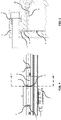
- the FEP in a vertical milling machine the FEP is positioned at the centre of the longitudinal axis, as well as at the centre of the transverse axis, and it is therefore correct that the optical scale FEP is also in its central position.
- the FEPs of the vertical axis and of the descent axis of the milling machine quill are positioned laterally.
- the optical scale too had its FEP in a lateral position, i.e., a position consistent with that of the FEP of the machine.
- a workpiece is in fact clamped by the chuck jaws, and the longitudinal guides and the workpiece have a thermal expansion from said chuck towards the tailstock.
- the FEP of the longitudinal axis of the parallel lathe is therefore "under the head", i.e., in correspondence with the chuck which clamps the workpiece.
- the FEP of an optical scale measuring the displacement of the carriage moving along guides which are subject to thermal expansion likewise the workpiece, should be in correspondence of the chuck, i.e., positioned laterally, left side/right-side, depending on whether the optical scale is mounted on the front/rear of the machine bed.
- a traditional optical scale with a centrally positioned FEP would not thermally expand consistently with the thermal expansion of the machine and workpiece.
- the FEP of the transverse axis of the parallel lathe is centrally positioned, i.e., coincident with the chuck and workpiece rotational centre, and therefore an optical scale with a centrally positioned FEP is in this case appropriate to measure the position of the machining tool along such axis.
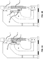
- Screw clamping fasteners 7 impart a transversal elastic-thrust, provided by spring contrast means, which is sufficient to ensure that the scale-holder P continuously rests on the machine table and that any movement in the two crosswise directions be prevented, thus ensuring the maintenance over time of the alignment tolerances between the various modules M of the optical scale.
- the tightening of the elastic-thrust clamping fasteners 7 is adjusted so that the resulting elastic-thrust is such as to allow the scale-holder P to freely slip in the longitudinal direction so spreading its linear thermal expansion when the ambient temperature changes - which thermal expansion significantly differ from that of the machine, due to their different materials - without causing distortions or misalignments of the scale-holder P itself.
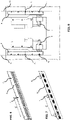
- threaded through-holes 9 are provided crosswise the scale-holder P, ending within the inside of the scale-holder P as can be clearly seen in the cross-sectional view of Fig. 5 , in correspondence of the steel strip 2 forming the scale-grating support.
- the through-holes 9 are arranged throughout the scale-holder P according to a constant pitch C which can be the same pitch of the slots 6.
- a pressure pin 10 is screwed in a selected one of said through-holes 9 until said steel strip 2 is intercepted by the tip of the pressure pin 10 and locked in position against a scale-holder wall lying behind, which position thus becomes the scale-grating FEP.
- This FEP fixing mode does not require any preventive drilling of the scale-grating support for housing a fixing screw. Furthermore, this FEP fixing mode can be quickly activated under any circumstance, also when the scale-grating support and the scale-holder are under thermal expansion, while in the device of the prior art, under these same conditions, the through holes on the scale-grating support and the scale-holder which house the fixing screw might be no more aligned at the selected FEP position.
- An optical scale is usually supplied with centrally positioned FEPs of both the scale-holder P and the scale-grating.
- FEPs of both the scale-holder P and the scale-grating.
- any other arrangement of the FEPs is possible, when considered useful for the purpose of improving the machining accuracy of the machine.
- the optical scale of the present invention in fact, provides for the maximum flexibility in setting the position of the FEPs of both the scale-holder P and the scale-grating, which can thus be at the same or at different positions.
- the whole operation can be carried out in a few minutes and without requiring any special equipment.
- optical scale of the present invention has been described with reference to a preferred fastening system of the scale-grating or magnetic band support inside the scale-holder P.
- all the essential features of the invention can also be applied to optical scales having different fastening systems of said support, provided that such fastening systems include a single fixed point of the support, wherein the support is made integral with the scale-holder by means, for example, of a screw or other mechanical fastening system or inelastic adhesive, while the remaining part of the support is held in position inside the scale-holder P by use of free longitudinal slipping means.
Landscapes
- Physics & Mathematics (AREA)
- General Physics & Mathematics (AREA)
- Optics & Photonics (AREA)
- Engineering & Computer Science (AREA)
- Mechanical Engineering (AREA)
- Electromagnetism (AREA)
- Optical Transform (AREA)
- Transmission And Conversion Of Sensor Element Output (AREA)
- Light Guides In General And Applications Therefor (AREA)
Applications Claiming Priority (1)
| Application Number | Priority Date | Filing Date | Title |
|---|---|---|---|
| IT102021000010292A IT202100010292A1 (it) | 2021-04-22 | 2021-04-22 | Riga ottica o magnetica con posizione selezionabile del punto nullo di dilatazione termica |
Publications (3)
| Publication Number | Publication Date |
|---|---|
| EP4080156A1 true EP4080156A1 (de) | 2022-10-26 |
| EP4080156B1 EP4080156B1 (de) | 2025-08-06 |
| EP4080156C0 EP4080156C0 (de) | 2025-08-06 |
Family
ID=77126919
Family Applications (1)
| Application Number | Title | Priority Date | Filing Date |
|---|---|---|---|
| EP22168628.0A Active EP4080156B1 (de) | 2021-04-22 | 2022-04-15 | Optischer oder magnetischer massstab mit wählbarem nullpunkt der thermischen ausdehnung |
Country Status (4)
| Country | Link |
|---|---|
| EP (1) | EP4080156B1 (de) |
| CN (1) | CN115229562A (de) |
| ES (1) | ES3042205T3 (de) |
| IT (1) | IT202100010292A1 (de) |
Cited By (1)
| Publication number | Priority date | Publication date | Assignee | Title |
|---|---|---|---|---|
| CN118936283A (zh) * | 2024-10-12 | 2024-11-12 | 上飞飞机装备制造(成都)有限公司 | 一种回转体零件的同轴度测量设备与方法 |
Citations (3)
| Publication number | Priority date | Publication date | Assignee | Title |
|---|---|---|---|---|
| EP0264801A1 (de) * | 1986-10-18 | 1988-04-27 | Firma Carl Zeiss | Halterung für Mass- und Formverkörperungen |
| EP0566828A2 (de) * | 1992-04-18 | 1993-10-27 | Dr. Johannes Heidenhain GmbH | Temperaturkompensierte Längenmesseinrichtung |
| EP3657134A1 (de) * | 2018-11-21 | 2020-05-27 | Fagor Arrasate, S.Coop. | Opto-elektronische messvorrichtung |
Family Cites Families (6)
| Publication number | Priority date | Publication date | Assignee | Title |
|---|---|---|---|---|
| DE4424649C2 (de) * | 1994-07-13 | 1997-11-20 | Heidenhain Gmbh Dr Johannes | Positionsmeßeinrichtung |
| JP3452689B2 (ja) * | 1995-06-20 | 2003-09-29 | シグマテック株式会社 | 位置決め装置 |
| ES2285390T3 (es) * | 2004-11-23 | 2007-11-16 | Fagor, S.Coop | Codificador lineal con compensacion de temperatura. |
| CN100554888C (zh) * | 2006-03-27 | 2009-10-28 | 廊坊开发区莱格光电仪器有限公司 | 一种密封式超长标尺光栅传感器 |
| DE102009044917A1 (de) * | 2009-09-23 | 2011-04-07 | Dr. Johannes Heidenhain Gmbh | Längenmesseinrichtung |
| JP6359340B2 (ja) * | 2014-05-27 | 2018-07-18 | 株式会社ミツトヨ | スケール及び光学式エンコーダ |
-
2021
- 2021-04-22 IT IT102021000010292A patent/IT202100010292A1/it unknown
-
2022
- 2022-04-15 EP EP22168628.0A patent/EP4080156B1/de active Active
- 2022-04-15 ES ES22168628T patent/ES3042205T3/es active Active
- 2022-04-20 CN CN202210419321.XA patent/CN115229562A/zh active Pending
Patent Citations (4)
| Publication number | Priority date | Publication date | Assignee | Title |
|---|---|---|---|---|
| EP0264801A1 (de) * | 1986-10-18 | 1988-04-27 | Firma Carl Zeiss | Halterung für Mass- und Formverkörperungen |
| EP0566828A2 (de) * | 1992-04-18 | 1993-10-27 | Dr. Johannes Heidenhain GmbH | Temperaturkompensierte Längenmesseinrichtung |
| US5375338A (en) | 1992-04-18 | 1994-12-27 | Dr. Johannes Heidenhain Gmbh | Length measurement device |
| EP3657134A1 (de) * | 2018-11-21 | 2020-05-27 | Fagor Arrasate, S.Coop. | Opto-elektronische messvorrichtung |
Cited By (1)
| Publication number | Priority date | Publication date | Assignee | Title |
|---|---|---|---|---|
| CN118936283A (zh) * | 2024-10-12 | 2024-11-12 | 上飞飞机装备制造(成都)有限公司 | 一种回转体零件的同轴度测量设备与方法 |
Also Published As
| Publication number | Publication date |
|---|---|
| EP4080156B1 (de) | 2025-08-06 |
| ES3042205T3 (en) | 2025-11-19 |
| IT202100010292A1 (it) | 2021-07-22 |
| CN115229562A (zh) | 2022-10-25 |
| EP4080156C0 (de) | 2025-08-06 |
Similar Documents
| Publication | Publication Date | Title |
|---|---|---|
| JP2515853B2 (ja) | 位置測定装置 | |
| US5979238A (en) | Strip-shaped resiliently flexible measuring tape for length--or angle-measuring devices | |
| JPH10506474A (ja) | 長さ測定装置を固定する装置 | |
| JPS6337208A (ja) | 測長機 | |
| US5375338A (en) | Length measurement device | |
| JP2006502419A (ja) | 空間参照システム | |
| EP4080156B1 (de) | Optischer oder magnetischer massstab mit wählbarem nullpunkt der thermischen ausdehnung | |
| CN111664323B (zh) | 带有主承载件、布置在主承载件上的中间承载件和布置在中间承载件上的比例尺的组件 | |
| US5511321A (en) | Linear encoder | |
| US5558557A (en) | Three axis control for machine tool | |
| JPS63281009A (ja) | 位置測定装置用の組み付け方法及びその方法を実施するための装置 | |
| GB2112943A (en) | Coordinate measuring machine | |
| US4492033A (en) | Linear scale type displacement measuring instrument | |
| US4012030A (en) | Fixture for precision positioning of work pieces | |
| US10391601B2 (en) | Position measuring device for use on a machine tool | |
| US5303458A (en) | Method and apparatus for detecting and compensating thermal growth in machine tools | |
| US3740856A (en) | Flexure mounting for friction wheel measuring devices | |
| US5142792A (en) | Position measuring device | |
| RU2348952C2 (ru) | Устройство для прецизионного линейного перемещения оптических элементов | |
| US5924214A (en) | Length measuring apparatus for measuring the relative position of two objects | |
| CN211373443U (zh) | 一种直径公差测量表 | |
| US5729218A (en) | Encoder | |
| US4364179A (en) | Statically balanced inspection probe assembly | |
| US5931428A (en) | Bracket for clamping a measuring instrument and stand for supporting the same | |
| JPH0240168B2 (de) |
Legal Events
| Date | Code | Title | Description |
|---|---|---|---|
| PUAI | Public reference made under article 153(3) epc to a published international application that has entered the european phase |
Free format text: ORIGINAL CODE: 0009012 |
|
| STAA | Information on the status of an ep patent application or granted ep patent |
Free format text: STATUS: THE APPLICATION HAS BEEN PUBLISHED |
|
| AK | Designated contracting states |
Kind code of ref document: A1 Designated state(s): AL AT BE BG CH CY CZ DE DK EE ES FI FR GB GR HR HU IE IS IT LI LT LU LV MC MK MT NL NO PL PT RO RS SE SI SK SM TR |
|
| STAA | Information on the status of an ep patent application or granted ep patent |
Free format text: STATUS: REQUEST FOR EXAMINATION WAS MADE |
|
| 17P | Request for examination filed |
Effective date: 20230224 |
|
| RBV | Designated contracting states (corrected) |
Designated state(s): AL AT BE BG CH CY CZ DE DK EE ES FI FR GB GR HR HU IE IS IT LI LT LU LV MC MK MT NL NO PL PT RO RS SE SI SK SM TR |
|
| GRAP | Despatch of communication of intention to grant a patent |
Free format text: ORIGINAL CODE: EPIDOSNIGR1 |
|
| STAA | Information on the status of an ep patent application or granted ep patent |
Free format text: STATUS: GRANT OF PATENT IS INTENDED |
|
| INTG | Intention to grant announced |
Effective date: 20250319 |
|
| GRAS | Grant fee paid |
Free format text: ORIGINAL CODE: EPIDOSNIGR3 |
|
| GRAA | (expected) grant |
Free format text: ORIGINAL CODE: 0009210 |
|
| STAA | Information on the status of an ep patent application or granted ep patent |
Free format text: STATUS: THE PATENT HAS BEEN GRANTED |
|
| AK | Designated contracting states |
Kind code of ref document: B1 Designated state(s): AL AT BE BG CH CY CZ DE DK EE ES FI FR GB GR HR HU IE IS IT LI LT LU LV MC MK MT NL NO PL PT RO RS SE SI SK SM TR |
|
| REG | Reference to a national code |
Ref country code: GB Ref legal event code: FG4D |
|
| REG | Reference to a national code |
Ref country code: CH Ref legal event code: EP |
|
| REG | Reference to a national code |
Ref country code: DE Ref legal event code: R096 Ref document number: 602022018724 Country of ref document: DE |
|
| REG | Reference to a national code |
Ref country code: IE Ref legal event code: FG4D |
|
| U01 | Request for unitary effect filed |
Effective date: 20250825 |
|
| U07 | Unitary effect registered |
Designated state(s): AT BE BG DE DK EE FI FR IT LT LU LV MT NL PT RO SE SI Effective date: 20250829 |
|
| REG | Reference to a national code |
Ref country code: ES Ref legal event code: FG2A Ref document number: 3042205 Country of ref document: ES Kind code of ref document: T3 Effective date: 20251119 |
|
| PG25 | Lapsed in a contracting state [announced via postgrant information from national office to epo] |
Ref country code: IS Free format text: LAPSE BECAUSE OF FAILURE TO SUBMIT A TRANSLATION OF THE DESCRIPTION OR TO PAY THE FEE WITHIN THE PRESCRIBED TIME-LIMIT Effective date: 20251206 |
|
| PG25 | Lapsed in a contracting state [announced via postgrant information from national office to epo] |
Ref country code: NO Free format text: LAPSE BECAUSE OF FAILURE TO SUBMIT A TRANSLATION OF THE DESCRIPTION OR TO PAY THE FEE WITHIN THE PRESCRIBED TIME-LIMIT Effective date: 20251106 |
|
| PG25 | Lapsed in a contracting state [announced via postgrant information from national office to epo] |
Ref country code: HR Free format text: LAPSE BECAUSE OF FAILURE TO SUBMIT A TRANSLATION OF THE DESCRIPTION OR TO PAY THE FEE WITHIN THE PRESCRIBED TIME-LIMIT Effective date: 20250806 |
|
| PG25 | Lapsed in a contracting state [announced via postgrant information from national office to epo] |
Ref country code: GR Free format text: LAPSE BECAUSE OF FAILURE TO SUBMIT A TRANSLATION OF THE DESCRIPTION OR TO PAY THE FEE WITHIN THE PRESCRIBED TIME-LIMIT Effective date: 20251107 |
|
| PG25 | Lapsed in a contracting state [announced via postgrant information from national office to epo] |
Ref country code: PL Free format text: LAPSE BECAUSE OF FAILURE TO SUBMIT A TRANSLATION OF THE DESCRIPTION OR TO PAY THE FEE WITHIN THE PRESCRIBED TIME-LIMIT Effective date: 20250806 |
|
| PG25 | Lapsed in a contracting state [announced via postgrant information from national office to epo] |
Ref country code: RS Free format text: LAPSE BECAUSE OF FAILURE TO SUBMIT A TRANSLATION OF THE DESCRIPTION OR TO PAY THE FEE WITHIN THE PRESCRIBED TIME-LIMIT Effective date: 20251106 |
|
| U20 | Renewal fee for the european patent with unitary effect paid |
Year of fee payment: 5 Effective date: 20260224 |
|
| PG25 | Lapsed in a contracting state [announced via postgrant information from national office to epo] |
Ref country code: SM Free format text: LAPSE BECAUSE OF FAILURE TO SUBMIT A TRANSLATION OF THE DESCRIPTION OR TO PAY THE FEE WITHIN THE PRESCRIBED TIME-LIMIT Effective date: 20250806 |
|
| PGFP | Annual fee paid to national office [announced via postgrant information from national office to epo] |
Ref country code: GB Payment date: 20260224 Year of fee payment: 5 |
|
| PGFP | Annual fee paid to national office [announced via postgrant information from national office to epo] |
Ref country code: TR Payment date: 20260306 Year of fee payment: 5 |