EP4080257A1 - Entriegelungsvorrichtung für optische module, optisches modul und optische kommunikationsvorrichtung - Google Patents
Entriegelungsvorrichtung für optische module, optisches modul und optische kommunikationsvorrichtung Download PDFInfo
- Publication number
- EP4080257A1 EP4080257A1 EP19958725.4A EP19958725A EP4080257A1 EP 4080257 A1 EP4080257 A1 EP 4080257A1 EP 19958725 A EP19958725 A EP 19958725A EP 4080257 A1 EP4080257 A1 EP 4080257A1
- Authority
- EP
- European Patent Office
- Prior art keywords
- optical module
- unlocking
- component
- disposed
- optical
- Prior art date
- Legal status (The legal status is an assumption and is not a legal conclusion. Google has not performed a legal analysis and makes no representation as to the accuracy of the status listed.)
- Granted
Links
Images


Classifications
-
- G—PHYSICS
- G02—OPTICS
- G02B—OPTICAL ELEMENTS, SYSTEMS OR APPARATUS
- G02B6/00—Light guides; Structural details of arrangements comprising light guides and other optical elements, e.g. couplings
- G02B6/24—Coupling light guides
- G02B6/42—Coupling light guides with opto-electronic elements
- G02B6/4201—Packages, e.g. shape, construction, internal or external details
- G02B6/4274—Electrical aspects
- G02B6/4284—Electrical aspects of optical modules with disconnectable electrical connectors
-
- G—PHYSICS
- G02—OPTICS
- G02B—OPTICAL ELEMENTS, SYSTEMS OR APPARATUS
- G02B6/00—Light guides; Structural details of arrangements comprising light guides and other optical elements, e.g. couplings
- G02B6/24—Coupling light guides
- G02B6/36—Mechanical coupling means
- G02B6/38—Mechanical coupling means having fibre to fibre mating means
- G02B6/3807—Dismountable connectors, i.e. comprising plugs
- G02B6/3869—Mounting ferrules to connector body, i.e. plugs
- G02B6/387—Connector plugs comprising two complementary members, e.g. shells, caps, covers, locked together
-
- G—PHYSICS
- G02—OPTICS
- G02B—OPTICAL ELEMENTS, SYSTEMS OR APPARATUS
- G02B6/00—Light guides; Structural details of arrangements comprising light guides and other optical elements, e.g. couplings
- G02B6/24—Coupling light guides
- G02B6/36—Mechanical coupling means
- G02B6/38—Mechanical coupling means having fibre to fibre mating means
- G02B6/3807—Dismountable connectors, i.e. comprising plugs
- G02B6/3833—Details of mounting fibres in ferrules; Assembly methods; Manufacture
- G02B6/3855—Details of mounting fibres in ferrules; Assembly methods; Manufacture characterised by the method of anchoring or fixing the fibre within the ferrule
- G02B6/3858—Clamping, i.e. with only elastic deformation
-
- G—PHYSICS
- G02—OPTICS
- G02B—OPTICAL ELEMENTS, SYSTEMS OR APPARATUS
- G02B6/00—Light guides; Structural details of arrangements comprising light guides and other optical elements, e.g. couplings
- G02B6/24—Coupling light guides
- G02B6/36—Mechanical coupling means
- G02B6/38—Mechanical coupling means having fibre to fibre mating means
- G02B6/3807—Dismountable connectors, i.e. comprising plugs
- G02B6/389—Dismountable connectors, i.e. comprising plugs characterised by the method of fastening connecting plugs and sockets, e.g. screw- or nut-lock, snap-in, bayonet type
- G02B6/3893—Push-pull type, e.g. snap-in, push-on
-
- G—PHYSICS
- G02—OPTICS
- G02B—OPTICAL ELEMENTS, SYSTEMS OR APPARATUS
- G02B6/00—Light guides; Structural details of arrangements comprising light guides and other optical elements, e.g. couplings
- G02B6/24—Coupling light guides
- G02B6/42—Coupling light guides with opto-electronic elements
- G02B6/4201—Packages, e.g. shape, construction, internal or external details
- G02B6/4274—Electrical aspects
- G02B6/4277—Protection against electromagnetic interference [EMI], e.g. shielding means
Definitions
- This application relates to the field of optical communication technologies, and in particular, to an optical module unlocking apparatus, an optical module, and an optical communication device.
- Pluggable optical modules are mainly connected between hosts and optical cables, and can perform conversion between optical signals and electrical signals, to implement communication.
- optical communication technologies people have increasingly high requirements on function diversity of the optical modules.
- a cage is disposed on a host for accommodation of an optical module, and an elastomer is disposed on the cage.
- the optical module with an unlocking mechanism is pluggably disposed in the cage.
- the unlocking mechanism includes a housing for installing a circuit board and a handle disposed on the housing.
- One connection arm is disposed on each of two sides of the housing, and the handle is connected to the two connection arms.
- the elastomer may abut against the connection arm to lock the optical module.
- the optical module can be unlocked by pulling the handle.
- the connection arm moves relative to the housing to push the elastomer, so as to unlock the optical module.
- a reset spring is disposed on an inner side of each connection arm close to the circuit board, so that the connection arm can be restored to an original position after the handle is released.
- An objective of this application is to provide an optical module unlocking apparatus, an optical module, and an optical communication device, to resolve small installation space in a circuit board and a component in a current optical module.
- this application discloses an optical module unlocking apparatus.
- the apparatus includes: a housing, including a base and a mounting portion connected to one end of the base, where the base is provided with an accommodation area for installing a circuit board and a component, and the mounting portion is provided with at least one optical port for connecting an optical cable; an unlocking component, including an unlocking arm movably connected to the housing, where the unlocking arm is provided with an abutment portion for abutting against an elastomer of a cage, and the unlocking component is configured to push the unlocking arm outwards relative to the housing in an insertion direction under an action of external force, to separate the abutment portion from the elastomer; and an elastic component, disposed on an outer side surface of the mounting portion and outside the accommodation area, where two ends of the elastic component are respectively connected to the mounting portion and the unlocking component, the elastic component can deform under the action of the external force, and the unlocking arm moves inwards relative to the housing in the insertion direction under an action
- the elastic component is limited in a side area on which the optical port is disposed, the area in which the optical port is located is independent of the accommodation area in which the circuit structure is installed on the base, and the elastic component does not extend to the accommodation area. This can prevent occupying installation space of a circuit structure, increase a volume of the accommodation area, increase an area of the circuit board, increase types and a quantity of components, and improve function diversity of the optical module.
- the elastic component is disposed at one end of the mounting portion in a first direction, where the first direction is perpendicular to the circuit board. In this way, space at the top or the bottom of the optical port in the first direction may be properly used, to increase installation space of the elastic component.
- the elastic component may be close to an axial surface of the optical module, so that a stall phenomenon can be reduced.
- a first connection portion is disposed on the unlocking component
- a second connection portion is disposed on the mounting portion
- one end of the elastic component abuts against the first connection portion
- the other end of the elastic component abuts against the second connection portion.
- a groove with a first opening is disposed on an outer side surface of the mounting portion, the elastic component is accommodated in the groove, and one end of the groove in the insertion direction has a groove wall, where the groove wall forms a second connection portion.
- the first connection portion includes a baffle plate extending into the groove, and the baffle plate is disposed opposite to the groove wall.
- the elastic component is installed by using the groove. In this case, the elastic component does not protrude from the top surface of the mounting portion, space of the mounting portion is properly used, and a size of the optical module is not increased, so that the size of the optical module can meet a disposing requirement.
- the other end of the groove in the insertion direction has a second opening in communication with the first opening.
- the second opening may allow the baffle plate to move forward and backward in the insertion direction in the groove, and may increase space in which the elastic component is compressed or extended.
- the mounting portion includes a top wall, a bottom wall, and two oppositely disposed side walls connected between the top wall and the bottom wall.
- the top wall and the bottom wall are disposed opposite to each other in the first direction, and the bottom wall is connected to the base.
- the top wall, the bottom wall, and the side walls enclose the optical port, and the groove is disposed on the top wall. In this way, space at the top of the optical port in the first direction may be properly used, to increase installation space of the elastic component.
- a notch in communication with the optical port is further disposed at an edge of the bottom wall away from the accommodation area, where the notch is configured to accommodate a pressing portion of the optical cable. This provides sufficient operation space for the pressing portion 310 and increases the installation space of the elastic component.
- the unlocking component includes a connection plate connected to the unlocking arm, where the connection plate is located outside the first opening, and the baffle plate is connected to the connection plate. This can improve fastening strength of the baffle plate, and prevent the baffle plate from deforming in a process of compressing the elastic component.
- the baffle plate may further assist in fastening the elastic component, and prevent the elastic component from flying out of the groove after being compressed.
- the baffle plate includes a bending section and an extension section.
- the bending section is connected between the connection plate and the extension section, and the extension section is disposed opposite to the groove wall.
- the bending section is an arc section.
- the bending section is disposed obliquely relative to the connection plate. This can implement smooth transition between the connection plate and the extension section, avoid stress concentration, and improve strength of the baffle plate.
- an accommodation hole is formed in the connection plate, the baffle plate is connected to a wall of the accommodation hole, and an orthographic projection of the baffle plate on the connection plate is at least partially located in the accommodation hole.
- the accommodation hole includes a gap formed at an edge of the connection plate, which facilitates processing.
- a proximity interface for installing the elastic component is further disposed at a position, corresponding to the first opening, of the connection plate, which facilitates installing.
- connection plate includes a body and a cover portion connected to the body, where the body is connected to the unlocking arm, and the cover portion extends in the insertion direction to cover the first opening exposed outside the body.
- the optical module has a compact structure.
- the cover portion and the body can jointly cover the first opening, preventing the elastic component 130 from flying out of the groove after being compressed.
- each groove accommodates one elastic component.
- the second direction is perpendicular to the first direction and the insertion direction.
- a plurality of elastic components may be mutually redundant. When one of the elastic components is faulty, another elastic component may restore the unlocking component to an initial state, improving reliability of the optical module unlocking apparatus.
- a partition portion is disposed in space enclosed by the top wall, the bottom wall, and the side walls, where the partition portion divides the space into a plurality of optical ports that are spaced in a direction perpendicular to the side walls.
- the elastic component is disposed at one end in the first direction. This can prevent occupying space of the optical port in the second direction, properly use the space in the mounting portion, and improve function diversity of the optical module.
- each groove is located on the top of one optical port in the first direction.
- the two optical ports may be symmetrically disposed relative to the axial surface of the optical module, further reducing the stall phenomenon of the unlocking component.
- the side walls and the partition portion extend into the accommodation area in the first direction.
- the partition portion has a first protruding section protruding from the top wall in the first direction.
- the side walls have second protruding sections protruding from the top wall in the first direction.
- a first area enclosed between one second protruding section and the first protruding section is used to accommodate a transmit component.
- a second area enclosed between the other second protruding section and the first protruding section is used to accommodate a receive component.
- the transmit component and the receive component may be respectively disposed corresponding to one optical port, which facilitates signal transmission and reduces a loss.
- the two unlocking arms re spaced in the second direction perpendicular to the first direction, so that the optical module is securely fastened to the cage.
- the unlocking component further includes a handle connected to the unlocking arm, and the handle protrudes outwards from the housing in the insertion direction. This facilitates removing the optical module.
- a positioning pin is further disposed on the base, a sliding slot extending in the insertion direction is disposed on the unlocking arm, the positioning pin is inserted into the sliding slot, and the sliding slot and the positioning pin can slide relative to each other in the insertion direction.
- the unlocking arm can move relative to the housing in the insertion direction, to push the elastomer, so as to implement unlocking.
- the housing further includes a cover body on the base.
- the cover body and the base enclose the accommodation area. This facilitates installing the circuit structure to the accommodation area.
- a heat sink may be further disposed on the base.
- the heat sink may be in contact with the component on the circuit board, to dissipate heat, so that the optical module can run stably.
- a support portion configured to support the transmit component and the receive component may be further disposed on the base.
- the support portion may have a support slot that matches a side surface of the transmit component or the receive component, to improve stability of the transmit component and the receive component.
- this application discloses an optical module, including a component, a circuit board, and an optical module unlocking apparatus.
- the component is installed on a circuit board, and the circuit board and the component are installed in an accommodation area of a housing.
- the optical module disclosed in this application can increase an area of the circuit board, increase types and a quantity of components, and improve function diversity of the optical module.
- this application discloses an optical communication device, including a cage and an optical module.
- An elastomer is disposed on the cage, the optical module is inserted into the cage, and the elastomer presses against an abutment portion of the optical module.
- the optical communication device disclosed in this application can increase an area of the circuit board, increase types and a quantity of components, and improve function diversity of the optical communication device.
- the elastic component is limited in a side area on which the optical port is disposed, the area in which the optical port is located is independent of the accommodation area in which the circuit structure is installed on the base, and the elastic component does not extend to the accommodation area. This can prevent occupying installation space of a circuit structure, increase a volume of the accommodation area, increase an area of the circuit board, increase types and a quantity of components, and improve function diversity of the optical module.
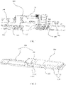
- FIG. 1 is a schematic diagram of a structure of an optical communication device according to an embodiment of this application.
- This embodiment provides an optical communication device, which may include a cage 200 and an optical module 100.
- the optical module 100 is inserted into the cage 200.
- optical communication devices such as an optical transceiver, an optical fiber transceiver, a switch, an optical network adapter, an optical fiber high-speed dome camera, a base station, and a repeater.
- the optical module 100 may be inserted into each cage 200.
- the optical module 100 may be used in the optical communication device.
- One end of the optical module 100 in an insertion direction can be inserted into the cage 200 of the optical communication device, and the other end of the optical module 100 may connect to an optical cable 300, to perform mutual conversion between an optical signal and an electrical signal.
- the optical module 100 may be encapsulated in a plurality of modes, for example, a quad small form-factor pluggable (QSFP), a quad small form-factor pluggable double density (QSFP-DD), a 10 gigabit small form-factor pluggable (XFP), and a small form-factor pluggable (SFP).
- QSFP quad small form-factor pluggable
- QSFP-DD quad small form-factor pluggable double density
- XFP 10 gigabit small form-factor pluggable
- SFP small form-factor pluggable
- the insertion direction may be a direction of inserting or removing the optical module 100, for example, a left-right direction in FIG. 1 .
- a direction (from left to right in FIG. 1 ) of inserting the optical module 100 is defined as a direction facing inward in the insertion direction
- a direction (from right to left in FIG. 1 ) of removing the optical module is defined as a direction facing outward in the insertion direction.
- the optical module 100 may include an optical module unlocking apparatus and a circuit structure installed in the optical module unlocking apparatus.
- the optical module 100 may be inserted into, removed from, and fastened to the cage 200 by using the optical module unlocking apparatus.
- the optical module unlocking apparatus may include a housing 110 and an unlocking component 120.
- the circuit structure may be installed in the housing 110.
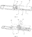
- FIG. 2 is a schematic diagram of a structure of an optical module according to an embodiment of this application.
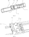
- FIG. 3 is a schematic diagram of the structure in FIG. 2 with a cover plate removed.
- FIG. 5 is a schematic diagram of the structure in FIG. 3 with a circuit board and a component removed.
- the housing 110 may include a base 111 and a mounting portion 112 connected to one end of the base 111. An accommodation area is provided in the base 111 for installing the circuit structure.
- the mounting portion 112 is provided with at least one optical port 114 for connecting an optical cable 300.
- the base 111 may be of a plate structure, top space of the base 111 may have an accommodation area, and the circuit structure may be installed in the accommodation area.
- the base 111 may be a hollow shell structure, space enclosed by the base 111 may form an accommodation area, and the circuit structure may be installed in the accommodation area.
- the circuit structure may be a main electronic component for implementing optical-toelectrical conversion in the optical module 100.
- the circuit structure may include a circuit board 140 and a component 150 connected to the circuit board 140.
- the component 150 may include a plurality of electronic components. This is not limited herein. Both the circuit board 140 and the component 150 are installed in the accommodation area.
- the housing 110 further includes a cover body 115 on the base 111, and the cover body 115 and the base 111 encloses the accommodation area.
- the base 111 may be connected to the cover body 115 through screw connection or clamping. This facilitates installing the circuit structure to the accommodation area.
- a heat sink 116 may be further disposed on the base 111.
- the heat sink 116 may be in contact with the component on the circuit board 140, to dissipate heat, so that the optical module 100 can run stably.
- the mounting portion 112 may be disposed at an outer end of the base 111 in an insertion direction.
- the mounting portion 112 may be integrally formed with the base 111.
- At least one optical port 114 may be disposed inside the mounting portion 112. The optical port 114 may extend in the insertion direction.
- An end of the optical cable 300 may have a connector, and the connector may be inserted into the optical port 114.
- a pressing portion 310 may be disposed on a connector of the optical cable 300, and a fastener clamped with the optical port 114 may be further disposed on the connector.
- the pressing portion 310 may be pressed to retract the fastener, so that the connector can be smoothly inserted into the optical port 114.
- the pressing portion 310 is released, and the fastener may be clamped onto the optical port 114, so that the connector and the optical module 100 securely connected. This can prevents the optical cable 300 from shaking relative to the optical module 100, which may affect signal transmission.
- a notch 1124 may be further disposed on the mounting portion 112.
- the notch 1124 may be in communication with the optical port 114 and may be configured to accommodate the pressing portion 310 of the optical cable 300.
- an unlocking component 120 includes an unlocking arm 121 movably connected to the housing 110.
- the unlocking arm 121 may extend in the insertion direction, and may be disposed at one end of the housing 110 in a second direction.
- the second direction may be parallel to a direction of the circuit board, and perpendicular to the insertion direction.
- two unlocking arms 121 may be disposed on the optical module 100, and the two unlocking arms 121 are respectively located at two ends of the housing in the second direction, so that the optical module 100 and the cage 200 are securely fastened.
- the unlocking arm 121 can move relative to the housing 110 in the insertion direction.
- a positioning pin 1111 is further disposed on the base 111, the unlocking arm 121 may extend in the insertion direction, and a sliding slot 1211 that extends in the insertion direction is disposed on the unlocking arm 121, the positioning pin 1111 is inserted into the sliding slot 1211, and the sliding slot 1211 and the positioning pin 1111 can slide relative to each other in the insertion direction.
- the sliding slot 1211 may be disposed on the base 111, and the positioning pin 1111 is disposed on the unlocking arm 121.
- the positioning pin 1111 or the sliding slot 1211 may be disposed on the mounting portion 112, and the sliding slot 1211 or the positioning pin 1111 may correspondingly be disposed on the unlocking arm 121.
- An abutment portion 122 that abuts against an elastomer 210 of a cage 200 may be disposed on the unlocking arm 121.
- a protrusion may be disposed at one end of the unlocking arm 121.
- a recessed abutment portion 122 may be formed between the protrusion and the unlocking arm.
- a bump on the elastomer may be clamped onto a dent to fasten the optical module 100 and the cage 200.
- the optical module 100 When the optical module 100 is inserted, the optical module 100 may be pushed into the cage 200. In this case, the elastomer 210 may abut against the abutment portion 122 to implement fastening.
- the elastomer may pull the unlocking component 120.
- the unlocking component 120 may push the unlocking arm 121 outwards relative to the housing 110 in the insertion direction under an action of external force.
- a protrusion on the unlocking arm 121 may push the elastomer 210, to separate the abutment portion 122 from the elastomer 210.
- the unlocking component 120 may be further pulled, so that the entire optical module 100 moves outward, to separate from the cage 200.
- the unlocking component 120 further includes a handle 125 connected to the unlocking arm 121, and the handle 125 protrudes outwards from the housing 110 in the insertion direction.
- the handle 125 may have a plurality of shapes, for example, a ring shape or a square shape. Two ends of the handle 125 may be respectively connected to two unlocking arms 121. In this way, when the handle is pulled, pulling force may be evenly transferred to the two unlocking arms 121.
- FIG. 4 is a schematic exploded view of FIG. 2 .
- the unlocking component 120 has a displacement away from the housing 110 in the insertion direction.
- an elastic component 130 may be disposed in the optical module unlocking apparatus to restore the unlocking component 120.
- the elastic component 130 may be an elastic structure such as a spiral spring, and two ends of the elastic component 130 may be respectively connected to the mounting portion and the unlocking component.
- the elastic component 130 can deform under an action of external force.
- the deformation may be tensile deformation or compressive deformation.
- the unlocking arm 121 moves inwards relative to the housing 110 in the insertion direction under an action of elastic force of the elastic component 130.
- the elastic component 130 is disposed on an outer side surface of the mounting portion 112.
- the outer side surface may be an outer surface surrounding the optical port on the mounting portion 112.
- the elastic component 130 may be located outside the accommodation area.
- a spring is disposed in space for installing a circuit board and a component inside a connection arm.
- the spring occupies installation space of the component and the circuit board, resulting in a limited area of the circuit board and a limited quantity of components, and low function diversity.
- the elastic component 130 is limited in a side area on which the optical port 114 is disposed, the area in which the optical port 114 is located is independent of the accommodation area in which the circuit structure is installed on the base 111, and the elastic component 130 does not extend to the accommodation area. This can prevent installation space of a circuit structure from being occupied, increase a volume of the accommodation area, increase an area of the circuit board 140, increase types and a quantity of components 150, and improve function diversity of the optical module 100.
- the elastic component 130 is disposed at one end of the mounting portion 112 in the first direction. It may be understood that, when the optical module 100 is inserted into the cage, the mounting portion 112 may be located outside the cage 200. Due to limitations of a size and a specification of the cage 200, a size of the optical module 100 inserted into the cage 200 needs to match that of the cage 200, that is, a size between two unlocking arms 121 located at two ends of the housing 110 in the second direction is strictly limited. Therefore, stricter requirements are imposed on a size of the mounting portion 112 in the second direction, and lower requirements are imposed on a size of the mounting portion 112 in the first direction.
- the elastic component 130 is disposed at one end of the mounting portion 112 in the first direction. In this way, space at the top or the bottom of the optical port in the first direction may be properly used, to increase installation space of the elastic component 130.
- one spring is disposed inside each connection arm in the related technology.
- pulling forces of two connection arms are different due to a position on which the force is applied, and a compression length of the spring is also different.
- a stall phenomenon is likely to occur.
- the elastic component 130 is disposed at one end of the mounting portion 112 in the first direction, so that the elastic component may be close to an axial surface of the optical module 100, reducing the stall phenomenon.
- a first connection portion is disposed on the unlocking component 120, and a second connection portion is disposed on the mounting portion 112.
- One end of the elastic component 130 abuts against the first connection portion, and the other end of the elastic component 130 abuts against the second connection portion.
- the first connection portion and the second connection portion may be spaced in the insertion direction.
- the elastic component 130 may be a compression spring, and two ends of the elastic component 130 may respectively abut against the first connection portion and the second connection portion.
- the elastic component 130 is connected by abutting. This structure is simple and easy to implement.
- the first connection portion moves outwards relative to the second connection portion, and the elastic component 130 may be compressed and deformed under an action of pressure.
- the external force disappears, and the second connection portion may also move relative to the first connection portion under an elastic action of the elastic component 130, so that the unlocking component 120 is restored to an initial state when the elastic component 130 is not compressed.
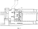
- FIG. 6 is an enlarged view of a local part of FIG. 5 .
- FIG. 7 is a schematic diagram of the structure in FIG. 6 at another angle.
- FIG. 8 is a schematic diagram of the structure in FIG. 6 with a connection plate removed.
- a groove 113 with a first opening is disposed on an outer side surface of a mounting portion 112.
- the first opening is a top opening of the groove 113 in FIG. 8 .
- An elastic component 130 is accommodated in the groove 113, and one end of the groove 113 in an insertion direction has a groove wall 1131, where the groove wall 1131 forms a second connection portion.
- a first connection portion includes a baffle plate 123 extending into the groove 113, and a baffle plate 123 is disposed opposite to the groove wall 1131.
- the elastic component 130 is installed by using the groove 113. In this case, the elastic component 130 does not protrude from the top surface of the mounting portion 112, space of the mounting portion 112 is properly used, and a size of the optical module 100 is not increased, so that the size of the optical module 100 can meet a disposing requirement.
- the uncompressed natural length of the elastic component 130 may be less than the length of the groove 113 in the insertion direction, so that the elastic component 130 may be always located in the groove 113 during deformation, to prevent the spring from extending to an accommodation area to occupy installation space of a component 150 and a circuit board 140.
- the other end of the groove 113 in the insertion direction has a second opening in communication with the first opening.
- the second opening may be an opening on the right side of the groove 113.
- the second opening and the groove wall 1131 may be separately disposed opposite to each other in the insertion direction.
- the second opening may allow the baffle plate 123 to move forward and backward in the insertion direction in the groove 113, and may increase space in which the elastic component 130 is compressed or extended.
- the mounting portion 112 includes a top wall 1121, a bottom wall 1122, and two oppositely disposed side walls 1123 connected between the top wall 1121 and the bottom wall 1122.
- the top wall 1121 and the bottom wall 1122 are disposed opposite to each other in a first direction.
- Two side walls 1123 may be disposed opposite to each other in a second direction.
- the bottom wall 1122 is connected to a base 111.
- the top wall 1121, the bottom wall 1122, and the side walls 1123 enclose an optical port 114, and the groove 113 is disposed on the top wall 1121. In this way, space at the top of the optical port 114 in the first direction may be properly used, to increase installation space of the elastic component 130.
- the top wall 1121, the bottom wall 1122, and the side walls 1123 each may be a plate-like or block-like structure with a specific thickness. Their thicknesses may be the same or different, which is not limited herein.
- the top wall 1121, the bottom wall 1122, and the side walls 1123 may be integrally formed.
- bosses or dents of various shapes may be disposed on the top wall 1121, the bottom wall 1122, and the side walls 1123, specifically based on an actual structure.
- the bottom wall 1122 may be connected to the base 111.
- the bottom wall 1122 and the base 111 may be connected in sequence in the insertion direction.
- the bottom wall 1122 and the base 111 may also be integrally formed.
- Two unlocking arms 121 may be respectively located outside the two side walls 1123.
- the groove 113 is disposed on the top wall 1121. Certainly, in another embodiment, the groove 113 may also be disposed in the bottom wall 1122.
- a notch 1124 is further disposed at an edge of the bottom wall 1122 away from the accommodation area, where the notch 1124 is configured to accommodate a pressing portion 310. Due to existence of the notch 1124, space for disposing the elastic component 130 on the bottom wall 1122 is reduced. In this case, the elastic component 130 is installed in the groove 113 of the top wall 1121, so that a mounting area of the elastic component 130 may be enlarged, facilitating disposition and installation of the elastic component.
- the unlocking component 120 includes a connection plate 124 connected to the unlocking arms 121.
- the connection plate 124 may extend in the second direction, and two ends of the connection plate 124 in the second direction may be respectively connected to the two unlocking arms 121.
- the connection plate 124 may be located outside the first opening, that is, above the top wall 1121.
- the baffle plate 123 is connected to the connection plate 124. This can improve fastening strength of the baffle plate 123, and prevent the baffle plate 123 from deforming in a process of compressing the elastic component 130.
- the baffle plate 123 may further assist in fastening the elastic component 130, and prevent the elastic component 130 from flying out of the groove 113 after being compressed.
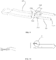
- FIG. 9 is a schematic diagram of the structure of an unlocking component in FIG. 4 .
- FIG. 10 is a schematic cross-sectional view of the structure in FIG. 9 .
- FIG. 11 is an enlarged view at C in FIG. 10 .
- the baffle plate 123 may include a bending section 1231 and an extension section 1232.
- the bending section 1231 is connected between the connection plate 124 and the extension section 1232, and the extension section 1232 is disposed opposite to each other.
- Two ends of the elastic component 130 may abut between the groove wall 1131 and the extension section 1232.
- the baffle plate 123 may be separately installed on the connection plate 124, or may be integrally formed with the connection plate 124.
- the bending section 1231 and the extension section 1232 may be formed through bending, to improve strength of the extension section 1232.
- the bending section 1231 is an arc section.
- the bending section 1231 is disposed obliquely relative to the connection plate 124. This can implement smooth transition between the connection plate 124 and the extension section 1232, avoid stress concentration, and improve strength of the baffle plate.
- An accommodation hole 1241 is formed in the connection plate 124, the baffle plate 123 is connected to a wall of the accommodation hole 1241, and an orthographic projection of the baffle plate 123 on the connection plate 124 is at least partially located in the accommodation hole 1241.
- the connection plate 124 may be cut in a position of the wall of the accommodation hole 1241. A part of the hole wall is reserved, and the connection plate 124 inside the hole wall keeps connected to a connection plate 124 in another position. For example, for a rectangular accommodation hole 1241, three sides may be cut, one side is reserved, and the connection plate 124 inside the hole wall is bent to form the baffle plate 123. This structure is simple and easy to implement.
- the accommodation hole 1241 includes a gap formed at an edge of the connection plate 124.
- the baffle plate 123 can be bent by cutting only two edges of the accommodation hole 1241, facilitating processing.
- a proximity interface 1242 for installing the elastic component 130 is further disposed at a position, corresponding to the first opening, of the connection plate 124.
- An area of the proximity interface 1242 may be greater than a cross-sectional area of the elastic component 130, so that the elastic component 130 can be quickly installed into the groove 113 from the proximity interface 1242, facilitating installation.
- the connection plate 124 includes a body 1243 and a cover portion 1244 connected to the body 1243.
- the body 1243 is connected to the unlocking arm 121.
- the body 1243 may extend in the second direction.
- two ends of the body 1243 may be separately connected to one unlocking arm 121.
- the cover portion 1244 extends in the insertion direction to cover the first opening exposed outside the body 1243.
- a size of the cover portion 1244 in the second direction may be less than a size of the body 1243 in the second direction.
- cover portion 1244 only covers the first opening, and does not participate in connection of the unlocking arm 121, so that a structure of the optical module 100 is compact.
- the cover portion 1244 and the body 1243 may jointly cover the first opening, preventing the elastic component 130 from flying out of the groove 113 after being compressed.
- both the proximity interface 1242 and the baffle plate 123 may be disposed on the body 1243, to improve strength of the baffle plate 123.
- the groove 113 may be disposed on an axial surface of the optical module 100.
- the plurality of grooves 113 are spaced in the second direction, and each groove 113 accommodates one elastic component 130.
- a plurality of elastic components 130 may be mutually redundant. When one of the elastic components 130 is faulty, another elastic component 130 may restore the unlocking component 120 to an initial state, to improve reliability of the optical module unlocking apparatus. In addition, the plurality of elastic components 130 may further increase restoration speed of the unlocking component 120.
- a partition portion 1125 is disposed in space enclosed by the top wall 1121, the bottom wall 1122, and the side walls 1123.
- the partition portion 1125 divides the space into a plurality of optical ports 114 that are spaced in a direction perpendicular to the side walls 1123.
- the optical module 100 has the plurality of optical ports 114, thickness space of the side walls 1123 in the second direction is limited. Therefore, the elastic component 130 is disposed on the top wall 1121 or the bottom wall 1122 in the first direction. This can prevent occupying space of the optical port 114 in the second direction, properly use the space of the mounting portion 112, and improve function diversity of the optical module.
- each groove 1131 is located at the top of one optical port 114 in the first direction.
- the two optical ports 114 may be symmetrically disposed relative to the axial surface of the optical module 100, further reducing the stall phenomenon of the unlocking component 120.
- the axial surface may be a plane perpendicular to the second direction.
- FIG. 12 is a schematic diagram of the structure of the circuit board and the component in FIG. 4 .
- a component 150 may include at least a transmit component 151 and a receive component 152 that extend out of the circuit board 140.
- One optical port 114 may correspond to the transmit component 151, and the other optical port 114 may correspond to the receive component 152.
- the side walls 1123 and the partition portion 1125 extend into the accommodation area in the first direction.
- the partition portion 1125 has a first protruding section 1126 protruding from the top wall 1121 in the first direction.
- the side walls 1123 have second protruding sections 1127 protruding from the top wall 1121 in the first direction.
- a first area 1128 enclosed between one second protruding section 1127 and the first protruding section 1126 is used to accommodate a transmit component 151.
- a second area 1129 enclosed between the other second protruding section 1127 and the first protruding section 1126 is used to accommodate a receive component 152.
- the top wall 1121 and the bottom wall 1122 may not extend to the accommodation area.
- the side walls 1123 and the partition portion 1125 may extend to the accommodation area.
- a part of the side walls 1123 in the accommodation area may be second protruding sections 1127.
- a part of the partition portion 1125 in the accommodation area may be a first protruding section 1126. Bottoms of the first protruding section 1126 and the second protruding section 1127 may be connected to the base 111, and tops of the first protruding section 1126 and the second protruding section 1127 may be exposed outside the top wall 1121.
- Two second protruding sections 1127 and one first protruding section 1126 may divide a partial accommodation area into a first area 1128 and a second area 1129.
- the transmit component 151 may be installed in the first area 1128, so that the transmit component 151 may be disposed corresponding to one optical port 114.
- the receive component 152 may be installed in the second area 1129, so that the receive component 152 may be respectively disposed corresponding to one optical port 114, which facilitates signal transmission and reduces a loss.
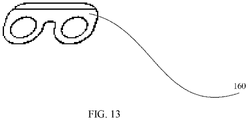
- FIG. 13 is a schematic diagram of the structure of a shielding portion in FIG. 4 .
- a shielding portion 160 is further disposed in the optical module 100, and the shielding portion 160 may have two holes, respectively passing through a 151 and a component 152.
- the shielding portion 160 may abut against an edge of a circuit board 140, to prevent signal interference.
- a support portion configured to support the transmit component 151 and the receive component 152 may be further disposed on the base 111.
- the support portion may have a support slot that matches a side surface of the transmit component 151 or the receive component 152, to improve stability of the transmit component 151 and the receive component 152.
Landscapes
- Physics & Mathematics (AREA)
- General Physics & Mathematics (AREA)
- Optics & Photonics (AREA)
- Optical Couplings Of Light Guides (AREA)
Applications Claiming Priority (1)
| Application Number | Priority Date | Filing Date | Title |
|---|---|---|---|
| PCT/CN2019/130743 WO2021134582A1 (zh) | 2019-12-31 | 2019-12-31 | 光模块解锁装置、光模块及光通信设备 |
Publications (3)
| Publication Number | Publication Date |
|---|---|
| EP4080257A1 true EP4080257A1 (de) | 2022-10-26 |
| EP4080257A4 EP4080257A4 (de) | 2022-12-21 |
| EP4080257B1 EP4080257B1 (de) | 2026-04-22 |
Family
ID=76685977
Family Applications (1)
| Application Number | Title | Priority Date | Filing Date |
|---|---|---|---|
| EP19958725.4A Active EP4080257B1 (de) | 2019-12-31 | 2019-12-31 | Entriegelungsvorrichtung für optische module, optisches modul und optische kommunikationsvorrichtung |
Country Status (4)
| Country | Link |
|---|---|
| US (1) | US12117655B2 (de) |
| EP (1) | EP4080257B1 (de) |
| CN (1) | CN114730052A (de) |
| WO (1) | WO2021134582A1 (de) |
Families Citing this family (6)
| Publication number | Priority date | Publication date | Assignee | Title |
|---|---|---|---|---|
| US11619789B2 (en) * | 2021-07-28 | 2023-04-04 | Quanta Computer Inc. | Dual connector carrier with simultaneous locking mechanism |
| US12045101B2 (en) * | 2021-09-16 | 2024-07-23 | Dell Products L.P. | Systems and methods for liquid immersion cooling of transceivers |
| TWI795057B (zh) * | 2021-11-02 | 2023-03-01 | 佳必琪國際股份有限公司 | 線纜連接器 |
| WO2024138616A1 (zh) * | 2022-12-30 | 2024-07-04 | 昂纳科技(深圳)集团股份有限公司 | 一种光模块及光收发连接组件 |
| CN116107045B (zh) * | 2023-04-12 | 2023-08-01 | 四川泰瑞创通讯技术股份有限公司 | 光模块 |
| CN120020623A (zh) * | 2023-11-17 | 2025-05-20 | 锐捷网络股份有限公司 | 一种光模块及通信设备 |
Family Cites Families (16)
| Publication number | Priority date | Publication date | Assignee | Title |
|---|---|---|---|---|
| CH700064A1 (de) * | 2008-12-01 | 2010-06-15 | Reichle & De Massari Fa | Duplex-adapter und sicherungsvorrichtung für eine optische steckverbindung. |
| CN202196205U (zh) * | 2011-09-14 | 2012-04-18 | 索尔思光电(成都)有限公司 | 一种万兆以太网接口小型可插拔光收发模块 |
| US9146366B2 (en) * | 2012-10-15 | 2015-09-29 | Finisar Corporation | Latch mechanism for communication module |
| CN105164560B (zh) * | 2013-03-05 | 2017-03-22 | 菲尼萨公司 | 用于通信模块的闩锁机构 |
| US9474188B2 (en) * | 2013-04-30 | 2016-10-18 | Lumentum Operations Llc | Sliding thermal contact for pluggable optic modules |
| CN204178013U (zh) * | 2014-10-11 | 2015-02-25 | 福州高意通讯有限公司 | 一种小型光电模块拉环式解锁复位装置 |
| US9983370B1 (en) * | 2016-05-24 | 2018-05-29 | Cisco Technology, Inc. | Passive heat sink for a small form factor pluggable |
| CN107907948B (zh) * | 2017-12-20 | 2024-05-03 | 武汉联特科技股份有限公司 | 光收发模块外壳及光收发模块 |
| CN110031943B (zh) * | 2018-01-11 | 2022-08-05 | 住友电工光电子器件创新株式会社 | 光收发器 |
| CN108873188A (zh) * | 2018-06-14 | 2018-11-23 | 宁波环球广电科技有限公司 | 光模块的退壳结构 |
| CN109143496A (zh) * | 2018-09-19 | 2019-01-04 | 索尔思光电(成都)有限公司 | 一种闩锁组件、解锁机构、光模块 |
| CN208689215U (zh) * | 2018-09-19 | 2019-04-02 | 宁波东立创芯光电科技有限公司 | 一种qsfp+光模块的解锁机构 |
| CN109541761B (zh) * | 2018-11-16 | 2020-10-09 | 武汉光迅科技股份有限公司 | 一种锁扣装置 |
| CN109683259B (zh) * | 2019-01-10 | 2021-05-11 | 武汉电信器件有限公司 | 一种可带纤插拔的光模块解锁结构 |
| CN109814212B (zh) * | 2019-01-31 | 2024-03-05 | 武汉联特科技股份有限公司 | Qsfp28到sfp28的端口并向下兼容qsfp+到sfp+端口转接设备及电路 |
| CN110286450A (zh) * | 2019-07-09 | 2019-09-27 | 深圳市亚派光电器件有限公司 | 光模块 |
-
2019
- 2019-12-31 EP EP19958725.4A patent/EP4080257B1/de active Active
- 2019-12-31 WO PCT/CN2019/130743 patent/WO2021134582A1/zh not_active Ceased
- 2019-12-31 CN CN201980102269.1A patent/CN114730052A/zh active Pending
-
2022
- 2022-06-27 US US17/850,360 patent/US12117655B2/en active Active
Also Published As
| Publication number | Publication date |
|---|---|
| CN114730052A (zh) | 2022-07-08 |
| EP4080257B1 (de) | 2026-04-22 |
| WO2021134582A1 (zh) | 2021-07-08 |
| US12117655B2 (en) | 2024-10-15 |
| EP4080257A4 (de) | 2022-12-21 |
| US20220357520A1 (en) | 2022-11-10 |
Similar Documents
| Publication | Publication Date | Title |
|---|---|---|
| US12117655B2 (en) | Optical module unlocking apparatus, optical module, and optical communication device | |
| CN110380285B (zh) | 顶部装载的电子连接系统 | |
| US9523826B2 (en) | Pluggable optical transceiver module | |
| KR0182255B1 (ko) | 래칭 기구를 구비한 커넥터 조립체 | |
| TWM468059U (zh) | 連接器模組 | |
| CN109856733A (zh) | 光收发器 | |
| US20090116185A1 (en) | Small form-factor pluggable transceiver module housing | |
| US20200088961A1 (en) | De-latching Mechanism and Optical Module Including the Same | |
| CN110417474A (zh) | 光收发器 | |
| CN111541074B (zh) | 一种电连接器组件 | |
| CN105207013B (zh) | 配置为减少电磁干扰泄漏的可插拔连接器和通信系统 | |
| JP7518491B2 (ja) | 光コネクタ機構および光コネクタ | |
| CN110031940B (zh) | 光模块的插拔装置 | |
| CN114236700A (zh) | 一种光模块 | |
| CN111541095B (zh) | 一种电连接器组件 | |
| CN212277447U (zh) | 一种电连接器组件 | |
| CN117031644A (zh) | 光模块 | |
| CN212647094U (zh) | 一种光模块 | |
| CN117420644A (zh) | 光模块 | |
| CN117008263A (zh) | 光模块 | |
| EP3514973B1 (de) | Steckbarer sende-empfänger mit kleinem formfaktor | |
| CN222636338U (zh) | 一种光模块 | |
| CN213091952U (zh) | 一种光模块 | |
| CN223742800U (zh) | 一种光模块 | |
| TWM504964U (zh) | 光纖連接器 |
Legal Events
| Date | Code | Title | Description |
|---|---|---|---|
| STAA | Information on the status of an ep patent application or granted ep patent |
Free format text: STATUS: THE INTERNATIONAL PUBLICATION HAS BEEN MADE |
|
| PUAI | Public reference made under article 153(3) epc to a published international application that has entered the european phase |
Free format text: ORIGINAL CODE: 0009012 |
|
| STAA | Information on the status of an ep patent application or granted ep patent |
Free format text: STATUS: REQUEST FOR EXAMINATION WAS MADE |
|
| 17P | Request for examination filed |
Effective date: 20220718 |
|
| AK | Designated contracting states |
Kind code of ref document: A1 Designated state(s): AL AT BE BG CH CY CZ DE DK EE ES FI FR GB GR HR HU IE IS IT LI LT LU LV MC MK MT NL NO PL PT RO RS SE SI SK SM TR |
|
| A4 | Supplementary search report drawn up and despatched |
Effective date: 20221122 |
|
| RIC1 | Information provided on ipc code assigned before grant |
Ipc: H04B 10/25 20130101ALI20221116BHEP Ipc: G02B 6/42 20060101AFI20221116BHEP |
|
| DAV | Request for validation of the european patent (deleted) | ||
| DAX | Request for extension of the european patent (deleted) | ||
| STAA | Information on the status of an ep patent application or granted ep patent |
Free format text: STATUS: EXAMINATION IS IN PROGRESS |
|
| 17Q | First examination report despatched |
Effective date: 20250127 |
|
| GRAP | Despatch of communication of intention to grant a patent |
Free format text: ORIGINAL CODE: EPIDOSNIGR1 |
|
| STAA | Information on the status of an ep patent application or granted ep patent |
Free format text: STATUS: GRANT OF PATENT IS INTENDED |
|
| INTG | Intention to grant announced |
Effective date: 20251209 |
|
| GRAS | Grant fee paid |
Free format text: ORIGINAL CODE: EPIDOSNIGR3 |
|
| GRAA | (expected) grant |
Free format text: ORIGINAL CODE: 0009210 |
|
| STAA | Information on the status of an ep patent application or granted ep patent |
Free format text: STATUS: THE PATENT HAS BEEN GRANTED |
|
| AK | Designated contracting states |
Kind code of ref document: B1 Designated state(s): AL AT BE BG CH CY CZ DE DK EE ES FI FR GB GR HR HU IE IS IT LI LT LU LV MC MK MT NL NO PL PT RO RS SE SI SK SM TR |
|
| REG | Reference to a national code |
Ref country code: CH Ref legal event code: F10 Free format text: ST27 STATUS EVENT CODE: U-0-0-F10-F00 (AS PROVIDED BY THE NATIONAL OFFICE) Effective date: 20260422 Ref country code: GB Ref legal event code: FG4D |