EP4080265B1 - Système de microscope et procédé correspondant - Google Patents
Système de microscope et procédé correspondant Download PDFInfo
- Publication number
- EP4080265B1 EP4080265B1 EP22168482.2A EP22168482A EP4080265B1 EP 4080265 B1 EP4080265 B1 EP 4080265B1 EP 22168482 A EP22168482 A EP 22168482A EP 4080265 B1 EP4080265 B1 EP 4080265B1
- Authority
- EP
- European Patent Office
- Prior art keywords
- sample stage
- microscope
- visual marker
- sample
- optical imaging
- Prior art date
- Legal status (The legal status is an assumption and is not a legal conclusion. Google has not performed a legal analysis and makes no representation as to the accuracy of the status listed.)
- Active
Links
Images

Classifications
-
- G—PHYSICS
- G02—OPTICS
- G02B—OPTICAL ELEMENTS, SYSTEMS OR APPARATUS
- G02B21/00—Microscopes
- G02B21/0004—Microscopes specially adapted for specific applications
- G02B21/002—Scanning microscopes
- G02B21/0024—Confocal scanning microscopes (CSOMs) or confocal "macroscopes"; Accessories which are not restricted to use with CSOMs, e.g. sample holders
- G02B21/008—Details of detection or image processing, including general computer control
-
- G—PHYSICS
- G02—OPTICS
- G02B—OPTICAL ELEMENTS, SYSTEMS OR APPARATUS
- G02B21/00—Microscopes
- G02B21/06—Means for illuminating specimens
-
- G—PHYSICS
- G02—OPTICS
- G02B—OPTICAL ELEMENTS, SYSTEMS OR APPARATUS
- G02B21/00—Microscopes
- G02B21/24—Base structure
- G02B21/26—Stages; Adjusting means therefor
-
- G—PHYSICS
- G02—OPTICS
- G02B—OPTICAL ELEMENTS, SYSTEMS OR APPARATUS
- G02B21/00—Microscopes
- G02B21/36—Microscopes arranged for photographic purposes or projection purposes or digital imaging or video purposes including associated control and data processing arrangements
-
- G—PHYSICS
- G02—OPTICS
- G02B—OPTICAL ELEMENTS, SYSTEMS OR APPARATUS
- G02B21/00—Microscopes
- G02B21/36—Microscopes arranged for photographic purposes or projection purposes or digital imaging or video purposes including associated control and data processing arrangements
- G02B21/365—Control or image processing arrangements for digital or video microscopes
Definitions
- Examples relate to a microscope system and to a corresponding control method and more specifically, but not exclusively, to a concept for determining a position of a movable sample stage of the microscope system.
- Microscopes for industrial applications often have movable sample stages that can be moved along two axes (further denoted X- and Y-axis). To perform imaging across various positions of the sample stage, precise X-Y positioning of the stage may be required for object alignment and image stitching. In many cases, optical or magnetic linear encoders are used to determine the X-Y positions of the stage. Image stitching may use both the measured X-Y positions as well as image landmarks (of the sample) to align and collate the images.
- linear encoders may have different thermal expansion coefficients than the sample stage, making the positional readout inaccurate.
- the stage may have to stop in order to capture an image at each desired X-Y position. Image stitching can be difficult or inaccurate when X-Y positions are inaccurate, and when the object has weak visual contrast or repetitive patterns.
- Publication EP 2 402 813 A2 titled “Microscope and Area Determination Method,” describes a microscope that has dark field illumination and bright field illumination. The different types of illumination are used to shine light on a sample mounted on a slide glass that is covered with a cover glass and mounting agent. An image capturing unit is also included, which takes a dark field image of the sample illuminated by the dark field illumination and a bright field image of the sample illuminated by the bright field illumination. The microscope also has a magnified portion image acquisition area determination unit that uses the dark and bright field images to detect the edge of the cover glass that covers the sample. The internal area of the detected edge of the cover glass is then determined as the magnified portion image acquisition area of the sample.
- Publication US 2018/088306 A1 titled "Observation Method and Specimen Observation Apparatus” describes a method for observing specimens. The method involves taking an image of the specimen with specific markers in the first specimen stage, obtaining the pixel coordinates of the markers, acquiring the stage coordinates of the markers on the second specimen stage, and converting the pixel coordinates of the image into stage coordinates to move the second specimen stage.
- Publication JP H09 36024 A with the title "Scan Type Aligner and Device Manufacturing Method using the same” discusses an approach for enabling the alignment of a mask to a wafer without any reference mask. This is achieved by placing a wafer reference plate on a mask stage and detecting its position on a wafer stage. The same is done for the wafer, which is placed on a wafer stage.
- Publication US 6 384 898 B1 discusses a projection exposure apparatus that uses an alignment illumination system with a flash lamp to direct light onto an alignment mark on a wafer through a microscope optical system.
- a visual approach may be chosen, with a visual marker that is displayed underneath the sample stage.
- the rates of thermal expansion may be the same, or at least similar, for the sample stage and the visual marker.
- An optical imaging sensor is used to generate image data of an image showing the visual marker, and the image data is analyzed to determine the position of the sample stage.
- the sample stage is configured to move along two lateral dimensions.
- the control system may be configured to determine the position of the sample stage with respect to the two lateral dimensions. In other words, the X-Y-position of the sample stage may be determined.
- the sample stage may be a motorized sample stage.
- a motorized sample stage may be used for automatic recording of large samples across multiple positions of the sample stage.
- a throughput of the imaging of the microscope may be increased by continuously keeping the sample stage moving.
- the sample stage may move continuously, and the proposed concept may be used to determine the position of the sample stage as the sample stage moves.
- the motorized sample stage may be configured to continuously move while the microscope is generating a plurality of images at a plurality of points in time.
- the optical imaging sensor may be configured to generate the image data of the image showing the visual marker while the motorized sample stage is in motion.
- the control system may be configured to determine the position of the motorized sample stage at the plurality of points in time based on the image data of images showing the visual marker being generated while the motorized sample stage is in motion. This may increase the throughput of the microscope system.
- a strobe light may be used.
- the microscope system may comprise at least one illumination element for illuminating the visual marker and/or the sample with light strobes.
- the control system may be configured to trigger the illumination element to emit light strobes at the plurality of points in time.
- the light strobes may be brighter than environmental light, so that most of the light being recorded by an optical imaging sensor of the microscope and/or by the optical imaging sensor used for determining the position of the sample stage is caused by the light strobes.
- control system may be configured to trigger the illumination element to emit the light strobes so that each pixel of an image being generated by the microscope and/or each pixel of a sample of the image data of the image showing the visual marker is exposed to a reflection of the same light strobe.
- the light strobes may be timed so that, as the respective optical imaging sensor is read out line-by-line or block-by-block, all of the lines/blocks of the optical imaging sensor being used to generate an image frame have been exposed to light from the same strobe.
- the visual marker is arranged at a bottom side of the sample stage and the optical imaging sensor is arranged below the sample stage. This way, the visual marker might not be covered by a large sample, and the microscope can be handled without interfering with the optical imaging sensor, e.g., when the microscope is tilted.
- the microscope system comprises two or more optical imaging sensors for providing image data of two or more images showing at least one of two or more visual markers of the sample stage.
- the control system may be configured to determine the position of the sample stage based on the image data of the two or more images showing the at least one of the two or more visual markers.
- a lateral extent of the visual marker may be at least as large as a maximal lateral movement of the sample stage.
- the size of the visual marker may enable the determination of the position of the sample stage.
- the visual marker has a two-dimensional visual pattern.
- the two-dimensional pattern may be used to determine the position of the sample stage in two lateral dimensions.
- the sample stage may comprise a first visual marker being aligned with a first lateral direction of movement and a second visual marker being aligned with a second lateral direction of movement of the sample stage.
- Each of the first and second marker may have a one-dimensional visual pattern.
- the first visual marker may be used to determine the position of the sample stage along the first lateral direction of movement
- the second visual marker may be used to determine the position of the sample stage along the second lateral direction of movement.
- control system may be configured to determine the position of the sample stage relative to the microscope. This way, the position of the sample stage, and thus the position of the sample being recorded, may be recorded with the images taken by the microscope.
- control system may be configured to annotate the images taken by the microscope with the position of the sample stage at the time the images are generated.
- control system of the microscope system comprises one or more processors and one or more storage devices.
- the control system is configured to obtain the image data of an image showing the visual marker of the sample stage from the optical imaging sensor of the microscope system.
- the system is configured to determine the position of the sample stage based on the image data of the image showing the visual marker.
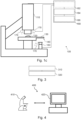
- Fig. 1a shows a schematic diagram of an example of a microscope system 100.
- the microscope system 100 comprises a microscope 110 configured to generate images of a sample 120 being arranged on a sample stage.
- a microscope is an optical instrument that is suitable for examining objects that are too small to be examined by the human eye (alone).
- a microscope may provide an optical magnification of a sample, such as the sample 120.
- the optical magnification is often provided for a camera or an imaging sensor, such as an optical imaging sensor of the microscope 110.
- the microscope 110 may further comprise one or more optical magnification components that are used to magnify a view on the sample, such as an objective (i.e., lens).
- the sample being viewed through the microscope may be a sample of organic tissue, e.g., arranged within a petri dish or present in a part of a body of a patient.
- the microscope system 100 may be a microscope system for use in a laboratory, e.g., a microscope that may be used to examine the sample of organic tissue in a petri dish.
- the microscope system 100 may be a microscope system for use in material science and/or quality control.
- the microscope system 100 may be a microscope system for generating highly detailed images of a large sample by generating and stitching together a plurality of images.
- the microscope 110 of the microscope system 110 is used with a number of additional optional or mandatory components. Therefore, the term “microscope system” is used, in order to also cover the portions of the system that are not part of the actual microscope (which comprises optical components and is thus also denoted “optics carrier”), but which are used in conjunction with the microscope, such as a sample stage, an additional optical imaging sensor, and a control system, as will be shown in the following.
- the microscope system further comprises a sample stage (e.g., an X-Y-stage) 130 configured to carry the sample.
- the sample stage comprises a visual marker 140 (that is arranged at a pattern area of the sample stage).
- the microscope system further comprises an optical imaging sensor (also denoted X-Y camera) 150 configured to provide image data of an image showing the visual marker of the sample stage.
- the microscope system further comprises a control system configured to determine a position of the sample stage based on the image data of the image showing the visual marker.
- Fig. 1b shows a block diagram of an example of the control system 160 for a microscope system, e.g. for the microscope system of Fig. 1a .
- the control system 160 comprises one or more processors 164 and one or more storage devices 166.
- the control system comprises one or more interfaces 162.
- the one or more processors are coupled to the one or more storage devices and to the optional interface.
- control system 160 is configured to obtain the image data of the image showing the visual marker of the sample stage from the optical imaging sensor 150 of the microscope system (e.g. via the interface 162).
- control system is configured to determine the position of the sample stage based on the image data of the image showing the visual marker.
- Fig. 1c a schematic diagram is shown of an example of the microscope system 100 comprising the control system 160.
- the microscope system 100 of Fig. 1c shows further optional components, such as at least one illumination element 170.
- Various examples of the present disclosure provide a concept for detecting a position of a sample stage of a microscope, to support image stitching of images generated by the microscope.
- the proposed microscope system is equipped with the sample stage 130, of which the position is determined by the control system. Accordingly, the sample stage may move (and is thus movable) relative to the microscope 110. Furthermore, the sample stage may move relative to optical imaging sensor 150. In other words, the optical imaging sensor may remain at a fixed position, while the sample stage moves relative to the optical imaging sensor. In effect, the position of the microscope 110 and of the optical imaging sensor 150 may shift relative to the sample stage 130 if the sample stage is moved.
- the sample stage may be moved by hand.
- the sample stage may be a motorized sample stage. In other words, the sample stage may comprise a motor for moving the sample stage.
- the sample stage may be configured to move relative to the microscope according to a pre-defined pattern, e.g., according to a z-shaped pattern or according to a serpentine pattern.
- the sample stage may be moved along one or two lateral dimensions relative to the microscope 110.
- the sample stage may be configured to move along two lateral dimensions (with one of the lateral dimensions being perpendicular to the other lateral dimension). Therefore, the sample stage may also be denoted a X-Y-stage, as it may be moved along the X- and Y- lateral dimensions.
- the sample stage may be further movable along a third dimension (i.e. the vertical dimension or Z-dimension).
- a lateral (i.e. horizontal) dimension is defined perpendicular to a direction of the force of gravity
- a vertical dimension is defined in parallel to the force of gravity.
- the sample stage comprises the visual marker 140, which is used to determine the position of the sample stage.
- the visual marker may be printed on the sample stage, or the visual marker may be etched into the sample stage, e.g., using a laser-based etching method.
- the visual marker may be inherent to the material of the sample stage, e.g., a result of a cast or tool being used to manufacture the sample stage.
- the visual marker may be attached to the sample stage using an adhesive or using another mechanical means for fastening the visual marker to the sample stage, e.g. using screws or rivets.
- the visual marker may be designed such, that specular reflections are reduced or minimized.
- the visual marker 140 is arranged at (e.g. printed onto, etched into or attached to) a bottom side of the sample stage and the optical imaging sensor is arranged (vertically) below the sample stage.
- the visual marker may be arranged at (e.g. printed onto, etched into or attached to) a top side of the sample stage and the optical imaging sensor may be arranged above the sample stage (not shown).
- the mentioned alternative regarding a marker on the top side of the stage is not covered by the appended claims.
- the term "top side” of the sample stage may be a side of the sample stage that faces away from the center of gravity of the earth, while the “bottom side” of the sample stage may be a side of the sample stage that faces towards the center of gravity of the earth.
- the optical imaging sensor being arranged above the sample stage means that the optical imaging sensor is located further away from the center of gravity of the earth than the sample stage, or at least further away than a surface of the sample stage comprising the visual marker.
- the optical imaging sensor being arranged below the sample stage means that the optical imaging sensor is located closer to the center of gravity of the earth than the sample stage, or at least closer than a surface of the sample stage comprising the visual marker.
- the position of the sample stage is determined by generating and analyzing image data of the visual marker of the sample stage.
- the visual marker moves with the sample stage.
- a portion of the visual marker that is visible in the image showing the visual marker also changes as the sample stage moves, as the sample stage also moves relative to the optical imaging sensor.
- the visual marker moves as well, and the movement of the visual marker is shown in the image showing the visual marker.
- a portion of the visual marker may be shown in the image of the image data generated by the optical imaging sensor at any (lateral) position of the sample stage. Consequently, a lateral extent (e.g. a maximal lateral distance along the one or two lateral dimensions between two outermost portions of the visual marker) of the visual marker may be at least as large as a maximal lateral movement of the sample stage. In other words, the visual marker may be large enough, so that, at any lateral position of the sample stage, a portion of the visual marker may be shown in the image of the image data generated by the optical imaging sensor.
- the sample stage may comprise two or more visual markers, which may be recorded by two or more optical imaging sensors.
- the microscope system may comprise two or more optical imaging sensors for providing image data of two or more images showing at least one of the two or more visual markers of the sample stage.
- a single optical imaging sensor may be used to provide image data of an image showing two or more visual markers of the sample stage, or two or more optical imaging sensors may be used to provide image data of an image showing a single contiguous visual marker.
- the visual marker may use any visual pattern that provides sufficient contrast for the subsequent analysis.
- the visual marker may comprise a (pseudo-)random pattern, e.g. a random pattern that is based on dots, rectangles, triangles, polygons etc.
- the visual marker may be the inherent texture of the material surface.
- a two-dimensional visual pattern may be used, so the movement along two lateral dimensions can be reliably tracked.
- the visual marker may have a two-dimensional visual pattern.
- two visual markers each having a one-dimensional visual pattern, such as a barcode may be used.
- the sample stage may comprise a first visual marker being aligned with a first lateral direction of movement and a second visual marker being aligned with a second lateral direction of movement of the sample stage, with each of the first and second marker having a one-dimensional (or even two-dimensional) visual pattern. Specular reflection due to the pattern may be reduced or minimized so that a motion of the sample stage, and thus the visual marker, can be visually tracked.
- the optical imaging sensor 150 is employed by the control system to generate image data of the visual marker, which the control system in turn evaluates to determine the position of the sample stage. Accordingly, the optical imaging sensor 150 is configured to generate the image data.
- the optical imaging sensor 150 and/or the optical imaging sensor of the microscope 110 may comprise or be an APS (Active Pixel Sensor) - or a CCD (Charge-Coupled-Device)-based imaging sensor.
- APS-based imaging sensors light is recorded at each pixel using a photo-detector and an active amplifier of the pixel.
- APS-based imaging sensors are often based on CMOS (Complementary Metal-Oxide-Semiconductor) or S-CMOS (Scientific CMOS) technology.
- CCD-based imaging sensors incoming photons are converted into electron charges at a semiconductor-oxide interface, which are subsequently moved between capacitive bins in the imaging sensors by a control circuitry of the imaging sensors to perform the imaging.
- the system 160 is configured to obtain (i.e., receive or read out) the image data from the optical imaging sensor.
- the system 160 may be configured to obtain further image data from the optical imaging sensor of the microscope 110.
- the image data may be obtained by receiving the image data from the respective optical imaging sensor (e.g., via the interface 162), by reading the image data out from a memory of the respective optical imaging sensor (e.g., via the interface 162), or by reading the image data from a storage device 166 of the control system 160, e.g., after the image data has been written to the storage device 166 by the respective optical imaging sensor or by another system or processor.
- the image data of the optical imaging sensor 150 comprises an image showing the visual marker of the sample stage. Accordingly, the optical imaging sensor 150 may be directed towards the visual marker of the sample stage, i.e. towards the sample stage. As the visual marker is moved above or underneath the optical imaging sensor (together with the sample stage), the movement of the visual marker is represented by the image data.
- the image data comprises an image showing the visual marker, e.g., a portion of the visual marker, according to a current position of the sample stage. For example, at each position the sample stage, a unique portion of the visual marker may be shown by the image included in the image data.
- the position of the sample stage may be tracked over a plurality of points in time.
- the sample stage may be moved continuously, with an image of the sample being generated by the microscope (or rather an optical imaging sensor of the microscope) at the plurality of points in time.
- the images of the sample and of the visual marker may be taken while the sample stage is moving.
- the image data may comprise a plurality of images showing the visual marker (or rather a plurality of portions of the visual marker) representing the position of the sample stage at the plurality of points in time.
- the sample stage may move continuously, with exceptions being made for changes in direction of the movement. However, even with such discontinuities in the movement, the movement of the sample stage may be considered to be continuous.
- the control system is subsequently used to analyze the image data and determine the position of the sample stage.
- the position of the sample may be defined with respect to the one or two lateral dimensions.
- the control system may be configured to determine the position of the sample stage with respect to the one or two lateral dimensions.
- the control system may be configured to determine the position of the sample stage with respect to a one- or two-dimensional coordinate system representing the one or two lateral dimensions. For example, for each of the one or two dimensions, the position of the sample stage may be determined by the control system.
- the position of the sample stage may be determined relative to the microscope.
- the control system is configured to determine the position of the sample stage relative to the microscope.
- the microscope may have a fixed position within the one- or two-dimensional coordinate system, and thus the position of the sample stage with respect to the one- or two-dimensional coordinate system may also be defined relative to the microscope.
- the pattern shown in the image showing the visual marker may be analyzed to determine the position of the sample stage.
- the image may show a portion of the visual marker, with each portion having a unique pattern.
- the control system may be configured to compare the portion of the visual marker shown in the image to the (entire) pattern of the visual marker, to determine the position of the portion within the visual marker, and to determine the position of the sample stage based on the position of the portion within the visual marker.
- the position of the sample stage may be encoded within the pattern of the visual marker.
- the visual marker may comprise a plurality of position indicators that are encoded within the pattern of the visual marker, with the plurality of position indicators being embedded at a plurality of pre-defined positions of the visual marker.
- the control system may be configured to decode one or more position indicators shown in the image to determine the position of the sample stage based on the decoded position indicators. For example, if one or more position indicators are shown in the image, the position of the one or more position indicators within the image may be used to determine the position of the sample stage.
- two or more optical imaging sensors may be used in combination with two or more visual markers that are arranged at different positions of the sample stage.
- the same approach may be used, depending on which of the two or more visual markers is visible at a given time.
- the control system may be configured to determine the position of the sample stage based on the image data of the two or more images showing the at least one of the two or more visual markers. At any given time, at least one of the two or more visual markers may be shown in at least one of the two or more images. Therefore, the control system may be configured to determine the position of the sample stage based on the at least one of the two or more visual markers that is shown in at least one of the two or more images.
- the microscope system that is introduced in connection with Figs. 1a to 1c may be used as a microscope for generating a (highly-detailed) composite image of the sample by subsequently generating a plurality of (partially overlapping) images of the sample using the optical imaging sensor of the microscope, and stitching together the plurality of images to generate the composite image.
- the X-Y camera i.e. the optical imaging sensor 150
- the microscope's main camera i.e. the optical imaging sensor of the microscope
- their respective (strobing) light sources it is possible to capture photos with accurate XY positional information while the stage is moving.
- the sample stage may be used to move the sample relative to the microscope as the images are taken.
- this process may take a long time, as the sample stage moves in-between positions, stops, an image is taken, a position at which the image is taken is determined, and then the next position is taken. In various examples of the present disclosure, this process may be sped up using the proposed concept.
- the movement of the sample stage may be continuous, instead of stopping the sample stage for every image taken by the optical imaging sensor of the microscope.
- the motorized sample stage may be configured to continuously move while the microscope is generating a plurality of images at a plurality of points in time, e.g., without stopping the sample stage for the purpose of exposing the optical imaging sensor of the microscope while the sample is in a fixed position relative to the microscope.
- the optical imaging sensor 150 may be configured to generate the image data of the image showing the visual marker while the motorized sample stage is in motion.
- an image, or rather a plurality of images to be stitched together to form the composite image of the sample may be generated by the optical imaging sensor of the microscope at the plurality of points in time, and corresponding images may be generated, at the plurality of points in time, by the optical imaging sensor that is used to determine the position of the sample stage.
- the control system may be configured to determine the position of the motorized sample stage at the plurality of points in time based on the image data of images showing the visual marker being generated while the motorized sample stage is in motion. For example, at each of the plurality of points in time, an image may be generated by the optical imaging sensor of the microscope and by the optical imaging sensor being used to determine the position of the sample stage. The position of the sample stage at the plurality of points in time may be determined based on the images taken by the optical imaging sensor 150 at the plurality of points in time.
- optical imaging sensors may comprise a two-dimensional grid of pixels, comprising a plurality of lines of pixels and a plurality of columns of pixels. The content of the two-dimensional grid of pixels is read out to generate a frame of image data. In many cases, only a subset of pixels of the two-dimensional grid of pixels is read out at once, e.g. line-by-line or block-by-block.
- the duration of exposure to light of the pixels may be (substantially) the same for all of the pixels. As some pixels are read out earlier than others, these pixels are also exposed to the light earlier, to maintain the same exposure duration. The later a pixel is read out, the later the exposure of the pixel begins. The concept is shown in connection with Fig. 2 .
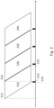
- Fig. 2 shows an example of a timing diagram of a strobe-light relative to a read-out of an optical imaging sensor.
- a strobe-light timing is synchronized to an optical imaging sensor exposure timing.
- the x-axis shows the time.
- Four frames are shown, a first frame 210, a second frame 220, a third frame 230 and a fourth frame 240.
- the exposure of the lines of pixels to light, and subsequent read-out of the lines of pixels are time-shifted.
- Fig. 2a shows a line 211 indicating the beginning of exposure of the first line, and a further line 212 indicating the beginning of exposure of the last line of the first frame 210.
- FIG. 2a further shows a line 214 indicating the end of exposure of the first line and a line 215 indicating the end of exposure of the last line.
- the end of exposure of the last line of the first frame 210 may overlap with the beginning of exposure of the first line (or rather most lines) of the second frame 220.
- there is a time interval (between the beginning 212 of exposure of the last line and the end 214 of exposure of the first line), where all of the pixels of the optical imaging sensor are exposed to the same light.
- a strobe light 213 may be used at this moment to illuminate the sample (and/or the visual marker), so that the light being recorded by the optical imaging sensor is predominately based on the reflections of the strobe light, thus drowning out the light recorded apart from the reflections of the strobe.
- the optical imaging sensor being used to determine the position of the sample stage and/or the optical imaging sensor of the microscope may have a synchronized strobing light 170 mounted next to or around its lens (as shown in Fig. 1c ).
- the microscope's main optical imaging sensor and light source may also be synchronized with the optical imaging sensor and light source being used to determine the position of the sample stage to allow continuous capturing while the XY stage is in motion.
- the microscope system may comprise at least one illumination element 170 for illuminating the visual marker and/or the sample with light strobes.
- the control system may be configured to trigger the illumination element to emit light strobes at the plurality of points in time, e.g. before a first line of the grid of pixels has stopped exposing and after a last line of the grid of pixels has started exposing during the generation of the frame.
- the control system may be configured to trigger the illumination element to emit the light strobes so that each pixel of an image being generated by the microscope and/or each pixel of a sample of the image data of the image showing the visual marker is exposed to a reflection of the same light strobe, e.g. before a first line of the grid of pixels has stopped exposing and after a last line of the grid of pixels has started exposing during the generation of the frame if the sensor is exposed read out line-by-line.
- the light/illumination element may emit a short but strong burst of light after the respective optical imaging sensor's last line has started exposing but before the first line has stopped exposing.
- a strobing light source can be used to eliminate image skew when the stage is moving.
- the maximal speed of the stage may be capped by the field of view and frame rate of this camera, so that it can have enough overlapping image content between adjacent frames to calculate motion.
- the position of the sample stage is used for stitching the images generated by the optical imaging sensor of the microscope together to generate the composite image.
- information on the position of the sample stage e.g. at the plurality of points in time, may be stored in a storage device 166 of the control system, or be provided to an external entity.
- the information on the position of the sample stage may be stored with the images generated by the optical imaging sensor for the microscope.
- the control system may be configured to annotate the images taken by the microscope with the position of the sample stage at the time the images are generated.
- control system may be configured to obtain further image data comprising the images taken by the optical imaging sensor of the microscope from the optical imaging sensor of the microscope system, and to annotate the images taken by the optical imaging sensor with the information on the position, e.g. by generating, for each image taken, a corresponding data unit, e.g., a file, representing the position of the sample stage, and storing or outputting the data representing the position together with the file of the image taken.
- the information on the position may be included in metadata of the respective image taken by the optical imaging sensor of the microscope.
- a patch of patterns i.e. a visual marker
- the patch of patterns may preferably exhibit similar properties with respect to thermal expansion as the sample stage itself.
- the dimensions of the visual marker may be at least as large as the range of X-Y movements of the stage.
- multiple patches of pattern coupled with the same number of cameras can be distributed across different areas of the stage to reduce the stage size.
- the pattern can be random dots or even the inherent texture of the material surface. Specular reflection may be reduced so that motion can be visually tracked.
- a digital camera e.g., the optical imaging sensor being used for determining the position of the sample stage, is aimed at the pattern and used to determine the position of the sample stage.
- the digital camera sends image data (e.g., a video) to a processor to analyze and track the movement of the stage. Because the pattern is on the stage itself, its movement accurately represents the movement of the sample stage and hence the (X-Y) position of the sample stage.
- the one or more interfaces 112 may correspond to one or more inputs and/or outputs for receiving and/or transmitting information, which may be in digital (bit) values according to a specified code, within a module, between modules or between modules of different entities.
- the one or more interfaces 112 may comprise interface circuitry configured to receive and/or transmit information.
- the one or more processors 114 may be implemented using one or more processing units, one or more processing devices, any means for processing, such as a processor, a computer or a programmable hardware component being operable with accordingly adapted software.
- the described function of the one or more processors 114 may as well be implemented in software, which is then executed on one or more programmable hardware components.
- Such hardware components may comprise a general-purpose processor, a Digital Signal Processor (DSP), a micro-controller, etc.
- the one or more storage devices 116 may comprise at least one element of the group of a computer readable storage medium, such as a magnetic or optical storage medium, e.g., a hard disk drive, a flash memory, a Solid-State Drive (SSD), Floppy-Disk, Random Access Memory (RAM), Programmable Read Only Memory (PROM), Erasable Programmable Read Only Memory (EPROM), an Electronically Erasable Programmable Read Only Memory (EEPROM), or a network storage.
- a computer readable storage medium such as a magnetic or optical storage medium, such as a magnetic or optical storage medium, e.g., a hard disk drive, a flash memory, a Solid-State Drive (SSD), Floppy-Disk, Random Access Memory (RAM), Programmable Read Only Memory (PROM), Erasable Programmable Read Only Memory (EPROM), an Electronically Erasable Programmable Read
- the microscope system and/or the control system may comprise one or more additional optional features corresponding to one or more aspects of the proposed concept or one or more examples described above or below.
- Fig. 3 shows a flow chart of an example of a corresponding method for a microscope system, e.g. the microscope system 100 of Figs. 1a to 1c .
- the microscope system comprises a microscope 110 configured to generate an image of a sample 120 being arranged on a sample stage and a sample stage 130 configured to carry the sample 120, the sample stage comprising a visual marker 140.
- the method comprises obtaining 310 image data of an image showing the visual marker of the sample stage.
- the method comprises determining 320 a position of the sample stage based on the image data of the image showing the visual marker.
- aspects have been described in the context of an apparatus, it is clear that these aspects also represent a description of the corresponding method, where a block or device corresponds to a method step or a feature of a method step. Analogously, aspects described in the context of a method step also represent a description of a corresponding block or item or feature of a corresponding apparatus.
- a microscope comprising a system as described in connection with one or more of the Figs. 1a to 3 .
- a microscope may be part of or connected to a system as described in connection with one or more of the Figs. 1a to 3 .
- Fig. 4 shows a schematic illustration of a system 400 configured to perform a method described herein.
- the system 400 comprises a microscope 410 and a computer system 420.
- the microscope 410 is configured to take images and is connected to the computer system 420.
- the computer system 420 is configured to execute at least a part of a method described herein.
- the computer system 420 may be configured to execute a machine learning algorithm.
- the computer system 420 and microscope 410 may be separate entities but can also be integrated together in one common housing.
- the computer system 420 may be part of a central processing system of the microscope 410 and/or the computer system 420 may be part of a subcomponent of the microscope 410, such as a sensor, an actor, a camera or an illumination unit, etc. of the microscope 410.
- the computer system 420 may be a local computer device (e.g. personal computer, laptop, tablet computer or mobile phone) with one or more processors and one or more storage devices or may be a distributed computer system (e.g. a cloud computing system with one or more processors and one or more storage devices distributed at various locations, for example, at a local client and/or one or more remote server farms and/or data centers).
- the computer system 420 may comprise any circuit or combination of circuits.
- the computer system 420 may include one or more processors which can be of any type.
- processor may mean any type of computational circuit, such as but not limited to a microprocessor, a microcontroller, a complex instruction set computing (CISC) microprocessor, a reduced instruction set computing (RISC) microprocessor, a very long instruction word (VLIW) microprocessor, a graphics processor, a digital signal processor (DSP), multiple core processor, a field programmable gate array (FPGA), for example, of a microscope or a microscope component (e.g. camera) or any other type of processor or processing circuit.
- CISC complex instruction set computing
- RISC reduced instruction set computing
- VLIW very long instruction word
- DSP digital signal processor
- FPGA field programmable gate array
- circuits may be included in the computer system 420 may be a custom circuit, an application-specific integrated circuit (ASlC), or the like, such as, for example, one or more circuits (such as a communication circuit) for use in wireless devices like mobile telephones, tablet computers, laptop computers, two-way radios, and similar electronic systems.
- the computer system 420 may include one or more storage devices, which may include one or more memory elements suitable to the particular application, such as a main memory in the form of random access memory (RAM), one or more hard drives, and/or one or more drives that handle removable media such as compact disks (CD), flash memory cards, digital video disk (DVD), and the like.
- RAM random access memory
- CD compact disks
- DVD digital video disk
- the computer system 420 may also include a display device, one or more speakers, and a keyboard and/or controller, which can include a mouse, trackball, touch screen, voice-recognition device, or any other device that permits a system user to input information into and receive information from the computer system 420.
- Some or all of the method steps may be executed by (or using) a hardware apparatus, like for example, a processor, a microprocessor, a programmable computer or an electronic circuit. In some embodiments, some one or more of the most important method steps may be executed by such an apparatus.
- embodiments of the invention can be implemented in hardware or in software.
- the implementation can be performed using a non-transitory storage medium such as a digital storage medium, for example a floppy disc, a Hard-Disk Drive (HDD), a Solid-State Drive (SSD), a DVD, a Blu-Ray, a CD, a ROM, a PROM, and EPROM, an EEPROM or a FLASH memory, having electronically readable control signals stored thereon, which cooperate (or are capable of cooperating) with a programmable computer system such that the respective method is performed. Therefore, the digital storage medium may be computer readable.
- a digital storage medium for example a floppy disc, a Hard-Disk Drive (HDD), a Solid-State Drive (SSD), a DVD, a Blu-Ray, a CD, a ROM, a PROM, and EPROM, an EEPROM or a FLASH memory, having electronically readable control signals stored thereon, which cooperate (or are capable of cooperating)
- Some embodiments according to the invention comprise a data carrier having electronically readable control signals, which are capable of cooperating with a programmable computer system, such that one of the methods described herein is performed.
- examples can be implemented as a computer program product with a program code, the program code being operative for performing one of the methods when the computer program product runs on a computer.
- the program code may, for example, be stored on a machine readable carrier.
- a further example, not covered by the claims, is, therefore, a storage medium (or a data carrier, or a computer-readable medium) comprising, stored thereon, the computer program for performing one of the methods described herein when it is performed by a processor.
- the data carrier, the digital storage medium or the recorded medium are typically tangible and/or non-transitionary.
- a further example, not covered by the claims, is an apparatus as described herein comprising a processor and the storage medium.
- a further example, not covered by the claims, is, therefore, a data stream or a sequence of signals representing the computer program for performing one of the methods described herein.
- the data stream or the sequence of signals may, for example, be configured to be transferred via a data communication connection, for example, via the internet.
- a further example, not covered by the claims, comprises a processing means, for example, a computer or a programmable logic device, configured to, or adapted to, perform one of the methods described herein.
- a processing means for example, a computer or a programmable logic device, configured to, or adapted to, perform one of the methods described herein.
- An example not covered by the claims, comprises a computer having installed thereon the computer program for performing one of the methods described herein.
- a further example, not covered by the claims, comprises an apparatus or a system configured to transfer (for example, electronically or optically) a computer program for performing one of the methods described herein to a receiver.
- the receiver may, for example, be a computer, a mobile device, a memory device or the like.
- the apparatus or system may, for example, comprise a file server for transferring the computer program to the receiver.
- a programmable logic device for example, a field programmable gate array
- a field programmable gate array may cooperate with a microprocessor in order to perform one of the methods described herein.
- the methods are preferably performed by any hardware apparatus.
Landscapes
- Physics & Mathematics (AREA)
- Chemical & Material Sciences (AREA)
- Analytical Chemistry (AREA)
- General Physics & Mathematics (AREA)
- Optics & Photonics (AREA)
- Engineering & Computer Science (AREA)
- Multimedia (AREA)
- Computer Vision & Pattern Recognition (AREA)
- General Engineering & Computer Science (AREA)
- Microscoopes, Condenser (AREA)
Claims (13)
- Système de microscope (100 ; 400) comprenant :un microscope (110; 410) configuré pour générer des images d'un échantillon (120) disposé sur une platine d'échantillon ;une platine (130) d'échantillon configurée pour porter l'échantillon, la platine d'échantillon comprenant un marqueur visuel (140) ;un capteur (150) d'imagerie optique configuré pour fournir des données d'image d'une image montrant le marqueur visuel de la platine d'échantillon ; etdans lequel le marqueur visuel est disposé au niveau d'un côté inférieur de la platine d'échantillon et le capteur d'imagerie optique est disposé au-dessous de la platine d'échantillon,un système de commande (160 ; 420) configuré pour déterminer une position de la platine d'échantillon sur la base des données d'image de l'image montrant le marqueur visuel.
- Système de microscope selon la revendication 1, dans lequel la platine d'échantillon est configurée pour se déplacer le long de deux dimensions latérales, dans lequel le système de commande est configuré pour déterminer la position de la platine d'échantillon par rapport aux deux dimensions latérales, et/ou dans lequel la platine d'échantillon est une platine d'échantillon motorisée.
- Système de microscope selon la revendication 2, dans lequel la platine d'échantillon motorisée est configurée pour se déplacer en continu pendant que le microscope génère une pluralité d'images à une pluralité d'instants, le capteur d'imagerie optique étant configuré pour générer les données d'image de l'image montrant le marqueur visuel pendant que la platine d'échantillon motorisée est en mouvement, dans lequel le système de commande est configuré pour déterminer la position de la platine d'échantillon motorisée à la pluralité d'instants sur la base des données d'image d'images montrant le marqueur visuel généré pendant que la platine d'échantillon motorisée est en mouvement.
- Système de microscope selon la revendication 3, dans lequel le système de microscope comprend au moins un élément (170) d'éclairage pour éclairer le marqueur visuel et/ou l'échantillon avec des impulsions lumineuses, dans lequel le système de commande est configuré pour déclencher l'élément d'éclairage pour émettre des impulsions lumineuses à la pluralité d'instants.
- Système de microscope selon la revendication 4, dans lequel le système de commande est configuré pour déclencher l'élément d'éclairage pour émettre les impulsions lumineuses de telle sorte que chaque pixel d'une image générée par le microscope et/ou chaque pixel d'un échantillon des données d'image de l'image montrant le marqueur visuel soit exposé à une réflexion de la même impulsion lumineuse.
- Système de microscope selon l'une des revendications 1 à 5, dans lequel le système de microscope comprend deux capteurs d'imagerie optique ou plus pour fournir des données d'image de deux images ou plus montrant au moins l'un des deux marqueurs visuels ou plus de la platine d'échantillon, dans lequel le système de commande est configuré pour déterminer la position de la platine d'échantillon sur la base des données d'image des au moins deux images montrant l'au moins un des deux marqueurs visuels ou plus.
- Système de microscope selon l'une des revendications 1 à 6, dans lequel une étendue latérale du marqueur visuel est au moins aussi grande qu'un déplacement latéral maximal de la platine d'échantillon.
- Système de microscope selon l'une des revendications 1 à 7, dans lequel le marqueur visuel présente un motif visuel bidimensionnel.
- Système de microscope selon l'une des revendications 1 à 7, dans lequel la platine d'échantillon comprend un premier marqueur visuel aligné avec une première direction latérale de déplacement et un second marqueur visuel aligné avec une seconde direction latérale de déplacement de la platine d'échantillon, chacun des premier et second marqueurs présentant un motif visuel unidimensionnel.
- Système de microscope selon l'une des revendications 1 à 9, dans lequel le système de commande est configuré pour déterminer la position de la platine d'échantillon par rapport au microscope.
- Système de microscope selon l'une des revendications 1 à 10, dans lequel le système de commande est configuré pour annoter les images prises par le microscope avec la position de la platine d'échantillon au moment où les images sont générées.
- Système de microscope selon l'une des revendications 1 à 11, dans lequel le système de commande est configuré pour :obtenir les données d'image d'une image montrant le marqueur visuel de la platine d'échantillon en provenance du capteur (150) d'imagerie optique du système de microscope ; etdéterminer la position de la platine d'échantillon sur la base des données d'image de l'image montrant le marqueur visuel.
- Procédé pour un système de microscope, de préférence pour le système de microscope selon l'une des revendications 1 à 12, le système de microscope comprenant un microscope configuré pour générer une image d'un échantillon disposé sur une platine d'échantillon et une platine d'échantillon configurée pour porter l'échantillon, la platine d'échantillon comprenant un marqueur visuel, dans lequel le marqueur visuel est disposé au niveau d'un côté inférieur de la platine d'échantillon, le procédé comprenant :l'obtention (310) de données d'image d'une image montrant le marqueur visuel de la platine d'échantillon en provenance d'un capteur d'imagerie optique qui est disposé au-dessous de la platine d'échantillon ; etla détermination (320) d'une position de la platine d'échantillon sur la base des données d'image de l'image montrant le marqueur visuel.
Applications Claiming Priority (1)
| Application Number | Priority Date | Filing Date | Title |
|---|---|---|---|
| DE102021109988 | 2021-04-20 |
Publications (2)
| Publication Number | Publication Date |
|---|---|
| EP4080265A1 EP4080265A1 (fr) | 2022-10-26 |
| EP4080265B1 true EP4080265B1 (fr) | 2025-02-12 |
Family
ID=81326094
Family Applications (1)
| Application Number | Title | Priority Date | Filing Date |
|---|---|---|---|
| EP22168482.2A Active EP4080265B1 (fr) | 2021-04-20 | 2022-04-14 | Système de microscope et procédé correspondant |
Country Status (4)
| Country | Link |
|---|---|
| US (1) | US12560795B2 (fr) |
| EP (1) | EP4080265B1 (fr) |
| JP (1) | JP2022165937A (fr) |
| CN (1) | CN115220206A (fr) |
Families Citing this family (1)
| Publication number | Priority date | Publication date | Assignee | Title |
|---|---|---|---|---|
| CN121453830B (zh) * | 2026-01-06 | 2026-03-13 | 中国科学技术大学 | 一种基于视觉反馈的样品台自动定位分析腔及传样方法 |
Family Cites Families (12)
| Publication number | Priority date | Publication date | Assignee | Title |
|---|---|---|---|---|
| AU3371395A (en) | 1994-09-20 | 1996-04-19 | Neopath, Inc. | Biological specimen analysis system processing integrity checking apparatus |
| JP3507205B2 (ja) * | 1995-07-24 | 2004-03-15 | キヤノン株式会社 | 走査型露光装置及び該装置を用いてデバイスを製造する方法 |
| SG102627A1 (en) * | 1996-11-28 | 2004-03-26 | Nikon Corp | Lithographic device |
| US6384898B1 (en) * | 1997-02-06 | 2002-05-07 | Nikon Corporation | Projection exposure apparatus |
| JP3736278B2 (ja) * | 2000-04-12 | 2006-01-18 | 松下電器産業株式会社 | 生化学物質の観察方法 |
| JP5703609B2 (ja) * | 2010-07-02 | 2015-04-22 | ソニー株式会社 | 顕微鏡及び領域判定方法 |
| JP6147079B2 (ja) * | 2013-05-14 | 2017-06-14 | オリンパス株式会社 | 顕微鏡システム、貼り合わせ領域の決定方法、及び、プログラム |
| JP6487156B2 (ja) * | 2014-06-23 | 2019-03-20 | 株式会社キーエンス | 拡大観察装置、拡大画像観察方法、拡大画像観察プログラム及びコンピュータで読み取り可能な記録媒体 |
| JP6560490B2 (ja) * | 2014-12-10 | 2019-08-14 | キヤノン株式会社 | 顕微鏡システム |
| EP3504573A4 (fr) * | 2016-08-28 | 2020-07-29 | Augmentiqs Medical Ltd. | Système d'examen histologique de prélèvements tissulaires |
| JP6735645B2 (ja) * | 2016-09-28 | 2020-08-05 | 日本電子株式会社 | 観察方法および試料観察装置 |
| JP2018063376A (ja) * | 2016-10-14 | 2018-04-19 | 株式会社フローベル | 顕微鏡システム、画像処理方法、および、プログラム |
-
2022
- 2022-04-14 EP EP22168482.2A patent/EP4080265B1/fr active Active
- 2022-04-19 JP JP2022068843A patent/JP2022165937A/ja active Pending
- 2022-04-20 US US17/659,848 patent/US12560795B2/en active Active
- 2022-04-20 CN CN202210415421.5A patent/CN115220206A/zh active Pending
Also Published As
| Publication number | Publication date |
|---|---|
| JP2022165937A (ja) | 2022-11-01 |
| US12560795B2 (en) | 2026-02-24 |
| US20220334370A1 (en) | 2022-10-20 |
| CN115220206A (zh) | 2022-10-21 |
| EP4080265A1 (fr) | 2022-10-26 |
Similar Documents
| Publication | Publication Date | Title |
|---|---|---|
| JP5870168B2 (ja) | 複数のカメラを使用した基板検査 | |
| US6996291B2 (en) | Systems and methods for correlating images in an image correlation system with reduced computational loads | |
| US20190235224A1 (en) | Computational microscopes and methods for generating an image under different illumination conditions | |
| JP2001194114A (ja) | 画像処理装置および画像処理方法、並びにプログラム提供媒体 | |
| CN103399015A (zh) | 病理切片扫描仪及其载片平台定位精度测量方法及装置 | |
| EP3714307B1 (fr) | Accélération de balayages de microscopie numérique à l'aide d'une détection de zones vides/sales | |
| CN103780844A (zh) | 一种分时二路图像采集装置及其标定方法 | |
| US7620235B2 (en) | Device for scanning three-dimensional objects | |
| US20150043805A1 (en) | Image processing system, image processing method, and computer-readable recording medium | |
| JP2015230393A (ja) | 撮像装置の制御方法および撮像システム | |
| EP4080265B1 (fr) | Système de microscope et procédé correspondant | |
| JP2897890B2 (ja) | 印刷精度計測方法およびその装置 | |
| CN115484371A (zh) | 一种图像采集方法、图像采集装置及可读取存储介质 | |
| US20120314050A1 (en) | Imaging apparatus and control method therefor | |
| JP2000180377A (ja) | 欠陥・異物検査装置 | |
| JP2006177967A (ja) | 低解像度検出を使用してアッセイを読み取る方法 | |
| US10386308B2 (en) | Pattern inspection apparatus for detecting a pattern defect | |
| US20100277582A1 (en) | Optical probe | |
| CN115698681A (zh) | 检查系统以及检查方法 | |
| CN114125261A (zh) | 可移动装置运动校准的方法、图像分析装置和分析系统 | |
| Pak et al. | Cloud-based metrological-quality camera calibration | |
| JP2005121417A (ja) | プリント回路基板検査装置 | |
| JPH04316346A (ja) | パターン認識方法 | |
| JP2012068761A (ja) | 画像処理装置 | |
| JP2025177992A (ja) | 深度測定装置、深度測定方法及び深度測定プログラム |
Legal Events
| Date | Code | Title | Description |
|---|---|---|---|
| PUAI | Public reference made under article 153(3) epc to a published international application that has entered the european phase |
Free format text: ORIGINAL CODE: 0009012 |
|
| STAA | Information on the status of an ep patent application or granted ep patent |
Free format text: STATUS: THE APPLICATION HAS BEEN PUBLISHED |
|
| AK | Designated contracting states |
Kind code of ref document: A1 Designated state(s): AL AT BE BG CH CY CZ DE DK EE ES FI FR GB GR HR HU IE IS IT LI LT LU LV MC MK MT NL NO PL PT RO RS SE SI SK SM TR |
|
| STAA | Information on the status of an ep patent application or granted ep patent |
Free format text: STATUS: REQUEST FOR EXAMINATION WAS MADE |
|
| 17P | Request for examination filed |
Effective date: 20230426 |
|
| RBV | Designated contracting states (corrected) |
Designated state(s): AL AT BE BG CH CY CZ DE DK EE ES FI FR GB GR HR HU IE IS IT LI LT LU LV MC MK MT NL NO PL PT RO RS SE SI SK SM TR |
|
| P01 | Opt-out of the competence of the unified patent court (upc) registered |
Effective date: 20230414 |
|
| GRAP | Despatch of communication of intention to grant a patent |
Free format text: ORIGINAL CODE: EPIDOSNIGR1 |
|
| STAA | Information on the status of an ep patent application or granted ep patent |
Free format text: STATUS: GRANT OF PATENT IS INTENDED |
|
| INTG | Intention to grant announced |
Effective date: 20240906 |
|
| GRAS | Grant fee paid |
Free format text: ORIGINAL CODE: EPIDOSNIGR3 |
|
| GRAA | (expected) grant |
Free format text: ORIGINAL CODE: 0009210 |
|
| STAA | Information on the status of an ep patent application or granted ep patent |
Free format text: STATUS: THE PATENT HAS BEEN GRANTED |
|
| AK | Designated contracting states |
Kind code of ref document: B1 Designated state(s): AL AT BE BG CH CY CZ DE DK EE ES FI FR GB GR HR HU IE IS IT LI LT LU LV MC MK MT NL NO PL PT RO RS SE SI SK SM TR |
|
| REG | Reference to a national code |
Ref country code: GB Ref legal event code: FG4D |
|
| REG | Reference to a national code |
Ref country code: CH Ref legal event code: EP |
|
| REG | Reference to a national code |
Ref country code: DE Ref legal event code: R096 Ref document number: 602022010363 Country of ref document: DE |
|
| REG | Reference to a national code |
Ref country code: IE Ref legal event code: FG4D |
|
| REG | Reference to a national code |
Ref country code: NL Ref legal event code: MP Effective date: 20250212 |
|
| PG25 | Lapsed in a contracting state [announced via postgrant information from national office to epo] |
Ref country code: RS Free format text: LAPSE BECAUSE OF FAILURE TO SUBMIT A TRANSLATION OF THE DESCRIPTION OR TO PAY THE FEE WITHIN THE PRESCRIBED TIME-LIMIT Effective date: 20250512 |
|
| PG25 | Lapsed in a contracting state [announced via postgrant information from national office to epo] |
Ref country code: FI Free format text: LAPSE BECAUSE OF FAILURE TO SUBMIT A TRANSLATION OF THE DESCRIPTION OR TO PAY THE FEE WITHIN THE PRESCRIBED TIME-LIMIT Effective date: 20250212 |
|
| PG25 | Lapsed in a contracting state [announced via postgrant information from national office to epo] |
Ref country code: PL Free format text: LAPSE BECAUSE OF FAILURE TO SUBMIT A TRANSLATION OF THE DESCRIPTION OR TO PAY THE FEE WITHIN THE PRESCRIBED TIME-LIMIT Effective date: 20250212 |
|
| PGFP | Annual fee paid to national office [announced via postgrant information from national office to epo] |
Ref country code: DE Payment date: 20250428 Year of fee payment: 4 |
|
| PG25 | Lapsed in a contracting state [announced via postgrant information from national office to epo] |
Ref country code: ES Free format text: LAPSE BECAUSE OF FAILURE TO SUBMIT A TRANSLATION OF THE DESCRIPTION OR TO PAY THE FEE WITHIN THE PRESCRIBED TIME-LIMIT Effective date: 20250212 |
|
| REG | Reference to a national code |
Ref country code: LT Ref legal event code: MG9D |
|
| PG25 | Lapsed in a contracting state [announced via postgrant information from national office to epo] |
Ref country code: IS Free format text: LAPSE BECAUSE OF FAILURE TO SUBMIT A TRANSLATION OF THE DESCRIPTION OR TO PAY THE FEE WITHIN THE PRESCRIBED TIME-LIMIT Effective date: 20250612 Ref country code: NO Free format text: LAPSE BECAUSE OF FAILURE TO SUBMIT A TRANSLATION OF THE DESCRIPTION OR TO PAY THE FEE WITHIN THE PRESCRIBED TIME-LIMIT Effective date: 20250512 |
|
| PG25 | Lapsed in a contracting state [announced via postgrant information from national office to epo] |
Ref country code: NL Free format text: LAPSE BECAUSE OF FAILURE TO SUBMIT A TRANSLATION OF THE DESCRIPTION OR TO PAY THE FEE WITHIN THE PRESCRIBED TIME-LIMIT Effective date: 20250212 |
|
| PG25 | Lapsed in a contracting state [announced via postgrant information from national office to epo] |
Ref country code: HR Free format text: LAPSE BECAUSE OF FAILURE TO SUBMIT A TRANSLATION OF THE DESCRIPTION OR TO PAY THE FEE WITHIN THE PRESCRIBED TIME-LIMIT Effective date: 20250212 |
|
| PG25 | Lapsed in a contracting state [announced via postgrant information from national office to epo] |
Ref country code: PT Free format text: LAPSE BECAUSE OF FAILURE TO SUBMIT A TRANSLATION OF THE DESCRIPTION OR TO PAY THE FEE WITHIN THE PRESCRIBED TIME-LIMIT Effective date: 20250612 Ref country code: LV Free format text: LAPSE BECAUSE OF FAILURE TO SUBMIT A TRANSLATION OF THE DESCRIPTION OR TO PAY THE FEE WITHIN THE PRESCRIBED TIME-LIMIT Effective date: 20250212 |
|
| PGFP | Annual fee paid to national office [announced via postgrant information from national office to epo] |
Ref country code: FR Payment date: 20250424 Year of fee payment: 4 |
|
| PG25 | Lapsed in a contracting state [announced via postgrant information from national office to epo] |
Ref country code: GR Free format text: LAPSE BECAUSE OF FAILURE TO SUBMIT A TRANSLATION OF THE DESCRIPTION OR TO PAY THE FEE WITHIN THE PRESCRIBED TIME-LIMIT Effective date: 20250513 Ref country code: BG Free format text: LAPSE BECAUSE OF FAILURE TO SUBMIT A TRANSLATION OF THE DESCRIPTION OR TO PAY THE FEE WITHIN THE PRESCRIBED TIME-LIMIT Effective date: 20250212 |
|
| REG | Reference to a national code |
Ref country code: AT Ref legal event code: MK05 Ref document number: 1766585 Country of ref document: AT Kind code of ref document: T Effective date: 20250212 |
|
| PG25 | Lapsed in a contracting state [announced via postgrant information from national office to epo] |
Ref country code: SE Free format text: LAPSE BECAUSE OF FAILURE TO SUBMIT A TRANSLATION OF THE DESCRIPTION OR TO PAY THE FEE WITHIN THE PRESCRIBED TIME-LIMIT Effective date: 20250212 |
|
| PG25 | Lapsed in a contracting state [announced via postgrant information from national office to epo] |
Ref country code: SM Free format text: LAPSE BECAUSE OF FAILURE TO SUBMIT A TRANSLATION OF THE DESCRIPTION OR TO PAY THE FEE WITHIN THE PRESCRIBED TIME-LIMIT Effective date: 20250212 |
|
| PG25 | Lapsed in a contracting state [announced via postgrant information from national office to epo] |
Ref country code: DK Free format text: LAPSE BECAUSE OF FAILURE TO SUBMIT A TRANSLATION OF THE DESCRIPTION OR TO PAY THE FEE WITHIN THE PRESCRIBED TIME-LIMIT Effective date: 20250212 |
|
| PG25 | Lapsed in a contracting state [announced via postgrant information from national office to epo] |
Ref country code: IT Free format text: LAPSE BECAUSE OF FAILURE TO SUBMIT A TRANSLATION OF THE DESCRIPTION OR TO PAY THE FEE WITHIN THE PRESCRIBED TIME-LIMIT Effective date: 20250212 |
|
| PG25 | Lapsed in a contracting state [announced via postgrant information from national office to epo] |
Ref country code: AT Free format text: LAPSE BECAUSE OF FAILURE TO SUBMIT A TRANSLATION OF THE DESCRIPTION OR TO PAY THE FEE WITHIN THE PRESCRIBED TIME-LIMIT Effective date: 20250212 |
|
| PG25 | Lapsed in a contracting state [announced via postgrant information from national office to epo] |
Ref country code: EE Free format text: LAPSE BECAUSE OF FAILURE TO SUBMIT A TRANSLATION OF THE DESCRIPTION OR TO PAY THE FEE WITHIN THE PRESCRIBED TIME-LIMIT Effective date: 20250212 Ref country code: CZ Free format text: LAPSE BECAUSE OF FAILURE TO SUBMIT A TRANSLATION OF THE DESCRIPTION OR TO PAY THE FEE WITHIN THE PRESCRIBED TIME-LIMIT Effective date: 20250212 |
|
| PG25 | Lapsed in a contracting state [announced via postgrant information from national office to epo] |
Ref country code: RO Free format text: LAPSE BECAUSE OF FAILURE TO SUBMIT A TRANSLATION OF THE DESCRIPTION OR TO PAY THE FEE WITHIN THE PRESCRIBED TIME-LIMIT Effective date: 20250212 |
|
| PG25 | Lapsed in a contracting state [announced via postgrant information from national office to epo] |
Ref country code: SK Free format text: LAPSE BECAUSE OF FAILURE TO SUBMIT A TRANSLATION OF THE DESCRIPTION OR TO PAY THE FEE WITHIN THE PRESCRIBED TIME-LIMIT Effective date: 20250212 |
|
| REG | Reference to a national code |
Ref country code: DE Ref legal event code: R097 Ref document number: 602022010363 Country of ref document: DE |
|
| REG | Reference to a national code |
Ref country code: CH Ref legal event code: H13 Free format text: ST27 STATUS EVENT CODE: U-0-0-H10-H13 (AS PROVIDED BY THE NATIONAL OFFICE) Effective date: 20251125 |
|
| PG25 | Lapsed in a contracting state [announced via postgrant information from national office to epo] |
Ref country code: LU Free format text: LAPSE BECAUSE OF NON-PAYMENT OF DUE FEES Effective date: 20250414 |
|
| PLBE | No opposition filed within time limit |
Free format text: ORIGINAL CODE: 0009261 |
|
| STAA | Information on the status of an ep patent application or granted ep patent |
Free format text: STATUS: NO OPPOSITION FILED WITHIN TIME LIMIT |
|
| PG25 | Lapsed in a contracting state [announced via postgrant information from national office to epo] |
Ref country code: MC Free format text: LAPSE BECAUSE OF FAILURE TO SUBMIT A TRANSLATION OF THE DESCRIPTION OR TO PAY THE FEE WITHIN THE PRESCRIBED TIME-LIMIT Effective date: 20250212 |
|
| REG | Reference to a national code |
Ref country code: BE Ref legal event code: MM Effective date: 20250430 |
|
| PG25 | Lapsed in a contracting state [announced via postgrant information from national office to epo] |
Ref country code: BE Free format text: LAPSE BECAUSE OF NON-PAYMENT OF DUE FEES Effective date: 20250430 |
|
| PG25 | Lapsed in a contracting state [announced via postgrant information from national office to epo] |
Ref country code: CH Free format text: LAPSE BECAUSE OF NON-PAYMENT OF DUE FEES Effective date: 20250430 |
|
| 26N | No opposition filed |
Effective date: 20251113 |
|
| PG25 | Lapsed in a contracting state [announced via postgrant information from national office to epo] |
Ref country code: IE Free format text: LAPSE BECAUSE OF NON-PAYMENT OF DUE FEES Effective date: 20250414 |