EP4080604A2 - Électrode négative pour batterie rechargeable au lithium et batterie rechargeable au lithium la comprenant - Google Patents
Électrode négative pour batterie rechargeable au lithium et batterie rechargeable au lithium la comprenant Download PDFInfo
- Publication number
- EP4080604A2 EP4080604A2 EP22169472.2A EP22169472A EP4080604A2 EP 4080604 A2 EP4080604 A2 EP 4080604A2 EP 22169472 A EP22169472 A EP 22169472A EP 4080604 A2 EP4080604 A2 EP 4080604A2
- Authority
- EP
- European Patent Office
- Prior art keywords
- active material
- negative active
- material layer
- negative
- lithium battery
- Prior art date
- Legal status (The legal status is an assumption and is not a legal conclusion. Google has not performed a legal analysis and makes no representation as to the accuracy of the status listed.)
- Pending
Links
Images


Classifications
-
- H—ELECTRICITY
- H01—ELECTRIC ELEMENTS
- H01M—PROCESSES OR MEANS, e.g. BATTERIES, FOR THE DIRECT CONVERSION OF CHEMICAL ENERGY INTO ELECTRICAL ENERGY
- H01M4/00—Electrodes
- H01M4/02—Electrodes composed of, or comprising, active material
- H01M4/13—Electrodes for accumulators with non-aqueous electrolyte, e.g. for lithium-accumulators; Processes of manufacture thereof
- H01M4/133—Electrodes based on carbonaceous material, e.g. graphite-intercalation compounds or CFx
-
- H—ELECTRICITY
- H01—ELECTRIC ELEMENTS
- H01M—PROCESSES OR MEANS, e.g. BATTERIES, FOR THE DIRECT CONVERSION OF CHEMICAL ENERGY INTO ELECTRICAL ENERGY
- H01M10/00—Secondary cells; Manufacture thereof
- H01M10/05—Accumulators with non-aqueous electrolyte
- H01M10/052—Li-accumulators
-
- H—ELECTRICITY
- H01—ELECTRIC ELEMENTS
- H01M—PROCESSES OR MEANS, e.g. BATTERIES, FOR THE DIRECT CONVERSION OF CHEMICAL ENERGY INTO ELECTRICAL ENERGY
- H01M10/00—Secondary cells; Manufacture thereof
- H01M10/05—Accumulators with non-aqueous electrolyte
- H01M10/052—Li-accumulators
- H01M10/0525—Rocking-chair batteries, i.e. batteries with lithium insertion or intercalation in both electrodes; Lithium-ion batteries
-
- H—ELECTRICITY
- H01—ELECTRIC ELEMENTS
- H01M—PROCESSES OR MEANS, e.g. BATTERIES, FOR THE DIRECT CONVERSION OF CHEMICAL ENERGY INTO ELECTRICAL ENERGY
- H01M4/00—Electrodes
- H01M4/02—Electrodes composed of, or comprising, active material
- H01M4/04—Processes of manufacture in general
- H01M4/0402—Methods of deposition of the material
- H01M4/0404—Methods of deposition of the material by coating on electrode collectors
-
- H—ELECTRICITY
- H01—ELECTRIC ELEMENTS
- H01M—PROCESSES OR MEANS, e.g. BATTERIES, FOR THE DIRECT CONVERSION OF CHEMICAL ENERGY INTO ELECTRICAL ENERGY
- H01M4/00—Electrodes
- H01M4/02—Electrodes composed of, or comprising, active material
- H01M4/13—Electrodes for accumulators with non-aqueous electrolyte, e.g. for lithium-accumulators; Processes of manufacture thereof
- H01M4/131—Electrodes based on mixed oxides or hydroxides, or on mixtures of oxides or hydroxides, e.g. LiCoOx
-
- H—ELECTRICITY
- H01—ELECTRIC ELEMENTS
- H01M—PROCESSES OR MEANS, e.g. BATTERIES, FOR THE DIRECT CONVERSION OF CHEMICAL ENERGY INTO ELECTRICAL ENERGY
- H01M4/00—Electrodes
- H01M4/02—Electrodes composed of, or comprising, active material
- H01M4/13—Electrodes for accumulators with non-aqueous electrolyte, e.g. for lithium-accumulators; Processes of manufacture thereof
- H01M4/134—Electrodes based on metals, Si or alloys
-
- H—ELECTRICITY
- H01—ELECTRIC ELEMENTS
- H01M—PROCESSES OR MEANS, e.g. BATTERIES, FOR THE DIRECT CONVERSION OF CHEMICAL ENERGY INTO ELECTRICAL ENERGY
- H01M4/00—Electrodes
- H01M4/02—Electrodes composed of, or comprising, active material
- H01M4/13—Electrodes for accumulators with non-aqueous electrolyte, e.g. for lithium-accumulators; Processes of manufacture thereof
- H01M4/139—Processes of manufacture
- H01M4/1393—Processes of manufacture of electrodes based on carbonaceous material, e.g. graphite-intercalation compounds or CFx
-
- H—ELECTRICITY
- H01—ELECTRIC ELEMENTS
- H01M—PROCESSES OR MEANS, e.g. BATTERIES, FOR THE DIRECT CONVERSION OF CHEMICAL ENERGY INTO ELECTRICAL ENERGY
- H01M4/00—Electrodes
- H01M4/02—Electrodes composed of, or comprising, active material
- H01M4/36—Selection of substances as active materials, active masses, active liquids
- H01M4/362—Composites
- H01M4/364—Composites as mixtures
-
- H—ELECTRICITY
- H01—ELECTRIC ELEMENTS
- H01M—PROCESSES OR MEANS, e.g. BATTERIES, FOR THE DIRECT CONVERSION OF CHEMICAL ENERGY INTO ELECTRICAL ENERGY
- H01M4/00—Electrodes
- H01M4/02—Electrodes composed of, or comprising, active material
- H01M4/36—Selection of substances as active materials, active masses, active liquids
- H01M4/362—Composites
- H01M4/366—Composites as layered products
-
- H—ELECTRICITY
- H01—ELECTRIC ELEMENTS
- H01M—PROCESSES OR MEANS, e.g. BATTERIES, FOR THE DIRECT CONVERSION OF CHEMICAL ENERGY INTO ELECTRICAL ENERGY
- H01M4/00—Electrodes
- H01M4/02—Electrodes composed of, or comprising, active material
- H01M4/36—Selection of substances as active materials, active masses, active liquids
- H01M4/58—Selection of substances as active materials, active masses, active liquids of inorganic compounds other than oxides or hydroxides, e.g. sulfides, selenides, tellurides, halogenides or LiCoFy; of polyanionic structures, e.g. phosphates, silicates or borates
- H01M4/583—Carbonaceous material, e.g. graphite-intercalation compounds or CFx
- H01M4/587—Carbonaceous material, e.g. graphite-intercalation compounds or CFx for inserting or intercalating light metals
-
- H—ELECTRICITY
- H01—ELECTRIC ELEMENTS
- H01M—PROCESSES OR MEANS, e.g. BATTERIES, FOR THE DIRECT CONVERSION OF CHEMICAL ENERGY INTO ELECTRICAL ENERGY
- H01M4/00—Electrodes
- H01M4/02—Electrodes composed of, or comprising, active material
- H01M2004/021—Physical characteristics, e.g. porosity, surface area
-
- H—ELECTRICITY
- H01—ELECTRIC ELEMENTS
- H01M—PROCESSES OR MEANS, e.g. BATTERIES, FOR THE DIRECT CONVERSION OF CHEMICAL ENERGY INTO ELECTRICAL ENERGY
- H01M4/00—Electrodes
- H01M4/02—Electrodes composed of, or comprising, active material
- H01M2004/026—Electrodes composed of, or comprising, active material characterised by the polarity
- H01M2004/027—Negative electrodes
-
- Y—GENERAL TAGGING OF NEW TECHNOLOGICAL DEVELOPMENTS; GENERAL TAGGING OF CROSS-SECTIONAL TECHNOLOGIES SPANNING OVER SEVERAL SECTIONS OF THE IPC; TECHNICAL SUBJECTS COVERED BY FORMER USPC CROSS-REFERENCE ART COLLECTIONS [XRACs] AND DIGESTS
- Y02—TECHNOLOGIES OR APPLICATIONS FOR MITIGATION OR ADAPTATION AGAINST CLIMATE CHANGE
- Y02E—REDUCTION OF GREENHOUSE GAS [GHG] EMISSIONS, RELATED TO ENERGY GENERATION, TRANSMISSION OR DISTRIBUTION
- Y02E60/00—Enabling technologies; Technologies with a potential or indirect contribution to GHG emissions mitigation
- Y02E60/10—Energy storage using batteries
Definitions
- It relates to a negative electrode for a rechargeable lithium battery and a rechargeable lithium battery including the negative electrode.
- a rechargeable lithium battery has recently drawn attention as a power source for small portable electronic devices, and the rechargeable lithium battery uses an organic electrolyte solution and thereby has twice or more a discharge voltage as a conventional battery using an alkali aqueous solution, and accordingly, has high energy density.
- oxides including lithium and a transition metal with a structure capable of intercalating/deintercalating lithium ions such as LiCoO 2 , LiMn 2 O 4 , LiNi 1-x Co x O 2 (0 ⁇ x ⁇ 1), and the like has been mainly used.
- negative active materials various carbon-based materials capable of intercalating/deintercalating lithium ions such as artificial graphite, natural graphite, hard carbon, and the like have been used, and recently, a non-carbon-based negative active material such as silicon or tin has been researched in order to obtain high capacity.
- One embodiment provides a negative electrode for a rechargeable lithium battery exhibiting reduced electrical resistance and good cycle-life characteristics.
- Another embodiment provides a rechargeable lithium battery including the negative electrode.
- One embodiment provides a negative electrode for a rechargeable lithium battery including: a current collector; a first negative active material layer disposed on the current collector and including a first negative active material; and a second negative active material layer disposed on the first negative active material layer and including a second negative active material, wherein the first negative active material layer and the second negative active material layer have 150 or less of a peak intensity ratio (I (002) /I (110) ) of a peak intensity at a (002) plane relative to a peak intensity at a (110) plane when XRD is measured by using a CuKa ray.
- a peak intensity ratio I (002) /I (110)
- the peak intensity ratio (I (002) /I (110) ) may be about 1 to about 150.
- the peak intensity ratio (I (002) /I (110) ) may be obtained after simultaneously coating a composition for the first negative active material layer and a composition for the second negative active material layer on the current collector to prepare a first layer and a second layer, applying a magnetic field to the resulting product, and drying and compressing to prepare the first negative active material layer and the second negative active material layer.
- the peak intensity ratio (I (002) /I (110) ) may be obtained after coating a composition for the first negative active material layer on the current collector to form a first layer, coating a composition for the second negative active material layer on the first layer to form a second layer, applying a magnetic field to the resulting product, and drying and compressing to prepare the first negative active material layer and the second negative active material layer.
- the first negative active material layer and the second negative active material layer may be oriented layers in which the first negative active material and the second negative active material are oriented with respect to the current collector.
- the first negative active material layer and the second negative active material layer may have a peak intensity ratio (I (002) /I (110) ) of a peak intensity at a (002) plane relative to a peak intensity at a (110) plane when XRD is measured by using a CuKa ray, which may correspond to about 90 % or less of a peak intensity ratio (I (002) /I (110) ) of non-oriented layers which have the same compositions and thickness as the first negative active material layer and the second negative active material layer.
- a peak intensity ratio (I (002) /I (110) of a peak intensity at a (002) plane relative to a peak intensity at a (110) plane when XRD is measured by using a CuKa ray
- a ratio of a peel strength of the first negative active material layer to that of the second negative active material layer may be about 70 % to about 90 %.
- the first negative active material and the second negative active material may be the same as or different from each other, and may be crystalline carbon-based materials.
- the crystalline carbon-based material may be artificial graphite, natural graphite, or a combination thereof.
- the first negative active material and the second negative active material may further comprise at least one selected from a Si-based negative active material, a Sn-based negative active material, or a lithium vanadium oxide negative active material.
- the first negative active material layer may have a thickness of about 20 ⁇ m to about 125 ⁇ m, and the second negative active material layer may have a thickness of about 20 ⁇ m to about 125 ⁇ m.
- the peak intensity ratio may be a peak integral area value obtained from a peak integral area intensity value at the (002) plane/ a peak integral area intensity value at the 110 plane.
- Another embodiment provides a rechargeable lithium battery including: the negative electrode; a positive electrode including a positive active material; and an electrolyte.
- the negative electrode for the rechargeable lithium battery may exhibit reduced electrical resistance and an excellent cycle-life characteristic.
- a negative electrode for a rechargeable lithium battery includes: a current collector; a first negative active material layer disposed on the current collector and including a first negative active material; and a second negative active material layer disposed on the first negative active material layer and including a second negative active material.
- the first negative active material layer and the second negative active material layer may have about 150 or less of a peak intensity ratio (I(002)/I(110) of a peak intensity at a (002) plane relative to a peak intensity at a (110) plane when XRD is measured by using a CuKa ray.
- the peak intensity ratio (I (002) /I (110) ) is about 150 or less, and the peak intensity ratio (I (002) /I (110) ) is a ratio of a peak intensity at a (002) plane relative to a peak intensity at a (110) plane when XRD is measured by using a CuKa ray.
- the peak intensity ratio (I (002) /I (110) ) may be about 1 to about 150.
- the peak intensity ratio indicates a height of a peak or an integral area of a peak, and according to an embodiment, the peak intensity indicates the integral area of a peak. Furthermore, the value is maintained after charging and discharging a rechargeable lithium battery including the negative active material.
- the peak intensity ratio may be a value obtained after simultaneously coating a composition for preparing a first negative active material layer and a composition for preparing a second negative active material layer on a current collector to form a first layer and a second layer on the first layer, applying a magnetic field to the resulting product, and drying and compressing to prepare a first negative active material layer and a second negative active material layer.
- the peak intensity ratio may also be a value obtained after coating a composition for preparing a first negative active material layer on a current collector to form a first layer, coating a composition for preparing a second negative active material layer on the first layer to form a second layer, applying a magnetic field to the resulting product, and drying and compressing to prepare a first negative active material layer and a second negative active material layer.
- the first negative active material layer and the second negative active material layer may be oriented layers and may each have a peak intensity ratio (I (002) /I (110) ) of about 150 or less, or about 1 to about 150, after compressing.
- a peak intensity ratio (I (002) /I (110) ) of about 150 or less allows to shorten a distance for transferring lithium ions and to reduce ion resistance.
- the peak intensity ratio (I (002) /I (110) ) of a first negative electrode coating layer and a second negative electrode coating layer prepared by coating the compositions before compression may be about 50 or less, or about 1 to about 50.
- the peak intensity ratios (I (002) /I (110) ) before and after compression are within the above range, a distance for transferring lithium ions may be shortened and ion resistance may be reduced.
- the peak intensity ratio (I (002) /I (110) ) is a peak intensity ratio of the oriented layer.
- the oriented layer indicates that, as described above, a composition for the negative active material layer is coated on a current collector, while a magnetic field is applied, such that the negative active material is oriented on the current collector, and more specifically, the negative active material is oriented at a predetermined angle. That is, as briefly shown in FIG. 1 , it indicates that the negative active material 3 is oriented to one side of the current collector 1 with the angle (a). Accordingly, a negative active material prepared by coating without applying a magnetic field refers to a non-oriented layer.
- the peak intensity ratio (I (002) /I (110) ) of a non-oriented layer may generally be about 150 or more after coating and before compression, and about 300 to about 600 after compression, which may be extremely higher than those of the first negative active material layer and the second negative active material layer according to one embodiment.
- the first negative active material layer and the second negative active material layer are oriented layers and the peak intensity ratio (I (002) /I (110) ) of the oriented layer may be about 90 % or less or about 1 % to about 90 % of the peak intensity ratio (I (002) /I (110) ) of the non-oriented layer.
- the peak intensity ratio (I (002) /I (110) ) of the first negative active material layer and the second negative active material layer is about 90 % or less, the distance for transferring lithium ions may be shortened and ion resistance may be decreased.
- the non-oriented layer used to calculate the ratio related to the oriented layer may substantially have the same composition and thickness to the first negative active material layer and the second negative active material layer.
- the XRD measurement may be measured by using a CuKa ray as a target ray, a New Bruker D8 XRD equipment, and an area method using Fullprof.
- the first negative active material layer may have substantially the same peak intensity ratio (I (002) /I (110) ) as that of the second negative active material layer (i.e., a difference value being 0), or in another embodiment, the first negative active material layer may have a larger peak intensity ratio (I (002) /I (110) ) than that of the second negative active material layer, and the difference may be up to about 50.
- the peak intensity ratio (I (002) /I (110) ) of the first negative electrode coating layer may also be the same as that of the second negative electrode coating layer, or the peak intensity ratio (I (002) /I (110) ) of the first negative electrode coating layer may be larger than that of the second negative electrode coating layer, and the difference may be up to about 20.
- the first negative active material layer and the second negative active material layer may be formed on one side or both sides of the current collector.
- a thickness of the first negative active material layer may be about 20 ⁇ m to about 125 ⁇ m based on the cross-section, and a thickness of the second negative active material may be about 20 ⁇ m to about 125 ⁇ m based on the cross-section. Furthermore, the sum thicknesses of the first negative active material layer and the second negative active material layer may be about 40 ⁇ m to about 250 ⁇ m based on the cross-section. Thus, if the first negative active material layer and the second negative active material layer are formed on the both sides of the current collector, the total thickness of the negative active material layers may be up to about 500 ⁇ m which is very much larger than the conventional maximum thickness 200 ⁇ m of both sides of the negative active material layers.
- the peak intensity ratio (I (002) /I (110) ) of the first negative active material layer and the second negative active material layer is controlled to improve the impregnation of the electrolyte, so even if a thick layer is formed, rapid charge and discharge may be effectively performed, and thus, it may be suitably applied to a high-power battery.
- the thicknesses of the first negative active material layer and the second negative active material layer indicate thicknesses after drying and compressing during the negative electrode preparation.
- the peak intensity ratio (I (002) /I (110) ) is obtained by charging and discharging a rechargeable lithium battery including the negative electrode and disassembling the battery when fully discharged to obtain the negative electrode and measuring the negative electrode through XRD. Furthermore, the peak intensity ratio (I (002) /I (110) ) of the first negative active material layer is obtained by taking off the negative active material layer using tape after charge and discharge and measuring the active material layer attached to the current collector by XRD.
- the charge and discharge are performed once or twice at about 0.1 C to about 2.0 C.
- the first negative active material and the second negative active material included in the first negative active material layer and the second negative active material layer may be the same as or different from each other, and may be a crystalline carbon-based active material.
- the crystalline carbon-based negative active material may be artificial graphite, natural graphite, or a mixture of artificial graphite and natural graphite.
- the negative active material is a crystalline carbon-based material such as artificial graphite or a mixture of natural graphite and artificial graphite
- the crystalline carbon-based material has more developed crystalline characteristics than an amorphous carbon-based active material and thus may further improve orientation characteristics of a carbon material in an electrode with respect to an external magnetic field.
- the artificial graphite or natural graphite may be unspecified-shaped, sheet-shaped, flake-shaped, spherically-shaped, fiber-shaped, or a combination thereof without a particular limit.
- the artificial graphite may be mixed with the natural graphite in a ratio of about 70:30 wt% to about 95:5 wt%.
- the negative active material layer may include at least one non-carbon-based material from a Si-based negative active material, a Sn-based negative active material, or a lithium vanadium oxide negative active material.
- the negative active material layer further includes these materials, that is, the carbon-based negative active material as a first negative active material and the non-carbon-based material as a second negative active material, the first and second negative active materials may be mixed in a weight ratio of about 50:50 to about 99:1.
- the Si-based negative active material may be Si, a Si-C composite, SiO x (0 ⁇ x ⁇ 2), and a Si-Q alloy (wherein Q is an element selected from an alkali metal, an alkaline-earth metal, a Group 13 element, a Group 14 element, a Group 15 element, a Group 16 element, a transition metal, a rare earth element, and a combination thereof, but not Si), and the Sn-based negative active material is selected from Sn, SnO 2 , a Sn-R alloy (wherein R is an element selected from an alkali metal, an alkaline-earth metal, a Group 13 element, a Group 14 element, a Group 15 element, a Group 16 element, a transition metal, a rare earth element, and a combination thereof, but not Si), and the like and also, a mixture of at least one thereof with SiO 2 .
- the elements Q and R may be selected from Mg, Ca, Sr, Ba, Ra, Sc, Y, Ti, Zr, Hf, Rf, V, Nb, Ta, Db, Cr, Mo, W, Sg, Tc, Re, Bh, Fe, Pb, Ru, Os, Hs, Rh, Ir, Pd, Pt, Cu, Ag, Au, Zn, Cd, B, Al, Ga, Sn, In, Tl, Ge, P, As, Sb, Bi, S, Se, Te, Po, and a combination thereof.
- the negative active material may be the Si-carbon composite, and the Si-carbon composite may include silicon particles and crystalline carbon.
- the silicon particles may have an average particle diameter (D50) of about 10 nm to about 200 nm.
- the Si-C composite may include an amorphous carbon layer at least partially formed thereon.
- the average particle diameter (D50) means the diameter of particles having a cumulative volume of 50 vol% in the particle size distribution.
- the average particle size (D50) may be measured by a method well known to those skilled in the art, for example, by a particle size analyzer, or by a transmission electron microscopic image, or a scanning electron microscopic image. Alternatively, a dynamic light-scattering measurement device is used to perform a data analysis, and the number of particles is counted for each particle size range. From this, the average particle diameter (D50) value may be easily obtained through a calculation.
- the mixing ratio of the silicon particles and crystalline carbon may be about a 1:99 to about a 90:10 weight ratio, and if the amorphous carbon layer is further included, the amount of the amorphous carbon layer may be about 1 part by weight to about 20 parts by weight based on the total 100 parts by weight of the Si-carbon composite.
- the amount of the first negative active material may be about 90 wt% to about 98 wt% based on the total weight of the first negative active material layer, and in the second negative active material layer, the amount of the second negative active material may be about 90 wt% to about 99 wt% based on the total weight of the second negative active material layer.
- the first negative active material layer and the second negative active material layer include a binder, and may further include a conductive material.
- the amount of the binder may be about 1 wt% to about 5 wt% based on the total weight of the first negative active material layer or the second negative active material layer.
- the first negative active material layer may include about 85 wt% to about 97 wt% of the negative active material, about 1.0 wt% to about 7.5 wt% of the binder, and about 1.0 wt% to about 7.5 wt% of the conductive material
- the second negative active material layer may include about 90 wt% to about 98 wt% of the negative active material, about 1.0 wt% to about 5 wt% of the binder, and about 1.0 wt% to about 5 wt% of the conductive material.
- the binder in the negative active material layer is mainly distributed in the upper portion which is not in contact with the current collector, and is less distributed in the bottom portion in contact with the current collector. That is, the binder may be non-uniformly distributed in the active material layer.
- the active material layer is formed as the two layers of the first negative active material layer and the second negative active material layer so that the binder may be uniformly distributed in the active material layer.
- the amount of the binder in the first negative active material layer is substantially similar to that of the binder in the second negative active material layer, and it may be known by measuring the peel strength.
- the ratio of the peel strength of the first negative active material layer to that of the second negative active material layer may be about 70 % to about 90 %.
- the ratio of the peel strength within the range indicates total and uniform distribution of the binder in the active material layer, so that the negative electrode may exhibit excellent mechanical characteristics.
- the ratio of the peel strength may be about less than about 70 %, for example, about 50 % to about 60 %.
- the peel strength may be obtained by separating and obtaining the first negative active material layer and the second negative active material layer from the negative electrode using SAICAS (Surface And Interfacial Cutting Analysis System) equipment and measuring, respectively.
- SAICAS Surface And Interfacial Cutting Analysis System
- the peel strengths may be similar. This will be described in detail as follows.
- the ratio of the peel strength of the first negative active material layer to that of the second negative active material layer formed on the A plane refers to a value a
- the ratio of the peel strength of the first negative active material layer to that of the second negative active material layer formed on the B plane refers to a value b.
- the value a and the value b may be the same, and even if there is a difference, the difference may be about 10 % or less. If the value a is not the same as the value b, the value a may be larger than the value b by up to about 10 %, or conversely, the value b may be larger than the value a by up to about 10 %.
- the binder improves binding properties of negative active material particles with one another and with a current collector.
- the binder may be a non-aqueous binder, an aqueous binder, or a combination thereof.
- the non-aqueous binder may be an ethylene propylene copolymer, polyacrylonitrile, polystyrene, polyvinylchloride, carboxylated polyvinylchloride, polyvinylfluoride, polyurethane, polytetrafluoro ethylene, polyvinylidene fluoride, polyethylene, polypropylene, polyamide imide, polyimide, or a combination thereof.
- the aqueous binder may be a styrene-butadiene rubber (SBR), an acrylated styrene-butadiene rubber (ABR), an acrylonitrile-butadiene rubber, an acrylic rubber, a butyl rubber, a fluorine rubber, an ethylene oxide-containing polymer, polyvinyl pyrrolidone, polypropylene, polyepichlorohydrin, polyphosphazene, an ethylene propylene diene copolymer, polyvinylpyridine, chlorosulfonated polyethylene, latex, a polyester resin, an acrylic resin, a phenolic resin, an epoxy resin, polyvinyl alcohol, or a combination thereof.
- SBR styrene-butadiene rubber
- ABR acrylated styrene-butadiene rubber
- ABR acrylonitrile-butadiene rubber
- acrylic rubber a butyl rubber
- a fluorine rubber an
- a cellulose-based compound may be further used to provide viscosity as a thickener.
- the cellulose-based compound includes one or more of carboxymethyl cellulose, hydroxypropylmethyl cellulose, methyl cellulose, or alkali metal salts thereof.
- the alkali metal may be Na, K, or Li.
- the thickener may be included in an amount of about 0.1 parts by weight to about 3 parts by weight based on 100 parts by weight of the negative active material.
- the conductive material is included to provide electrode conductivity, and any electrically conductive material may be used as a conductive material unless it causes a chemical change.
- the conductive material may be a carbon-based material such as natural graphite, artificial graphite, carbon black, acetylene black, ketjen black, a carbon fiber, and the like; a metal-based material of a metal powder or a metal fiber including copper, nickel, aluminium, silver, and the like; a conductive polymer such as a polyphenylene derivative; or a mixture thereof.
- the current collector may include one selected from a copper foil, a nickel foil, a stainless steel foil, a titanium foil, a nickel foam, a copper foam, a polymer substrate coated with a conductive metal, and a combination thereof, but is not limited thereto.
- the negative electrode having the peak intensity ratio (I (002) /I (110) ) may include the negative active material included in the negative active material layer oriented with a predetermined angle. For obtaining these, the condition for applying the magnetic field and the viscosity of the active material composition is suitably adjusted during coating the negative active material composition on the current collector.
- the negative electrode according to one embodiment may be prepared by the following procedure.
- the negative active material layer may be prepared by simultaneously coating the composition for the first negative active material layer and the composition for the second negative active material layer via dual die coating, or coating the composition for the first negative active material layer and then coating the composition for the second negative active material layer; and drying.
- the composition for the first negative active material layer and the composition for the second negative active material layer are simultaneously or respectively coated to form a first layer and a second layer and a magnetic field is applied into the resulting product.
- the applying of the magnetic field may be performed by disposing a magnet beneath the current collector and moving the current collector sequentially formed with the first layer and the second layer.
- the positioning of the magnet may allow application of the magnetic field to the first and the second negative active material layers.
- first negative active material layer and the second negative active material are formed on both sides of the current collector, a first negative active material layer and a second negative active material layer are formed on one side of the current collector, and first and second negative active material layers are then formed on other side of the current collector on which the first and second negative active material layers are not formed in the same manner.
- the magnet may have strength of a magnetic field of about 4000 Gauss or more, or about 4000 Gauss to about 20000 Gauss.
- the first and second negative active material compositions may be coated on the current collector and maintained for about 1 second or more and about 5 seconds or less, that is, may be exposed to the magnetic field for about 1 second to about 5 seconds.
- the magnet may be suitably positioned to be spaced apart from the current collector by about 3 mm to about 50 mm. If the space is out of the range, the magnetic field applied to the negative active material layer is too weak or too strong so that the negative electrode having the desired physical properties may not be prepared.
- the magnetic field (magnetic flux) produced by the magnet may be formed vertically with the current collector, but since the magnetic field according to a coating speed (a speed of moving the current collector) is formed at a predetermined angle as a vector function, the first and second negative active materials included in the first and the second compositions may stand, that is, be oriented at the predetermined angle on the surface of the current collector.
- the composition for the first negative active material layer and the composition for the second negative active material layer may have suitable viscosity of about 1500 cP to about 3500 cP at room temperature (about 20 °C to about 25 °C). As such, when the strength of the magnetic field and time for exposing the magnetic field are satisfied, the negative electrode having the peak intensity ratio (I (002) /I (110) ) of about 150 or less of the first negative active material layer and the second negative active material layer may be obtained.
- the viscosities of the first negative active material layer composition and the second negative active material layer composition may be adjusted to form the first layer and the second layer with a different peak intensity ratio (I (002) /I (110) ) therewith, even though the same magnetic fields are applied for the first negative active material layer and the second negative active material layer. That is, the difference of the viscosity of the first negative active material layer composition from the second negative active material layer composition may be about 1500 cP or less, or about 10 cP to about 1500 cP at room temperature (about 20 °C to about 25 °C).
- the viscosity of the first negative active material layer composition may be about 1500 cP to about 3500 cP, or about 2000 cP to about 3500 cP at a room temperature (about 20 °C to about 25 °C).
- the viscosity of the second negative active material layer composition may be about 1500 cP to about 3500 cP, or about 1500 cP to about 3000 cP at room temperature (about 20 °C to about 25 °C).
- the viscosities of the first negative active material layer composition and the second negative active material layer composition may be controlled within the range. If a composition with a viscosity out of the range is used, the peak intensity ratio according to one embodiment may not be obtained, even if a magnetic field of about 4000 Gauss or more is applied.
- the first negative active material layer and the second negative active material layer having a desired peak intensity ratio may be obtained.
- a lower viscosity of the first negative active material layer composition than the range causes an extreme increase in a degree of verticality of the first carbon-based negative active material included in the first negative active material layer, that is, the angle a shown in FIG. 1 to cause poor particle contact of the negative active material, and thus the electron transportation resistance may be increased.
- a higher viscosity than the range may be unable to orientate, that is, the first negative active material included in the first negative active material layer may be substantially horizontally positioned with respect to the current collector.
- the second negative active material layer composition has a smaller viscosity than the range, the second negative active material included in the second negative active material layer has an extremely high degree of verticality which causes poor contact of the negative active material particles, and thus the electron transportation resistance may be increased. Whereas if the viscosity is larger than the range, the orientation may insufficiently occur to deteriorate the electrolyte impregnation.
- the first layer composition and the second layer composition may be respectively produced by mixing the negative active material, the binder, and optionally the conductive material in a solvent.
- the amount of the binder in the first negative active material layer composition may be larger than that of the binder in the second negative active material layer composition, and for example, the amount of the binder in the first negative active material layer composition may be about 0.5 wt% to about 4 wt% higher than that of the binder in the second negative active material layer composition.
- the binder included in the first negative active material layer composition may be moved into the second negative active material layer composition during the electrode preparation, and thus the amount of the binder in the first negative active material layer and the binder in the second negative active material layer may be substantially similar in the final produced negative electrode, thereby preparing the uniform electrode.
- the negative active material, the binder and the conductive material may be the same as described above.
- the current collector formed with the first layer and the second layer may be dried and compressed to prepare a first negative active material layer and a second negative active material layer.
- the drying and the compressing may be performed under the negative electrode preparation conditions generally well-known in the related art, but are not limited thereto.
- a rechargeable lithium battery includes the negative electrode, a positive electrode, and an electrolyte.
- the rechargeable lithium battery may be a battery for high-power application.
- the rechargeable lithium battery may be usefully applied to an electronic device requiring high power such as a power tool, an electric vehicle, a vacuum cleaner, and the like.
- the rechargeable lithium battery including the negative electrode according to an embodiment may easily release heat generated during the charge and discharge, and particularly, when applied to a high-capacity cell and an electronic device for high power and thus may be suppressed from deterioration due to the heat and effectively used as a high power battery.
- the rechargeable lithium battery may easily release heat according to the charge and discharge and be effectively suppressed from a battery temperature increase and thus effectively improve cycle-life characteristics and particularly cycle-life characteristics at a high rate.
- This high power battery may be a cylindrical or a pouch-shaped battery.
- this cylindrical battery may be a 18650 battery (a diameter of 18 mm, a height of 65 mm) and a 21700 battery (a diameter of 21 mm, a height of 70 mm), but is not limited thereto.
- the positive electrode may include a positive current collector and a positive active material layer formed on the positive current collector.
- the positive active material may include lithiated intercalation compounds that reversibly intercalate and deintercalate lithium ions.
- one or more composite oxides of a metal selected from cobalt, manganese, nickel, and a combination thereof, and lithium, may be used. More specifically, the compounds represented by one of the following chemical formulae may be used.
- Li a A 1-b X b D 2 (0.90 ⁇ a ⁇ 1.8, 0 ⁇ b ⁇ 0.5); Li a A 1-b X b O 2-c D c (0.90 ⁇ a ⁇ 1.8, 0 ⁇ b ⁇ 0.5, 0 ⁇ c ⁇ 0.05); Li a E 1-b X b O 2-c D c (0.90 ⁇ a ⁇ 1.8, 0 ⁇ b ⁇ 0.5, 0 ⁇ c ⁇ 0.05); Li a E 2-b X b O 4-c D c (0.90 ⁇ a ⁇ 1.8, 0 ⁇ b ⁇ 0.5, 0 ⁇ c ⁇ 0.05); Li a Ni 1-b-c Co b X c D ⁇ (0.90 ⁇ a ⁇ 1.8, 0 ⁇ b ⁇ 0.5, 0 ⁇ c ⁇ 0.5, 0 ⁇ ⁇ 2); Li a Ni 1-b-c Co
- A is selected from Ni, Co, Mn, and a combination thereof;
- X is selected from Al, Ni, Co, Mn, Cr, Fe, Mg, Sr, V, a rare earth element, and a combination thereof;
- D is selected from O, F, S, P, and a combination thereof;
- E is selected from Co, Mn, and a combination thereof;
- T is selected from F, S, P, and a combination thereof;
- G is selected from Al, Cr, Mn, Fe, Mg, La, Ce, Sr, V, and a combination thereof;
- Q is selected from Ti, Mo, Mn, and a combination thereof;
- the compounds may have a coating layer on the surface, or may be mixed with another compound having a coating layer.
- the coating layer may include at least one coating element compound selected from the group consisting of an oxide of a coating element, a hydroxide of a coating element, an oxyhydroxide of a coating element, an oxycarbonate of a coating element, and a hydroxyl carbonate of a coating element.
- the compound for the coating layer may be amorphous or crystalline.
- the coating element included in the coating layer may include Mg, Al, Co, K, Na, Ca, Si, Ti, V, Sn, Ge, Ga, B, As, Zr, or a mixture thereof.
- the coating layer may be disposed in a method having no adverse influence on properties of a positive active material by using these elements in the compound, and for example, the method may include any coating method such as spray coating, dipping, and the like, but is not illustrated in more detail since it is well-known in the related field.
- an amount of the positive active material may be about 90 wt% to about 98 wt% based on the total weight of the positive active material layer.
- the positive active material layer may further include a binder and a conductive material.
- the binder and the conductive material may be included in an amount of about 1 wt% to about 5 wt%, respectively, based on the total amount of the positive active material layer.
- the binder improves binding properties of positive active material particles with one another and with a current collector.
- the binder may be polyvinyl alcohol, carboxymethyl cellulose, hydroxypropyl cellulose, diacetyl cellulose, polyvinylchloride, carboxylated polyvinylchloride, polyvinylfluoride, an ethylene oxide-containing polymer, polyvinylpyrrolidone, polyurethane, polytetrafluoroethylene, polyvinylidene fluoride, polyethylene, polypropylene, styrene butadiene rubber, acrylated styrene butadiene rubber, an epoxy resin, nylon, and the like, but are not limited thereto.
- the conductive material is included to provide electrode conductivity, and any electrically conductive material may be used as a conductive material unless it causes a chemical change.
- the conductive material include a carbon-based material such as natural graphite, artificial graphite, carbon black, acetylene black, ketjen black, a carbon fiber, and the like; a metal-based material of a metal powder or a metal fiber including copper, nickel, aluminium, silver, and the like; a conductive polymer such as a polyphenylene derivative; or a mixture thereof.
- the positive active material layer may further include oxalic acid in order to control viscosity of the positive active material composition.
- oxalic acid When oxalic acid is further included, an amount of oxalic acid may be about 0.01 parts by weight to about 2.0 parts by weight based on 100 parts by weight of the positive active material layer.
- the positive active material layer may further include a nitrile additive in order to improve safety.
- an amount of the nitrile additive may be about 0.01 parts by weight to about 1 part by weight based on 100 parts by weight of the positive active material layer.
- the current collector may use Al, but is not limited thereto.
- the electrolyte includes a non-aqueous organic solvent and a lithium salt.
- the non-aqueous organic solvent serves as a medium for transmitting ions taking part in the electrochemical reaction of a battery.
- the non-aqueous organic solvent may include a carbonate-based, ester-based, ether-based, ketone-based, alcohol-based, or aprotic solvent.
- the carbonate-based solvent may include dimethyl carbonate (DMC), diethyl carbonate (DEC), dipropyl carbonate (DPC), methylpropyl carbonate (MPC), ethylpropyl carbonate (EPC), methylethyl carbonate (MEC), ethylene carbonate (EC), propylene carbonate (PC), butylene carbonate (BC), and the like.
- the ester-based solvent may include methyl acetate, ethyl acetate, n-propyl acetate, dimethylacetate, methylpropionate, ethylpropionate, decanolide, mevalonolactone, caprolactone, and the like.
- the ether-based solvent may include dibutyl ether, tetraglyme, diglyme, dimethoxyethane, 2-methyltetrahydrofuran, tetrahydrofuran, and the like.
- the ketone-based solvent may include cyclohexanone and the like.
- the alcohol-based solvent may include ethyl alcohol, isopropyl alcohol, and the like, and examples of the aprotic solvent include nitriles such as R-CN (where R is a C2 to C20 linear, branched, or cyclic hydrocarbon, and may include a double bond, an aromatic ring, or an ether bond), amides such as dimethylformamide, dioxolanes such as 1,3-dioxolane, sulfolanes, and the like.
- R-CN where R is a C2 to C20 linear, branched, or cyclic hydrocarbon, and may include a double bond, an aromatic ring, or an ether bond
- amides such as dimethylformamide
- dioxolanes such as 1,3-dioxolane
- sulfolanes and the like.
- the organic solvent may be used alone or in a mixture.
- the mixture ratio may be controlled in accordance with a desirable battery performance and it may be well known to one in the related art.
- the carbonate-based solvent may include a mixture with a cyclic carbonate and a linear carbonate.
- the cyclic carbonate and linear carbonate are mixed together in a volume ratio of about 1:1 to about 1:9, and when the mixture is used as an electrolyte, it may have enhanced performance.
- the organic solvent may further include an aromatic hydrocarbon-based solvent as well as the carbonate-based solvent.
- the carbonate-based solvent and aromatic hydrocarbon-based solvent may be mixed together in a volume ratio of about 1:1 to about 30:1.
- the aromatic hydrocarbon-based organic solvent may be an aromatic hydrocarbon-based compound represented by Chemical Formula 3.
- R 1 to R 6 are the same or different and are selected from hydrogen, a halogen, a C1 to C10 alkyl group, a haloalkyl group, and a combination thereof.
- aromatic hydrocarbon-based organic solvent may be selected from benzene, fluorobenzene, 1,2-difluorobenzene, 1,3-difluorobenzene, 1,4-difluorobenzene, 1,2,3-trifluorobenzene, 1,2,4-trifluorobenzene, chlorobenzene, 1,2-dichlorobenzene, 1,3-dichlorobenzene, 1,4-dichlorobenzene, 1,2,3-trichlorobenzene, 1,2,4-trichlorobenzene, iodobenzene, 1,2-diiodobenzene, 1,3-diiodobenzene, 1,4-diiodobenzene, 1,2,3-triiodobenzene, 1,2,4-triiodobenzene, toluene, fluorotoluene, 2,3-difluorotoluene, 2,4-di
- the electrolyte may further include an additive of vinylene carbonate or an ethylene carbonate-based compound represented by Chemical Formula 4 to improve cycle life.
- R 7 and R 8 are the same or different and may each independently be hydrogen, a halogen, a cyano group (CN), a nitro group (NO 2 ), or a C1 to C5 fluoroalkyl group, provided that at least one of R 7 and R 8 is a halogen, a cyano group (CN), a nitro group (NO 2 ), or a C1 to C5 fluoroalkyl group, and R 7 and R 8 are not simultaneously hydrogen.
- Examples of the ethylene carbonate-based compound include difluoro ethylene carbonate, chloroethylene carbonate, dichloroethylene carbonate, bromoethylene carbonate, dibromoethylene carbonate, nitroethylene carbonate, cyanoethylene carbonate, or fluoroethylene carbonate.
- the amount of the additive for improving cycle life may be flexibly used within an appropriate range.
- the non-aqueous organic solvent may further include vinylethylene carbonate, hexanetricyanide, lithium tetrafluoroborate, propane sultone, etc., as an additive.
- the lithium salt dissolved in an organic solvent supplies a battery with lithium ions, basically operates the rechargeable lithium battery, and improves transportation of the lithium ions between the positive electrode and the negative electrode.
- the lithium salt may include one or two or more selected from LiPF 6 , LiBF 4 , LiSbF 6 , LiAsF 6 , LiN(SO 2 C 2 F 5 ) 2 , Li(CF 3 SO 2 ) 2 N, LiN(SO 3 C 2 F 5 ) 2 , LiC 4 F 9 SO 3 , LiClO 4 , LiAlO 2 , LiAlCl 4 , LiPO 2 F 2 , LiN(C x F 2x+1 SO 2 )(C y F 2y+1 SO 2 )(where x and y are natural numbers, for example integers of 0 to 20), lithium difluoro(bisoxalato) phosphate, LiCI, Lil, LiB(C 2 O 4 ) 2 (lithium bis(oxalato) borate: Li
- the rechargeable lithium battery may further include a separator between the negative electrode and the positive electrode, depending on a kind of the battery.
- a suitable separator material include polyethylene, polypropylene, polyvinylidene fluoride, and multi-layers thereof such as a polyethylene/polypropylene double-layered separator, a polyethylene/polypropylene/polyethylene triple-layered separator, and a polypropylene/polyethylene/polypropylene triple-layered separator.
- FIG. 2 is an exploded perspective view of a rechargeable lithium battery according to an embodiment.
- a rechargeable lithium battery according to an embodiment may be a cylindrical battery.
- a rechargeable lithium battery 100 is a cylindrical battery and includes a negative electrode 112, a positive electrode 114, and a separator 113, an electrolyte (not shown) immersed into the negative electrode 112, the positive electrode 114, and the separator 113, a battery case 120, and a sealing member 140 sealing the battery case 120.
- Such a rechargeable lithium battery 100 is manufactured by sequentially stacking the negative electrode 112, the separator 113, and the positive electrode 114, winding it in a spiral form, and housing it in the battery case 120.
- the slurry for the first negative active material layer and the slurry for the second negative active material layer were coated on the Cu foil via the dual die coating to prepare a first layer and a second layer on the Cu foil, and then the resulting Cu foil (thickness of 10 ⁇ m) was positioned on a magnet having a magnetic field strength of 6000 Gauss to 7000 Gauss while spaced apart by 3 mm to 10 mm. Thereafter, the Cu foil was moved along with the magnet to expose a magnetic field for 1 second to 3 seconds. Thereafter, the resulting product was dried to prepare a first negative active material layer with a cross-section thickness of 65 ⁇ m and a second negative active material layer with a cross-section thickness of 65 ⁇ m.
- First and second negative active material layers were formed on an opposite side on which a negative active material layer was not formed, of the Cu foil on which the first and second negative active material layers were formed by the same procedure, thereby fabricating a negative electrode.
- the negative electrode was to have a thickness of 270 ⁇ m (including the current collector of 10 ⁇ m).
- the cross-section thickness of the first negative active material layer was 42 ⁇ m and the cross-section thickness of the second negative active material layer was 42 ⁇ m, so that the total thickness of the negative electrode was 178 ⁇ m, after compression.
- the negative electrode, the positive electrode and an electrolyte were used to manufacture a 21700-type cylindrical rechargeable lithium battery cell which is a full cell having cell capacity of 4933 mAh and current density of 4.72 mAh/cm 2 .
- the electrolyte was prepared by using a mixed solvent of ethylene carbonate, ethyl methyl carbonate, and dimethyl carbonate (a volume ratio of 20:10:70) and dissolving 1 M LiPF6 therein.
- the Si-carbon composite had a core including artificial graphite and silicon particles and soft carbon coated on the surface of the core.
- the soft carbon coating layer had a thickness of 20 nm, and the silicon particles had an average particle diameter (D50) of 100 nm.
- the negative electrode, and the positive electrode and the electrolyte of Example 1, were used to manufacture a 21700-type cylindrical rechargeable lithium battery cell which is a full cell having cell capacity of 4933 mAh and current density of 4.72 mAh/cm 2 .
- the negative electrode, and the positive electrode and the electrolyte of Example 1, were used to manufacture a 21700-type cylindrical rechargeable lithium battery cell which is a full cell having cell capacity of 4933 mAh and current density of 4.72 mAh/cm 2 .
- the slurry for the first negative active material layer of Example 1 and the slurry for the second negative active material layer of Example 1 were coated on a Cu foil current collector (thickness of 10 ⁇ m) via dual die coating and dried to prepare a first negative active material layer with a cross-section thickness of 65 ⁇ m and the second negative active material layer with a cross-section thickness of 65 ⁇ m.
- a first negative active material layer and a second negative active material layer were formed on both side of the Cu foil, and thus, the total thickness of the resulting product was to be a thickness of 270 ⁇ m (including the current collector of 10 ⁇ m).
- a rechargeable lithium battery was fabricated by the same procedure as in Example 1, using the negative electrode, and the positive electrode and the electrolyte of Example 1.
- the slurry for the first negative active material layer was coated on the Cu foil via slot die coating and dried to prepare a first negative active material layer with a cross-section thickness of 130 ⁇ m.
- the first negative active material layer was respectively coated on both sides of the Cu foil, and resultantly, the total thickness of both sides of the first negative active material layer was 270 ⁇ m (including the current collector of 10 ⁇ m).
- the cross-section thickness of the first negative active material layer was 84 ⁇ m, so that the total thickness of the negative electrode was 178 ⁇ m, after compression.
- Example 1 Using the negative electrode, and the positive electrode and the electrolyte of Example 1, a rechargeable lithium battery was fabricated by the same procedure as in Example 1.
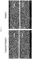
- Example 1 Cross-section SEM photographs for the negative electrode before compression according to Example 1 and Comparative Example 1 were measured. The results are shown in FIG. 3 as A and B.
- the white color on the center was the current collector, and the A and the B were negative active material layers on both sides of the current collector.
- the thickness value of the active material layer shown in FIG. 3 was the real measurement value.
- the active material layer was formed at a thickness of 130 ⁇ m adding the first negative active material layer and the second negative active material layer, but it was really obtained as 128 ⁇ m and 124 ⁇ m, respectively, depending on deviations caused during the preparation process. It is also considered that such a deviation will be readily understood in the related art.
- the B sides (B of FIG. 3 ) and the A sides (A of FIG. 3 ) of Example 1 and Comparative Example 1 had similar morphology, but it can be known that Example 1 had a degree of verticality, rather than Comparative Example 1.
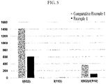
- the peak intensity I (002) and the peak intensity I (110) were measured. The results are shown in FIG 4 .
- the peak intensity ratio (I (002) /I (110) ) was measured.
- the results are also shown in FIG. 4 .
- the peak intensity measured in the experiment was obtained as the integral area value of the peak.
- the peak intensity ratio (I (002) /I (110) ) of Example 1 was 24 and the peak intensity ratio (I (002) /I (110) ) of Comparative Example 1 was 160, before compression.
- the peak intensity ratio (I (002) /I (110) ) of Example 1 was 116 and the peak intensity ratio (I (002) /I (110) ) of Comparative Example 1 was 370, after compression.
- the peak intensity ratio (I (002) /I (110) ) of the negative active material layer with applying the magnetic field was 150 or less, and it was 90 % or less relative to the peak intensity ratio (I (002) /I (110) ) of the negative active material layer without applying the magnetic field.
- the peak intensity I (002) and the peak intensity I (110) of the negative electrodes according to Examples 2 and 3 and Comparative Example 2 were measured under the same condition, and the peak intensity ratio (I (002) /I (110) ) was obtained from these results. The results are shown in FIG. 6 .
- the peak intensity ratio (I (002) /I (110) ) of Examples 1 and 2 are also shown in FIG. 6 .
- Example 1 was 116
- Example 2 was 142
- Example 3 was 110
- Comparative Example 1 was 370
- Comparative Example 2 was 505.
- the peak intensity ratios (I (002) /I (110) ) of Examples 1 to 3 were 150 or less, but the peak intensity ratios of Comparative Example 1 and Comparative Example 2 without orienting by the magnetic field were much more than 150.
- the peak intensity ratio (I (002) /I (110) ) is significantly different depending on performing/ not-performing the orientation by the magnetic field.
- the binder distribution of the top (second negative active material layer) and bottom (first negative active material layer) of the negative electrodes according to Example 1 and Comparative Examples 1 and 2 were confirmed by measuring peel strength.
- the peel strength measurement was determined by cutting the negative electrode with a blade using SAICAS (Surface And Interfacial Cutting Analysis System) equipment and separating into the bottom (first negative active material layer) and top (second negative active material layer). From the resulting peel strength of the top and the bottom, the percent ratio of peel strength of bottom/peel strength of top was measured. The results are shown in FIG. 7 .
- the A plane indicates the A plane of FIG. 3 and the B plane indicates the B plane of FIG. 3 .
- Example 1 and Comparative Example 1 had the percent ratio of peel strength of bottom/peel strength of top of the A plane and the B plane of 70 % or more (Example 1: A plane-75 %, B plane-76 %, Comparative Example 1: A plane-78 %, B plane-79 %), but Comparative Example 2 had about 50 %.
- the use amount of the binder in the first negative active material layer that is larger than in the second negative active material layer may allow uniform distribution of the binder throughout the active material layer.
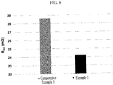
- ion resistance was measured by using an impedance analyzer (Solartron 1260A Impedance/Gain-Phase Analyzer) at 25 °C under a 2-probe method. The results are shown in FIG. 8 .
- Example 1 had significantly reduced rather than that of Comparative Example 1.
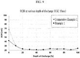
- the direct current internal resistance (DC-IR) for the rechargeable lithium batteries of Example 1 and Comparative Example 1 was evaluated by charging and discharging at 0.5C and under 25 °C while depth of discharge (ratio of discharge capacity to rated capacity) was changed into 0 %, 10 %, 20 %, 40 %, 50 %, 60 %, 70 %, 80 %, 90 %, and 100 %, and by measuring voltage drop (V), while a current flowed at 0.5 C for 10 seconds.
- V voltage drop
- Example 1 As shown in FIG. 9 , the resistance of Example 1 was totally lower than that of Comparative Example 1 and particularly, the resistance at the initial (0%) depth of discharge was significantly lower than that of Comparative Example 1.
- the rechargeable lithium batteries of Example 1, Comparative Example 1, and Comparative Example 2 were charged and discharged at 1.0 C under 4.2 V to 2.5 V and at a room temperature (RT, 25 °C) 100 times.
- a capacity retention depending on charge and discharge cycles was evaluated by calculating a discharge capacity ratio at each cycle relative to discharge capacity at the first cycle. The results are shown in FIG. 10 .
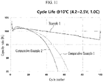
- the rechargeable lithium batteries of Example 1, Comparative Example 1, and Comparative Example 2 were charged and discharged at 1.0 C under 4.2 V to 2.5 V and at a low temperature (10 °C) 100 times. Capacity retention depending on charge and discharge cycles was evaluated by calculating a discharge capacity ratio at each cycle relative to discharge capacity at the first cycle. The results are shown in FIG. 11 .
- Example 1 exhibited excellent cycle-life characteristics at room temperature and a low temperature, rather than Comparative Example 1 and Comparative Example 2.
- Example 1 exhibited surprisingly excellent low temperature cycle-life characteristic compared to Comparative Example 1 and Comparative Example 2.
- Comparative Example 1 exhibited capacity retention of 85 % for 64 cycles at a low temperature and Comparative Example 2 exhibited capacity retention of 85 % for 50 cycles or more at a low temperature, and thus, the capacity retentions of Comparative Examples 1 and 2 were significantly deteriorated.
Landscapes
- Chemical & Material Sciences (AREA)
- Engineering & Computer Science (AREA)
- Chemical Kinetics & Catalysis (AREA)
- Electrochemistry (AREA)
- General Chemical & Material Sciences (AREA)
- Materials Engineering (AREA)
- Manufacturing & Machinery (AREA)
- Composite Materials (AREA)
- Inorganic Chemistry (AREA)
- Battery Electrode And Active Subsutance (AREA)
- Secondary Cells (AREA)
Applications Claiming Priority (1)
| Application Number | Priority Date | Filing Date | Title |
|---|---|---|---|
| KR1020210053157A KR20220146194A (ko) | 2021-04-23 | 2021-04-23 | 리튬 이차 전지용 음극 및 이를 포함하는 리튬 이차 전지 |
Publications (2)
| Publication Number | Publication Date |
|---|---|
| EP4080604A2 true EP4080604A2 (fr) | 2022-10-26 |
| EP4080604A3 EP4080604A3 (fr) | 2022-11-02 |
Family
ID=81346280
Family Applications (1)
| Application Number | Title | Priority Date | Filing Date |
|---|---|---|---|
| EP22169472.2A Pending EP4080604A3 (fr) | 2021-04-23 | 2022-04-22 | Électrode négative pour batterie rechargeable au lithium et batterie rechargeable au lithium la comprenant |
Country Status (5)
| Country | Link |
|---|---|
| US (3) | US12482853B2 (fr) |
| EP (1) | EP4080604A3 (fr) |
| JP (1) | JP7653388B2 (fr) |
| KR (1) | KR20220146194A (fr) |
| CN (1) | CN115241417B (fr) |
Cited By (3)
| Publication number | Priority date | Publication date | Assignee | Title |
|---|---|---|---|---|
| EP4447164A4 (fr) * | 2022-12-23 | 2025-03-19 | LG Energy Solution, Ltd. | Électrode négative pour batterie secondaire au lithium et son procédé de fabrication |
| EP4465380A4 (fr) * | 2022-11-25 | 2025-03-26 | LG Energy Solution, Ltd. | Anode pour batterie secondaire au lithium et son procédé de fabrication |
| EP4560724A4 (fr) * | 2023-06-15 | 2025-09-17 | Lg Energy Solution Ltd | Électrode négative pour batterie secondaire au lithium et son procédé de fabrication |
Families Citing this family (8)
| Publication number | Priority date | Publication date | Assignee | Title |
|---|---|---|---|---|
| EP4478446A4 (fr) * | 2022-12-07 | 2025-05-21 | LG Energy Solution, Ltd. | Électrode négative pour batterie secondaire au lithium et procédé pour la fabriquer |
| KR20240087999A (ko) * | 2022-12-13 | 2024-06-20 | 주식회사 엘지에너지솔루션 | 이차전지용 음극 제조장치 |
| KR102630462B1 (ko) * | 2022-12-23 | 2024-01-31 | 주식회사 엘지에너지솔루션 | 리튬 이차전지용 음극 및 이의 제조방법 |
| KR20240116201A (ko) * | 2023-01-20 | 2024-07-29 | 에스케이온 주식회사 | 리튬 이차 전지용 음극 및 이를 포함하는 리튬 이차 전지 |
| JP2025066317A (ja) * | 2023-10-11 | 2025-04-23 | トヨタ自動車株式会社 | 電池用電極、電池、および、電池用電極の製造方法 |
| KR20250069205A (ko) * | 2023-11-10 | 2025-05-19 | 삼성에스디아이 주식회사 | 이차 전지용 음극 및 이를 포함하는 이차 전지 |
| KR20250097199A (ko) * | 2023-12-21 | 2025-06-30 | 에스케이온 주식회사 | 이차전지용 음극 및 이를 포함하는 리튬 이차전지 |
| WO2026023958A1 (fr) * | 2024-07-24 | 2026-01-29 | 주식회사 엘지에너지솔루션 | Anode pour batterie secondaire au lithium et son procédé de fabrication |
Family Cites Families (17)
| Publication number | Priority date | Publication date | Assignee | Title |
|---|---|---|---|---|
| KR100269918B1 (ko) | 1997-08-28 | 2000-10-16 | 김순택 | 리튬 계열 이차 전지의 음극용 활물질 및 그의 제조 방법 |
| US7326497B2 (en) | 2001-12-21 | 2008-02-05 | Samsung Sdi Co., Ltd. | Graphite-containing composition, negative electrode for a lithium secondary battery, and lithium secondary battery |
| JP4150516B2 (ja) | 2001-12-21 | 2008-09-17 | 三星エスディアイ株式会社 | リチウム二次電池の負極用の黒鉛含有組成物の製造方法並びにリチウム二次電池用の負極の製造方法及びリチウム二次電池の製造方法 |
| JP2003297353A (ja) | 2002-03-29 | 2003-10-17 | Nec Corp | 二次電池用負極およびそれを用いた二次電池ならびに二次電池用負極の製造方法 |
| JP5900113B2 (ja) | 2012-03-30 | 2016-04-06 | ソニー株式会社 | リチウムイオン二次電池、リチウムイオン二次電池用負極、電池パック、電子機器、電動車両、蓄電装置および電力システム |
| JP5724931B2 (ja) | 2012-04-03 | 2015-05-27 | トヨタ自動車株式会社 | 非水電解質二次電池、及びその製造方法 |
| JP2015138644A (ja) | 2014-01-22 | 2015-07-30 | トヨタ自動車株式会社 | 非水電解質二次電池 |
| KR101874150B1 (ko) | 2014-09-03 | 2018-07-04 | 재단법인 철원플라즈마 산업기술연구원 | 고배향성 판상흑연 시트 |
| KR102484406B1 (ko) | 2016-11-01 | 2023-01-02 | 삼성에스디아이 주식회사 | 리튬 이차 전지용 음극 및 이를 포함하는 리튬 이차 전지 |
| KR102483995B1 (ko) | 2016-12-07 | 2022-12-30 | 삼성에스디아이 주식회사 | 이차 전지용 음극 및 그의 제조 방법 |
| JP6848657B2 (ja) | 2017-05-01 | 2021-03-24 | トヨタ自動車株式会社 | 非水系電池およびその製造方法 |
| KR101972235B1 (ko) | 2017-10-25 | 2019-08-23 | 재단법인대구경북과학기술원 | 리튬이차전지 음극 제조방법 및 리튬이차전지 제조방법 |
| KR102417774B1 (ko) | 2018-04-20 | 2022-07-05 | 삼성에스디아이 주식회사 | 리튬 이차 전지용 음극 및 이를 포함하는 리튬 이차 전지 |
| KR102417773B1 (ko) | 2018-04-27 | 2022-07-05 | 삼성에스디아이 주식회사 | 리튬 이차 전지용 음극 및 이를 포함하는 리튬 이차 전지 |
| KR102570570B1 (ko) | 2019-04-24 | 2023-08-23 | 삼성에스디아이 주식회사 | 리튬 이차 전지용 음극 및 이를 포함하는 리튬 이차 전지 |
| KR102536366B1 (ko) | 2019-04-24 | 2023-05-23 | 삼성에스디아이 주식회사 | 리튬 이차 전지용 음극 및 이를 포함하는 리튬 이차 전지 |
| KR102935733B1 (ko) | 2019-06-03 | 2026-03-05 | 삼성에스디아이 주식회사 | 리튬 이차 전지용 음극 및 이를 포함하는 리튬 이차 전지 |
-
2021
- 2021-04-23 KR KR1020210053157A patent/KR20220146194A/ko active Pending
-
2022
- 2022-04-20 US US17/660,004 patent/US12482853B2/en active Active
- 2022-04-22 CN CN202210430096.XA patent/CN115241417B/zh active Active
- 2022-04-22 EP EP22169472.2A patent/EP4080604A3/fr active Pending
- 2022-04-25 JP JP2022071475A patent/JP7653388B2/ja active Active
-
2025
- 2025-06-17 US US19/241,336 patent/US20250309334A1/en active Pending
- 2025-09-17 US US19/331,885 patent/US20260018657A1/en active Pending
Cited By (3)
| Publication number | Priority date | Publication date | Assignee | Title |
|---|---|---|---|---|
| EP4465380A4 (fr) * | 2022-11-25 | 2025-03-26 | LG Energy Solution, Ltd. | Anode pour batterie secondaire au lithium et son procédé de fabrication |
| EP4447164A4 (fr) * | 2022-12-23 | 2025-03-19 | LG Energy Solution, Ltd. | Électrode négative pour batterie secondaire au lithium et son procédé de fabrication |
| EP4560724A4 (fr) * | 2023-06-15 | 2025-09-17 | Lg Energy Solution Ltd | Électrode négative pour batterie secondaire au lithium et son procédé de fabrication |
Also Published As
| Publication number | Publication date |
|---|---|
| US20250309334A1 (en) | 2025-10-02 |
| US20260018657A1 (en) | 2026-01-15 |
| US12482853B2 (en) | 2025-11-25 |
| JP7653388B2 (ja) | 2025-03-28 |
| US20220352543A1 (en) | 2022-11-03 |
| CN115241417B (zh) | 2025-12-19 |
| JP2022167890A (ja) | 2022-11-04 |
| EP4080604A3 (fr) | 2022-11-02 |
| CN115241417A (zh) | 2022-10-25 |
| KR20220146194A (ko) | 2022-11-01 |
Similar Documents
| Publication | Publication Date | Title |
|---|---|---|
| US12237496B2 (en) | Negative electrode for lithium secondary battery and lithium secondary battery comprising same | |
| EP4080604A2 (fr) | Électrode négative pour batterie rechargeable au lithium et batterie rechargeable au lithium la comprenant | |
| US12155057B2 (en) | Anode for lithium secondary battery and lithium secondary battery comprising same | |
| EP3561914B1 (fr) | Électrode négative pour batterie rechargeable au lithium et batterie rechargeable au lithium l'incluant | |
| US11296323B2 (en) | Positive electrode for lithium secondary battery and lithium secondary battery comprising same | |
| US20110165465A1 (en) | Negative active material for rechargeable lithium battery, method of preparing same, and rechargeable lithium battery including same | |
| US12237510B2 (en) | Negative electrode for a rechargeable lithium battery and rechargeable lithium battery including the same | |
| EP3930046A1 (fr) | Électrode négative pour batterie rechargeable au lithium et batterie rechargeable au lithium comprenant celle-ci | |
| US20120183853A1 (en) | Positive Active Material for Rechargeable Lithium Battery, Method of Manufacturing the Same and Rechargeable Lithium Battery Using the Same | |
| US9023532B2 (en) | Positive active material composition for rechargeable lithium battery, positive electrode for rechargeable lithium battery including the positive active material composition, and rechargeable lithium battery including the positive active material composition | |
| EP4213233A1 (fr) | Électrode négative pour batterie secondaire au lithium et batterie secondaire au lithium la comprenant | |
| US20240372096A1 (en) | Anode for lithium secondary battery and lithium secondary battery comprising same | |
| US20230178721A1 (en) | Negative electrode for lithium secondary battery and lithium secondary battery comprising same | |
| US20200028177A1 (en) | Lithium secondary battery cathode and lithium secondary battery including same | |
| EP4411847A1 (fr) | Électrode négative pour batterie au lithium rechargeable et batterie au lithium rechargeable la comprenant | |
| EP3940813B1 (fr) | Matériau actif négatif pour batterie au lithium rechargeable et batterie au lithium rechargeable le comprenant | |
| US20240363861A1 (en) | Negative electrode for lithium secondary battery and lithium secondary battery comprising same | |
| EP4365978A2 (fr) | Électrode négative pour batterie au lithium rechargeable et batterie au lithium rechargeable la comprenant | |
| US11335906B2 (en) | Negative active material for rechargeable lithium battery, and rechargeable lithium battery including same | |
| US20230327203A1 (en) | Lithium secondary battery |
Legal Events
| Date | Code | Title | Description |
|---|---|---|---|
| PUAI | Public reference made under article 153(3) epc to a published international application that has entered the european phase |
Free format text: ORIGINAL CODE: 0009012 |
|
| STAA | Information on the status of an ep patent application or granted ep patent |
Free format text: STATUS: REQUEST FOR EXAMINATION WAS MADE |
|
| PUAL | Search report despatched |
Free format text: ORIGINAL CODE: 0009013 |
|
| 17P | Request for examination filed |
Effective date: 20220422 |
|
| AK | Designated contracting states |
Kind code of ref document: A2 Designated state(s): AL AT BE BG CH CY CZ DE DK EE ES FI FR GB GR HR HU IE IS IT LI LT LU LV MC MK MT NL NO PL PT RO RS SE SI SK SM TR |
|
| AK | Designated contracting states |
Kind code of ref document: A3 Designated state(s): AL AT BE BG CH CY CZ DE DK EE ES FI FR GB GR HR HU IE IS IT LI LT LU LV MC MK MT NL NO PL PT RO RS SE SI SK SM TR |
|
| RIC1 | Information provided on ipc code assigned before grant |
Ipc: H01M 4/587 20100101ALI20220929BHEP Ipc: H01M 4/36 20060101ALI20220929BHEP Ipc: H01M 4/1393 20100101ALI20220929BHEP Ipc: H01M 4/133 20100101AFI20220929BHEP |
|
| STAA | Information on the status of an ep patent application or granted ep patent |
Free format text: STATUS: EXAMINATION IS IN PROGRESS |
|
| 17Q | First examination report despatched |
Effective date: 20240410 |