EP4080631A1 - Module de puissance de pile à combustible - Google Patents
Module de puissance de pile à combustible Download PDFInfo
- Publication number
- EP4080631A1 EP4080631A1 EP21315067.5A EP21315067A EP4080631A1 EP 4080631 A1 EP4080631 A1 EP 4080631A1 EP 21315067 A EP21315067 A EP 21315067A EP 4080631 A1 EP4080631 A1 EP 4080631A1
- Authority
- EP
- European Patent Office
- Prior art keywords
- fuel cell
- compartment
- module according
- power
- sealed
- Prior art date
- Legal status (The legal status is an assumption and is not a legal conclusion. Google has not performed a legal analysis and makes no representation as to the accuracy of the status listed.)
- Withdrawn
Links
- 239000000446 fuel Substances 0.000 title claims abstract description 127
- 238000005192 partition Methods 0.000 claims abstract description 30
- 239000012530 fluid Substances 0.000 claims abstract description 8
- UFHFLCQGNIYNRP-UHFFFAOYSA-N Hydrogen Chemical compound [H][H] UFHFLCQGNIYNRP-UHFFFAOYSA-N 0.000 claims description 36
- 239000001257 hydrogen Substances 0.000 claims description 35
- 229910052739 hydrogen Inorganic materials 0.000 claims description 35
- 239000007789 gas Substances 0.000 claims description 23
- 238000001816 cooling Methods 0.000 claims description 18
- 239000007788 liquid Substances 0.000 claims description 16
- 239000002826 coolant Substances 0.000 claims description 11
- XLYOFNOQVPJJNP-UHFFFAOYSA-N water Substances O XLYOFNOQVPJJNP-UHFFFAOYSA-N 0.000 claims description 10
- 239000000498 cooling water Substances 0.000 claims description 5
- QVGXLLKOCUKJST-UHFFFAOYSA-N atomic oxygen Chemical compound [O] QVGXLLKOCUKJST-UHFFFAOYSA-N 0.000 claims description 4
- 238000009396 hybridization Methods 0.000 claims description 4
- 239000001301 oxygen Substances 0.000 claims description 4
- 229910052760 oxygen Inorganic materials 0.000 claims description 4
- 238000007599 discharging Methods 0.000 claims description 2
- 210000004027 cell Anatomy 0.000 description 102
- 238000009423 ventilation Methods 0.000 description 11
- MYMOFIZGZYHOMD-UHFFFAOYSA-N Dioxygen Chemical compound O=O MYMOFIZGZYHOMD-UHFFFAOYSA-N 0.000 description 4
- 229910001882 dioxygen Inorganic materials 0.000 description 4
- 239000002360 explosive Substances 0.000 description 4
- 239000002737 fuel gas Substances 0.000 description 4
- 231100001261 hazardous Toxicity 0.000 description 4
- 239000012528 membrane Substances 0.000 description 4
- OKKJLVBELUTLKV-UHFFFAOYSA-N Methanol Chemical compound OC OKKJLVBELUTLKV-UHFFFAOYSA-N 0.000 description 3
- 238000004590 computer program Methods 0.000 description 3
- 238000004880 explosion Methods 0.000 description 3
- 150000002431 hydrogen Chemical class 0.000 description 3
- QGZKDVFQNNGYKY-UHFFFAOYSA-N Ammonia Chemical compound N QGZKDVFQNNGYKY-UHFFFAOYSA-N 0.000 description 2
- NBIIXXVUZAFLBC-UHFFFAOYSA-N Phosphoric acid Chemical compound OP(O)(O)=O NBIIXXVUZAFLBC-UHFFFAOYSA-N 0.000 description 2
- ATUOYWHBWRKTHZ-UHFFFAOYSA-N Propane Chemical compound CCC ATUOYWHBWRKTHZ-UHFFFAOYSA-N 0.000 description 2
- 238000006243 chemical reaction Methods 0.000 description 2
- 239000002131 composite material Substances 0.000 description 2
- 230000005611 electricity Effects 0.000 description 2
- 238000004146 energy storage Methods 0.000 description 2
- 238000001914 filtration Methods 0.000 description 2
- 239000007800 oxidant agent Substances 0.000 description 2
- 230000003647 oxidation Effects 0.000 description 2
- 238000007254 oxidation reaction Methods 0.000 description 2
- 238000006722 reduction reaction Methods 0.000 description 2
- 238000007789 sealing Methods 0.000 description 2
- BVKZGUZCCUSVTD-UHFFFAOYSA-L Carbonate Chemical compound [O-]C([O-])=O BVKZGUZCCUSVTD-UHFFFAOYSA-L 0.000 description 1
- 238000009825 accumulation Methods 0.000 description 1
- 229910000147 aluminium phosphate Inorganic materials 0.000 description 1
- 229910021529 ammonia Inorganic materials 0.000 description 1
- 239000001273 butane Substances 0.000 description 1
- 239000003990 capacitor Substances 0.000 description 1
- 210000003850 cellular structure Anatomy 0.000 description 1
- 230000001276 controlling effect Effects 0.000 description 1
- 230000007797 corrosion Effects 0.000 description 1
- 238000005260 corrosion Methods 0.000 description 1
- 238000001035 drying Methods 0.000 description 1
- 238000005868 electrolysis reaction Methods 0.000 description 1
- 239000003063 flame retardant Substances 0.000 description 1
- 238000009434 installation Methods 0.000 description 1
- 230000010354 integration Effects 0.000 description 1
- 239000003014 ion exchange membrane Substances 0.000 description 1
- 210000001503 joint Anatomy 0.000 description 1
- 230000007257 malfunction Effects 0.000 description 1
- 230000000116 mitigating effect Effects 0.000 description 1
- IJDNQMDRQITEOD-UHFFFAOYSA-N n-butane Chemical compound CCCC IJDNQMDRQITEOD-UHFFFAOYSA-N 0.000 description 1
- OFBQJSOFQDEBGM-UHFFFAOYSA-N n-pentane Natural products CCCCC OFBQJSOFQDEBGM-UHFFFAOYSA-N 0.000 description 1
- 230000001590 oxidative effect Effects 0.000 description 1
- 239000002245 particle Substances 0.000 description 1
- 239000005518 polymer electrolyte Substances 0.000 description 1
- 239000001294 propane Substances 0.000 description 1
- 230000001105 regulatory effect Effects 0.000 description 1
- 238000000926 separation method Methods 0.000 description 1
- 239000007787 solid Substances 0.000 description 1
- 238000000638 solvent extraction Methods 0.000 description 1
Images

Classifications
-
- H—ELECTRICITY
- H01—ELECTRIC ELEMENTS
- H01M—PROCESSES OR MEANS, e.g. BATTERIES, FOR THE DIRECT CONVERSION OF CHEMICAL ENERGY INTO ELECTRICAL ENERGY
- H01M8/00—Fuel cells; Manufacture thereof
- H01M8/24—Grouping of fuel cells, e.g. stacking of fuel cells
- H01M8/2465—Details of groupings of fuel cells
- H01M8/247—Arrangements for tightening a stack, for accommodation of a stack in a tank or for assembling different tanks
- H01M8/2475—Enclosures, casings or containers of fuel cell stacks
-
- Y—GENERAL TAGGING OF NEW TECHNOLOGICAL DEVELOPMENTS; GENERAL TAGGING OF CROSS-SECTIONAL TECHNOLOGIES SPANNING OVER SEVERAL SECTIONS OF THE IPC; TECHNICAL SUBJECTS COVERED BY FORMER USPC CROSS-REFERENCE ART COLLECTIONS [XRACs] AND DIGESTS
- Y02—TECHNOLOGIES OR APPLICATIONS FOR MITIGATION OR ADAPTATION AGAINST CLIMATE CHANGE
- Y02E—REDUCTION OF GREENHOUSE GAS [GHG] EMISSIONS, RELATED TO ENERGY GENERATION, TRANSMISSION OR DISTRIBUTION
- Y02E60/00—Enabling technologies; Technologies with a potential or indirect contribution to GHG emissions mitigation
- Y02E60/30—Hydrogen technology
- Y02E60/50—Fuel cells
Definitions
- the present invention relates to a fuel cell power module.
- it relates to a fuel cell power module for marine applications.
- the present invention relates a hydrogen storage and power system comprising such fuel cell power module.
- a fuel cell power module is a device that generates electrical power from a fuel and oxidant. Electricity is generated through the oxidation of a reducing-fuel on an electrode (anode), for example hydrogen, coupled with the reduction on the other electrode (cathode) of an oxidiser, normally oxygen extracted from an air supply.
- the fuel cell power module can be constituted of a plurality of cells connected in series to reach the desired power output.
- the integration of the fuel cell power modules is a key element to ensure the safe operation and reliability of the fuel cell system throughout its service life in a vehicle, boat or stationary power application.
- the fuel cell systems can however be quite complex to install, as they comprise a large number of components.
- the module comprises a chamber split into a first 120 and a second compartment.
- the first compartment houses an air pump, the hydrogen inlet/outlet, hydrogen valves, electrical components, and a set of filters to receive a filtered airflow into the chamber.
- the second compartment houses a stack of fuel cells and a humidification.
- the chamber is provided with partitions which form a conduit to allow cooling air to be suctioned through the stack of fuel cells by a cooling ventilator. The partitions are sealed to prevent the gases and the liquids mixing between compartments.
- Another objective of the present invention is to provide a fuel cell power module containing as much of the fuel cell systems as possible while still minimizing potential risk of ignition in order to be suitable for marine applications.
- Another objective of the present invention is to provide a fuel cell power module avoiding the need to be installed in a specific, enclosed and sealed room, and therefore could be installed anywhere inside a vessel.
- a fuel cell power module of the present invention enables the safety system for the fuel cell power system to be standardised and controlled, irrespective of the vessel, vehicle, or other application where it is installed.
- a fuel cell power module housed in a sealed casing (2) that is subdivided into separate enclosed compartments by a sealed partition (21) with one of the said compartments being an electric compartment (3) comprising power management components (31, 32, 33), the other being a fuel cell compartment (4) comprising a fuel cell (41) and its inlet and outlet circuits containing flammable fluids.
- the module can be made up of one continuous structure or multiple structures joined together.
- cables and non-flammable fluids and associated piping may pass through the partition of the module via sealed junctions through the partition to maintain separate air spaces between compartments.
- the fuel cell compartment may include additional components such as balance of plant components e.g. a compressor (43) and/or a liquid coolant filter (45) and/or a liquid coolant pump (46) and/or a thermostatic tap (47) which may be required for operation of the hydrogen fuel cell or for providing additional module functionality.
- additional components such as balance of plant components e.g. a compressor (43) and/or a liquid coolant filter (45) and/or a liquid coolant pump (46) and/or a thermostatic tap (47) which may be required for operation of the hydrogen fuel cell or for providing additional module functionality.
- the sealed partition is only passed through by the power management connection cables (c1, c2).
- the sealed partition is only passed through by a fuel cell cathode gas inlet conduit (cO2f).
- the sealed partition is only passed through by power management connection cables (c1, c2) and/or a cathode gas conduit (cO2f) of which the inlet opens into the electric compartment and which is connected to the air supply system of the fuel cell (41), and/or a pipe cCoolFPT and pipe cHot respectively providing cooling water to the fuel cell 41 and discharging cooling water from the fuel cell.
- a fuel cell power module may be provided wherein the pressure within the fuel cell compartment is kept lower than the electrical compartment and/or lower than the surrounding space outside of the module in order to provide an additional layer of safety.
- a fuel cell power module may be provided, where multiple fuel cells are present in the fuel cell space sharing a common fuel inlet and exhaust in order to increase power output without compromising the efficiency of the module in terms of cost per kW, weight/size per kW, and overall energy efficiency (kWh of electrical energy produced per kg of hydrogen used).
- a fuel cell power module is provided, formed of a sealed casing (2) separated into two compartments (3, 4) by a sealed partition (21), one of said two compartments being an electric compartment (3) comprising a system controller (31), the other being a cell compartment (4) comprising a fuel cell (41) arranged to be supplied with hydrogen by a hydrogen supply system connected to a hydrogen inlet connection (iH2), supplied with oxygen by an air supply system connected to an air inlet connection (iO2), to repel gases by a gas discharge system connected to a repel connection (iGaz), to repel water through a water discharge system connected to a repel connection (iH20), and provided to be cooled by a liquid cooling system connected to a cooling connection (iCool).
- a fuel cell power module of the present invention may comprise a power management system adapted to regulate voltage and current so that the power output can be connected directly to the load application, controlling hybridisation, and avoiding the need for external electrical regulation.
- the casing (2) of the fuel cell power module may be adapted to enable multiple modules to be safely combined and/or stacked vertically, one on top of the other, without additional supporting structure or cabinets.
- a hydrogen storage and power system comprising a fuel cell power module as described in accordance with the present invention.
- Such hydrogen storage and power system may be suitable for being installed in high safety requiring applications, such as marine applications and in particular vessels.
- variants of the invention only comprising a selection of features described can in particular be considered, subsequently isolated from the other features described, if this selection of features is sufficient to give a technical advantage or to differentiate the invention with respect to the prior art.
- This selection comprises at least one feature, preferably operational without structural details, or with only some of the structural details if this part only is sufficient to give a technical advantage or to differentiate the invention with respect to the prior art.
- a fuel cell power module is described below (1), said module housed in a sealed casing (2) that is subdivided into separate enclosed compartments by a sealed partition (21) with one of the said compartments being an electric compartment (3) comprising power management components (31, 32, 33), the other being a fuel cell compartment under forced ventilation (4) comprising a fuel cell (41) and its inlet and outlet circuits containing flammable fluids.
- This arrangement prevents potential explosive fuel gases present in the fuel cell compartment from circulating in the electric compartment and thus avoids associated risk of ignition from electrical components.
- forced ventilation systems integrated into the module ensures that concentrations of explosive gas resulting from component leakage are kept well below the lower explosion limit (LEL) of the gas.
- LEL lower explosion limit
- the forced air ventilation systems are controlled so as to ensure that the pressure in the non-hazardous, electrical compartment is higher than that of the hazardous fuel cell compartment, so as to provide an additional level of safety against potential fuel gas intrusion.
- the pressure in the hazardous fuel cell compartment is kept at a lower pressure than the space external to the module, in addition to the adjacent electrical compartment, to add a level of safety to the fuel gas escaping outside of the fuel cell module.
- the casing of the module protects and contains as much of the fuel cell systems as possible, that meet the air-tight safety requirements of the fuel cell space.
- the module is connected to ventilation pipes that lead outside of the vessel, it avoids the need to be installed in a specific, enclosed and sealed room (as is the case with the "fuel cell in a cage” approach), and can in principle be installed anywhere inside a vessel.
- the module ensures that the ventilation flow rates are sufficiently high, consistent and controlled for any vessel, to meet safety criteria and prevent build-up of hydrogen.
- the module enables the safety system to be standardised and controlled for the fuel cell power system, irrespective of the vessel, vehicle, or other application, where it is installed.
- the sealed partition is passed through by control, power, and other electrical cables (c1, c2) principally connecting the fuel cells with the power management components.
- the sealed partition is passed through additionally by a -fuel cell cathode gas inlet pipe (cO2f).
- This fuel cell cathode gas inlet conduit keeps the cathode gas, which is typically air, separated from the space of the fuel cell compartment and is sealed into the partition.
- the fuel cell cathode gas inlet conduit opens into the electric compartment and is connected to the air supply system of the fuel cell. This may assist in cooling of the power management components.
- the sealed partition may be bypassed by other non-flammable fluid conduits connected to the fuel cell. These conduits are sealed to prevent fluid leakage between the fuel cell ventilated space and the air space of the electrical compartment.
- the electrical compartment may contain a voltage converter that may be liquid-cooled from coolant bypassing the sealed partition that is connected to the fuel cell cooling system.
- the power management system integrated into the module outputs electrical power at a specific voltage that is regulated in order to be compatible with the external application load, as so avoids the need for an additional external voltage converter.
- the power management system also controls the current output from the module so as to control the hybridisation with an external battery pack for maximising fuel efficiency and fuel cell stack lifetime.
- the fuel cell compartment may include balance of plant components such as a compressor (43) and/or a liquid coolant filter (45) and/or a liquid coolant pump (46) and/or a thermostatic tap (47)) for a hydrogen fuel cell, e.g. hydrogen gas pipework and devices, a cathode gas inlet compressor, and a liquid cooling pump.
- plant components such as a compressor (43) and/or a liquid coolant filter (45) and/or a liquid coolant pump (46) and/or a thermostatic tap (47) for a hydrogen fuel cell, e.g. hydrogen gas pipework and devices, a cathode gas inlet compressor, and a liquid cooling pump.
- the pressure within the electrical compartment may be kept higher than the pressure within the fuel cell compartment, so mitigating risk of possible hydrogen transfer across the partition in the event of joint damage or failure, for example by adding input ventilation fans in the electrical compartment.
- the electrical compartment may contain an electrical energy storage system in the way of a battery or supercapacitor that is charged from the fuel cell and that can be used for start-up, rapid power response, or peak power response if hybridised with the fuel cell.
- multiple fuel cells may be present in the fuel cell compartment sharing a common fuel inlet and exhaust.
- a fuel cell power module in accordance with the present invention mitigates the risk of ignition by ensuring that all non-explosion rated electrical components (non-ATEX-rated) are housed in a separate compartment i.e. the electrical compartment.
- the separation of non-ATEX electrical and fuel cell components by the sealed partition of the module ensures there is mitigated risk of explosive gas coming into contact with these electrical components, which can include system controllers, voltage converters, and energy storage components such as batteries or capacitors.
- the present invention further mitigates risk of ignition by providing forced ventilation in the fuel cell space from potential leakage of fuel system valves, connecters and piping, to ensure fuel gas concentration is kept well below the lower explosion limit.
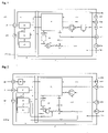
- the casing 2 is a rigid casing that is both watertight and airtight.
- the casing can be made of a composite material as a monocoque structure that avoids the need of a separate stiffening frame.
- the casing can be made of fire-retardant composite materials.
- the casing 2 is separated into two compartments 3 and 4 by a sealed partition 21.
- the compartment 3 is equipped with electric and electronic components, while the compartment 4 is equipped with a hydrogen fuel cell 41. This arrangement prevents possible hydrogen gas present in the compartment 4 from circulating the electric and electronic components, present in compartment 3, and thus minimising potential ignition risk.
- the compartment 3 is ventilated by means of an air inlet i3Air and an air outlet o3Air disposed at the interface between the outside of the casing 2 and the inside of the compartment 3.
- the compartment 3 comprises a system controller 31 connected to one or more control interfaces Ci outside of the casing 3 by means of a rapid connection iCi disposed on the outer surface of the casing 2.
- the system controller comprises a computer program product to control the operation of the fuel cell 41 by means of a connecting cable c1.
- the connecting cable c1 passes through the sealed partition 5.
- the sealing to gas is conserved.
- the electric compartment 3 further comprises a power control unit 32.
- the power control unit 32 is connected to power current interfaces HPi outside of the compartment 3 by means of a rapid connection iHPi disposed on the outside surface of the casing 2.
- the power control unit 32 converts high-power voltage, for example by means of a DC/DC converter to a required output voltage.
- control unit 32 When such a control unit 32 is present, it is further connected to the system controller 31 by means of a connecting cable c2.
- the computer program of the system controller 31 thus controls the power control unit 32.
- the power control unit 32 can also regulate the quantity of power produced by the fuel cell 41, according to the instructions of the system controller 31.
- the system controller 31 is further configured to read/control all the other electronic devices which could exist inside the fuel cell power module (solenoid valves, hydrogen sensors, thermostats, etc.), and external to the module (battery management systems, motor controllers, hydrogen reservoir pressure, solenoid valves etc.).
- the electric compartment 3 further comprises an energy reserve 33, for example a battery or a supercapacitor, which is optional.
- an energy reserve 33 for example a battery or a supercapacitor, which is optional.
- the power control unit when it is present, by means of a connecting cable c4.
- the system controller 31 can be further connected to the system controller 31 by means of a connecting cable c4.
- the computer program of the system controller 31 thus controls the hybridisation between the energy provided by the fuel cell 41 and the energy reserve 33.
- the fuel cell compartment 4 is ventilated by means of an air inlet i4Air and an air outlet o4Air disposed at the interface between the outside of the casing 2 and the inside of the casing 4. This ventilation allows to guarantee a rapid discharge of the hydrogen in case of leakage and prevent accumulation.
- the fuel cell 41 comprises a succession of elementary cells (not represented), disposed to the side of one another.
- Each of these cells defines an anodic compartment, where oxidation from hydrogen is produced, as well as a cathodic compartment, wherein oxygen from the air is reduced, with water produced.
- an ion exchange membrane physically separates the anodic and cathodic compartments of a cell in question, which are moreover connected by means of an external electric circuit.
- a hydrogen flow is provided by a hydrogen supply pipe cH2 forming part of a hydrogen supply system.
- the hydrogen supply system can comprise a pressure regulator.
- the hydrogen gas system can also comprise overpressure valves and solenoid valves.
- the gas pipe cH2 can be connected to a hydrogen source sH2 outside of the compartment 4 by means of a rapid hydrogen connection iH2 disposed at the interface of the compartment 4 on the outer surface of the casing 2.
- the hydrogen flow is directed towards the anode side of the membrane/electrode assembly.
- the hydrogen is oxidised catalytically at the anode to give protons and electrons, according to the following electrochemical half-reaction: 2 H 2 ⁇ 4 H + + 4 e - .
- a dioxygen flow is provided by an air supply pipe cO2fc forming part of a dioxygen supply system.
- the pipe c02fc is connected to the outlet of a compressor 43 forming part of the air supply system, which pressurises a gas, at the air inlet pressure required for the fuel cell 41.
- the compressor is an optional element.
- the air inlet of the compressor 43, or the pipe c02fc, is connected by means of a pipe c02f at the outlet of an air filter 44 which forms part of the air supply system.
- the air filter is an optional element.
- the inlet of the air filter when the air filter is present, can be connected to an air source s02 outside of the compartment 4 by means of a pipe c02 connected to a rapid air inlet connection i02 disposed at the interface of the compartment 4 on the outer surface of the casing 2.
- the air supply system can further comprise additional filtration, humidifiers, air cooling systems or also flow sensors.
- the dioxygen flow is directed from the cathode side of the membrane/electrode.
- the dioxygen molecules react with the protons passing through the polymer electrolyte membrane and the electrons arriving through the external circuit in order to form water molecules.
- This reduction reaction in the electrolytic half-cell is written: 0 2 + 4 H + + 4 e - ⁇ 2 H 2 0 .
- the electric current produced is connected to the power control unit 32 by means of an electric cable c3.
- the connecting cable c3 passes through the sealed partition 21. The sealing to gas is conserved.
- the water molecules produced by the fuel cell 41, as well as excess air and hydrogen are removed from the fuel cell 41 via the gas removal pipe cGaz.
- the gas pipe cGaz can be connected to an outlet sGaz outside of the casing 2 by means of a rapid connection iGaz disposed at the interface of the compartment 4 on the outer surface of the casing 2.
- the fuel cell 41 is cooled by a liquid cooling system comprising a pipe cCoolFPT which provides cooling water to the fuel cell 41.
- the liquid cooling system further comprises a liquid coolant filter 45 of which the outlet is connected to the pipe cCoolFPT and of which the inlet is connected to a pipe cCooIPT.
- the liquid cooling system comprises a pump 46 of which the outlet is connected to the pipe cCoolPT and of which the inlet is supplied by a pipe cCoolT.
- the heat produced by the fuel cell 41 is principally discharged through the cooling outlet pipe cHot of a water discharge system.
- the pipe cHot can be connected to an outlet sHot outside of the compartment 4 by means of a rapid cooling connection iHot disposed at the interface of the compartment 4 on the outer surface of the casing 2.
- the liquid cooling system comprises a thermostatic tap 47 to regulate fuel cell temperature, of which the outlet is connected to the pipe cCoolT, and of which the inlets are connected to an external cold coolant pipe cCool, and the internally-circulated hot coolant pipe, cHot_int.
- the coolant pipe cCool can be connected to a source sCool outside of the compartment 4 by means of a rapid connection iCool disposed at the interface of the compartment 4 on the outer surface of the casing 2.
- the liquid cooling system can further comprise particle filters, deionisation filters, flow sensors, refilling tank, and a heat exchanger.
- the air supply sO2 passes through the filter 44 which is moved into the electric compartment 3.
- the conduit c02f which provides air to the cell opens into the electric compartment 3 to return the prefiltered air from the electronic compartment.
- the advantage of this system is to use the air filter of the fuel cell to protect the electric components from corrosion and to ensure their longevity.
- the connection i02 is also moved to the interface of the electric compartment 3.
- the filter can typically also be embedded or connected directly to the casing 2 at the opening i02, with air drawn in from the atmosphere outside of the casing 2.
- All air ventilation connections to the casing can include fans to control the compartment ventilation rates and differential pressures between compartments.
- electric connections, the air inlet pipe, and water cooling to the power management system pass through the sealed partition 21.
- the interfaces for the air inlets and air outlets are placed on opposite faces of the casing 1 or on one single side, such that the modules can be stacked ⁇ either side-by-side, or one top of one another in rack format.
- FIG 3 illustrates a fuel cell power system comprising several fuel cell power modules 1, 1', 1" of which the power outlets are connected directly in parallel to the main electrical bus that supplies the application load 200, typically an electrical propulsion system, and where fuel is fed to the modules from a common fuel storage system 201.
- Direct connectivity is achieved as a result of the internal voltage regulation of each module, ensuring a common voltage, V, and thus avoiding the need for external voltage regulator.
- the total power P T provided to the load is simply is a sum of the power output from each module (P + P' + P").
- This modular arrangement provides the advantage of redundancy in case of a malfunction of a single module, and the ability to have differential powers between modules so as to optimise the fuel efficiency of the entire system, or to shut down certain modules, again for increasing efficiency.
Landscapes
- Life Sciences & Earth Sciences (AREA)
- Engineering & Computer Science (AREA)
- Manufacturing & Machinery (AREA)
- Sustainable Development (AREA)
- Sustainable Energy (AREA)
- Chemical & Material Sciences (AREA)
- Chemical Kinetics & Catalysis (AREA)
- Electrochemistry (AREA)
- General Chemical & Material Sciences (AREA)
- Fuel Cell (AREA)
Priority Applications (6)
| Application Number | Priority Date | Filing Date | Title |
|---|---|---|---|
| EP21315067.5A EP4080631A1 (fr) | 2021-04-19 | 2021-04-19 | Module de puissance de pile à combustible |
| EP22723599.1A EP4327385A1 (fr) | 2021-04-19 | 2022-04-19 | Module d'alimentation de pile à combustible |
| PCT/EP2022/060277 WO2022223537A1 (fr) | 2021-04-19 | 2022-04-19 | Module d'alimentation de pile à combustible |
| US18/287,401 US20240204229A1 (en) | 2021-04-19 | 2022-04-19 | A fuel cell power module |
| JP2023562967A JP2024514629A (ja) | 2021-04-19 | 2022-04-19 | 燃料電池パワーモジュール |
| CN202280035928.6A CN117355968A (zh) | 2021-04-19 | 2022-04-19 | 燃料电池功率模块 |
Applications Claiming Priority (1)
| Application Number | Priority Date | Filing Date | Title |
|---|---|---|---|
| EP21315067.5A EP4080631A1 (fr) | 2021-04-19 | 2021-04-19 | Module de puissance de pile à combustible |
Publications (1)
| Publication Number | Publication Date |
|---|---|
| EP4080631A1 true EP4080631A1 (fr) | 2022-10-26 |
Family
ID=76641625
Family Applications (2)
| Application Number | Title | Priority Date | Filing Date |
|---|---|---|---|
| EP21315067.5A Withdrawn EP4080631A1 (fr) | 2021-04-19 | 2021-04-19 | Module de puissance de pile à combustible |
| EP22723599.1A Pending EP4327385A1 (fr) | 2021-04-19 | 2022-04-19 | Module d'alimentation de pile à combustible |
Family Applications After (1)
| Application Number | Title | Priority Date | Filing Date |
|---|---|---|---|
| EP22723599.1A Pending EP4327385A1 (fr) | 2021-04-19 | 2022-04-19 | Module d'alimentation de pile à combustible |
Country Status (5)
| Country | Link |
|---|---|
| US (1) | US20240204229A1 (fr) |
| EP (2) | EP4080631A1 (fr) |
| JP (1) | JP2024514629A (fr) |
| CN (1) | CN117355968A (fr) |
| WO (1) | WO2022223537A1 (fr) |
Cited By (2)
| Publication number | Priority date | Publication date | Assignee | Title |
|---|---|---|---|---|
| IT202300007569A1 (it) * | 2023-04-18 | 2024-10-18 | Enphos S R L | Sistema elettrolizzatore compartimentato |
| FR3152659A1 (fr) * | 2023-09-05 | 2025-03-07 | Symbio France | Pile à combustible et procédé de pilotage associé |
Families Citing this family (3)
| Publication number | Priority date | Publication date | Assignee | Title |
|---|---|---|---|---|
| JP7629348B2 (ja) * | 2021-06-02 | 2025-02-13 | ヤンマーホールディングス株式会社 | 燃料電池船 |
| EP4406040A4 (fr) * | 2021-09-20 | 2025-08-20 | Univ Hong Kong Polytechnic | Systèmes de stockage d'énergie et véhicules électriques alimentés par ammoniac comprenant ceux-ci |
| AU2022246436A1 (en) * | 2022-10-06 | 2024-05-02 | Energys Australia Pty Ltd | Modular energy generation unit |
Citations (6)
| Publication number | Priority date | Publication date | Assignee | Title |
|---|---|---|---|---|
| US20040072046A1 (en) | 2001-02-14 | 2004-04-15 | Schmidt Jeffrey A. | Method and apparatus for maintenance of fuel cell cathode air quality with breathable hydrophobic membrane air filter |
| US20080156549A1 (en) * | 2006-06-26 | 2008-07-03 | Leboe David A | Ventilation for fuel cell power unit |
| US20090246566A1 (en) * | 2008-04-01 | 2009-10-01 | Craft Jr Thomas F | Fuel cell cabinet heat management and thermal control system |
| US20110008700A1 (en) * | 2009-07-08 | 2011-01-13 | Fuelcell Energy, Inc. | Fluid diverter for a fuel cell system |
| DE102011114717A1 (de) * | 2011-10-01 | 2012-04-26 | Daimler Ag | Brennstoffzelle mit einem Stapel von Einzellzellen |
| US20150340749A1 (en) * | 2012-12-24 | 2015-11-26 | Areva Stockage D'energie | Power-generating system having a fuel cell |
Family Cites Families (20)
| Publication number | Priority date | Publication date | Assignee | Title |
|---|---|---|---|---|
| JP2002170587A (ja) * | 2000-12-04 | 2002-06-14 | Nissan Motor Co Ltd | 燃料電池装置 |
| US20040146772A1 (en) * | 2002-10-21 | 2004-07-29 | Kyocera Corporation | Fuel cell casing, fuel cell and electronic apparatus |
| US20040081861A1 (en) * | 2002-10-28 | 2004-04-29 | Iraj Parchamazad | Fuel cell power generating systems for recreational vehicles |
| US20040142227A1 (en) * | 2002-11-26 | 2004-07-22 | Kyocera Corporation | Fuel cell casing, fuel cell, and electronic apparatus |
| JP2005203234A (ja) * | 2004-01-15 | 2005-07-28 | Nissan Motor Co Ltd | 燃料電池シール劣化判定装置および方法 |
| US20060141329A1 (en) * | 2004-12-28 | 2006-06-29 | Utc Fuel Cells, Llc | Fuel cell demineralizers integrated with coolant accumulator |
| WO2007018844A2 (fr) * | 2005-07-05 | 2007-02-15 | Zornes David A | Recuperation spontanee de fluide supercritique et raffinage d'hydrocarbures de formations en comportant par application de gaz de pile a combustible in situ |
| EP1977472A4 (fr) * | 2005-12-29 | 2009-11-25 | Utc Power Corp | Circulation d'agent de refroidissement de pile a combustible entraine par du gaz |
| TWI350609B (en) * | 2007-07-30 | 2011-10-11 | Young Green Energy Co | Fuel cell device |
| KR100908029B1 (ko) * | 2007-09-28 | 2009-07-15 | 삼성전기주식회사 | 연료전지 발전 시스템 |
| JP2011119095A (ja) * | 2009-12-02 | 2011-06-16 | Panasonic Corp | 燃料電池システム |
| US20120045699A1 (en) * | 2010-08-20 | 2012-02-23 | Shailesh Atreya | Fuel Cell Power and Water Generation |
| WO2012051693A1 (fr) * | 2010-10-18 | 2012-04-26 | Conspec Controls Limited | Alimentation électrique de secours intrinsèquement sûre pour environnements combustibles |
| JP5743792B2 (ja) * | 2011-08-03 | 2015-07-01 | 本田技研工業株式会社 | 燃料電池システム |
| US9450265B2 (en) * | 2012-04-24 | 2016-09-20 | Audi Ag | Compact fuel cell system with fuel cell in fluid tank |
| JP6068202B2 (ja) * | 2013-03-06 | 2017-01-25 | 本田技研工業株式会社 | 燃料電池システム |
| EP3120405B1 (fr) * | 2014-03-19 | 2019-11-20 | Intelligent Energy Ltd | Système électrique à pile à combustible flexible |
| DE102015011278A1 (de) * | 2015-08-27 | 2016-03-03 | Daimler Ag | Brennstoffzellensystem und Fahrzeug mit einem Brennstoffzellensystem |
| US20200338639A1 (en) * | 2017-11-17 | 2020-10-29 | Kevin Friesth | Advanced Automated Fabrication System And Methods For Thermal And Mechanical Components Utilizing Quadratic Or Squared Hybrid Direct Laser Sintering, Direct Metal Laser Sintering, CNC, Thermal Spraying, Direct Metal Deposition And Frictional Stir Welding. Cross-reference To Related Applications |
| KR20230014547A (ko) * | 2021-07-21 | 2023-01-30 | 현대자동차주식회사 | 연료전지 발전 설비 |
-
2021
- 2021-04-19 EP EP21315067.5A patent/EP4080631A1/fr not_active Withdrawn
-
2022
- 2022-04-19 WO PCT/EP2022/060277 patent/WO2022223537A1/fr not_active Ceased
- 2022-04-19 CN CN202280035928.6A patent/CN117355968A/zh active Pending
- 2022-04-19 US US18/287,401 patent/US20240204229A1/en active Pending
- 2022-04-19 JP JP2023562967A patent/JP2024514629A/ja active Pending
- 2022-04-19 EP EP22723599.1A patent/EP4327385A1/fr active Pending
Patent Citations (6)
| Publication number | Priority date | Publication date | Assignee | Title |
|---|---|---|---|---|
| US20040072046A1 (en) | 2001-02-14 | 2004-04-15 | Schmidt Jeffrey A. | Method and apparatus for maintenance of fuel cell cathode air quality with breathable hydrophobic membrane air filter |
| US20080156549A1 (en) * | 2006-06-26 | 2008-07-03 | Leboe David A | Ventilation for fuel cell power unit |
| US20090246566A1 (en) * | 2008-04-01 | 2009-10-01 | Craft Jr Thomas F | Fuel cell cabinet heat management and thermal control system |
| US20110008700A1 (en) * | 2009-07-08 | 2011-01-13 | Fuelcell Energy, Inc. | Fluid diverter for a fuel cell system |
| DE102011114717A1 (de) * | 2011-10-01 | 2012-04-26 | Daimler Ag | Brennstoffzelle mit einem Stapel von Einzellzellen |
| US20150340749A1 (en) * | 2012-12-24 | 2015-11-26 | Areva Stockage D'energie | Power-generating system having a fuel cell |
Cited By (3)
| Publication number | Priority date | Publication date | Assignee | Title |
|---|---|---|---|---|
| IT202300007569A1 (it) * | 2023-04-18 | 2024-10-18 | Enphos S R L | Sistema elettrolizzatore compartimentato |
| FR3152659A1 (fr) * | 2023-09-05 | 2025-03-07 | Symbio France | Pile à combustible et procédé de pilotage associé |
| WO2025051771A1 (fr) * | 2023-09-05 | 2025-03-13 | Symbio France | Pile à combustible et procédé de pilotage associé |
Also Published As
| Publication number | Publication date |
|---|---|
| JP2024514629A (ja) | 2024-04-02 |
| US20240204229A1 (en) | 2024-06-20 |
| CN117355968A (zh) | 2024-01-05 |
| WO2022223537A1 (fr) | 2022-10-27 |
| EP4327385A1 (fr) | 2024-02-28 |
Similar Documents
| Publication | Publication Date | Title |
|---|---|---|
| US20240204229A1 (en) | A fuel cell power module | |
| US6110612A (en) | Structure for common access and support of fuel cell stacks | |
| US20080156549A1 (en) | Ventilation for fuel cell power unit | |
| EP2226881B1 (fr) | Procédé de détection de l'inondation d'une pile à combustible dans un générateur de secours, et de récupération de ladite pile à combustible | |
| US10680260B2 (en) | Arrangement for a cathode recirculation in a fuel cell and method for cathode recirculation | |
| BR112012026923B1 (pt) | dispositivo de estocagem e de restauração de energia elétrica | |
| JP2024526688A (ja) | 水素回収のためのシステムおよび方法 | |
| EP3443613B1 (fr) | Alimentation sans coupure sous-marine | |
| EP3503275B1 (fr) | Système de piles à combustible | |
| US7537849B2 (en) | Solid-oxide fuel cell assembly having a convectively vented structural enclosure | |
| US20130209910A1 (en) | Explosion-protected fuel cell | |
| US20030175572A1 (en) | Fuel cell arrangement and method for operating a fuel cell arrangement | |
| US7479335B2 (en) | Anode humidification | |
| CN110350220B (zh) | 一种适用于水下动力系统的燃料电池供氧系统 | |
| EP4080626A2 (fr) | Système de pile à combustible et véhicule aérien | |
| US7846603B2 (en) | Coolant reservoir purge system for fuel cell systems and vehicles | |
| JP7636268B2 (ja) | 燃料電池船 | |
| Deuchars et al. | Aluminum-hydrogen peroxide power system for an unmanned underwater vehicle | |
| EP4625557A2 (fr) | Système de pile à combustible | |
| US20070141429A1 (en) | Storing energy in a fuel cell system | |
| IT202300007569A1 (it) | Sistema elettrolizzatore compartimentato | |
| KR101185527B1 (ko) | 선박내의 연료전지 스택 모듈에 부착되는 배관장치 | |
| CN121642020A (zh) | 燃料电池系统及单发电装置 | |
| AU2022246436A1 (en) | Modular energy generation unit | |
| JP2025125230A (ja) | 燃料電池ユニット |
Legal Events
| Date | Code | Title | Description |
|---|---|---|---|
| PUAI | Public reference made under article 153(3) epc to a published international application that has entered the european phase |
Free format text: ORIGINAL CODE: 0009012 |
|
| STAA | Information on the status of an ep patent application or granted ep patent |
Free format text: STATUS: THE APPLICATION HAS BEEN PUBLISHED |
|
| AK | Designated contracting states |
Kind code of ref document: A1 Designated state(s): AL AT BE BG CH CY CZ DE DK EE ES FI FR GB GR HR HU IE IS IT LI LT LU LV MC MK MT NL NO PL PT RO RS SE SI SK SM TR |
|
| STAA | Information on the status of an ep patent application or granted ep patent |
Free format text: STATUS: REQUEST FOR EXAMINATION WAS MADE |
|
| 17P | Request for examination filed |
Effective date: 20230426 |
|
| RBV | Designated contracting states (corrected) |
Designated state(s): AL AT BE BG CH CY CZ DE DK EE ES FI FR GB GR HR HU IE IS IT LI LT LU LV MC MK MT NL NO PL PT RO RS SE SI SK SM TR |
|
| STAA | Information on the status of an ep patent application or granted ep patent |
Free format text: STATUS: THE APPLICATION IS DEEMED TO BE WITHDRAWN |
|
| 18D | Application deemed to be withdrawn |
Effective date: 20230427 |