EP4080664A2 - Batteriemodul mit flexibler stromschiene - Google Patents
Batteriemodul mit flexibler stromschiene Download PDFInfo
- Publication number
- EP4080664A2 EP4080664A2 EP22166096.2A EP22166096A EP4080664A2 EP 4080664 A2 EP4080664 A2 EP 4080664A2 EP 22166096 A EP22166096 A EP 22166096A EP 4080664 A2 EP4080664 A2 EP 4080664A2
- Authority
- EP
- European Patent Office
- Prior art keywords
- region
- busbar
- large current
- battery module
- battery
- Prior art date
- Legal status (The legal status is an assumption and is not a legal conclusion. Google has not performed a legal analysis and makes no representation as to the accuracy of the status listed.)
- Pending
Links
Images
Classifications
-
- H—ELECTRICITY
- H01—ELECTRIC ELEMENTS
- H01M—PROCESSES OR MEANS, e.g. BATTERIES, FOR THE DIRECT CONVERSION OF CHEMICAL ENERGY INTO ELECTRICAL ENERGY
- H01M50/00—Constructional details or processes of manufacture of the non-active parts of electrochemical cells other than fuel cells, e.g. hybrid cells
- H01M50/50—Current conducting connections for cells or batteries
- H01M50/502—Interconnectors for connecting terminals of adjacent batteries; Interconnectors for connecting cells outside a battery casing
- H01M50/507—Interconnectors for connecting terminals of adjacent batteries; Interconnectors for connecting cells outside a battery casing comprising an arrangement of two or more busbars within a container structure, e.g. busbar modules
-
- H—ELECTRICITY
- H01—ELECTRIC ELEMENTS
- H01M—PROCESSES OR MEANS, e.g. BATTERIES, FOR THE DIRECT CONVERSION OF CHEMICAL ENERGY INTO ELECTRICAL ENERGY
- H01M10/00—Secondary cells; Manufacture thereof
- H01M10/60—Heating or cooling; Temperature control
- H01M10/65—Means for temperature control structurally associated with the cells
- H01M10/655—Solid structures for heat exchange or heat conduction
- H01M10/6553—Terminals or leads
-
- H—ELECTRICITY
- H01—ELECTRIC ELEMENTS
- H01M—PROCESSES OR MEANS, e.g. BATTERIES, FOR THE DIRECT CONVERSION OF CHEMICAL ENERGY INTO ELECTRICAL ENERGY
- H01M50/00—Constructional details or processes of manufacture of the non-active parts of electrochemical cells other than fuel cells, e.g. hybrid cells
- H01M50/20—Mountings; Secondary casings or frames; Racks, modules or packs; Suspension devices; Shock absorbers; Transport or carrying devices; Holders
- H01M50/258—Modular batteries; Casings provided with means for assembling
-
- H—ELECTRICITY
- H01—ELECTRIC ELEMENTS
- H01M—PROCESSES OR MEANS, e.g. BATTERIES, FOR THE DIRECT CONVERSION OF CHEMICAL ENERGY INTO ELECTRICAL ENERGY
- H01M50/00—Constructional details or processes of manufacture of the non-active parts of electrochemical cells other than fuel cells, e.g. hybrid cells
- H01M50/50—Current conducting connections for cells or batteries
- H01M50/502—Interconnectors for connecting terminals of adjacent batteries; Interconnectors for connecting cells outside a battery casing
- H01M50/503—Interconnectors for connecting terminals of adjacent batteries; Interconnectors for connecting cells outside a battery casing characterised by the shape of the interconnectors
-
- H—ELECTRICITY
- H01—ELECTRIC ELEMENTS
- H01M—PROCESSES OR MEANS, e.g. BATTERIES, FOR THE DIRECT CONVERSION OF CHEMICAL ENERGY INTO ELECTRICAL ENERGY
- H01M50/00—Constructional details or processes of manufacture of the non-active parts of electrochemical cells other than fuel cells, e.g. hybrid cells
- H01M50/50—Current conducting connections for cells or batteries
- H01M50/502—Interconnectors for connecting terminals of adjacent batteries; Interconnectors for connecting cells outside a battery casing
- H01M50/514—Methods for interconnecting adjacent batteries or cells
- H01M50/516—Methods for interconnecting adjacent batteries or cells by welding, soldering or brazing
-
- H—ELECTRICITY
- H01—ELECTRIC ELEMENTS
- H01M—PROCESSES OR MEANS, e.g. BATTERIES, FOR THE DIRECT CONVERSION OF CHEMICAL ENERGY INTO ELECTRICAL ENERGY
- H01M50/00—Constructional details or processes of manufacture of the non-active parts of electrochemical cells other than fuel cells, e.g. hybrid cells
- H01M50/50—Current conducting connections for cells or batteries
- H01M50/502—Interconnectors for connecting terminals of adjacent batteries; Interconnectors for connecting cells outside a battery casing
- H01M50/521—Interconnectors for connecting terminals of adjacent batteries; Interconnectors for connecting cells outside a battery casing characterised by the material
- H01M50/522—Inorganic material
-
- H—ELECTRICITY
- H01—ELECTRIC ELEMENTS
- H01M—PROCESSES OR MEANS, e.g. BATTERIES, FOR THE DIRECT CONVERSION OF CHEMICAL ENERGY INTO ELECTRICAL ENERGY
- H01M50/00—Constructional details or processes of manufacture of the non-active parts of electrochemical cells other than fuel cells, e.g. hybrid cells
- H01M50/50—Current conducting connections for cells or batteries
- H01M50/572—Means for preventing undesired use or discharge
- H01M50/584—Means for preventing undesired use or discharge for preventing incorrect connections inside or outside the batteries
- H01M50/588—Means for preventing undesired use or discharge for preventing incorrect connections inside or outside the batteries outside the batteries, e.g. incorrect connections of terminals or busbars
-
- H—ELECTRICITY
- H01—ELECTRIC ELEMENTS
- H01M—PROCESSES OR MEANS, e.g. BATTERIES, FOR THE DIRECT CONVERSION OF CHEMICAL ENERGY INTO ELECTRICAL ENERGY
- H01M2220/00—Batteries for particular applications
- H01M2220/20—Batteries in motive systems, e.g. vehicle, ship, plane
-
- Y—GENERAL TAGGING OF NEW TECHNOLOGICAL DEVELOPMENTS; GENERAL TAGGING OF CROSS-SECTIONAL TECHNOLOGIES SPANNING OVER SEVERAL SECTIONS OF THE IPC; TECHNICAL SUBJECTS COVERED BY FORMER USPC CROSS-REFERENCE ART COLLECTIONS [XRACs] AND DIGESTS
- Y02—TECHNOLOGIES OR APPLICATIONS FOR MITIGATION OR ADAPTATION AGAINST CLIMATE CHANGE
- Y02E—REDUCTION OF GREENHOUSE GAS [GHG] EMISSIONS, RELATED TO ENERGY GENERATION, TRANSMISSION OR DISTRIBUTION
- Y02E60/00—Enabling technologies; Technologies with a potential or indirect contribution to GHG emissions mitigation
- Y02E60/10—Energy storage using batteries
Definitions
- Embodiments relate to a battery module having a flexible busbar.
- a secondary battery is a power storage system that provides excellent energy density for storing electrical energy in the form of chemical energy.
- secondary batteries are rechargeable and may be used in IT devices such as smartphones, cellular phones, laptops, and tablet PCs.
- IT devices such as smartphones, cellular phones, laptops, and tablet PCs.
- high-capacity secondary batteries are being adopted for electric vehicles.
- Such secondary batteries may have characteristics such as high density, high output, and stability.
- the embodiments may be realized by providing a battery module including a plurality of battery cells arranged in a line; and a busbar electrically connecting the plurality of battery cells, wherein the busbar includes a large current busbar having a central region and a peripheral region, a stepped busbar electrically connecting the central region of the large current busbar and the plurality of battery cells, and a wave busbar electrically connecting the peripheral region of the large current busbar and the plurality of battery cells.
- a thickness of the large current busbar may be greater than a thickness of the stepped busbar, and the thickness of the large current busbar may be greater than a thickness of the wave busbar.
- the large current busbar may include a rectangular plate-shaped body, and a protrusion that protrudes outwardly from a central region of the body.
- the large current busbar may include copper or aluminium, and the stepped busbar or the wave busbar may include aluminium.
- the stepped busbar may include a body region that is welded to the central region of the large current busbar, at least one leg region that extends from the body region and is welded to a battery cell of the plurality of battery cells, and a first inclined region that is downwardly inclined between the body region and the at least one leg region.
- a height of the first inclined region may be equal to a thickness of the large current busbar.
- the at least one leg region may include a pair of leg regions that respectively extend from opposite ends of the body region.
- the wave busbar may include an inner body region that is welded to the peripheral region of the large current busbar; a first leg region that extends from the inner body region and is welded to one battery cell of the plurality of battery cells; a first inclined region that is downwardly inclined between the inner body region and the first leg region; an outer body region on an outer side of the inner body region; a bending region that connects the inner body region and the outer body region; a second leg region that is welded to another battery cell of the plurality of battery cells; and a second inclined region that is downwardly inclined between the outer body region and the second leg region.
- a height of the bending region may be 2 to 5 times a thickness of the bending region.
- a height of the bending region may be greater than a thickness of the large current busbar.
- the bending region may have a cross-sectional shape in which a corner round part is applied to a right angle shape or a corner round part is applied to a trapezoid shape.
- a height of the second inclined region may be equal to a thickness of the large current busbar.
- the terms “or” and “and/or” include any and all combinations of one or more of the associated listed items, e.g., "A or B” would include A, B, or A and B.
- a or B would include A, B, or A and B.
- first, second, etc. may be used herein to describe various members, elements, regions, layers and/or sections, these members, elements, regions, layers and/or sections should not be limited by these terms. These terms are only used to distinguish one member, element, region, layer and/or section from another, e.g., and are not intended to imply or require sequential inclusion. Thus, for example, a first member, a first element, a first region, a first layer and/or a first section discussed below could be termed a second member, a second element, a second region, a second layer and/or a second section without departing from the teachings of the present disclosure.
- spatially relative terms such as “beneath,” “below,” “lower,” “above,” “upper,” and the like, may be used herein for ease of description to describe one element or feature's relationship to another element(s) or feature(s) as illustrated in the figures. It will be understood that the spatially relative terms are intended to encompass different orientations of the device in use or operation in addition to the orientation depicted in the figures. For example, if the element or feature in the figures is turned over, elements described as “below” or “beneath” other elements or features would then be oriented “on” or “above” the other elements or features. Thus, the term “below” can encompass both an orientation of above and below.
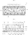
- FIG. 1 is a plan view of a battery module 100 according to the present disclosure
- FIG. 2 is a partially enlarged view of a battery module 100 according to the present disclosure
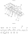
- FIGS. 3A and 3B are a perspective view and a front view of a flexible busbar 120 according to the present disclosure.
- the battery module 100 may include a plurality of battery cells 110, and a plurality of busbars 120 electrically connecting the plurality of battery cells 110.
- a substantially plate-shaped insulating holder 130 may be between the battery cell 110 and the busbar 120.
- end plates 141 and 142 may be at opposite ends of the battery module 100 in a longitudinal direction (e.g., in a first direction), and side plates 151 and 152 may be at opposite ends of the battery module 100 in a width direction.
- output terminals may be connected to the last or outer opposite ends of the busbar 120, or another battery module may be connected thereto.
- the busbar 120 may be electrically connected to a battery monitoring system board.
- a voltage sensor or a current sensor may be connected to the busbar 120, which may be electrically connected to the battery monitoring system board.
- the battery cell 110 may include a rechargeable secondary battery.
- the battery cell 110 may be a prismatic cell, a pouch-type cell, or a cylindrical cell.
- the battery cell 110 may include a positive electrode terminal or a negative electrode terminal.
- the positive electrode terminal and the negative electrode terminal are simply referred to as a terminal 111.
- the plurality of battery cells 110 may be arranged in a line in the first direction, and accordingly, the plurality of terminals 111 may also be arranged in a line in the first direction.
- the busbar 120 may electrically connect the plurality of battery cells 110.
- the busbar 120 may connect a plurality of battery cells 110 in parallel or connect a plurality of battery cells 110 in series.
- the busbar 120 may include, e.g., a large current busbar 121, a stepped busbar 122, and a wave busbar 123.
- the busbar 120 may be a multi-piece busbar including separate pieces coupled together.
- the large current busbar 121 may include a rectangular plate-shaped body 1211 and a protrusion 1212 that protrudes outwardly from a central region of the body 1211.
- the length direction of the large current busbar 121 may be defined as a first direction, and the width direction thereof may be defined as a second direction.
- the protrusion 1212 may protrude in the second direction from the central region.
- a width of the central region of the large current busbar 121 where the current is concentrated may be relatively wide, and thus heat may be rapidly dissipated.
- a voltage sensor may be connected to the protrusion 1212, thereby facilitating installation of the voltage sensor.
- the large current busbar 121 may include, e.g., copper, a copper alloy, aluminium, or an aluminium alloy. In an implementation, the large current busbar 121 may include copper or aluminium. In an implementation, a thickness of the large current busbar may be greater than a thickness of the stepped busbar, and a thickness of the large current busbar may be greater than a thickness of the wave busbar. In an implementation, a thickness of the large current busbar 121 (e.g., in a vertical direction orthogonal to the first and second directions) may range from approximately 1 mm (millimeters) to approximately 10 mm.
- the large current busbar 121 may allow current to flow from the stepped busbar 122 and the wave busbar 123 in a concentrated manner, or may allow current to flow to the stepped busbar 122 and the wave busbar 123 in a divided manner. Accordingly, a relatively large current may flow through the large current busbar 121 compared to the stepped busbar 122 and the wave busbar 123.
- the large current busbar 121 may be coupled to and fixed to a latching protrusion 131 in the insulation holder 130 on the battery cell 110.
- the large current busbar 121 may also be referred to as a first busbar for convenience.
- the stepped busbar 122 may electrically connect the central region of the large current busbar 121 and the plurality of battery cells 110.
- the stepped busbar 122 may include a body region 1221, a (e.g., at least one) leg region 1222, and an inclined region 1223.
- the body region 1221 may extend (e.g., lengthwise) substantially in the first direction.
- the body region 1221 may be laser or ultrasonically welded to the central region of the large current busbar 121.
- a welding region 1224 may be between the body region 1221 of the stepped busbar 122 and the central region of the large current busbar 121.
- approximately two welding regions 1224 may be provided, and may be provided in an approximately circular or ring shape.
- the leg region 1222 may extend from opposite ends of the body region 1221 to be connected to the battery cells 110.
- the leg region 1222 may be laser or ultrasonically welded to the terminal 111 of the battery cell 110.
- a welding region 1225 may be between the leg region 1222 of the stepped busbar 122 and the terminal 111 of the battery cell 110.
- the welding region 1225 may have a substantially horseshoe shape ( ⁇ ).
- the leg region 1222 may extend from the body region 1221 in the second direction (perpendicular to the first direction).
- the leg region 1222 may include a pair of leg regions extending from (e.g., opposite) ends of the body region 1221.
- the two battery cells 110 may be connected in series or in parallel.
- the inclined region 1223 may have a downwardly inclined shape between the body region 1221 and the leg region 1222.
- a height of the inclined region 1223 (e.g., in the vertical direction) may be substantially equal to the thickness of the large current busbar 121.
- the inclined region 1223 may be bent at least 1 to 5 times.
- the stepped busbar 122 may include, e.g., copper, a copper alloy, aluminium, or an aluminium alloy. In an implementation, the stepped busbar 122 may include aluminium. In an implementation, the thickness of the stepped busbar 122 (e.g., in the vertical direction) may range from approximately 0.1 mm to approximately 2 mm. In an implementation, the stepped busbar 122 may also be referred to as a second busbar for convenience.
- the wave busbar 123 may include an inner body region 1231, a first leg region 1232, a first inclined region 1233, an outer body region 1234, a bending region 1235, a second leg region 1236, and a second inclined region 1237.
- a pair of the wave busbars 123 may be at opposite ends of the large current busbar 121, respectively.
- the inner body region 1231 may be laser or ultrasonically welded to the peripheral region of the large current busbar 121. Accordingly, a welding region 1238 may be between the inner body region 1231 of the wave busbar 123 and the peripheral region of the large current busbar 121. In an implementation, the welding region 1238 may be provided in a roughly circular or ring shape.
- the first leg region 1232 may extend from the inner body region 1231 and be welded to the battery cell 110.
- the first leg region 1232 may extend from the inner body region 1231 in the second direction and may be laser or ultrasonically welded to the terminal 111 of the battery cell 110.
- a welding region 1239 may be between the first leg region 1232 of the wave busbar 123 and the terminal 111 of the battery cell 110.
- the welding region 1239 may have, e.g., a substantially horseshoe shape ( ⁇ ).
- the first inclined region 1233 may be inclined downwardly between the inner body region 1231 and the first leg region 1232.
- a height of the first inclined region 1233 may be equal or similar to the thickness of the large current busbar 121.
- the outer body region 1234 may extend from the inner body region 1231. In an implementation, the outer body region 1234 may extend outwardly from the inner body region 1231 in the first direction (perpendicular to the second direction).
- the bending region 1235 may connect the inner body region 1231 and the outer body region 1234.
- the height of the bending region 1235 e.g., a distance from an apex of the bending region 1235 to a region where the bending region connects to the inner body region 1231 or the outer body region 1234 in the vertical direction
- the height of the bending region 1235 may be about 2 to about 5 times the thickness of the bending region 1235 (e.g., in the vertical direction).
- the height of the bending region 1235 may be greater than the thickness of the large current busbar 121 (e.g., in the vertical direction).
- the bending region 1235 may be bent 2 to 5 times (e.g., between the inner body region 1231 and the outer body region 1234).
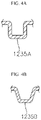
- the bending region 1235 may be bent in a wave shape. In an implementation, the bending region 1235 may be bent in a roughly U shape. In an implementation, the bending region 1235 may have a cross-sectional shape or a lateral shape in which a corner round part or a corner chamfer part is applied to a right angle shape (refer to a bending region 1235A of FIG. 4A ) or a corner round part or a corner chamfer part is applied to a trapezoid shape (refer to a bending region 1235B of FIG. 4B ).
- a battery module 100 may swell as charging and discharging are repeated.
- the position of the terminal 111 of the battery cell 110 could be changed, and, accordingly, stress could be applied to the busbar 120 connected to the terminal 111 of the battery cell 110, and the busbar 120 could be displaced or deformed.
- a relatively large stress could be applied to a portion of the busbar 120 at an outermost portion of the battery module 100, and the busbar 120 could be damaged.
- by providing the wave busbar 123 displacement or deformation of the busbar may be prevented, even when the battery module 100 swells.
- the stress applied to the busbar 120 may be absorbed, and accordingly, displacement and deformation of the busbar may be prevented.
- the second leg region 1236 may extend from the outer body region 1234 to be connected to the battery cell 110.
- the second leg region 1236 may extend in the second direction from the outer body region 1234 to be laser or ultrasonically welded to the terminal 111 of the battery cell 110.
- a welding region 1240 may be between the second leg region 1236 of the wave busbar 123 and the terminal 111 of the battery cell 110.
- the welding region 1240 may have a horseshoe or a roughly circular or ring shape.
- the second inclined region 1237 may be inclined downwardly between the outer body region 1234 and the second leg region 1236.
- the height of the second inclined region 1237 may be equal or similar to the thickness of the large current busbar 121.
- the wave busbar 123 may include, e.g., copper, a copper alloy, aluminium, or an aluminium alloy. In an implementation, the wave busbar 123 may include aluminium. In an implementation, the thickness of the wave busbar 123 may range from approximately 0.1 mm (millimeters) to approximately 2 mm. In some examples, wave busbar 123 may also be referred to as a third busbar for convenience.
- the battery module 100 may include a highly flexible busbar 120, and a plurality of battery cells 110 may be connected in series or in parallel.
- the flexible busbar 120 may not be damaged before the EOL (End Of Life) of the battery module 100 is reached.
- the flexible busbar 120 may help efficiently dissipate heat due to a large area.
- the damage when an impact is applied to the battery module 100 in the flexible busbar 120, the damage may be minimized.
- the flexible busbar 120 may include the wave busbar 123, and if an impact were to be applied along the first direction of the battery module 100, a short circuit caused by contact between the busbars 120 may be prevented.
- the wave busbar 123 may not contact another opposite or adjacent busbar 120.
- the flexible busbar 120 may provide a structure of high-capacity busbar 120 having a low height. Accordingly, a ratio of the space used by the battery cell 110 may be increased.
- One or more embodiments may provide a battery module having a flexible busbar, and having a high-capacity and high-heat-dissipation flexible busbar which allows a large current to flow so as to be applied to a high-capacity battery cell, has excellent heat dissipation performance, and is not broken or damaged even when the battery cell swells.
- a battery module according to an embodiment may provide a flexible busbar that is not broken, displaced, or deformed when the battery cell swells or expands or when it receives an impact from the outside.
- a battery module according to an embodiment may provide a flexible busbar in which little heat is generated even when a large current flows.
- a battery module according to an embodiment may provide a flexible busbar in which little heat is generated even when a large current flows and a voltage sensor or the like is easily installed.
- a battery module according to an embodiment may provide a flexible busbar having small electric resistance.
- a battery module according to an embodiment may provide a flexible busbar that is easily welded to the battery cells.
- a battery module according to an embodiment may provide a flexible busbar that has a small thickness.
- a battery module according to an embodiment may provide a flexible busbar that is capable of easily electrically connecting the plurality of battery cells.
- a battery module according to an embodiment may provide a flexible busbar in which the bending region absorbs stress, and which is not readily broken even when an external shock is applied thereto.
Landscapes
- Chemical & Material Sciences (AREA)
- Chemical Kinetics & Catalysis (AREA)
- Electrochemistry (AREA)
- General Chemical & Material Sciences (AREA)
- Inorganic Chemistry (AREA)
- Engineering & Computer Science (AREA)
- Manufacturing & Machinery (AREA)
- Connection Of Batteries Or Terminals (AREA)
- Battery Mounting, Suspending (AREA)
Applications Claiming Priority (1)
| Application Number | Priority Date | Filing Date | Title |
|---|---|---|---|
| KR1020210051646A KR20220145047A (ko) | 2021-04-21 | 2021-04-21 | 플렉시블 버스바를 갖는 배터리 모듈 |
Publications (2)
| Publication Number | Publication Date |
|---|---|
| EP4080664A2 true EP4080664A2 (de) | 2022-10-26 |
| EP4080664A3 EP4080664A3 (de) | 2023-02-22 |
Family
ID=81327765
Family Applications (1)
| Application Number | Title | Priority Date | Filing Date |
|---|---|---|---|
| EP22166096.2A Pending EP4080664A3 (de) | 2021-04-21 | 2022-03-31 | Batteriemodul mit flexibler stromschiene |
Country Status (4)
| Country | Link |
|---|---|
| US (1) | US12494554B2 (de) |
| EP (1) | EP4080664A3 (de) |
| KR (1) | KR20220145047A (de) |
| CN (1) | CN115224447B (de) |
Families Citing this family (2)
| Publication number | Priority date | Publication date | Assignee | Title |
|---|---|---|---|---|
| CN115764176A (zh) * | 2022-11-30 | 2023-03-07 | 厦门海辰储能科技股份有限公司 | 汇流单元、电池模组及用电设备 |
| KR20250180031A (ko) * | 2024-06-24 | 2025-12-31 | 주식회사 경신전선 | 구리 버스바 |
Family Cites Families (15)
| Publication number | Priority date | Publication date | Assignee | Title |
|---|---|---|---|---|
| KR20150066077A (ko) * | 2013-12-06 | 2015-06-16 | 삼성에스디아이 주식회사 | 배터리 모듈 |
| KR101720618B1 (ko) | 2013-12-17 | 2017-03-28 | 삼성에스디아이 주식회사 | 버스바 홀더를 포함하는 배터리 모듈 |
| US10700335B2 (en) * | 2016-09-07 | 2020-06-30 | Thunder Power New Energy Vehicle Development Company Limited | Battery system housing with internal busbar |
| KR20180039526A (ko) | 2016-10-10 | 2018-04-18 | 한국단자공업 주식회사 | 버스바모듈 및 이를 이용한 배터리모듈용 연결장치 |
| CN109301634B (zh) | 2017-07-24 | 2020-06-19 | 莫仕连接器(成都)有限公司 | 电池连接模块 |
| EP3506383B1 (de) * | 2017-12-28 | 2020-02-12 | Samsung SDI Co., Ltd. | Batteriemodul |
| CN119315223A (zh) | 2018-03-30 | 2025-01-14 | 三洋电机株式会社 | 电池模块、具有该电池模块的车辆 |
| KR102259380B1 (ko) | 2018-04-20 | 2021-06-01 | 주식회사 엘지에너지솔루션 | 버스바를 구비한 배터리 모듈 및 배터리 팩 |
| CN208444901U (zh) | 2018-05-18 | 2019-01-29 | 长城汽车股份有限公司 | 电池模组和具有其的用于车辆的电池包 |
| KR102340419B1 (ko) | 2018-09-21 | 2021-12-15 | 주식회사 엘지에너지솔루션 | 모듈 버스바를 포함하는 배터리 모듈 |
| PL3644408T3 (pl) | 2018-10-26 | 2024-01-03 | Samsung Sdi Co., Ltd. | Moduł baterii |
| US11271272B2 (en) | 2018-10-26 | 2022-03-08 | Samsung Sdi Co., Ltd. | Battery module |
| US20200144579A1 (en) | 2018-11-01 | 2020-05-07 | Ford Global Technologies, Llc | Electrified vehicle with low profile busbar for high current interfaces, and corresponding method |
| JP7025376B2 (ja) | 2019-06-17 | 2022-02-24 | 矢崎総業株式会社 | バスバモジュール |
| CN110931696B (zh) | 2019-11-26 | 2022-04-22 | 中航光电科技股份有限公司 | 一种电池模组及其线束板组件 |
-
2021
- 2021-04-21 KR KR1020210051646A patent/KR20220145047A/ko active Pending
-
2022
- 2022-02-18 US US17/675,148 patent/US12494554B2/en active Active
- 2022-03-22 CN CN202210286817.4A patent/CN115224447B/zh active Active
- 2022-03-31 EP EP22166096.2A patent/EP4080664A3/de active Pending
Also Published As
| Publication number | Publication date |
|---|---|
| KR20220145047A (ko) | 2022-10-28 |
| CN115224447A (zh) | 2022-10-21 |
| EP4080664A3 (de) | 2023-02-22 |
| US20220344784A1 (en) | 2022-10-27 |
| US12494554B2 (en) | 2025-12-09 |
| CN115224447B (zh) | 2025-04-08 |
Similar Documents
| Publication | Publication Date | Title |
|---|---|---|
| US11916244B2 (en) | Battery module including partition member | |
| CN106663773B (zh) | 电极构件及集电板、电池组 | |
| US9203065B2 (en) | Battery module | |
| CN101485010B (zh) | 用于二次电池的安全配套元件 | |
| US10439179B2 (en) | Rechargeable battery module including welding bushes | |
| US8889292B2 (en) | Rechargeable battery | |
| US9178206B2 (en) | Battery module | |
| KR100880389B1 (ko) | 이차전지 모듈의 제조방법 | |
| US7993774B2 (en) | Conductive plate and secondary battery pack using conductive plate | |
| US20180040918A1 (en) | Rechargeable battery having current collector | |
| US20130078505A1 (en) | Rechargeable battery | |
| CN102005597A (zh) | 可再充电电池 | |
| KR20160087220A (ko) | 이차전지 및 이차전지 배열 | |
| US11942660B2 (en) | Battery pack | |
| ES3056830T3 (en) | Battery module in which connection between electrode lead and voltage sensing member is simplified, and battery pack including the same | |
| EP4080664A2 (de) | Batteriemodul mit flexibler stromschiene | |
| KR20200054755A (ko) | 모듈 하우징을 포함한 배터리 모듈 | |
| KR20150046533A (ko) | 파우치형 이차 전지 및 이를 포함하는 배터리 팩 | |
| EP3367463A2 (de) | Batteriemodul sowie batteriepack und fahrzeug damit | |
| US9997809B2 (en) | Battery module | |
| US10014495B2 (en) | Rechargeable battery | |
| US20160043379A1 (en) | Rechargeable battery having short-circuit protrusion | |
| CN113508492B (zh) | 电化学电池模块 | |
| EP3582292B1 (de) | Batteriemodul | |
| KR101826862B1 (ko) | 보호 모듈을 포함하는 전지팩 |
Legal Events
| Date | Code | Title | Description |
|---|---|---|---|
| PUAI | Public reference made under article 153(3) epc to a published international application that has entered the european phase |
Free format text: ORIGINAL CODE: 0009012 |
|
| STAA | Information on the status of an ep patent application or granted ep patent |
Free format text: STATUS: REQUEST FOR EXAMINATION WAS MADE |
|
| 17P | Request for examination filed |
Effective date: 20220331 |
|
| AK | Designated contracting states |
Kind code of ref document: A2 Designated state(s): AL AT BE BG CH CY CZ DE DK EE ES FI FR GB GR HR HU IE IS IT LI LT LU LV MC MK MT NL NO PL PT RO RS SE SI SK SM TR |
|
| PUAL | Search report despatched |
Free format text: ORIGINAL CODE: 0009013 |
|
| AK | Designated contracting states |
Kind code of ref document: A3 Designated state(s): AL AT BE BG CH CY CZ DE DK EE ES FI FR GB GR HR HU IE IS IT LI LT LU LV MC MK MT NL NO PL PT RO RS SE SI SK SM TR |
|
| RIC1 | Information provided on ipc code assigned before grant |
Ipc: H01M 50/522 20210101ALI20230119BHEP Ipc: H01M 50/516 20210101ALI20230119BHEP Ipc: H01M 50/507 20210101ALI20230119BHEP Ipc: H01M 50/503 20210101AFI20230119BHEP |
|
| STAA | Information on the status of an ep patent application or granted ep patent |
Free format text: STATUS: EXAMINATION IS IN PROGRESS |
|
| 17Q | First examination report despatched |
Effective date: 20260220 |