EP4080668B1 - Élément de batterie, batterie et dispositif électrique - Google Patents
Élément de batterie, batterie et dispositif électrique Download PDFInfo
- Publication number
- EP4080668B1 EP4080668B1 EP20952033.7A EP20952033A EP4080668B1 EP 4080668 B1 EP4080668 B1 EP 4080668B1 EP 20952033 A EP20952033 A EP 20952033A EP 4080668 B1 EP4080668 B1 EP 4080668B1
- Authority
- EP
- European Patent Office
- Prior art keywords
- tab
- size
- body portion
- adapting
- battery cell
- Prior art date
- Legal status (The legal status is an assumption and is not a legal conclusion. Google has not performed a legal analysis and makes no representation as to the accuracy of the status listed.)
- Active
Links
Images



Classifications
-
- H—ELECTRICITY
- H01—ELECTRIC ELEMENTS
- H01M—PROCESSES OR MEANS, e.g. BATTERIES, FOR THE DIRECT CONVERSION OF CHEMICAL ENERGY INTO ELECTRICAL ENERGY
- H01M50/00—Constructional details or processes of manufacture of the non-active parts of electrochemical cells other than fuel cells, e.g. hybrid cells
- H01M50/20—Mountings; Secondary casings or frames; Racks, modules or packs; Suspension devices; Shock absorbers; Transport or carrying devices; Holders
- H01M50/204—Racks, modules or packs for multiple batteries or multiple cells
- H01M50/207—Racks, modules or packs for multiple batteries or multiple cells characterised by their shape
- H01M50/209—Racks, modules or packs for multiple batteries or multiple cells characterised by their shape adapted for prismatic or rectangular cells
-
- H—ELECTRICITY
- H01—ELECTRIC ELEMENTS
- H01M—PROCESSES OR MEANS, e.g. BATTERIES, FOR THE DIRECT CONVERSION OF CHEMICAL ENERGY INTO ELECTRICAL ENERGY
- H01M50/00—Constructional details or processes of manufacture of the non-active parts of electrochemical cells other than fuel cells, e.g. hybrid cells
- H01M50/50—Current conducting connections for cells or batteries
- H01M50/531—Electrode connections inside a battery casing
- H01M50/54—Connection of several leads or tabs of plate-like electrode stacks, e.g. electrode pole straps or bridges
-
- H—ELECTRICITY
- H01—ELECTRIC ELEMENTS
- H01M—PROCESSES OR MEANS, e.g. BATTERIES, FOR THE DIRECT CONVERSION OF CHEMICAL ENERGY INTO ELECTRICAL ENERGY
- H01M50/00—Constructional details or processes of manufacture of the non-active parts of electrochemical cells other than fuel cells, e.g. hybrid cells
- H01M50/10—Primary casings; Jackets or wrappings
- H01M50/102—Primary casings; Jackets or wrappings characterised by their shape or physical structure
- H01M50/103—Primary casings; Jackets or wrappings characterised by their shape or physical structure prismatic or rectangular
-
- H—ELECTRICITY
- H01—ELECTRIC ELEMENTS
- H01M—PROCESSES OR MEANS, e.g. BATTERIES, FOR THE DIRECT CONVERSION OF CHEMICAL ENERGY INTO ELECTRICAL ENERGY
- H01M50/00—Constructional details or processes of manufacture of the non-active parts of electrochemical cells other than fuel cells, e.g. hybrid cells
- H01M50/10—Primary casings; Jackets or wrappings
- H01M50/147—Lids or covers
- H01M50/148—Lids or covers characterised by their shape
- H01M50/15—Lids or covers characterised by their shape for prismatic or rectangular cells
-
- H—ELECTRICITY
- H01—ELECTRIC ELEMENTS
- H01M—PROCESSES OR MEANS, e.g. BATTERIES, FOR THE DIRECT CONVERSION OF CHEMICAL ENERGY INTO ELECTRICAL ENERGY
- H01M50/00—Constructional details or processes of manufacture of the non-active parts of electrochemical cells other than fuel cells, e.g. hybrid cells
- H01M50/20—Mountings; Secondary casings or frames; Racks, modules or packs; Suspension devices; Shock absorbers; Transport or carrying devices; Holders
- H01M50/249—Mountings; Secondary casings or frames; Racks, modules or packs; Suspension devices; Shock absorbers; Transport or carrying devices; Holders specially adapted for aircraft or vehicles, e.g. cars or trains
-
- H—ELECTRICITY
- H01—ELECTRIC ELEMENTS
- H01M—PROCESSES OR MEANS, e.g. BATTERIES, FOR THE DIRECT CONVERSION OF CHEMICAL ENERGY INTO ELECTRICAL ENERGY
- H01M50/00—Constructional details or processes of manufacture of the non-active parts of electrochemical cells other than fuel cells, e.g. hybrid cells
- H01M50/50—Current conducting connections for cells or batteries
- H01M50/528—Fixed electrical connections, i.e. not intended for disconnection
-
- H—ELECTRICITY
- H01—ELECTRIC ELEMENTS
- H01M—PROCESSES OR MEANS, e.g. BATTERIES, FOR THE DIRECT CONVERSION OF CHEMICAL ENERGY INTO ELECTRICAL ENERGY
- H01M50/00—Constructional details or processes of manufacture of the non-active parts of electrochemical cells other than fuel cells, e.g. hybrid cells
- H01M50/50—Current conducting connections for cells or batteries
- H01M50/531—Electrode connections inside a battery casing
- H01M50/533—Electrode connections inside a battery casing characterised by the shape of the leads or tabs
-
- H—ELECTRICITY
- H01—ELECTRIC ELEMENTS
- H01M—PROCESSES OR MEANS, e.g. BATTERIES, FOR THE DIRECT CONVERSION OF CHEMICAL ENERGY INTO ELECTRICAL ENERGY
- H01M2220/00—Batteries for particular applications
- H01M2220/20—Batteries in motive systems, e.g. vehicle, ship, plane
-
- Y—GENERAL TAGGING OF NEW TECHNOLOGICAL DEVELOPMENTS; GENERAL TAGGING OF CROSS-SECTIONAL TECHNOLOGIES SPANNING OVER SEVERAL SECTIONS OF THE IPC; TECHNICAL SUBJECTS COVERED BY FORMER USPC CROSS-REFERENCE ART COLLECTIONS [XRACs] AND DIGESTS
- Y02—TECHNOLOGIES OR APPLICATIONS FOR MITIGATION OR ADAPTATION AGAINST CLIMATE CHANGE
- Y02E—REDUCTION OF GREENHOUSE GAS [GHG] EMISSIONS, RELATED TO ENERGY GENERATION, TRANSMISSION OR DISTRIBUTION
- Y02E60/00—Enabling technologies; Technologies with a potential or indirect contribution to GHG emissions mitigation
- Y02E60/10—Energy storage using batteries
Definitions
- This application relates to the field of battery technologies, and in particular, to a battery cell, a battery, and an electric apparatus.
- a battery includes a plurality of battery cells connected in series or parallel, so as to achieve high capacity or power.
- An electrode assembly of the battery cell includes a body portion and a tab.
- the body portion is configured to generate or store electrical energy.
- the tab is configured to electrically connect the body portion and an external mechanical part.
- US 2006/0040176 A1 disclose a prismatic battery cell housed in a battery casing and including a first adapting component to connect a first electrode terminal and a first tab. Comparable battery cells are known from any of US 2019/020018 A1 , EP 2 404 338 B1 and EP 3 933 951 A1 .
- This application provides a battery cell, a battery, and an electric apparatus, to resolve a technical problem of severe heat generation by a tab.
- the battery cell includes: an electrode assembly, including a body portion and a first tab, where a first size L1 of the body portion in a length direction thereof is greater than a second size L2 of the body portion in a width direction thereof; the first tab is located on at least one end of the body portion in the width direction; the first tab has a third size L3 in the length direction; and the first size L1, the second size L2, and the third size L3 satisfy 0.5L2 ⁇ L3 ⁇ L1.
- the battery cell includes an electrode assembly.
- the electrode assembly includes a body portion and a first tab.
- the first tab is located on at least one end of the body portion in the width direction; Because the first size L1 of the body portion in the length direction is greater than the second size L2 of the body portion in the width direction, the size of the first tab disposed on an end surface of the body portion corresponding to the length direction is no longer restricted by the second size L2 of the body portion in the width direction, so that the third size L3 of the first tab in the length direction can be set greater than or equal to a half of the second size L2 of the body portion in the width direction. This helps improve current flow capacity of the first tab, to reduce the possibility of severe heat generation by the first tab due to insufficient current flow capacity.
- the first size L1, the second size L2, and the third size L3 satisfy L2 ⁇ L3 ⁇ L1.
- the third size L3 of the first tab in the length direction may be greater than or equal to the second size L2 of the body portion in the width direction, thereby helping further improve the current flow capacity of the first tab.
- the first size L1 and the second size L2 satisfy that a ratio of L1 to L2 ranges from 4 to 20.
- the battery cell further includes: a housing, where an electrode assembly is located inside the housing; a first end cap, located on a side of the electrode assembly in the length direction and configured to close a first opening of the housing; a first electrode terminal, disposed on the first end cap; and a first adapting component, configured to connect the first electrode terminal and the first tab.
- the electrode assembly further includes a second tab with a polarity opposite to that of the first tab, the first tab and the second tab are disposed on a same end of the body portion in the width direction, and the first tab and the second tab are spaced apart in the length direction.
- the first size L1, the second size L2, and the third size L3 satisfy 0.5L2 ⁇ L3 ⁇ 0.5L1.
- the second tab has a fourth size L4 in the length direction, and the first size L1, the second size L2, and the fourth size L4 satisfy 0.5L22:L4 ⁇ 0.5L1. In this way, in the length direction, the first tab and the second tab are not in contact with each other, ensuring that the first tab and the second tab are not short-circuited by each other while having sufficient current flow capacity.
- the first adapting component includes a first adapting plate and a second adapting plate, the first adapting plate is configured to be connected to the first electrode terminal, and the second adapting plate is configured to be connected to the first tab.
- the electrode assembly further includes a second tab with a polarity opposite to that of the first tab, the first tab includes two first sub-tabs, the two first sub-tabs are respectively located on two ends of the body portion in the width direction, the second tab includes two second sub-tabs, and the two second sub-tabs are respectively located on two ends of the body portion in the width direction.
- the first sub-tab and the second sub-tab on a same end of the body portion are spaced apart in the length direction.
- the first tab is divided into two first sub-tabs and the second tab is divided into two second sub-tabs. This manner can effectively reduce the number of tabs disposed on one end of the body portion, thereby effectively lowering the possible difficulty in connecting the first tab and the second tab respectively to the first adapting component and the second adapting component caused by a great thickness resulted from a large number of the first tabs or the second tabs disposed on one end of the body portion.
- This manner can also effectively improve heat dissipation efficiency of the first tab and the second tab, reducing the possibility of severe heat generation by the first tab or the second tab caused by poor heat dissipation resulted from a large number of the first tabs or the second tabs.
- the first adapting component includes a first adapting plate and two second adapting plates, the first adapting plate is configured to be connected to the first electrode terminal, and the two second adapting plates are configured to be respectively connected to the two first sub-tabs.
- the two first sub-tabs and the two second sub-tabs are disposed in a staggered manner in the width direction.
- the second adapting plate includes a body part and a bending part, the body part is configured to be connected to the first adapting plate, and the bending part is configured to be connected to the first tab.
- the first tab and the bending part may be connected and fastened, and then the bending part may be bent towards the body part to a predetermined position. This can lower the possible difficulty in connecting the first tab and the second adapting plate due to the second adapting plate being close to the body portion, making it easier to connect the first tab and the second adapting plate.
- the battery cell further includes: a second end cap, located on the other side of the electrode assembly in the length direction and configured to close a second opening of the housing; a second electrode terminal, disposed on the second end cap; and a second adapting component, configured to connect the second electrode terminal and the second tab.
- the battery cell in this embodiment of this application includes a housing and an electrode assembly.
- the electrode assembly is disposed inside the housing.
- a surface of the body portion of the electrode assembly parallel to the width direction faces towards a first opening of the housing.
- An end surface of the body portion parallel to the length direction faces towards a side wall of the housing.
- the first tab is disposed on the end surface of the body portion.
- the first tab is located between the end surface of the body portion and the housing. Therefore, the first tab is disposed on the end surface and the first size L1, the second size L2, and the third size L3 satisfy 0.5L2 ⁇ L3 ⁇ L1, so that the size of the first tab is no longer restricted by the second size L2 of the body portion in the width direction.
- the overall length of the electrode assembly is no longer restricted by the current flow capacity of the first tab, so that an electrode assembly with a greater length but the same width can be processed and produced. This effectively increases energy density of the electrode assembly, and helps increase the energy density of the battery cell without increasing overall space occupancy of the battery cell in the width direction.
- An embodiment of this application further provides a battery, including the battery cell according to the foregoing embodiments.
- An embodiment of this application further provides an electric apparatus, including the battery cell according to the foregoing embodiments, where the battery cell is configured to supply electrical energy.
- the applicants have studied and analyzed a battery cell after discovering a problem of severe heat generation by a tab.
- the applicants have found that because a requirement for energy density of a battery cell is getting higher and space occupancy of the battery cell itself needs to meet requirements, the battery cell is made into a long-strip flat structure, so that the body portion of the electrode assembly is longer and in a long-strip flat structure.
- the tab extends out from the body portion in a width direction.
- the tab extending out from the end surface of the body portion in the width direction has a problem of insufficient current flow capacity, failing to satisfy a demand for fast charging.
- the applicants improved the structure of the tab, for example, increasing the size of the tab.
- the tab still has the problem of insufficient current flow capacity after the size of the tab is increased in the width direction.
- An embodiment of this application provides an electric apparatus using a battery 10 as a power supply.
- the electric apparatus may be, but is not limited to, a vehicle, a ship, or a flight vehicle.
- a vehicle 1 may be an oil-fueled vehicle, a gas-powered vehicle, or a new energy vehicle.
- the new energy vehicle may be a battery electric vehicle, a hybrid electric vehicle, or an extended-range electric vehicle.
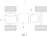
- the vehicle 1 may include a motor 1a, a controller 1b, and a battery 10.
- the controller 1b is configured to control the battery 10 to supply power to the motor 1a.
- the motor 1a is connected to wheels through a driving mechanism to drive the vehicle 1 forward.
- the battery 10 may be used as a driving power supply for the vehicle 1 to totally or partially replace fossil fuel or natural gas to provide driving power for the vehicle 1.
- a battery 10 may be disposed at the bottom, the front, or the rear of the vehicle 1.
- the battery 10 may be configured to supply power for the vehicle 1.
- the battery 10 may be used as an operational power supply for the vehicle 1 for a circuit system of the vehicle 1.
- the battery 10 may be configured to supply power to meet the start, navigation, and driving requirements of the vehicle 1.
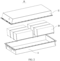
- the battery 10 may include more than two battery modules 20.
- the battery 10 further includes a box body.
- the battery module 20 is disposed inside the box body.
- the more than two battery modules 20 are arranged inside the box body.
- the box body is not limited to a specific type.
- the box body may be frame-shaped, disk-shaped, or box-shaped.
- the box body includes a first shell 11 configured to accommodate the battery modules 20 and a second shell 12 engaged to the first shell 11.
- the first shell 11 is engaged to the second shell 12 to form an accommodating portion for accommodating the battery modules 20.
- the battery module 20 may include one or more battery cells.
- a plurality of battery cells 30 may first be connected in series, parallel, or series and parallel to constitute a battery module, and then a plurality of battery modules 20 may be connected in series, parallel, or series and parallel to constitute a battery.
- the battery may include a plurality of battery cells 30, where the plurality of battery cells 30 may be connected in series, parallel, or series and parallel, and being connected in series and parallel means a combination of series and parallel connections.
- the plurality of battery cells 30 may be directly disposed inside the box body.
- the plurality of battery cells may directly constitute a battery, or may first constitute a battery module, and then a plurality of battery modules constitute a battery.
- the battery cell 30 includes a lithium-ion secondary battery, a lithium-ion primary battery, a lithium-sulfur battery, a sodium-lithium-ion battery, or a magnesium-ion battery, but is not limited thereto.
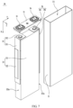
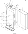
- the battery cell 30 in an embodiment of this application includes a housing 31 and an electrode assembly 32 disposed inside the housing 31.
- the housing 31 in this embodiment of this application is rectangular or of other shapes.
- the housing 31 has an internal space for accommodating the electrode assembly 32 and an electrolyte and a first opening 311 communicating with the internal space.
- the housing 31 may be made of materials such as aluminum, aluminum alloy, or plastics.
- the electrode assembly 32 in this embodiment of this application may be formed through stacking or winding of a first electrode plate, a second electrode plate, and a separator located between the first electrode plate and the second electrode plate, where the separator is an insulator sandwiched between the first electrode plate and the second electrode plate.
- the first electrode plate and the second electrode plate each include a coated area and an uncoated area.
- An active substance is applied to the coated area of the first electrode plate and the coated area of the second electrode plate. On the coated area, the active substance is applied on a current collector formed by metal sheets, while on the uncoated area, no active substance is applied.
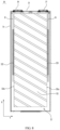
- the electrode assembly 32 includes a body portion 321 and a first tab 322. After stacking, the coated area of the first electrode plate, the coated area of the second electrode plate, and the separator are stacked to form the body portion 321.
- the uncoated areas of the first electrode plate are stacked to form the first tab 322.
- the uncoated areas of the second electrode plate are stacked to form a second tab 323.
- the first tab 322 and the second tab 323 have opposite polarities. For example, when the first tab 322 is a positive tab, the second tab 323 is a negative tab. When the first tab 322 is a negative tab, the second tab 323 is a positive tab.
- the body portion 321 has a predetermined length, width, and thickness.
- the length is a size of the body portion 321 in a length direction X thereof
- the width is a size of the body portion 321 in a width direction Y thereof
- the thickness is a size of the body portion 321 in a thickness direction Z thereof.
- a first size of the body portion 321 in the length direction X thereof is L1
- a second size of the body portion 321 in the width direction Y thereof is L2.
- the length direction X, the width direction Y, and the thickness direction Z are perpendicular to each other.
- the first size L1 of the body portion 321 is greater than the second size L2 of the body portion 321.
- the body portion 321 has two ends disposed opposite each other in the width direction Y thereof, and each end has an end surface 321a. After the electrode assembly 32 is disposed inside the housing 31, an end surface 321a of the body portion 321 faces towards the housing 31.
- the first tab 322 extends out from an end surface 321a of the body portion 321.
- a third size of the first tab 322 in the length direction X is L3.
- the first size L1, the second size L2, and the third size L3 satisfy 0.5L2 ⁇ L3 ⁇ L1.
- the third size L3 may be 0.5L2, 0.6L2, 0.7L2, 0.8L2, 0.9L2, L2, 0.1L1, 0.2L1, 0.3L1, 0.4L1, 0.5L1, 0.6L1, 0.7L1, 0.8L1, 0.9L1, L1, or the like.
- the battery cell 30 in this embodiment of this application includes a housing 31 and an electrode assembly 32.
- the electrode assembly 32 is disposed inside the housing 31.
- a surface of the body portion 321 of the electrode assembly 32 parallel to the width direction Y faces towards a first opening 311 of the housing 31.
- An end surface 321a of the body portion 321 parallel to the length direction X faces towards a side wall of the housing 31.
- the first tab 322 is disposed on the end surface 321a of the body portion 321.
- the first tab 322 is located between the end surface 321a of the body portion 321 and the housing 31.
- the first tab 322 is disposed on the end surface 321a, and the first size L1, the second size L2, and the third size L3 satisfy 0.5L2 ⁇ L3 ⁇ L1, so that the size of the first tab 322 is no longer restricted by the second size L2 of the body portion 321 in the width direction Y.
- This helps improve the current flow capacity of the first tab 322, to reduce the possibility of severe heat generation by the first tab 322 due to insufficient current flow capacity.
- an overall length of the electrode assembly 32 is no longer restricted by the current flow capacity of the first tab 322, so that an electrode assembly 32 with a greater length but the same width can be processed and produced. This effectively increases energy density of the electrode assembly 32, and also helps increase the energy density of the battery cell 30 without increasing overall space occupancy of the battery cell 30 in the width direction Y.
- the width direction Y of the battery cell 30 is the same as a height direction of the vehicle 1. Restricted by space of the vehicle 1 in the height direction, width of the battery cell 30 is also strictly restricted. As a result, when capacity of the battery cell 30 needs to be increased, the width of the battery cell 30 cannot be increased unlimitedly, but length of the battery cell 30 can be increased.
- the first size L1 of the body portion 321 in the length direction X and the second size L2 of the body portion 321 satisfy that a ratio of L1 to L2 ranges from 4 to 20.
- a value of the first size L1 ranges from 35 centimeters (cm) to 100 centimeters (cm).
- the first size L1, the second size L2, and the third size L3 satisfy L2 ⁇ L3 ⁇ L1.
- the third size L3 may be L2, 2L2, 3L2, 4L2, 5L2, or the like.
- the third size L3 of the first tab 322 in the length direction X may be greater than or equal to the second size L2 of the body portion 321 in the width direction Y, thereby helping further improve the current flow capacity of the first tab 322.
- the battery cell 30 in this embodiment of this application further includes a first end cap 33, a first electrode terminal 34, and a first adapting component 35.
- the first end cap 33 is connected to the housing 31 and closes a first opening 311 of the housing 31.
- the first end cap 33 may be connected to the housing 31 by welding.
- the first end cap 33 is located on a side of the electrode assembly 32 in the length direction X. In the length direction X, the first end cap 33 is disposed opposite a surface of the body portion 321 parallel to the width direction Y.
- the first electrode terminal 34 is disposed on the first end cap 33.
- the first electrode terminal 34 may be round-shaped or square-shaped, which is not limited herein.
- the first electrode terminal 34 is electrically connected to the first tab 322 of the electrode assembly 32 through the first adapting component 35.
- the third size L3 of the first tab 322 in the length direction X is smaller than the first size L1 of the body portion 321 in the length direction X
- the first tab 322 is disposed in an area of the body portion 321 closer to the first end cap 33, thereby helping shorten connection distance to the first adapting component 35.
- the first adapting component 35 includes a first adapting plate 351 and a second adapting plate 352.
- the first adapting plate 351 and the second adapting plate 352 form an L shape, and the first adapting plate 351 is configured to be connected to the first electrode terminal 34.
- the second adapting plate 352 is configured to be connected to the first tab 322. In an example, the second adapting plate 352 is connected to the first tab 322 by welding.
- the first tab 322 and the second tab 323 are respectively disposed on two ends of the body portion 321 in the width direction Y.
- the first tab 322 and the second tab 323 are separately disposed, so that the first tab 322 and the second tab 323 each can make full use of an area of an end surface 321a to select a size in the length direction X, thereby preventing the first tab 322 and the second tab 323 from interfering with each other in the length direction X.
- the second tab 323 has a fourth size L4 in the length direction X.
- the first size L1, the second size L2, and the fourth size L4 satisfy 0.5L2 ⁇ L4 ⁇ L1.
- the fourth size L4 may be 0.5L2, 0.6L2, 0.7L2, 0.8L2, 0.9L2, L2, 0.1L1, 0.2L1, 0.3L1, 0.4L1, 0.5L1, 0.6L1, 0.7L1, 0.8L1, 0.9L1, L1, or the like.
- the second tab 323 is disposed on an end surface 321a of the body portion 321.
- the second tab 323 is located between the end surface 321a of the body portion 321 and the housing 31. Therefore, the second tab 323 is disposed on the end surface 321a, and the first size L1, the second size L2, and the fourth size L4 satisfy 0.5L2 ⁇ L4 ⁇ L1, so that the size of the second tab 323 is no longer restricted by the second size L2 of the body portion 321 in the width direction Y. This helps improve the current flow capacity of the second tab 323, to reduce the possibility of severe heat generation by the second tab 323 due to insufficient current flow capacity.
- an overall length of the electrode assembly 32 is no longer restricted by the current flow capacity of the second tab 323, so that an electrode assembly 32 with a greater length but the same width can be processed and produced.
- the third size L3 of the first tab 322 in the length direction X is equal to the fourth size L4 of the second tab 323 in the length direction X.
- the battery cell 30 further includes a second end cap 36, a second electrode terminal 37, and a second adapting component 38.
- the housing 31 further includes a second opening 312. In the length direction X, the first opening 311 is disposed opposite the second opening 312.
- the second end cap 36 is connected to the housing 31 and closes the second opening 312 of the housing 31.
- the second end cap 36 may be connected to the housing 31 by welding.
- the second end cap 36 is located on the other side of the electrode assembly 32 in the length direction X. In the length direction X, the first end cap 33 is disposed opposite the second end cap 36.
- the second end cap 36 is disposed opposite a surface of the body portion 321 parallel to the width direction Y.
- the second electrode terminal 37 is disposed on the second end cap 36.
- the second electrode terminal 37 may be round-shaped or square-shaped, which is not limited herein.
- the second electrode terminal 37 is connected to the second tab 323 of the electrode assembly 32 through the second adapting component 38.
- the fourth size L4 of the second tab 323 in the length direction X is smaller than the first size L1 of the body portion 321 in the length direction X
- the second tab 323 is disposed on an area of the body portion 321 closer to the second end cap 36, thereby helping shorten connection distance to the second adapting component 38.
- the second adapting component 38 includes a third adapting plate 381 and a fourth adapting plate 382.
- the third adapting plate 381 is configured to be connected to the second electrode terminal 37.
- the fourth adapting plate 382 is configured to be connected to the second tab 323.
- the first adapting component 35 and the second adapting component 38 have the same structure, meaning that the first adapting plate 351 and the third adapting plate 381 have the same structure and the second adapting plate 352 and the fourth adapting plate 382 have the same structure.
- the fourth adapting plate 382 is connected to the second tab 323 by welding.
- the second adapting plate 352 of the first adapting component 35 includes a body part 3521 and a bending part 3522.
- the body part 3521 is configured to be connected to the first adapting plate 351.
- the bending part 3522 is configured to be connected to the first tab 322. Before the bending part 3522 is bent, the first tab 322 and the bending part 3522 may be connected and fastened, and then the bending part 3522 may be bent towards the body part 3521 to a predetermined position. In this way, space occupied by the second adapting plate 352 in the width direction Y can be reduced, and energy density is increased.
- the housing 31 has a first opening 311.
- the electrode assembly 32 is disposed inside the housing 31.
- the first end cap 33 is connected to the housing 31 and closes the first opening 311.
- the first electrode terminal 34 and the second electrode terminal 37 are both disposed on the first end cap 33.
- the first tab 322 and the second tab 323 are respectively disposed on two ends of the body portion 321 in the width direction Y.
- the first adapting component 35 and the second adapting component 38 are connected to the first electrode terminal 34 and the second electrode terminal 37, respectively.
- the first tab 322 and the second tab 323 are disposed on a same end of the body portion 321 in the width direction Y, meaning that the first tab 322 and the second tab 323 are disposed on a same end surface 321a.
- the first tab 322 and the second tab 323 are spaced apart in the length direction X.
- the first tab 322 and the second tab 323 are disposed in a staggered manner, meaning that in the length direction X, projections of the first tab 322 and the second tab 323 do not overlap.
- the first size L1 of the body portion 321 in the length direction X, the second size L2 of the body portion 321 in the width direction Y, and the third size L3 of the first tab 322 in the length direction X satisfy 0.5L2 ⁇ L3 ⁇ 0.5L1
- the first size L1 of the body portion 321 in the length direction X, the second size L2 of the body portion 321 in the width direction Y, and the fourth size L4 of the second tab 323 in the length direction X satisfy 0.5L2 ⁇ L4 ⁇ 0.5L1.
- the first tab 322 and the second tab 323 are not in contact with each other, ensuring that the first tab 322 and the second tab 323 are not short-circuited by each other while having sufficient current flow capacity.
- the first tab 322 and the second tab 323 are connected to the first adapting component 35 and the second adapting component 38 respectively, the first tab 322 and the second tab 323 are bent in opposite directions, thereby helping reduce the possibility of short circuit caused by contact between the first tab 322 and the second tab 323.
- the first tab 322 includes two first sub-tabs 3221.
- the two first sub-tabs 3221 are respectively located on two ends of the body portion 321 in the width direction Y.
- the two first sub-tabs 3221 respectively extend out from the two end surfaces 321a of the body portion 321.
- the second tab 323 includes two second sub-tabs 3231.
- the two second sub-tabs 3231 are respectively located on two ends of the body portion 321 in the width direction Y.
- the two second sub-tabs 3231 respectively extends out from the two end surfaces 321a of the body portion 321.
- the electrode assembly 32 has a high capacity, a current flow requirement can be met only when there are a large number of the first tabs 322 and the second tabs 323.
- the first tab 322 is divided into two first sub-tabs 3221 and the second tab 323 is divided into two second sub-tabs 3231.
- This manner can effectively reduce the number of tabs disposed on one end of the body portion 321, thereby effectively lowering the possible difficulty in connecting the first tab 322 and the second tab 323 respectively to the first adapting component 35 and the second adapting component 38 caused by a great thickness resulted from a large number of the first tabs 322 or the second tabs 323 disposed on one end of the body portion 321.
- This manner can also effectively improve heat dissipation efficiency of the first tab 322 and the second tab 323, reducing the possibility of severe heat generation by the first tab 322 or the second tab 323 caused by poor heat dissipation resulted from a large number of the first tabs 322 or the second tabs 323.
- the first sub-tab 3221 and the second sub-tab 3231 on a same side of the body portion 321 are spaced apart in the length direction X. In this way, in the length direction X, the first sub-tab 3221 and the second sub-tab 3231 are not in contact with each other, ensuring that the first sub-tab 3221 and the second sub-tab 3231 are not short-circuited by each other while having sufficient current flow capacity.
- the first sub-tab 3221 and the second sub-tab 3231 are connected to the first adapting component 35 and the second adapting component 38 respectively, the first sub-tab 3221 and the second sub-tab 3231 are bent in opposite directions, thereby helping minimize an overlap between the first sub-tab 3221 and the second sub-tab 3231 in the length direction X, and further reducing the possibility of short circuit resulted from contact between the first sub-tab 3221 and the second sub-tab 3231.
- the two first sub-tabs 3221 are disposed in a staggered manner in the width direction Y, meaning that in the width direction Y, orthographic projections of the two first sub-tabs 3221 do not overlap.
- the two second sub-tabs 3231 are disposed in a staggered manner in the width direction Y, meaning that in the width direction Y, projections of the two second sub-tabs 3231 do not overlap.
- a first electrode plate, a second electrode plate, and a separator are stacked to form an electrode assembly 32. A half of the total first electrode plates form one first sub-tab 3221, and the other half of the total first electrode plates form another first sub-tab 3221.
- first electrode plates there are totally 100 first electrode plates, of which 50 first electrode plates form one first sub-tab 3221, and the other 50 first electrode plates form another first sub-tab 3221. Further, the first sub-tab 3221 is formed by adjacent first electrode plates. Likewise, a half of the total second electrode plates form one second sub-tab 3231, and the other half of the total second electrode plates form another second sub-tab 3231. For example, there are totally 100 second electrode plates, of which 50 second electrode plates form one second sub-tab 3231, and the other 50 second electrode plates form another second sub-tab 3231. Further, the second sub-tab 3231 is formed by adjacent second electrode plates.
- the first adapting component 35 includes a first adapting plate 351 and two second adapting plates 352.
- the first adapting plate 351 is configured to be connected to the first electrode terminal 34.
- the two second adapting plates 352 are configured to be respectively connected to the two first sub-tabs 3221.
- the two second adapting plates 352 are located on a same side of the first adapting plate 351, making the first adapting component 35 a U-shaped structure.
- the first adapting plate 351 and the two second adapting plates 352 are an integrally formed structure.
- the second adapting component 38 includes a third adapting plate 381 and two fourth adapting plates 382.
- the third adapting plate 381 is configured to be connected to the second electrode terminal 37.
- the two fourth adapting plates 382 are configured to be respectively connected to the two second sub-tabs 3231.
- the two fourth adapting plates 382 are located on a same side of the third adapting plate 381, making the second adapting component 38 a U-shaped structure.
- the third adapting plate 381 and the two fourth adapting plates 382 are an integrally formed structure.
- the battery cell 30 in this embodiment of this application includes a housing 31 and an electrode assembly 32.
- the electrode assembly 32 includes a body portion 321 and a first tab 322.
- the body portion 321 has predetermined length, width, and thickness. The length of the body portion 321 is greater than the width, and the width is greater than the thickness.
- the body portion 321 is opposite an opening of the housing 31 in a width direction Y.
- the body portion 321 has two opposite end surfaces 321a in the width direction Y thereof.
- the end surface 321a is parallel to the body portion 321 in a length direction X.
- the end surface 321a of the body portion 321 faces towards a side wall of the housing 31.
- the first tab 322 extends out from the end surface 321a. Therefore, the first tab 322 is disposed on the end surface 321a, and the first size L1, the second size L2, and the third size L3 satisfy 0.5L2 ⁇ L3 ⁇ L1, so that the size of the first tab 322 is no longer restricted by the second size L2 of the body portion 321 in the width direction Y.
- This helps improve the current flow capacity of the first tab 322, to reduce the possibility of severe heat generation by the first tab 322 due to insufficient current flow capacity.
- an overall length of the electrode assembly 32 is no longer restricted by the current flow capacity of the first tab 322, so that an electrode assembly 32 with a greater length but the same width can be processed and produced. This effectively increases energy density of the electrode assembly 32, and also helps increase the energy density of the battery cell 30 without increasing overall space occupancy of the battery cell 30 in the width direction Y.
Landscapes
- Chemical & Material Sciences (AREA)
- Chemical Kinetics & Catalysis (AREA)
- Electrochemistry (AREA)
- General Chemical & Material Sciences (AREA)
- Engineering & Computer Science (AREA)
- Aviation & Aerospace Engineering (AREA)
- Connection Of Batteries Or Terminals (AREA)
- Primary Cells (AREA)
- Sealing Battery Cases Or Jackets (AREA)
Claims (10)
- Élément (30) de batterie, l'élément comprenant :un ensemble électrode (32) comportant une partie corps (321) et une première languette (322), une première dimension L1 de la partie corps (321) dans le sens de sa longueur étant supérieure à une deuxième dimension L2 de la partie corps (321) dans le sens de sa largeur ; etdans lequel la première languette (322) est située sur au moins une extrémité de la partie corps (321) dans le sens de la largeur, la première languette (322) présente une troisième dimension L3 dans le sens de la longueur, et la première dimension L1, la deuxième dimension L2 et la troisième dimension L3 satisfont à la relation 0,5L2 ≤ L3 ≤ L1,l'élément (30) de batterie comprenant en outre :un boîtier (31), l'ensemble électrode (32) étant situé à l'intérieur du boîtier (31) ;un premier capuchon d'extrémité (33), situé sur un côté de l'ensemble électrode (32) dans le sens de la longueur, et conçu pour fermer une première ouverture (311) du boîtier (31) ;une première borne (34) d'électrode, disposée sur le premier capuchon d'extrémité (33) ; etun premier élément d'adaptation (35), conçu pour relier la première borne (34) d'électrode et la première languette (322),caractérisé en ce quel'ensemble électrode (32) comprend en outre une seconde languette (323) dotée d'une polarité opposée à celle de la première languette (322), la première languette (322) comprend deux premières sous-languettes (3221), les deux premières sous-languettes (3221) sont situées respectivement sur deux extrémités de la partie corps (321) dans le sens de la largeur, la seconde languette (323) comprend deux secondes sous-languettes (3231), et les deux secondes sous-languettes (3231) sont situées respectivement sur deux extrémités de la partie corps (321) dans le sens de la largeur,la première sous-languette (3221) et la seconde sous-languette (3231) sur une même extrémité de la partie corps (321) étant espacées dans le sens de la longueur.
- L'élément (30) de batterie selon la revendication 1, dans lequel la première dimension L1, la deuxième dimension L2 et la troisième dimension L3 satisfont à la relation L2 ≤ L3 ≤ L1, et/ou la première dimension L1 et la deuxième dimension L2 satisfont à un rapport L1 à L2 compris entre 4 et 20.
- L'élément (30) de batterie selon l'une quelconque des revendications précédentes, dans lequel la première dimension L1, la deuxième dimension L2 et la troisième dimension L3 satisfont à la relation 0,5L2 ≤ L3 < 0,5L1, la seconde languette (323) présente une quatrième dimension L4 dans le sens de la longueur, et la première dimension L1, la deuxième dimension L2 et la quatrième dimension L4 satisfont à la relation 0,5L2 ≤ L4 < 0,5L1.
- L'élément (30) de batterie selon l'une quelconque des revendications précédentes, dans lequel le premier élément d'adaptation (35) comprend une première plaque d'adaptation (351) et une seconde plaque d'adaptation (352), la première plaque d'adaptation (351) est conçue pour être reliée à la première borne (34) d'électrode, et la seconde plaque d'adaptation (352) est conçue pour être reliée à la première languette (322).
- L'élément (30) de batterie selon l'une quelconque des revendications précédentes, dans lequel le premier élément d'adaptation (35) comprend une première plaque d'adaptation (351) et deux secondes plaques d'adaptation (352), la première plaque d'adaptation (351) est conçue pour être reliée à la première borne (34) d'électrode, et les deux secondes plaques d'adaptation (352) sont conçues pour être reliées aux deux premières sous-languettes (3221) respectivement.
- L'élément (30) de batterie selon l'une quelconque des revendications précédentes, dans lequel les deux premières sous-languettes (3221) sont disposées de manière échelonnée dans le sens de la largeur, et les deux secondes sous-languettes (3231) sont disposées de manière échelonnée dans le sens de la largeur.
- L'élément (30) de batterie selon les revendications 4 ou 5, dans lequel la seconde plaque d'adaptation (352) comprend une partie corps (3521) et une partie à flexion (3522), la partie corps (3521) est conçue pour être reliée à la première plaque d'adaptation (351), et la partie à flexion (3522) est conçue pour être reliée à la première languette (322).
- L'élément (30) de batterie selon l'une quelconque des revendications précédentes, dans lequel l'élément (30) de batterie comprend en outre :un second capuchon d'extrémité (36), situé sur l'autre côté de l'ensemble électrode (32) dans le sens de la longueur, et conçu pour fermer une seconde ouverture (312) du boîtier (31) ;une seconde borne (37) d'électrode, disposée sur le second capuchon d'extrémité (36) ; etun second élément d'adaptation (352), conçu pour relier la seconde borne (37) d'électrode et la seconde languette (323).
- Batterie (10) comprenant l'élément (30) de batterie selon l'une quelconque des revendications 1 à 8.
- Appareil électrique comprenant la batterie (10) selon la revendication 9, la batterie (10) étant conçue pour fournir de l'énergie électrique.
Priority Applications (2)
| Application Number | Priority Date | Filing Date | Title |
|---|---|---|---|
| EP25162509.1A EP4586391A1 (fr) | 2020-09-07 | 2020-09-07 | Élément de batterie, batterie et appareil électrique |
| HUE20952033A HUE071936T2 (hu) | 2020-09-07 | 2020-09-07 | Akkumulátor cella, akkumulátor és elektromos berendezés |
Applications Claiming Priority (1)
| Application Number | Priority Date | Filing Date | Title |
|---|---|---|---|
| PCT/CN2020/113796 WO2022047791A1 (fr) | 2020-09-07 | 2020-09-07 | Élément de batterie, batterie et dispositif consommant de l'énergie |
Related Child Applications (2)
| Application Number | Title | Priority Date | Filing Date |
|---|---|---|---|
| EP25162509.1A Division EP4586391A1 (fr) | 2020-09-07 | 2020-09-07 | Élément de batterie, batterie et appareil électrique |
| EP25162509.1A Division-Into EP4586391A1 (fr) | 2020-09-07 | 2020-09-07 | Élément de batterie, batterie et appareil électrique |
Publications (3)
| Publication Number | Publication Date |
|---|---|
| EP4080668A1 EP4080668A1 (fr) | 2022-10-26 |
| EP4080668A4 EP4080668A4 (fr) | 2024-02-28 |
| EP4080668B1 true EP4080668B1 (fr) | 2025-04-23 |
Family
ID=80492108
Family Applications (2)
| Application Number | Title | Priority Date | Filing Date |
|---|---|---|---|
| EP25162509.1A Pending EP4586391A1 (fr) | 2020-09-07 | 2020-09-07 | Élément de batterie, batterie et appareil électrique |
| EP20952033.7A Active EP4080668B1 (fr) | 2020-09-07 | 2020-09-07 | Élément de batterie, batterie et dispositif électrique |
Family Applications Before (1)
| Application Number | Title | Priority Date | Filing Date |
|---|---|---|---|
| EP25162509.1A Pending EP4586391A1 (fr) | 2020-09-07 | 2020-09-07 | Élément de batterie, batterie et appareil électrique |
Country Status (6)
| Country | Link |
|---|---|
| US (2) | US12494557B2 (fr) |
| EP (2) | EP4586391A1 (fr) |
| CN (2) | CN119050609A (fr) |
| AU (1) | AU2020466884B2 (fr) |
| HU (1) | HUE071936T2 (fr) |
| WO (1) | WO2022047791A1 (fr) |
Families Citing this family (5)
| Publication number | Priority date | Publication date | Assignee | Title |
|---|---|---|---|---|
| KR102861336B1 (ko) | 2021-09-26 | 2025-09-18 | 컨템포러리 엠퍼렉스 테크놀로지 (홍콩) 리미티드 | 전지 셀, 전지, 전기 장치 및 전지 셀의 제조 방법 |
| JP7583910B2 (ja) | 2021-09-30 | 2024-11-14 | 香港時代新能源科技有限公司 | アダプタ部材、電池単体、電池、電力使用装置、電池単体の製造方法および製造装置 |
| KR20240061085A (ko) * | 2022-10-31 | 2024-05-08 | 삼성에스디아이 주식회사 | 이차 전지 |
| WO2024259692A1 (fr) * | 2023-06-21 | 2024-12-26 | 宁德时代新能源科技股份有限公司 | Élément de batterie, batterie, appareil électrique et appareil de stockage d'énergie |
| CN221327947U (zh) * | 2023-09-28 | 2024-07-12 | 宁德时代新能源科技股份有限公司 | 电池和用电装置 |
Family Cites Families (13)
| Publication number | Priority date | Publication date | Assignee | Title |
|---|---|---|---|---|
| JP4483162B2 (ja) * | 2002-08-22 | 2010-06-16 | 日産自動車株式会社 | 積層型電池、組電池、電池モジュール並びに電気自動車 |
| US20060040176A1 (en) * | 2003-11-03 | 2006-02-23 | Ling Pui Tsang P | Prismatic battery cells, batteries with prismatic battery cells and methods of making same |
| KR100726065B1 (ko) * | 2004-12-22 | 2007-06-08 | 에스케이 주식회사 | 고출력 리튬 단전지 및 고출력 리튬 단전지를 구비한고출력 리튬 전지 팩 |
| JP5297132B2 (ja) * | 2008-09-26 | 2013-09-25 | 旭化成株式会社 | 非水系リチウム型蓄電素子及びその製造方法 |
| DE102009011524A1 (de) * | 2009-03-03 | 2010-09-09 | Li-Tec Battery Gmbh | Elektroenergie-Speicherzelle und Zellblock, Elektroenergie-Speichervorrichtung und Fahrzeug damit |
| KR101126839B1 (ko) * | 2010-06-04 | 2012-03-23 | 에스비리모티브 주식회사 | 이차 전지 |
| CN205211833U (zh) * | 2015-12-14 | 2016-05-04 | 天津中聚新能源科技有限公司 | 连接片及使用该连接片的电池 |
| US10431816B2 (en) * | 2017-07-17 | 2019-10-01 | GM Global Technology Operations LLC | Battery cell with increased tab area and method and apparatus for manufacturing same |
| CN207587901U (zh) | 2017-10-31 | 2018-07-06 | 广东科技学院 | 一种高功率叠片式锂离子电池 |
| CN108011069A (zh) * | 2017-12-01 | 2018-05-08 | 衢州职业技术学院 | 动力电池以及动力电池的热管理系统 |
| US12230820B2 (en) | 2019-01-09 | 2025-02-18 | Byd Company Limited | Power battery pack and electric vehicle |
| JP6780071B1 (ja) * | 2019-07-12 | 2020-11-04 | 古河電池株式会社 | 非水電解質二次電池 |
| CN110518174B (zh) | 2019-10-23 | 2020-03-20 | 比亚迪股份有限公司 | 一种电池、电池模组、电池包和电动车 |
-
2020
- 2020-09-07 EP EP25162509.1A patent/EP4586391A1/fr active Pending
- 2020-09-07 AU AU2020466884A patent/AU2020466884B2/en active Active
- 2020-09-07 HU HUE20952033A patent/HUE071936T2/hu unknown
- 2020-09-07 EP EP20952033.7A patent/EP4080668B1/fr active Active
- 2020-09-07 WO PCT/CN2020/113796 patent/WO2022047791A1/fr not_active Ceased
- 2020-09-07 CN CN202411173897.8A patent/CN119050609A/zh active Pending
- 2020-09-07 CN CN202080095950.0A patent/CN115066802A/zh active Pending
-
2022
- 2022-08-23 US US17/894,015 patent/US12494557B2/en active Active
-
2025
- 2025-11-04 US US19/379,307 patent/US20260066497A1/en active Pending
Also Published As
| Publication number | Publication date |
|---|---|
| EP4080668A4 (fr) | 2024-02-28 |
| EP4586391A1 (fr) | 2025-07-16 |
| HUE071936T2 (hu) | 2025-10-28 |
| US20220416375A1 (en) | 2022-12-29 |
| US20260066497A1 (en) | 2026-03-05 |
| WO2022047791A1 (fr) | 2022-03-10 |
| AU2020466884B2 (en) | 2023-08-24 |
| US12494557B2 (en) | 2025-12-09 |
| CN119050609A (zh) | 2024-11-29 |
| CN115066802A (zh) | 2022-09-16 |
| EP4080668A1 (fr) | 2022-10-26 |
| BR112022014657A2 (pt) | 2022-09-13 |
| AU2020466884A1 (en) | 2022-08-11 |
Similar Documents
| Publication | Publication Date | Title |
|---|---|---|
| EP4080668B1 (fr) | Élément de batterie, batterie et dispositif électrique | |
| EP3349269B1 (fr) | Module de batterie, bloc-batterie et véhicule les comportant | |
| US20240283099A1 (en) | Battery cell, battery, power consumption device, and method and device for producing battery cell | |
| EP4258441A1 (fr) | Batterie, dispositif électrique et procédé et dispositif de préparation de batterie | |
| EP4325647A1 (fr) | Module de batterie, bloc-batterie et véhicule les comprenant | |
| US20250096442A1 (en) | Battery cell, battery, and electric apparatus | |
| US20240421435A1 (en) | Battery cell, battery module, battery, and electric apparatus | |
| US20230411756A1 (en) | Battery, electric device, and method and device for manufacturing battery | |
| CN114696022B (zh) | 电池的箱体、电池、用电设备、制备箱体的方法和装置 | |
| CN223206286U (zh) | 电池单体、电池装置以及用电装置 | |
| US20250167368A1 (en) | Battery module, battery, energy storage apparatus, and electric apparatus | |
| US20250233161A1 (en) | Electrode assembly, battery cell, battery, and electrical device | |
| CN120784582B (zh) | 电池单体及其制造方法、电池装置、用电装置 | |
| US20250260119A1 (en) | Battery cell, battery, and electric device | |
| EP4618252A1 (fr) | Bloc-batterie | |
| EP4654354A1 (fr) | Bloc-batterie | |
| US20240258618A1 (en) | Battery cell, battery, power consumption apparatus, and method and apparatus for preparing battery | |
| US20250087789A1 (en) | Battery cell, battery, and electric apparatus | |
| EP4632911A1 (fr) | Bloc-batterie | |
| EP4280369A1 (fr) | Élément de batterie, batterie, appareil électrique ainsi que procédé et appareil de préparation de batterie | |
| WO2025185058A1 (fr) | Boîtier, batterie et dispositif électrique | |
| BR112022014657B1 (pt) | Célula de bateria, bateria e aparelho elétrico | |
| BR122025001603A2 (pt) | Célula de bateria, bateria e aparelho elétrico | |
| BR122025001603B1 (pt) | Célula de bateria, bateria e aparelho elétrico | |
| JP2024021232A (ja) | 電池モジュールおよび電池 |
Legal Events
| Date | Code | Title | Description |
|---|---|---|---|
| STAA | Information on the status of an ep patent application or granted ep patent |
Free format text: STATUS: THE INTERNATIONAL PUBLICATION HAS BEEN MADE |
|
| PUAI | Public reference made under article 153(3) epc to a published international application that has entered the european phase |
Free format text: ORIGINAL CODE: 0009012 |
|
| STAA | Information on the status of an ep patent application or granted ep patent |
Free format text: STATUS: REQUEST FOR EXAMINATION WAS MADE |
|
| 17P | Request for examination filed |
Effective date: 20220718 |
|
| AK | Designated contracting states |
Kind code of ref document: A1 Designated state(s): AL AT BE BG CH CY CZ DE DK EE ES FI FR GB GR HR HU IE IS IT LI LT LU LV MC MK MT NL NO PL PT RO RS SE SI SK SM TR |
|
| DAV | Request for validation of the european patent (deleted) | ||
| DAX | Request for extension of the european patent (deleted) | ||
| REG | Reference to a national code |
Ref country code: DE Ref legal event code: R079 Free format text: PREVIOUS MAIN CLASS: H01M0050531000 Ipc: H01M0050533000 Ref country code: DE Ref legal event code: R079 Ref document number: 602020050215 Country of ref document: DE Free format text: PREVIOUS MAIN CLASS: H01M0050531000 Ipc: H01M0050533000 |
|
| A4 | Supplementary search report drawn up and despatched |
Effective date: 20240129 |
|
| RIC1 | Information provided on ipc code assigned before grant |
Ipc: H01M 50/528 20210101ALI20240123BHEP Ipc: H01M 50/249 20210101ALI20240123BHEP Ipc: H01M 50/209 20210101ALI20240123BHEP Ipc: H01M 50/15 20210101ALI20240123BHEP Ipc: H01M 50/103 20210101ALI20240123BHEP Ipc: H01M 10/0525 20100101ALI20240123BHEP Ipc: H01M 50/533 20210101AFI20240123BHEP |
|
| RAP1 | Party data changed (applicant data changed or rights of an application transferred) |
Owner name: CONTEMPORARY AMPEREX TECHNOLOGY(HONG KONG) LIMITED |
|
| GRAP | Despatch of communication of intention to grant a patent |
Free format text: ORIGINAL CODE: EPIDOSNIGR1 |
|
| STAA | Information on the status of an ep patent application or granted ep patent |
Free format text: STATUS: GRANT OF PATENT IS INTENDED |
|
| INTG | Intention to grant announced |
Effective date: 20250121 |
|
| GRAS | Grant fee paid |
Free format text: ORIGINAL CODE: EPIDOSNIGR3 |
|
| GRAA | (expected) grant |
Free format text: ORIGINAL CODE: 0009210 |
|
| STAA | Information on the status of an ep patent application or granted ep patent |
Free format text: STATUS: THE PATENT HAS BEEN GRANTED |
|
| AK | Designated contracting states |
Kind code of ref document: B1 Designated state(s): AL AT BE BG CH CY CZ DE DK EE ES FI FR GB GR HR HU IE IS IT LI LT LU LV MC MK MT NL NO PL PT RO RS SE SI SK SM TR |
|
| REG | Reference to a national code |
Ref country code: GB Ref legal event code: FG4D |
|
| REG | Reference to a national code |
Ref country code: CH Ref legal event code: EP |
|
| REG | Reference to a national code |
Ref country code: DE Ref legal event code: R096 Ref document number: 602020050215 Country of ref document: DE |
|
| REG | Reference to a national code |
Ref country code: IE Ref legal event code: FG4D |
|
| P01 | Opt-out of the competence of the unified patent court (upc) registered |
Free format text: CASE NUMBER: APP_19269/2025 Effective date: 20250422 |
|
| REG | Reference to a national code |
Ref country code: NL Ref legal event code: FP |
|
| REG | Reference to a national code |
Ref country code: AT Ref legal event code: MK05 Ref document number: 1788730 Country of ref document: AT Kind code of ref document: T Effective date: 20250423 |
|
| PG25 | Lapsed in a contracting state [announced via postgrant information from national office to epo] |
Ref country code: FI Free format text: LAPSE BECAUSE OF FAILURE TO SUBMIT A TRANSLATION OF THE DESCRIPTION OR TO PAY THE FEE WITHIN THE PRESCRIBED TIME-LIMIT Effective date: 20250423 Ref country code: ES Free format text: LAPSE BECAUSE OF FAILURE TO SUBMIT A TRANSLATION OF THE DESCRIPTION OR TO PAY THE FEE WITHIN THE PRESCRIBED TIME-LIMIT Effective date: 20250423 Ref country code: PT Free format text: LAPSE BECAUSE OF FAILURE TO SUBMIT A TRANSLATION OF THE DESCRIPTION OR TO PAY THE FEE WITHIN THE PRESCRIBED TIME-LIMIT Effective date: 20250825 |
|
| PGFP | Annual fee paid to national office [announced via postgrant information from national office to epo] |
Ref country code: DE Payment date: 20250923 Year of fee payment: 6 |
|
| REG | Reference to a national code |
Ref country code: LT Ref legal event code: MG9D |
|
| PG25 | Lapsed in a contracting state [announced via postgrant information from national office to epo] |
Ref country code: GR Free format text: LAPSE BECAUSE OF FAILURE TO SUBMIT A TRANSLATION OF THE DESCRIPTION OR TO PAY THE FEE WITHIN THE PRESCRIBED TIME-LIMIT Effective date: 20250724 |
|
| PGFP | Annual fee paid to national office [announced via postgrant information from national office to epo] |
Ref country code: NO Payment date: 20250923 Year of fee payment: 6 |
|
| PG25 | Lapsed in a contracting state [announced via postgrant information from national office to epo] |
Ref country code: PL Free format text: LAPSE BECAUSE OF FAILURE TO SUBMIT A TRANSLATION OF THE DESCRIPTION OR TO PAY THE FEE WITHIN THE PRESCRIBED TIME-LIMIT Effective date: 20250423 |
|
| PGFP | Annual fee paid to national office [announced via postgrant information from national office to epo] |
Ref country code: NL Payment date: 20250916 Year of fee payment: 6 |
|
| PG25 | Lapsed in a contracting state [announced via postgrant information from national office to epo] |
Ref country code: BG Free format text: LAPSE BECAUSE OF FAILURE TO SUBMIT A TRANSLATION OF THE DESCRIPTION OR TO PAY THE FEE WITHIN THE PRESCRIBED TIME-LIMIT Effective date: 20250423 |
|
| PGFP | Annual fee paid to national office [announced via postgrant information from national office to epo] |
Ref country code: HU Payment date: 20250910 Year of fee payment: 6 Ref country code: GB Payment date: 20250916 Year of fee payment: 6 |
|
| PG25 | Lapsed in a contracting state [announced via postgrant information from national office to epo] |
Ref country code: HR Free format text: LAPSE BECAUSE OF FAILURE TO SUBMIT A TRANSLATION OF THE DESCRIPTION OR TO PAY THE FEE WITHIN THE PRESCRIBED TIME-LIMIT Effective date: 20250423 |
|
| PG25 | Lapsed in a contracting state [announced via postgrant information from national office to epo] |
Ref country code: AT Free format text: LAPSE BECAUSE OF FAILURE TO SUBMIT A TRANSLATION OF THE DESCRIPTION OR TO PAY THE FEE WITHIN THE PRESCRIBED TIME-LIMIT Effective date: 20250423 |
|
| PGFP | Annual fee paid to national office [announced via postgrant information from national office to epo] |
Ref country code: FR Payment date: 20250915 Year of fee payment: 6 |
|
| PG25 | Lapsed in a contracting state [announced via postgrant information from national office to epo] |
Ref country code: RS Free format text: LAPSE BECAUSE OF FAILURE TO SUBMIT A TRANSLATION OF THE DESCRIPTION OR TO PAY THE FEE WITHIN THE PRESCRIBED TIME-LIMIT Effective date: 20250723 |
|
| PG25 | Lapsed in a contracting state [announced via postgrant information from national office to epo] |
Ref country code: IS Free format text: LAPSE BECAUSE OF FAILURE TO SUBMIT A TRANSLATION OF THE DESCRIPTION OR TO PAY THE FEE WITHIN THE PRESCRIBED TIME-LIMIT Effective date: 20250823 |
|
| REG | Reference to a national code |
Ref country code: HU Ref legal event code: AG4A Ref document number: E071936 Country of ref document: HU |
|
| PG25 | Lapsed in a contracting state [announced via postgrant information from national office to epo] |
Ref country code: LV Free format text: LAPSE BECAUSE OF FAILURE TO SUBMIT A TRANSLATION OF THE DESCRIPTION OR TO PAY THE FEE WITHIN THE PRESCRIBED TIME-LIMIT Effective date: 20250423 |
|
| PG25 | Lapsed in a contracting state [announced via postgrant information from national office to epo] |
Ref country code: DK Free format text: LAPSE BECAUSE OF FAILURE TO SUBMIT A TRANSLATION OF THE DESCRIPTION OR TO PAY THE FEE WITHIN THE PRESCRIBED TIME-LIMIT Effective date: 20250423 Ref country code: SM Free format text: LAPSE BECAUSE OF FAILURE TO SUBMIT A TRANSLATION OF THE DESCRIPTION OR TO PAY THE FEE WITHIN THE PRESCRIBED TIME-LIMIT Effective date: 20250423 |
|
| PG25 | Lapsed in a contracting state [announced via postgrant information from national office to epo] |
Ref country code: CZ Free format text: LAPSE BECAUSE OF FAILURE TO SUBMIT A TRANSLATION OF THE DESCRIPTION OR TO PAY THE FEE WITHIN THE PRESCRIBED TIME-LIMIT Effective date: 20250423 |
|
| PG25 | Lapsed in a contracting state [announced via postgrant information from national office to epo] |
Ref country code: EE Free format text: LAPSE BECAUSE OF FAILURE TO SUBMIT A TRANSLATION OF THE DESCRIPTION OR TO PAY THE FEE WITHIN THE PRESCRIBED TIME-LIMIT Effective date: 20250423 |
|
| REG | Reference to a national code |
Ref country code: DE Ref legal event code: R097 Ref document number: 602020050215 Country of ref document: DE |
|
| PG25 | Lapsed in a contracting state [announced via postgrant information from national office to epo] |
Ref country code: SK Free format text: LAPSE BECAUSE OF FAILURE TO SUBMIT A TRANSLATION OF THE DESCRIPTION OR TO PAY THE FEE WITHIN THE PRESCRIBED TIME-LIMIT Effective date: 20250423 |
|
| PG25 | Lapsed in a contracting state [announced via postgrant information from national office to epo] |
Ref country code: IT Free format text: LAPSE BECAUSE OF FAILURE TO SUBMIT A TRANSLATION OF THE DESCRIPTION OR TO PAY THE FEE WITHIN THE PRESCRIBED TIME-LIMIT Effective date: 20250423 |
|
| PG25 | Lapsed in a contracting state [announced via postgrant information from national office to epo] |
Ref country code: RO Free format text: LAPSE BECAUSE OF FAILURE TO SUBMIT A TRANSLATION OF THE DESCRIPTION OR TO PAY THE FEE WITHIN THE PRESCRIBED TIME-LIMIT Effective date: 20250423 |
|
| PLBE | No opposition filed within time limit |
Free format text: ORIGINAL CODE: 0009261 |
|
| STAA | Information on the status of an ep patent application or granted ep patent |
Free format text: STATUS: NO OPPOSITION FILED WITHIN TIME LIMIT |
|
| REG | Reference to a national code |
Ref country code: CH Ref legal event code: L10 Free format text: ST27 STATUS EVENT CODE: U-0-0-L10-L00 (AS PROVIDED BY THE NATIONAL OFFICE) Effective date: 20260304 |
|
| 26N | No opposition filed |
Effective date: 20260126 |
|
| REG | Reference to a national code |
Ref country code: CH Ref legal event code: H13 Free format text: ST27 STATUS EVENT CODE: U-0-0-H10-H13 (AS PROVIDED BY THE NATIONAL OFFICE) Effective date: 20260425 |