EP4080920B1 - Drahtloses kommunikationsverfahren und vorrichtung, die eine drahtlose kommunikationsfunktion aufweist - Google Patents
Drahtloses kommunikationsverfahren und vorrichtung, die eine drahtlose kommunikationsfunktion aufweist Download PDFInfo
- Publication number
- EP4080920B1 EP4080920B1 EP20914087.0A EP20914087A EP4080920B1 EP 4080920 B1 EP4080920 B1 EP 4080920B1 EP 20914087 A EP20914087 A EP 20914087A EP 4080920 B1 EP4080920 B1 EP 4080920B1
- Authority
- EP
- European Patent Office
- Prior art keywords
- bluetooth
- processor
- data
- coprocessor
- instruction
- Prior art date
- Legal status (The legal status is an assumption and is not a legal conclusion. Google has not performed a legal analysis and makes no representation as to the accuracy of the status listed.)
- Active
Links
Images



Classifications
-
- H—ELECTRICITY
- H04—ELECTRIC COMMUNICATION TECHNIQUE
- H04W—WIRELESS COMMUNICATION NETWORKS
- H04W52/00—Power management, e.g. Transmission Power Control [TPC] or power classes
- H04W52/02—Power saving arrangements
-
- H—ELECTRICITY
- H04—ELECTRIC COMMUNICATION TECHNIQUE
- H04W—WIRELESS COMMUNICATION NETWORKS
- H04W48/00—Access restriction; Network selection; Access point selection
- H04W48/16—Discovering, processing access restriction or access information
-
- H—ELECTRICITY
- H04—ELECTRIC COMMUNICATION TECHNIQUE
- H04W—WIRELESS COMMUNICATION NETWORKS
- H04W4/00—Services specially adapted for wireless communication networks; Facilities therefor
- H04W4/06—Selective distribution of broadcast services, e.g. multimedia broadcast multicast service [MBMS]; Services to user groups; One-way selective calling services
-
- H—ELECTRICITY
- H04—ELECTRIC COMMUNICATION TECHNIQUE
- H04W—WIRELESS COMMUNICATION NETWORKS
- H04W4/00—Services specially adapted for wireless communication networks; Facilities therefor
- H04W4/80—Services using short range communication, e.g. near-field communication [NFC], radio-frequency identification [RFID] or low energy communication
-
- H—ELECTRICITY
- H04—ELECTRIC COMMUNICATION TECHNIQUE
- H04W—WIRELESS COMMUNICATION NETWORKS
- H04W48/00—Access restriction; Network selection; Access point selection
- H04W48/08—Access restriction or access information delivery, e.g. discovery data delivery
- H04W48/10—Access restriction or access information delivery, e.g. discovery data delivery using broadcasted information
-
- H—ELECTRICITY
- H04—ELECTRIC COMMUNICATION TECHNIQUE
- H04W—WIRELESS COMMUNICATION NETWORKS
- H04W52/00—Power management, e.g. Transmission Power Control [TPC] or power classes
- H04W52/02—Power saving arrangements
- H04W52/0209—Power saving arrangements in terminal devices
-
- H—ELECTRICITY
- H04—ELECTRIC COMMUNICATION TECHNIQUE
- H04W—WIRELESS COMMUNICATION NETWORKS
- H04W52/00—Power management, e.g. Transmission Power Control [TPC] or power classes
- H04W52/02—Power saving arrangements
- H04W52/0209—Power saving arrangements in terminal devices
- H04W52/0225—Power saving arrangements in terminal devices using monitoring of external events, e.g. the presence of a signal
- H04W52/0229—Power saving arrangements in terminal devices using monitoring of external events, e.g. the presence of a signal where the received signal is a wanted signal
- H04W52/0235—Power saving arrangements in terminal devices using monitoring of external events, e.g. the presence of a signal where the received signal is a wanted signal where the received signal is a power saving command
-
- H—ELECTRICITY
- H04—ELECTRIC COMMUNICATION TECHNIQUE
- H04W—WIRELESS COMMUNICATION NETWORKS
- H04W52/00—Power management, e.g. Transmission Power Control [TPC] or power classes
- H04W52/02—Power saving arrangements
- H04W52/0209—Power saving arrangements in terminal devices
- H04W52/0251—Power saving arrangements in terminal devices using monitoring of local events, e.g. events related to user activity
-
- H—ELECTRICITY
- H04—ELECTRIC COMMUNICATION TECHNIQUE
- H04W—WIRELESS COMMUNICATION NETWORKS
- H04W52/00—Power management, e.g. Transmission Power Control [TPC] or power classes
- H04W52/02—Power saving arrangements
- H04W52/0209—Power saving arrangements in terminal devices
- H04W52/0261—Power saving arrangements in terminal devices managing power supply demand, e.g. depending on battery level
-
- H—ELECTRICITY
- H04—ELECTRIC COMMUNICATION TECHNIQUE
- H04W—WIRELESS COMMUNICATION NETWORKS
- H04W8/00—Network data management
- H04W8/005—Discovery of network devices, e.g. terminals
-
- Y—GENERAL TAGGING OF NEW TECHNOLOGICAL DEVELOPMENTS; GENERAL TAGGING OF CROSS-SECTIONAL TECHNOLOGIES SPANNING OVER SEVERAL SECTIONS OF THE IPC; TECHNICAL SUBJECTS COVERED BY FORMER USPC CROSS-REFERENCE ART COLLECTIONS [XRACs] AND DIGESTS
- Y02—TECHNOLOGIES OR APPLICATIONS FOR MITIGATION OR ADAPTATION AGAINST CLIMATE CHANGE
- Y02D—CLIMATE CHANGE MITIGATION TECHNOLOGIES IN INFORMATION AND COMMUNICATION TECHNOLOGIES [ICT], I.E. INFORMATION AND COMMUNICATION TECHNOLOGIES AIMING AT THE REDUCTION OF THEIR OWN ENERGY USE
- Y02D30/00—Reducing energy consumption in communication networks
- Y02D30/70—Reducing energy consumption in communication networks in wireless communication networks
Definitions
- One or more embodiments of this application usually relate to the field of wireless communication of electronic devices, and in particular, to a wireless communication method and a device with a wireless communication function.
- Types and quantities of electronic devices are increasing. These devices usually use short-range wireless communications technologies and standards such as EEE 802.11 (WLAN or Wi-Fi), or Bluetooth (Bluetooth, BT) or Bluetooth low energy (Bluetooth low energy, BLE) for connection and/or communication with each other.
- short-range wireless communications technologies such as EEE 802.11 (WLAN or Wi-Fi), or Bluetooth (Bluetooth, BT) or Bluetooth low energy (Bluetooth low energy, BLE) for connection and/or communication with each other.
- the short-range wireless communications technologies are also more widely used in application scenarios such as home, office, social communication, sports and health, and vehicles.
- US 2016/0095060 A1 relates a method, apparatus and system to provide an integrated HUB for receiving information from wearable IoT devices.
- the apparatus comprises a communication logic to communicate with one or more wearable sensors and with a connectivity mode of a host platform; and a first logic to combine incoming data from the one or more wearable sensors, the first logic configured to fuse incoming data from the one or more wearable sensors and to determine whether to awaken the host platform.
- US 2008/0229085 A1 relates to switching a memory driver and other drivers between different processors.
- EP 2 731 066 A1 relates to controlling a payment function with a mobile electronic device.
- EP 2 759 922 A2 relates to a method of performing a function of a device based on a movement of the device and a device for performing the method.
- WO 2016/090565 A1 relates to the collection, computation, and extraction of fitness information directly in the firmware of a sensor hub.
- EP 2 999 276 A1 relates to a method and a terminal for reporting sensor data.
- WO 2016/209521 A1 relates to an apparatus of a BLE device for decreasing awake time of a host by receiving and processing peripheral data along a sideband channel and waking the host upon an event of interest.
- EP 2713662 A2 relates to a low energy short range communication function operation method and apparatus of a mobile terminal and, in particular, to a method and apparatus for operating the short range communication function of the mobile terminal configured for low energy communication function in sleep mode using a low energy processor.
- implementations of this application provide a wireless communication method.
- the method can be used for a coprocessor of a device.
- the coprocessor receives an instruction from a processor of the device first, where the instruction is used to instruct the coprocessor to perform a wireless communication service, and the wireless communication service may include, for example, at least one of wireless broadcasting, wireless scanning, and wireless data synchronization.
- the coprocessor can initiate, based on the instruction received from the processor, the wireless communication service required by the processor.
- the coprocessor further generates a drive instruction for driving a wireless communications module of the device to perform the wireless communication service, and then the coprocessor sends the drive instruction to the wireless communications module.
- the wireless communications module is, for example, a Bluetooth or Bluetooth low energy communications module.
- the coprocessor in the technical solution of this application can execute a wireless communication application based on an instruction of an application processor of the device, and can drive the wireless communications module of the device accordingly, so that the coprocessor according to the technical solution of this application can implement functions such as device discovery, obtaining of device link establishment information, and device state synchronization for other user equipment.
- the instruction received by the coprocessor from the processor further includes information that the processor is about to sleep or that a processor load is high.
- the coprocessor can execute the wireless communication application while the processor is sleeping, thereby effectively reducing power consumption of the device.
- the coprocessor can share the processor's wireless communication service, thereby alleviating a situation that the processor's service load is high.
- the coprocessor receives, from the wireless communications module, data of the wireless communication service obtained during the wireless communication.
- the coprocessor can generate a data filter based on the wireless communication service, such as a wireless scanning service, and then send the data filter to the wireless communications module, where the data filter is configured at least partially to instruct the wireless communications module to send the data of the wireless communication service to at least one of the processor and the coprocessor.
- the wireless communication service such as a wireless scanning service
- the coprocessor can further store the data in the coprocessor; or the coprocessor can further parse synchronization data sent by other devices based on the wireless communication service, such as a data synchronization service, and store the parsed data in the coprocessor.
- the coprocessor can further read and send the data stored in the coprocessor to the processor in response to a request from the processor. It can be learned from the foregoing implementations with reference to the first aspect that the embodiments of this application further have the following advantages.
- the data obtained by the wireless communication is pre-cached in the coprocessor, so that speeds of device discovery, device link establishment and data synchronization can be further increased.
- the increase in the speeds can be perceived, thereby optimizing user experience.
- the coprocessor can further determine whether a size of the data stored in the coprocessor is greater than or equal to a threshold; and send the stored data to the processor if the size of the stored data is greater than or equal to the threshold.
- the coprocessor can further determine whether a value of at least a part of the stored parsed data is smaller than the threshold; and the coprocessor sends the at least a part of the data to the processor if the value of the at least a part of the data is smaller than the threshold.
- the coprocessor may include a sensor hub configured at least partially to process sensor data from one or more sensors of the device.
- implementations of this application further have the following advantages. For example, the problems that an existing sensor hub does not have the ability to process wireless communication data and cannot transmit data with the wireless communications module are resolved.
- the wireless communication includes at least one of Bluetooth communication and Bluetooth low energy communication.
- implementations of this application provide a wireless communication method, which is applied to a wireless communications module of a device.
- the wireless communications module receives a drive instruction from a coprocessor of the device, where the drive instruction is generated by the coprocessor in response to an instruction from a processor of the device for instructing the coprocessor to perform a wireless communication service, and the drive instruction is used to drive the wireless communications module to perform wireless communication of the wireless communication service; and the wireless communication is performed based on the drive instruction.
- the wireless communications module can obtain data of the wireless communication service during the wireless communication.
- the wireless communications module can further receive a data filter from the coprocessor, and the data filter is configured at least partially to instruct the wireless communications module to send the data to at least one of the processor and the coprocessor.
- the wireless module may further receive information from the coprocessor for indicating that the processor is about to sleep.
- the wireless communications module can further send, when receiving information that the processor is about to sleep, an instruction for waking up the dormant processor to the processor in response to determining to send the data of the wireless communication service to the processor.
- the coprocessor may include a sensor hub configured at least partially to process sensor data from one or more sensors of the device.
- the wireless communication service includes at least one of wireless broadcasting, wireless scanning and wireless data synchronization, and the wireless communication includes at least one of Bluetooth communication and Bluetooth low energy communication.
- implementations of this application provide a wireless communications device.
- the device includes: a processor; a coprocessor; and a wireless communications module.
- the wireless communications module is coupled to the processor and the coprocessor in a communicating manner.
- the processor of the device may be configured to send an instruction to the coprocessor, where the instruction is used to instruct the coprocessor to perform a wireless communication service, and the wireless communication service may include, for example, at least one of wireless broadcasting, wireless scanning and wireless data synchronization.
- the coprocessor may be configured to initiate, based on the instruction received from the processor, the wireless communication service required by the processor.
- the coprocessor To execute the wireless communication service, the coprocessor further generates a drive instruction for driving a wireless communications module of the device to perform the wireless communication service, and then the coprocessor sends the drive instruction to the wireless communications module.
- the wireless communications module is configured to receive a drive instruction from the coprocessor, and perform wireless communication related to the wireless communication service based on the drive instruction.
- the coprocessor in the technical solution of this application can execute a wireless communication application based on an instruction of an application processor of the device, and can drive the wireless communications module of the device accordingly, so that the coprocessor according to the technical solution of this application can implement functions such as device discovery, obtaining of device link establishment information, and device state synchronization for other user equipment.
- the processor may be further configured to send the foregoing instruction before the processor sleeps, and the instruction may further include information that the processor is about to sleep.
- the coprocessor can execute the wireless communication application while the processor is sleeping, thereby effectively reducing power consumption of the device.
- the processor is further configured to send the instruction when a processor load is high, and the instruction further includes information that the processor load is high.
- the implementations of this application further have the following advantages.
- the coprocessor can share the processor's wireless communication service, thereby alleviating a situation that the processor's service load is high.
- the processor is further configured to include a plurality of data links, and one of the data links is configured to send the instruction to the coprocessor and receive data of the wireless communication service of the coprocessor.
- the coprocessor when the instruction indicates that the wireless communication service is wireless broadcasting, is further configured to: initiate a wireless broadcasting service; generate a first broadcast message for sending to at least one second device other than the device; and generate a drive instruction for driving the wireless communications module to send the first broadcast message.
- the first broadcast message may include at least one of the following: device information of the device, a request of the device for second synchronization data of the at least one second device, and first synchronization data of the device.
- the coprocessor when the instruction indicates that the wireless communication service is wireless scanning, is further configured to: initiate a wireless scanning service; and generate a drive instruction for driving the wireless communications module to obtain a second broadcast message from at least one second device other than the device.
- the coprocessor is further configured to receive, from the wireless communications module, a second broadcast message from at least one second device other than the device.
- the second broadcast message includes at least one of the following: device information of at least one second device, a request of the at least one second device for first synchronization data of the device, and second synchronization data of the at least one second device.
- the coprocessor is further configured to generate a data filter based on a wireless scanning service, and send the data filter to the wireless communications module, where the data filter is configured at least partially to instruct the wireless communications module to send the second broadcast message to at least one of the processor and the coprocessor.
- the coprocessor is further configured to: store the second broadcast message in the coprocessor; and send the stored second broadcast message to the processor in response to a request from the processor.
- the embodiments of this application further have the following advantages.
- the data obtained by the wireless communication is pre-cached in the coprocessor, so that speeds of device discovery, device link establishment and data synchronization can be further increased.
- the increase in the speeds can be perceived, thereby optimizing user experience.
- the coprocessor is further configured to: store the second broadcast message in the coprocessor; determine whether a size of the stored second broadcast message is greater than or equal to a threshold; and send the stored second broadcast message to the processor in response to determining that the size of the stored second broadcast message is greater than or equal to the threshold.
- the coprocessor is further configured to: when the second broadcast message includes the second synchronization data, determine whether a value of at least a part of the second synchronization data is smaller than the threshold; send the at least a part of the data to the processor in response to determining that the value is smaller than the threshold.
- the coprocessor is further configured to: when the first broadcast message includes the first synchronization data, determine whether a size of the first synchronization data is smaller than the threshold; in response to determining that the size of the first synchronization data is smaller than the threshold, generate a drive instruction for driving the wireless communications module to send the first synchronization data through wireless broadcasting; and in response to determining that the size of the first synchronization data is greater than or equal to the threshold, generate a drive instruction for driving the wireless communications module to send the first synchronization data by using a wireless link.
- the coprocessor includes a sensor hub configured at least partially to process sensor data from one or more sensors of the device.
- implementations of this application further have the following advantages. For example, the problems that an existing sensor hub does not have the ability to process wireless communication data and cannot transmit data with the wireless communications module are resolved.
- the wireless broadcasting includes at least one of Bluetooth advertising and Bluetooth low energy advertising
- the wireless scanning includes at least one of Bluetooth scanning and Bluetooth low energy scanning.
- the disclosed embodiments may be implemented in hardware, firmware, software, or any combination thereof.
- the disclosed embodiments can be further implemented as instructions carried by or stored on one or more transitory or non-transitory machine readable (for example, computer readable) storage media, and the instructions can be read and executed by one or more processors.
- the instructions can be distributed by using a network or by using other computer readable media.
- a machine readable medium may include any mechanism for storing or transmitting information in a form readable by a machine (for example, a computer), but is not limited to, a floppy disk, an optical disc, a read-only memory (CD-ROM), a magneto-optical disc, a read-only memory (ROM), a random access memory (RAM), an erasable programmable read-only memory (EPROM), an electrically erasable programmable read-only memory (EEPROM), a magnetic or optical card, a flash memory, or a tangible machine readable memory that transmits information by using the Internet by using electric, optical, acoustic or other forms of propagation signals (for example, carrier waves, infrared signals and digital signals). Therefore, the machine readable medium includes any type of machine readable medium suitable for storing or transmitting electronic instructions or information in a form readable by a machine (for example, a computer).
- first first
- second second
- first first
- second second
- module or unit may refer to or include an application-specific integrated circuit (ASIC), an electronic circuit, a processor (shared, dedicated or group) and/or a memory (shared, dedicated or group) that executes one or more software or firmware programs, a combinational logic circuit, and/or other suitable components that provide the described functions, or may be part of the application-specific integrated circuit (ASIC), the electronic circuit, the processor (shared, dedicated or group) and/or the memory (shared, dedicated or group) that executes one or more software or firmware programs, the combinational logic circuit, and/or other suitable components that provide the described functions.
- ASIC application-specific integrated circuit
- ASIC application-specific integrated circuit
- processor shared, dedicated or group
- memory shared, dedicated or group
- the term “module or unit” may refer to or include an application-specific integrated circuit (ASIC), an electronic circuit, a processor (shared, dedicated or group) and/or a memory (shared, dedicated or group) that executes one or more software or firmware programs, the combinational logic circuit, and
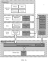
- FIG. 1b is a schematic diagram of modules of user equipment according to an implementation of this application.
- Example user equipment 1 includes, but is not limited to, a laptop device, a desktop computer, a handheld PC, a personal digital assistant, an embedded processor, a digital signal processor (digital signal processor, DSP for short), a graphics device, a video game device, a set-top box, a microcontroller, a cellular phone, a portable media player, a handheld device, a wearable device (for example, display glasses or goggles, a head-mounted display (head-mounted display, HMD for short), a watch, a head-mounted device, an armband or jewelry), virtual reality (virtual reality, VR for short) and/or augmented reality (augment reality, AR for short) devices, an Internet of Things (Internet of Things, IoT) device, a smart audio system, an in-vehicle infotainment device, a streaming media client device, an e-book reading device, a POS machine,
- the user equipment 1 may include one or more (only one is shown in the figure) processors 10, a sensor hub 12, and a Bluetooth communications module 14.
- the processor 10 may include, but is not limited to, a central processing unit (central processing unit, CPU), an application processor (application processor), a graphics processing unit (graphics processing unit, GPU), a digital signal processor (DSP), a micro-programmed control unit (micro-programmed control unit, MCU), an AI (artificial intelligence) processor or a field programmable gate array (field programmable gate array, FPGA), and other processing modules or processing circuits.
- the processor 10 may be configured to implement one or more of various embodiments described below.
- the processor 10 may run an operating system of the user equipment 1, such as Android, iOS, Windows OS, Linux, and Harmony operating system. In some other possible implementations, the processor 10 may run a specific application.
- the sensor hub 12 is mainly configured to connect various sensor devices and process data from the various sensor devices with low power consumption.
- the sensor hub 12 may include, but is not limited to, low-power processing modules or processing circuits such as a low-power application processor (application processor), a coprocessor (coprocessor), and a micro-programmed control unit (micro-programmed control unit).
- application processor application processor
- coprocessor coprocessor
- micro-programmed control unit micro-programmed control unit
- the sensor hub 12 can usually process, for example, data of sensors such as an accelerometer (accelerometer), a magnetometer (magnetometer), a gyroscope (gyroscope), an ambient light sensor (ambient light sensor), an optical proximity sensor (proximity), a barometer/pressure (barometer/pressure) and a humidometer (humidometer), and perform fusion processing on various sensor data.
- sensors such as an accelerometer (accelerometer), a magnetometer (magnetometer), a gyroscope (gyroscope), an ambient light sensor (ambient light sensor), an optical proximity sensor (proximity), a barometer/pressure (barometer/pressure) and a humidometer (humidometer), and perform fusion processing on various sensor data.
- sensors such as an accelerometer (accelerometer), a magnetometer (magnetometer), a gyroscope (gyroscope), an ambient light sensor (ambient light sensor), an optical proximity sensor (proximity), a barometer/pressure
- the sensor hub 12 may further process data related to Bluetooth communication, especially data related to BLE communication.
- the Bluetooth communications module 14 may be configured to communicate by using Bluetooth as well as Bluetooth low energy (BLE).
- Bluetooth has the full scope of its ordinary meaning, and includes at least any of various implementations of the existing Bluetooth standard, including Bluetooth low energy (BLE), and including future implementations of the Bluetooth standard, and the like.
- a Bluetooth connection includes a Bluetooth connection based on the Bluetooth protocol 4.x, such as 4.2, or includes a Bluetooth connection based on the Bluetooth protocol 5.x, such as 5.0.
- the Bluetooth connection may further include Bluetooth low energy (BLE). Compared with classic Bluetooth, the BLE aims to significantly reduce power consumption and cost while maintaining a communication range similar to that of the classic Bluetooth.
- the Bluetooth communications module 14 may be additionally combined with other communications modules, such as a module for Wi-Fi or WLAN (for example, 802.11) communication.
- a module for Wi-Fi or WLAN for example, 802.11
- the Bluetooth communications module 14 transmits data with the processor 10 by using a universal asynchronous receiver transmitter (universal asynchronous receiver transmitter, UART), and implements a Bluetooth function based on an instruction of the processor 10.
- UART universal asynchronous receiver transmitter
- a UART interface is a universal serial data bus for asynchronous communication, and the bus may be a bidirectional communication bus, which converts to-be-transmitted data between serial communication and parallel communication.
- the Bluetooth communications module 14 can further transmit data with the sensor hub 12 by using an inter integrated circuit (inter integrated circuit, I2C) or an improved inter integrated circuit (improved inter integrated circuit, I3C), and implement Bluetooth functions such as Bluetooth advertising (advertising, ADV), Bluetooth scanning (scanning), link establishment and data synchronization based on an instruction of the sensor hub 12.
- I2C interface is a bidirectional synchronous serial bus, and includes a serial data line (serial data line, SDA) and a serial clock line (serial clock line, SCL).
- I3C is an improvement to I2C, is compatible with the I2C protocol and combines the advantages of I2C (double-line, simple) and SPI (low power consumption, high speed).
- the processor 10 further shows a Bluetooth low energy (BLE) software architecture in an example Android system hierarchical architecture.
- BLE Bluetooth low energy
- a layered architecture divides the software into several layers, and each layer has a clear role and division of labor.
- the layers communicate with each other by using a software interface.
- the Android system is divided into four layers, which are respectively an application layer, an application framework layer, an HAL (hardware abstract layer, hardware abstract layer), and a kernel layer from top to bottom.
- the application layer may include a series of application packages. As shown in FIG. 1a and FIG. 1b , for Bluetooth/Bluetooth low energy communication, corresponding Bluetooth application packages may include applications such as settings, sharing, connection, and vicinity.
- the application framework layer provides an application programming interface (application programming interface, API) and a programming framework for applications at the application layer.
- the application framework layer includes some predefined functions.
- the application framework layer may include a Bluetooth architecture, a sensor architecture 101, and the like.
- the hardware abstract layer provides a unified access interface for different hardware devices.
- the HAL may include a Bluetooth protocol stack and a sensor HAL 102.
- the kernel layer is a layer between hardware and software.
- the kernel layer includes at least various drivers, such as a Bluetooth driver and a sensor driver 103 shown in FIG. 1b .
- the existing sensor hub does not have the ability to process Bluetooth communication data, cannot transmit data with the Bluetooth communications module.
- BLE needs to be used to query a list of nearby devices, and BLE scanning is initiated during the query, which leads to a poorer real-time performance of Bluetooth communication.
- key information interaction is first completed through BLE advertising, and then WLAN link establishment is initiated, which results in a slower link establishment speed.
- the device initiates data synchronization such as state synchronization through the BLE advertising, other devices are frequently awakened by the BLE advertising, causing a problem of higher power consumption.
- the sensor architecture 101, the sensor HAL 102 and the sensor driver 103 are modules added based on the existing Bluetooth communication software architecture of FIG. 1a , and form a new Bluetooth data transmission path, so that the processor 10 can obtain data related to Bluetooth communication from the sensor hub 12 and send data related to Bluetooth communication to the sensor hub 12.
- Bluetooth data from the sensor hub 12 can be uplinked sequentially by using the sensor driver 103, the sensor HAL 102, and the sensor architecture 101 to reach the Bluetooth application at the application layer.
- Bluetooth data from the Bluetooth application at the application layer can be downlinked to the sensor hub 12 by using the sensor architecture 101, the sensor HAL 102, and the sensor driver 103.
- the sensor hub 12 includes a Bluetooth application 121, a Bluetooth protocol stack 122, and a Bluetooth driver 123.
- the Bluetooth application 121, the Bluetooth protocol stack 122 and the Bluetooth driver 123 correspond to the Bluetooth architecture of the application framework layer, the Bluetooth protocol stack in the HAL and the Bluetooth driver in the kernel layer, respectively.
- the Bluetooth application 121 is implemented in the sensor hub 12 by transplanting at least some functions of the Bluetooth architecture of the application framework layer.
- the Bluetooth architecture of the application framework layer coded by JAVA is rewritten and transplanted to the sensor hub 12 by using C language to form the Bluetooth application 121.
- the Bluetooth protocol stack and the Bluetooth driver are transplanted from the processor end to the sensor hub 12 to form the Bluetooth protocol stack 122 and the Bluetooth driver 123.
- the Bluetooth protocol stack 122 may include corresponding Bluetooth protocols for advertising and scanning
- the Bluetooth driver 123 may include some or all drivers that drive the Bluetooth communications module 14.
- the Bluetooth protocol stack 122 has the same security protocol as the Bluetooth protocol stack of the processor 10, so that data security of the Bluetooth communication by using the sensor hub 12 can be protected by the Bluetooth security protocol.
- the Bluetooth communications module 14 may include a channel switching module 141, a controller 142, and a filter 143 stored (registered) in underlying internal logic.
- the filter 143 is configured to filter a result of the Bluetooth scanning such as BLE scanning. For example, when the processor 10 initiates the Bluetooth scanning, the filter 143 is generated based on a requirement of the Bluetooth scanning, and then transmitted from the processor 10 to the Bluetooth communications module 14 by using the UART, and stored in the underlying internal logic.
- the filter 143 can be generated in the Bluetooth application 121 of the sensor hub 12 based on the requirement of Bluetooth scanning, then transmitted from the sensor hub 12 to the Bluetooth communications module 14 by using the I2C/I3C, and stored in the underlying internal logic.
- the channel switching module 141 determines to send BLE data to at least one of the processor 10 and the sensor hub 12 based on an instruction of the controller 142.
- BLE communication-related applications such as advertising, scanning, and data synchronization by using the sensor hub 12
- downlinked BLE data of the processor 10 is sent to the sensor hub 12 sequentially by using the sensor architecture 101, the sensor HAL 102 and the sensor driver 103.
- the Bluetooth application 121 determines an application (service) to be executed, such as BLE advertising, BLE scanning and BLE state synchronization.
- An instruction to execute a corresponding service operation is transmitted to the Bluetooth protocol stack 122, and then the Bluetooth driver 123 is invoked to start the Bluetooth driver.
- the Bluetooth drive instruction is transmitted to the Bluetooth communications module 14 by using the I2C/I3C interface, and the Bluetooth communications module 14 starts BLE advertising and/or BLE scanning based on the Bluetooth drive instruction.
- the uplink transmission path of Bluetooth data obtained by the Bluetooth communications module 14 is implemented substantially by reverse transmission of the foregoing downlink transmission path, and the data transmission of Bluetooth communication is described in detail with reference to FIG. 2 to FIG. 4 .
- some functions for example, ADV/SCAN/BLE link establishment
- services of the Bluetooth protocol stack are set to the sensor hub 12, so that the user equipment according to the implementations of this application can perform BLE advertising and/or BLE scanning on the sensor hub 12 side when the processor 10 sleeps, to implement functions such as device discovery, obtaining of device link establishment information, device state synchronization for other user equipment, and power consumption of the device can be effectively reduced.
- the user equipment can increase speeds of device discovery, device link establishment and data synchronization.
- the increase in the speeds can be perceived, thereby optimizing user experience.
- Example communication processes in which the foregoing improved user equipment 1 implements Bluetooth advertising, Bluetooth scanning, Bluetooth link establishment and data synchronization are described separately below with reference to basic scenarios of Bluetooth communication.
- the detailed description of the communication processes and the comparison with the prior art further illustrate the significant technical effects achieved by the user equipment 1 of this application in Bluetooth communication.
- Bluetooth communication processes in some implementations are further described below with reference to FIG. 2 to FIG. 4 .
- these Bluetooth communication processes may be implemented on, for example, the user equipment 1 shown in FIG. 1b .
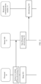
- FIG. 2 is a flowchart of Bluetooth advertising according to an implementation of this application.
- the processor 10 instructs to initiate offline advertising.
- the processor 10 may send an instruction for initiating offline Bluetooth advertising to the sensor hub 12.
- the instruction for offline Bluetooth advertising is used to instruct the processor 10 to go offline after the instruction is sent, to instruct the sensor hub 12 that the processor 10 is about to go offline, and to instruct the sensor hub 12 to start standard Bluetooth advertising or BLE advertising.
- the so-called "offline” means that the processor 10 goes to sleep after sending an instruction for offline Bluetooth advertising.
- the processor 10 in the sleep state does not process multiple applications such as the Bluetooth applications, thereby achieving the purpose of saving energy for the user equipment 1. That is, at block 202, the processor 10 sleeps and enters a sleep state.
- Bluetooth low energy advertising is used as an example for description below.
- the sensor hub 12 initiates Bluetooth advertising. Specifically, after receiving an instruction from the processor 10 for starting offline Bluetooth advertising such as BLE advertising, the sensor hub 12 starts the BLE advertising application in the Bluetooth application 121, and the Bluetooth protocol stack 122 sends an instruction to the Bluetooth driver 123 based on the Bluetooth advertising protocol.
- the Bluetooth driver 123 generates a Bluetooth advertising drive instruction, and sends the Bluetooth advertising drive instruction to the Bluetooth communications module 14 by using the I2C/I3C interface.
- the Bluetooth communications module 14 performs Bluetooth advertising (block 204). Therefore, during the process of performing, for example, BLE advertising, the processor 10 can remain in a sleep state, and data processing related to the advertising is performed in the sensor hub 12. Therefore, power consumption of the user equipment 1 is effectively reduced after the foregoing communication method is adopted.
- FIG. 2 The Bluetooth scanning process of the user equipment 1 is further described below.
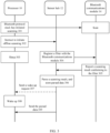
- FIG. 3 and FIG. 4 are flowcharts of possible Bluetooth scanning according to an implementation of this application.
- FIG. 3 shows a process in which the user equipment 1 performs Bluetooth scanning in a possible situation.
- the processor 10 instructs to initiate offline scanning.
- the processor 10 may send an instruction for initiating offline Bluetooth scanning to the sensor hub 12. Similar to the foregoing instruction for offline Bluetooth advertising, the instruction for offline Bluetooth scanning is used to instruct the processor 10 to go offline after the instruction is sent, to instruct the sensor hub 12 that the processor 10 is about to go offline, and to instruct the sensor hub 12 to start standard Bluetooth scanning or BLE scanning.
- the processor 10 sends the instruction for offline Bluetooth scanning, at block 303, the processor 10 enters a sleep state. Bluetooth low energy scanning is used as an example for description below.
- the Bluetooth protocol stack of the processor 10 has initiated scanning (block 301).
- the scanning may be Bluetooth scanning such as BLE scanning, that is, the Bluetooth communications module 14 may be performing or be about to perform Bluetooth scanning based on the instruction of the Bluetooth protocol stack of the processor 10.
- the sensor hub 12 does not need to instruct the Bluetooth communications module 14 again to initiate Bluetooth scanning.
- the content of block 301 may be used as a parameter in the instruction for offline Bluetooth scanning, or as a separate instruction sent to the sensor hub 12 along with the instruction for offline Bluetooth scanning, which is not limited herein in this application.
- a method in which the sensor hub 12 can learn whether the Bluetooth protocol stack of the processor 10 has initiated scanning is not limited in this application.
- the Bluetooth application 121 of the sensor hub 12 generates a filter 143 based on the instruction for offline Bluetooth scanning from the processor 10, and registers the filter 143 of the sensor hub 12 with the Bluetooth communications module 14 by using the Bluetooth protocol stack 122 and the Bluetooth driver 123 (block 304).
- the filter 143 can filter out data not needed by the sensor hub 12 from the Bluetooth advertising data scanned by the Bluetooth communications module 14.
- the Bluetooth communications module 14 reports a scanning result conforming to the filter, for example, reports the scanning result conforming to the filter to the sensor hub 12, or for example, sends the same to the Bluetooth application 121.
- the filter 143 filters the uplink data, and the filter 143 is configured with corresponding filtering parameters (rules) of the Bluetooth application.
- the rules may include judging whether the uplink data is broadcast data or scanned data of the sensor hub 12, judging whether the uplink data is broadcast data or scanned data of the processor 10, and judging whether the uplink data is one or more of other types of data of the processor 10. Uplink data that does not conform to the rules is directly discarded at an internal logic layer of the Bluetooth communications module 14. Uplink data conforming to the rules is transmitted to the channel switching module 141.
- the controller 142 controls the channel switching module 141 to send the filtered data to the sensor hub 12 and/or the processor 10 based on an instruction of the filter 143.
- the Bluetooth communications module 14 can implement UART and I2C/I3C concurrency. For example, data conforming to the filter of the sensor hub 12 is sent to the sensor hub 12 by using the I2C/I3C, data conforming to the filter of the processor 10 is sent to the processor 10 by using the UART, and data conforming to both filters will be sent to the processor 10 and the sensor hub 12 concurrently by using the UART and the I2C/I3C.
- the sensor hub 12 parses the reported scanning result and stores the parsed data. For example, if the scanning result is broadcast data, the Bluetooth application 121 parses data such as broadcast device address, broadcast access address and local name from the broadcast data. The parsed data may be stored in the sensor hub 12. It may be understood that the sensor hub 12 may include a volatile or non-volatile storage medium, such as a suitable dynamic random access memory (DRAM), a static random access memory (SRAM), or the like.
- DRAM dynamic random access memory
- SRAM static random access memory
- the sensor hub 12 can send a wake-up request to the processor 10 to wake up the processor 10 from the sleep state.
- the sensor hub 12 sends the parsed data, for example, the Bluetooth application 121 sends the parsed data to the processor 10.
- the processor 10 receives the parsed data by using the sensor driver 103, the data is uplinked and passes through the sensor HAL 102 and the sensor architecture 101 and reaches the application layer, and at the application layer, an application requesting for Bluetooth data may use the parsed data.
- the time for sending the wake-up request may be determined by the sensor hub 12 based on preset conditions.
- the sensor hub 12 may send a wake-up request after the capacity of the stored data reaches a predetermined size, such as 64 KB or 128 KB.
- the sensor hub 12 can extract one or more specific types of data from the parsed data, judge the extracted data based on preset conditions, and wake up the processor 10 based on a result of judgment.
- the selection of specific types of data and the determining of preset conditions may be set separately based on different usage scenarios of the user equipment 1, which will be described accordingly in the example usage scenarios of the user equipment 1 below.
- the sensor hub 12 may only store reported scanning results without further processing these scanning results.
- the sensor hub 12 may not need to wake up the processor 10, and the sensor hub 12 may send the stored data to the processor 10 when the processor 10 requests for the data.
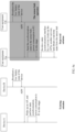
- FIG. 4 is a flowchart of another type of Bluetooth scanning according to an implementation of this application.
- the processor 10 instructs to initiate offline scanning.
- the processor 10 sends an instruction for starting offline Bluetooth scanning to the sensor hub 12.
- no Bluetooth scanning is performed based on the Bluetooth protocol stack of the processor 10. Therefore, at block 404, the sensor hub 12 needs to start, based on the instruction for initiating offline scanning from the processor 10, Bluetooth scanning and registers a filter with the Bluetooth communications module.
- the Bluetooth application 121 starts Bluetooth scanning and registers a filter for scanning with the Bluetooth communications module 14.
- the Bluetooth application 121 starts, based on the instruction of the processor 10, the BLE scanning application and generates a corresponding filter 143.
- the Bluetooth protocol stack 122 sends an instruction to the Bluetooth driver 123 based on the Bluetooth scanning protocol, and the Bluetooth driver 123 generates a Bluetooth scanning drive instruction, and sends the Bluetooth scanning drive instruction and the filter 143 to the Bluetooth communications module 14 by using the I2C interface to drive the Bluetooth communications module 14 to start Bluetooth scanning (block 405).
- a device A near the user equipment 1 sends a broadcast message M1 to the user equipment 1 for discovery by the user equipment 1.
- the broadcast message M1 of the device A may include a preamble, a message type and a current device ID.
- the preamble is used for filtering broadcast during BLE scanning, which improves the performance of broadcast processing, that is, the filter 143 filters out an unnecessary broadcast message based on the preamble of the broadcast message.
- the message type is used to distinguish between the types of different messages transmitted, and the current device ID is used to uniquely identify a sender's device.
- the user equipment 1 After initiating a scan, the user equipment 1 receives the broadcast message M1 from the device A. After passing through the filter 143, the broadcast message is sent to the Bluetooth application 121.
- the Bluetooth application 121 finds that the user equipment 1 does not cache link establishment information of the device A. Therefore, the user equipment 1 sends a message M2 to the device A, to indicate that user equipment 1 wants to obtain the link establishment information of the device A.
- the message M2 may include: a preamble, a message type, a current device ID, and a destination device ID.
- the destination device ID is used to identify a destination device to which the message is sent.
- a receiver device can use this destination device ID to match against its own device ID. If they are the same, it indicates that the receiver device can process the message.
- the device A replies to the user equipment 1 with its own link establishment information.
- the user equipment 1 receives link establishment information M3 sent by the device A.
- the message type, the current device ID and the destination device ID, M3 may further include: an SSID, a key and an MAC address of link establishment of the device A.
- the Bluetooth application 121 of the user equipment 1 parses the SSID, key and MAC address of link establishment from the link establishment information M3, and caches the same in the sensor hub 12.
- the processor 10 can obtain the parsed information from the Bluetooth application 121 of the sensor hub 12 by using the sensor driver 103, thereby quickly completing link establishment.
- the Bluetooth communication function that can only be implemented on the processor 10 side in the prior art can be additionally implemented in the sensor hub 12 in this application, for example, in the Bluetooth communication processes described in FIG. 2 to FIG. 4 .
- the user equipment 1 can perform BLE advertising and/or BLE scanning on the sensor hub 12 side when the processor 10 sleeps, to implement functions such as device discovery, subsequent obtaining of device link establishment information, device state synchronization for other user equipment, and therefore power consumption of the device can be effectively reduced.
- the sensor hub 12 because some functions of Bluetooth communication can be implemented in the sensor hub 12, it is possible for the sensor hub 12 to implement Bluetooth device discovery with low energy always enabled, and the sensor hub 12 can further store Bluetooth communication data parsed by the Bluetooth application 121. Therefore, the user equipment 1 can further increase the speeds of device discovery, device link establishment and data synchronization in the Bluetooth communication process. In addition, in one or more implementations, when the user uses the user equipment, the increase in the speeds can be perceived, thereby optimizing user experience. The following further refers to specific usage scenarios to describe the technical effects of increasing the Bluetooth communication speed.
- instructions sent by the processor 10 to the sensor hub 12 may be different in different application scenarios of this application.
- the processor 10 may send instructions for starting Bluetooth advertising and/or scanning instead of instructions for offline Bluetooth advertising and/or scanning.
- the following further describes the technical effects of this application with reference to various application scenarios of the implementations of this application.
- FIG. 5a to FIG. 5c show example usage scenarios of user equipment according to implementations of this application.
- At least one of user equipment 51a to 51d may be the user equipment 1 shown in FIG. 1 .
- a letter after the reference number such as "51a” indicates a reference to an element with the specific reference number.
- a reference number without a subsequent letter in the text, such as "51” indicates a general reference to the implementation of the element with the reference number.
- the user equipment 51a may be a Bluetooth speaker
- the user equipment 51b may be a notebook computer
- the user equipment 51c may be a smart TV
- the user equipment 51d may be a smart phone.
- FIG. 5a shows an example scenario in which the user equipment is networked through WLAN multi-hop (multi-hop).
- each piece of user equipment 51 uses a wireless MESH technology for networking.
- FIG. 5b shows an example scenario in which the user equipment 51 is networked by using the same wireless AP (access point).
- FIG. 5c shows an example scenario in which the user equipment 51 is networked through Bluetooth low energy (BLE/BTLE) advertising.
- BLE/BTLE Bluetooth low energy
- the user equipment 51a and 51b are within the wireless communication range, which will not be described subsequently.
- the networking process of the user equipment 51a and 51b is described with reference to FIG. 6 .
- networking processes of the prior art and this application are compared in FIG. 6 .
- the networking process in the prior art is only used as an example of a usual networking process, and is used only as a reference example for describing the technical solution of this application, will not be described in detail, and will be mentioned only when necessary.
- the user equipment 51a and 51b are used as a master device and the user equipment 51b is used as a slave device.
- This limitation is only for convenience of description and understanding of the implementation, and is not a specific limitation on this application.
- FIG. 6a shows a process of quick discovery of a plurality of pieces of user equipment in the foregoing scenario.
- the time required for the device A and a device B to discover each other is T1+T2+T3.
- the application layer of the processor of the device A initiates a device discovery request
- the Bluetooth communications module initiates BLE scanning.
- the time required from the service side of the device A initiating the request to the Bluetooth communications module initiating the scanning is T1.
- the Bluetooth communications module of the device A receives the BLE advertising sent by the device B, and the time required for receiving the advertising is T2.
- the Bluetooth communications module of the device A reports the advertising packet to the application layer of the processor by using the Bluetooth protocol stack, and the time required for reporting the advertising packet is T3.
- the user equipment 51b when the user equipment 51a and the user equipment 51b are within the discoverable range, the user equipment 51b periodically initiates BLE advertising in the background, and the sensor hub of the user equipment 51a and/or the sensor hub of the user equipment 51b are/is processing Bluetooth communication.
- the application layer of the processor of the user equipment 51a initiates the device discovery request, for example, when the user equipment 51a is sleeping, the user equipment 51a keeps BLE scanning always enabled with a lower duty cycle in the background by using the sensor hub, and starts BLE advertising.
- the Bluetooth communications module of the user equipment 51a receives the BLE advertising sent by the user equipment 51b.
- the Bluetooth communications module of the user equipment 51a reports the adverting packet to the sensor hub, which does not affect the dormancy of the processor of the user equipment 51a.
- the processor can read the previously obtained BLE advertising of the user equipment 51b from the sensor hub, and the time required to obtain the advertising packet is T4. In this implementation of this application, it can be determined that the time for device discovery is T4, and T4 is less than T3 and much less than T1+T2+T3.
- the sensor architecture 101, the sensor HAL 102, and the sensor driver 103 and other modules are used to directly obtain the device list cached in the sensor hub, thereby implementing quick discovery between devices. This greatly increases the response speed of presenting the device list on the user equipment for the user.
- the WLAN link establishment process involves the synchronization of key information.
- the time required for the device A and the device B to complete WLAN link establishment is T1+T2.
- the device A and the device B exchange link establishment key information through BLE advertising.
- the time required to exchange keys through BLE advertising is T1.
- the device A and device B initiate WLAN link establishment, and the time required for WLAN link establishment is T2.
- the user equipment 51a and the user equipment 51b after the user equipment 51a and the user equipment 51b discover each other, the user equipment 51a and/or the user equipment 51b exchange key information for link establishment by using the sensor hubs in the background.
- the application layer of the processor of the user equipment 51a initiates a link establishment request, the processor can read the previously cached key information from the sensor hub.
- the user equipment 51a obtains the key information
- the user equipment 51a and the user equipment 51b initiate WLAN link establishment, and the time required for WLAN link establishment is T2.
- it can be determined that the time for WLAN link establishment between devices is T2, and T2 is less than T1+T2.
- link establishment information interaction with low energy always enabled is implemented by using the sensor hub, and WLAN link establishment information is cached to the sensor hub.
- the sensor architecture 101, the sensor HAL 102, and the sensor driver 103 and other modules are used to directly obtain the WLAN link establishment information at the sensor hub, thereby implementing quick device link establishment.
- the technical solution of this application enables the user to initiate data transmission after he/she selects the destination device to which data is transmitted, thereby effectively improving user experience.
- the device B and the user equipment 51b are low battery devices.
- the device A sleeps, and the device B has a low battery.
- the device B broadcasts the low battery state of the device through BLE, and the Bluetooth communications module of the device A receives the low battery state broadcast by the device B and wakes up the processor of the device A to update the device state. It is assumed that power consumption of processor wake-up and state synchronization is P1.
- the Bluetooth communications module of the user equipment 51a after receiving the low battery state of the user equipment 51b, the Bluetooth communications module of the user equipment 51a sends the state to the sensor hub.
- the sensor hub can synchronize the device state. It is assumed that the power consumption for the sensor hub to synchronize the device state is P2.
- the device state may be saved in the sensor hub.
- the processor of the user equipment 51a when the processor of the user equipment 51a is woken up by other applications, the processor may obtain the saved low battery state of the user equipment 51b from the sensor hub. Therefore, in this example, the power consumption for state synchronization is only P2. Under the same actual test conditions, the power consumption increment value corresponding to P1 is about 8.28 mA, and the power consumption increment value of the sensor hub corresponding to P2 is about 0.001 mA.
- the sensor hub is used to achieve state synchronization with low energy always enabled, which can significantly reduce the power consumption of the user equipment.
- the sensor hub of the user equipment 51a may determine based on the low battery state of the user equipment 51b whether to actively wake up the processor of the user equipment 51a. As an example, when the low battery state indicates that the remaining power (for example, the remaining power is 15%) is lower than a preset threshold (for example, the preset threshold is 20%), the sensor hub actively wakes up the processor and reports the low battery state.
- the preset threshold can be configured by the sensor hub, or configured by the processor and then sent to the sensor hub for storage. The sensor hub can determine whether specific data reaches the preset threshold when parsing data reported by other devices, such as low battery state data.
- data synchronization is not limited to the foregoing low battery state synchronization.
- the user equipment in the foregoing implementations may further synchronize other state data for different applications.
- the user equipment in the foregoing implementations may need to synchronize data such as the load state of the processor, the device battery state, and running applications of the devices.
- the user equipment when the user equipment needs distributed computing resources, before the user equipment distributes computing tasks to other devices in the network, the user equipment may need to judge based on the synchronization states of other devices whether other devices can perform computing tasks.
- the user equipment may exclude devices with low battery and/or devices running specific applications, and the specific applications may include, for example, call applications and high-load applications such as game applications.
- the devices run these applications, if computing tasks are distributed to the devices, the running applications may be obviously adversely affected.
- the foregoing various state data can be synchronized in the sensor hub of the user equipment, and the processor of the user equipment can obtain synchronization data of other devices from the sensor hub before distributing computing tasks.
- the sensor hub may further determine whether to wake up the processor and report the state data. For example, in distributed computing, if the processor load of other devices changes greatly, for example, changes from the low load to the high load in a short time, or vice versa, against the jump of the state data, the sensor hub can directly wake up the dormant processor and report the state information.
- the user equipment 51a may further perform quick state synchronization by using the sensor hub.
- the user equipment 51a cannot scan the BLE advertising sent by the user equipment 51b, a timeout mechanism is triggered after a period of time, and the sensor hub of the user equipment 51a deletes the user equipment 51b from the device list and caches the device list.
- the processor of the user equipment 51a can directly obtain the real-time scan list from the sensor hub.
- the user equipment needs to rescan the device before synchronizing the device list, and then update the device list.
- BLE links may be used between user equipment to transmit synchronization data.
- a transmission method of data synchronization is not limited.
- the user basically does not need to wait when starting a wireless connection.
- the user dictates an instruction "I want to watch the movie Transformers 4" to the user equipment 51a (smart speaker). Because the user equipment 51a has completed quick discovery, quick networking and low energy quick state synchronization between devices, the user equipment 51a directly reads properties and states corresponding to the devices in the whole network from the sensor hub, and finds that the user equipment 51c (smart TV) is suitable for playing movies, then the user equipment 51a sends an instruction for playing Transformers 4 to the user equipment 51c, and the user equipment 51c starts playing the movie. Therefore, in this scenario, within a short time after the user gives the instruction, the target device can respond to the user's instruction to perform the corresponding task.
- the target device can respond to the user's instruction to perform the corresponding task.
- scanning and synchronization of device properties and state are usually initiated only when a service comes.
- the user needs to wait for a certain period of time before obtaining a response from the device, which cannot meet the user's requirements for the device.
- the power consumption of the processor in processing Bluetooth communication is 8.28 mA
- the power consumption of the processor in processing the Bluetooth communication is 14.47 mA
- the power consumption of the processor in processing the Bluetooth communication is 24.35 mA.
- the operating voltage of the sensor hub is 0.75 V, and the operating current is: 11 mA.
- the sensor hub processes broadcast data once for about 2 ms, and processes broadcasts for 100 times in 10 minutes.
- the total power consumption of the sensor hub and DDR storage accounts for only one-eight thousandths of the processor's power consumption of 8.28 mA on average. Therefore, it may be understood that the user equipment according to the technical solution of this application can significantly reduce power consumption in Bluetooth communication.
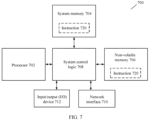
- FIG. 7 is a block diagram of a communications device 700 according to an embodiment of this application.
- the device 700 may include one or more processors 702, system control logic 708 connected to at least one of the processors 702, a system memory 704 connected to the system control logic 708, a non-volatile memory (NVM) 706 connected to the system control logic 708, and a network interface 710 connected to the system control logic 708.
- processors 702 system control logic 708 connected to at least one of the processors 702, a system memory 704 connected to the system control logic 708, a non-volatile memory (NVM) 706 connected to the system control logic 708, and a network interface 710 connected to the system control logic 708.
- NVM non-volatile memory
- the processor 702 may include one or more single-core or multi-core processors.
- the processor 702 may include any combination of a general-purpose processor and a specific processor (for example, a graphics processor, an application processor or a baseband processor).
- the processor 702 may be configured to implement one or more of various embodiments shown in FIG. 2 to FIG. 4 .
- system control logic 708 may include any suitable interface controller to provide any suitable interface to at least one of the processors 702 and/or any suitable device or component in communication with the system control logic 708.
- system control logic 708 may include one or more memory controllers to provide an interface connected to the system memory 704.
- the system memory 704 may be configured to load and store data and/or instructions.
- the memory 704 of the device 700 may include any suitable volatile memory, such as a suitable dynamic random access memory (DRAM).
- DRAM dynamic random access memory
- the NVM/memory 706 may include one or more tangible and non-transitory computer readable media for storing data and/or instructions.
- the NVM/memory 706 may include any suitable non-volatile memory such as a flash memory and/or any suitable non-volatile storage device, for example, at least one of an HDD (hard disk drive, hard disk drive), a CD (compact disc, optical disc) drive, a DVD (digital versatile disc, digital versatile disc) drive.
- HDD hard disk drive, hard disk drive
- CD compact disc, optical disc
- DVD digital versatile disc, digital versatile disc
- the NVM/ memory 706 may include some storage resources installed on an apparatus of the device 700, or may be accessed by the device, but is not necessarily a part of the device. For example, the NVM/ memory 706 may be accessed over a network by using the network interface 710.
- the system memory 704 and the NVM/memory 706 may include a temporary copy and a permanent copy of an instruction 720, respectively.
- the instruction 720 may include an instruction that, when executed by at least one of the processors 702, enables the device 700 to implement the methods shown in FIG. 2 to FIG. 5 .
- the instruction 720, hardware, firmware and/or software components thereof may additionally/alternatively be placed in the system control logic 708, the network interface 710 and/or the processor 702.
- the network interface 710 may include a transceiver configured to provide a radio interface to the device 700 to communicate with any other suitable device (such as a front-end module or an antenna) by using one or more networks.
- the network interface 710 may be integrated on another component of the device 700.
- the network interface 710 may be integrated on at least one of the processor 702, the system memory 704, the NVM/memory 706, and a firmware device (not shown) with instructions.
- the device 700 implements one or more of the various embodiments shown in FIG. 2 to FIG. 4 .
- the network interface 710 may further include any suitable hardware and/or firmware to provide a multi-input multi-output radio interface.
- the network interface 710 may be a network adapter, a wireless network adapter, a telephone modem, and/or a wireless modem.
- At least one of the processors 702 may be packaged with logic of one or more controllers for the system control logic 708 to form a system in a package (SiP). In an embodiment, at least one of the processors 702 may be integrated on the same die with the logic of one or more controllers for the system control logic 708 to form a system on chip (SoC).
- SiP system in a package
- SoC system on chip
- the device 700 may further include: an input/output (I/O) device 712.
- the I/O device 712 may include a user interface to enable the user to interact with the device 700; and the design of a peripheral component interface enables a peripheral component to also interact with the device 700.
- the device 700 further includes a sensor, configured to determine at least one of an environmental condition and location information related to the device 700.
- the user interface may include, but is not limited to, a display (for example, a liquid crystal display or a touch screen display), a speaker, a microphone, one or more cameras (for example, a still-picture camera and/or a video camera), a flashlight (for example, a light-emitting diode flash) and a keyboard.
- a display for example, a liquid crystal display or a touch screen display
- a speaker for example, a speaker, a microphone
- one or more cameras for example, a still-picture camera and/or a video camera
- a flashlight for example, a light-emitting diode flash
- the peripheral component interface may include, but is not limited to, a non-volatile memory port, an audio jack, and a power interface.
- the senor may include, but is not limited to, a gyro sensor, an accelerometer, a proximity sensor, an ambient light sensor and a positioning unit.
- the positioning unit may alternatively be a part of the network interface 710 or interact with the network interface 710 to communicate with components (for example, global positioning system (GPS) satellites) of a positioning network.
- GPS global positioning system
- Implementations of the method of this application may be implemented by using software, magnetic components, firmware, or the like.
- Program code may be applied to input instructions to perform the functions described herein and generate output information.
- the output information may be applied to one or more output devices in a known manner.
- a processing system includes any system having a processor such as a digital signal processor (DSP), a microcontroller, an application-specific integrated circuit (ASIC), or a microprocessor.
- DSP digital signal processor
- ASIC application-specific integrated circuit
- the program code may be implemented in a high-level programming language or an object-oriented programming language to communicate with the processing system.
- an assembly language or machine language may also be used to implement the program code.
- the mechanism described herein is not limited to the scope of any particular programming language. In any case, the language may be a compiled language or an interpreted language.
- IP cores may be stored on a tangible computer readable storage medium and provided to a plurality of customers or production facilities to be loaded into a manufacturing machine that actually manufactures the logic or the processor.
- an instruction converter may be used to convert instructions from a source instruction set to a target instruction set.
- the instruction converter can transform (for example, by using static binary conversion, or dynamic binary conversion including dynamic compilation), deform, simulate or convert in other manners the instructions into one or more other instructions to be processed by a core.
- the instruction converter may be implemented by software, hardware, firmware, or a combination thereof.
- the instruction converter may be on the processor, outside the processor, or partly on the processor and partly outside the processor.
Landscapes
- Engineering & Computer Science (AREA)
- Computer Networks & Wireless Communication (AREA)
- Signal Processing (AREA)
- Computer Security & Cryptography (AREA)
- Databases & Information Systems (AREA)
- Multimedia (AREA)
- Mobile Radio Communication Systems (AREA)
- Telephone Function (AREA)
- Transceivers (AREA)
Claims (9)
- Ein drahtloses Kommunikationsverfahren, angewendet auf einen Coprozessor eines Geräts, wobei der Coprozessor einen Sensor-Hub (12) umfasst, der zumindest teilweise zur Verarbeitung von Sensordaten von einem oder mehreren Sensoren des Geräts konfiguriert ist, und das Verfahren umfasst:Empfangen einer Anweisung von einem Prozessor (10) des Geräts zum Starten von Offline-Bluetooth-Werbung, wobei die Anweisung für Offline-Bluetooth-Werbung verwendet wird, um den Prozessor (10) anzuweisen, offline zu gehen, nachdem die Anweisung gesendet wurde, um den Sensor-Hub (12) anzuweisen, dass der Prozessor (10) offline gehen wird, und um den Sensor-Hub (12) anzuweisen, Standard-Bluetooth-Werbung oder Bluetooth-Low-Energy-Werbung zu starten;als Reaktion auf die Anweisung des Prozessors (10) Starten der Bluetooth-Werbung und Generieren einer Antriebsanweisung zum Ansteuern eines drahtlosen Kommunikationsmoduls (14) des Geräts zur Durchführung von drahtlosen Übertragungen, wobei die drahtlosen Übertragungen Bluetooth-Werbung oder Bluetooth-Low-Energy-Werbung umfassen; undSenden der Antriebsanweisung an das drahtlose Kommunikationsmodul (14).
- Das Verfahren nach Anspruch 1, wobei das Verfahren ferner umfasst:
Empfangen von Daten des drahtlosen Kommunikationsdienstes, die während der drahtlosen Kommunikation vom drahtlosen Kommunikationsmodul (14) erhalten wurden. - Das Verfahren nach Anspruch 2, wobei das Verfahren ferner umfasst:Speichern der Daten im Coprozessor; oderAnalysieren der Daten basierend auf dem drahtlosen Kommunikationsdienst und Speichern der analysierten Daten im Coprozessor.
- Das Verfahren nach Anspruch 3, wobei das Verfahren ferner umfasst:
Lesen und Senden der im Coprozessor gespeicherten Daten an den Prozessor (10) als Antwort auf eine Anforderung des Prozessors (10). - Ein drahtloses Kommunikationsgerät, wobei das Gerät umfasst:einen Prozessor (10);einen Coprozessor, der einen Sensor-Hub (12) umfasst, der zumindest teilweise zur Verarbeitung von Sensordaten von einem oder mehreren Sensoren des Geräts konfiguriert ist; undein drahtloses Kommunikationsmodul (14), wobei das drahtlose Kommunikationsmodul (14) in einer kommunizierenden Weise mit dem Prozessor (10) und dem Coprozessor gekoppelt ist;Der Prozessor (10) ist konfiguriert, eine Anweisung zum Starten von Offline-Bluetooth-Werbung an den Coprozessor zu senden, wobei die Anweisung für Offline-Bluetooth-Werbung verwendet wird, um den Prozessor (10) anzuweisen, nach dem Senden der Anweisung offline zu gehen, den Sensor-Hub (12) darüber zu informieren, dass der Prozessor (10) offline gehen wird, und den Sensor-Hub (12) anzuweisen, standardmäßige Bluetooth-Werbung oder Bluetooth-Low-Energy-Werbung zu starten;Der Coprozessor ist konfiguriert, basierend auf der Anweisung des Prozessors (10) Bluetooth-Werbung zu initiieren und eine Antriebsanweisung zu generieren, um das drahtlose Kommunikationsmodul (14) zur Durchführung von drahtlosen Übertragungen anzutreiben, wobei die drahtlosen Übertragungen Bluetooth-Werbung oder Bluetooth-Low-Energy-Werbung umfassen; undDas drahtlose Kommunikationsmodul (14) ist konfiguriert, die Antriebsanweisung vom Coprozessor zu empfangen und die drahtlosen Übertragungen basierend auf der Antriebsanweisung durchzuführen.
- Die Vorrichtung nach Anspruch 5, wobei der Prozessor (10) weiterhin konfiguriert ist, eine Vielzahl von Datenverbindungen zu umfassen, und eine der Datenverbindungen ist konfiguriert, die Anweisung an den Coprozessor zu senden und Daten des drahtlosen Kommunikationsdienstes des Coprozessors zu empfangen.
- Die Vorrichtung nach einem der Ansprüche 5 bis 6, wobei der Coprozessor weiterhin konfiguriert ist, von dem drahtlosen Kommunikationsmodul (14) eine Broadcast-Nachricht von mindestens einem zweiten Gerät, das nicht die Vorrichtung ist, zu empfangen.
- Die Vorrichtung nach Anspruch 7, wobei der Coprozessor weiterhin konfiguriert ist:Die Broadcast-Nachricht im Coprozessor zu speichern; undDie gespeicherte Broadcast-Nachricht auf Anfrage des Prozessors (10) an den Prozessor (10) zu senden.
- Ein computerlesbares Speichermedium, wobei Anweisungen auf dem computerlesbaren Speichermedium gespeichert sind und wenn die Anweisungen von einem Computer ausgeführt werden, der Computer in die Lage versetzt wird, das drahtlose Kommunikationsverfahren nach einem der Ansprüche 1 bis 4 auszuführen.
Priority Applications (1)
| Application Number | Priority Date | Filing Date | Title |
|---|---|---|---|
| EP25161228.9A EP4607978A3 (de) | 2020-01-14 | 2020-12-31 | Drahtloskommunikationsverfahren und -vorrichtung mit drahtloskommunikationsfunktion |
Applications Claiming Priority (2)
| Application Number | Priority Date | Filing Date | Title |
|---|---|---|---|
| CN202010036703.5A CN111263339B (zh) | 2020-01-14 | 2020-01-14 | 无线通信方法和具有无线通信功能的设备 |
| PCT/CN2020/142195 WO2021143541A1 (zh) | 2020-01-14 | 2020-12-31 | 无线通信方法和具有无线通信功能的设备 |
Related Child Applications (1)
| Application Number | Title | Priority Date | Filing Date |
|---|---|---|---|
| EP25161228.9A Division EP4607978A3 (de) | 2020-01-14 | 2020-12-31 | Drahtloskommunikationsverfahren und -vorrichtung mit drahtloskommunikationsfunktion |
Publications (3)
| Publication Number | Publication Date |
|---|---|
| EP4080920A1 EP4080920A1 (de) | 2022-10-26 |
| EP4080920A4 EP4080920A4 (de) | 2023-06-14 |
| EP4080920B1 true EP4080920B1 (de) | 2025-04-02 |
Family
ID=70948816
Family Applications (2)
| Application Number | Title | Priority Date | Filing Date |
|---|---|---|---|
| EP25161228.9A Pending EP4607978A3 (de) | 2020-01-14 | 2020-12-31 | Drahtloskommunikationsverfahren und -vorrichtung mit drahtloskommunikationsfunktion |
| EP20914087.0A Active EP4080920B1 (de) | 2020-01-14 | 2020-12-31 | Drahtloses kommunikationsverfahren und vorrichtung, die eine drahtlose kommunikationsfunktion aufweist |
Family Applications Before (1)
| Application Number | Title | Priority Date | Filing Date |
|---|---|---|---|
| EP25161228.9A Pending EP4607978A3 (de) | 2020-01-14 | 2020-12-31 | Drahtloskommunikationsverfahren und -vorrichtung mit drahtloskommunikationsfunktion |
Country Status (5)
| Country | Link |
|---|---|
| US (1) | US12262308B2 (de) |
| EP (2) | EP4607978A3 (de) |
| JP (1) | JP7389264B2 (de) |
| CN (2) | CN111263339B (de) |
| WO (1) | WO2021143541A1 (de) |
Families Citing this family (19)
| Publication number | Priority date | Publication date | Assignee | Title |
|---|---|---|---|---|
| CN111263339B (zh) * | 2020-01-14 | 2021-06-04 | 荣耀终端有限公司 | 无线通信方法和具有无线通信功能的设备 |
| CN114257996B (zh) * | 2020-09-21 | 2025-09-02 | 华为技术有限公司 | 一种设备的发现方法和装置 |
| CN114531449A (zh) * | 2020-10-31 | 2022-05-24 | 华为终端有限公司 | 数据同步方法及装置 |
| CN114554463B (zh) * | 2020-11-24 | 2026-01-23 | 华为终端有限公司 | 蓝牙通信方法、蓝牙广播方法、蓝牙设备以及存储介质 |
| CN118467044A (zh) * | 2020-12-18 | 2024-08-09 | Oppo广东移动通信有限公司 | 系统切换方法、装置、设备及存储介质 |
| CN113438633B (zh) * | 2021-06-18 | 2023-03-31 | 深圳松诺技术有限公司 | 通信数据处理方法、终端和计算机可读存储介质 |
| CN113438628B (zh) * | 2021-06-23 | 2022-07-05 | 京东科技控股股份有限公司 | 用于数据交互的方法和装置 |
| CN113641413B (zh) * | 2021-08-25 | 2024-05-07 | Oppo广东移动通信有限公司 | 目标模型加载更新方法及装置、可读介质和电子设备 |
| CN114995591B (zh) * | 2021-10-30 | 2023-01-20 | 荣耀终端有限公司 | 传感器注册方法、控制系统及相关设备 |
| CN114356804B (zh) * | 2021-12-28 | 2024-05-31 | 北京奕斯伟计算技术股份有限公司 | 通信方法、装置、设备、计算机可读存储介质及程序产品 |
| CN116419424A (zh) * | 2021-12-31 | 2023-07-11 | Oppo广东移动通信有限公司 | 设备连接方法、装置、设备、存储介质及程序产品 |
| CN114979974B (zh) * | 2022-04-13 | 2024-07-26 | 深圳市智岩科技有限公司 | 无线控制方法、装置及设备 |
| CN114827922A (zh) * | 2022-05-13 | 2022-07-29 | 山东亚微软件股份有限公司 | 一种电子桌牌控制方法、装置和介质 |
| CN117528477A (zh) * | 2022-07-27 | 2024-02-06 | 华为技术有限公司 | 一种设备间连接的管理方法、设备及系统 |
| CN115407864A (zh) * | 2022-09-30 | 2022-11-29 | 维沃移动通信有限公司 | 数据处理方法、数据处理装置、电子设备和可读存储介质 |
| CN115696527B (zh) * | 2022-10-25 | 2026-03-17 | 网易有道(杭州)智能科技有限公司 | 一种调节电子设备功耗的方法和系统 |
| CN118540684A (zh) * | 2023-02-10 | 2024-08-23 | 荣耀终端有限公司 | 一种蓝牙广播请求的处理方法及设备 |
| KR20250133777A (ko) * | 2023-02-12 | 2025-09-08 | 애플 인크. | 연속적인 디바이스 상호작용 발견 |
| CN116546600B (zh) * | 2023-05-11 | 2026-02-24 | 广州芯之联科技有限公司 | 一种蓝牙数据包的过滤方法、系统、装置及存储介质 |
Citations (1)
| Publication number | Priority date | Publication date | Assignee | Title |
|---|---|---|---|---|
| EP2713662A2 (de) * | 2012-09-28 | 2014-04-02 | Samsung Electronics Co., Ltd | Betriebsverfahren für energiearme Kurzstreckenkommunikationsfunktion und Vorrichtung eines mobilen Endgeräts |
Family Cites Families (46)
| Publication number | Priority date | Publication date | Assignee | Title |
|---|---|---|---|---|
| US7898994B2 (en) * | 2002-02-25 | 2011-03-01 | Hewlett-Packard Development Company, L.P. | Power saving in multi-processor device |
| US7266389B2 (en) * | 2002-08-12 | 2007-09-04 | Broadcom Corporation | Device for selective power management for a hand held host |
| US7814304B2 (en) | 2007-03-14 | 2010-10-12 | Apple Inc. | Switching drivers between processors |
| CN101355786A (zh) * | 2007-07-23 | 2009-01-28 | 中国移动通信集团公司 | 通信业务的触发方法、系统以及触发设备 |
| US20090259865A1 (en) | 2008-04-11 | 2009-10-15 | Qualcomm Incorporated | Power Management Using At Least One Of A Special Purpose Processor And Motion Sensing |
| US20100141400A1 (en) * | 2008-11-19 | 2010-06-10 | Qualcomm Incorporated | Lower power discovery and wake up using service set identifier probabilistic scanning synchronization verification and optional sensor |
| US9749176B2 (en) | 2010-06-29 | 2017-08-29 | Nokia Technologies Oy | Systems, methods, and apparatuses for providing adaptive user notifications |
| CN102684720B (zh) | 2011-03-09 | 2016-09-14 | 费希尔控制国际公司 | 用于在过程控制或监测环境中进行无线通信的方法和装置 |
| US9497563B2 (en) | 2011-09-23 | 2016-11-15 | Google Inc. | Mobile device activation |
| CN102594636A (zh) * | 2012-02-21 | 2012-07-18 | 无锡聚联智能电子科技有限公司 | 一种基于多种无线协议的家庭智能网关系统和控制方法 |
| US9152211B2 (en) * | 2012-10-30 | 2015-10-06 | Google Technology Holdings LLC | Electronic device with enhanced notifications |
| KR102069863B1 (ko) * | 2012-11-12 | 2020-01-23 | 삼성전자주식회사 | 입력 수단의 결제 기능을 제어하는 전자 장치 및 방법 |
| US10912131B2 (en) * | 2012-12-03 | 2021-02-02 | Samsung Electronics Co., Ltd. | Method and mobile terminal for controlling bluetooth low energy device |
| WO2014119894A1 (en) * | 2013-01-29 | 2014-08-07 | Samsung Electronics Co., Ltd. | Method of performing function of device and device for performing the method |
| KR102060661B1 (ko) * | 2013-07-19 | 2020-02-11 | 삼성전자주식회사 | 통신 방법 및 이를 위한 디바이스 |
| JP6338344B2 (ja) | 2013-10-04 | 2018-06-06 | キヤノン株式会社 | 通信装置、通信装置の制御方法およびプログラム |
| CN103619056B (zh) | 2013-12-02 | 2018-01-12 | 华为终端(东莞)有限公司 | 一种上报传感器数据的方法和终端 |
| KR102016644B1 (ko) | 2014-02-23 | 2019-08-30 | 삼성전자주식회사 | 전자 장치의 기능 및 리소스 운용 방법 |
| CN103942176B (zh) * | 2014-04-29 | 2016-09-07 | 活点信息技术有限公司 | 一种传感器hub |
| US10209062B1 (en) * | 2014-08-01 | 2019-02-19 | Google Llc | Use of offline algorithm to determine location from previous sensor data when location is requested |
| US20160095060A1 (en) * | 2014-09-26 | 2016-03-31 | Intel Corporation | METHOD AND APPARATUS FOR POWER OPTIMIZED IoT COMMUNICATION |
| US9357342B2 (en) * | 2014-10-07 | 2016-05-31 | Google Inc. | Short-range wireless controller filtering and reporting |
| KR102349713B1 (ko) * | 2014-10-20 | 2022-01-12 | 삼성전자주식회사 | 장치 검색 방법 및 이를 지원하는 전자 장치 |
| KR20160054850A (ko) * | 2014-11-07 | 2016-05-17 | 삼성전자주식회사 | 다수의 프로세서들을 운용하는 장치 및 방법 |
| KR102274730B1 (ko) * | 2014-11-26 | 2021-07-08 | 삼성전자주식회사 | 전자 장치 및 전자 장치에서의 정보 전송 방법 |
| US20180329713A1 (en) * | 2014-12-10 | 2018-11-15 | Intel Corporation | Fitness sensor with low power attributes in sensor hub |
| US10206170B2 (en) * | 2015-02-05 | 2019-02-12 | Apple Inc. | Dynamic connection path detection and selection for wireless controllers and accessories |
| US9626227B2 (en) * | 2015-03-27 | 2017-04-18 | Intel Corporation | Technologies for offloading and on-loading data for processor/coprocessor arrangements |
| US9706493B2 (en) | 2015-06-26 | 2017-07-11 | Intel IP Corporation | Bluetooth low energy devices, systems, and associated methods |
| DE112016005840B4 (de) | 2016-01-21 | 2021-06-17 | Mitsubishi Electric Corporation | Drahtloses kommunikationsgerät, drahtloses kommunikationsverfahren und programm für drahtlose kommunikation |
| KR102498362B1 (ko) * | 2016-05-03 | 2023-02-10 | 삼성전자주식회사 | 위치 정보 계산 방법 및 그 전자 장치 |
| CN107451090B (zh) * | 2016-06-01 | 2020-09-11 | 华为技术有限公司 | 数据处理系统和数据处理方法 |
| CN106197468B (zh) * | 2016-06-24 | 2018-02-02 | 广东欧珀移动通信有限公司 | 计步器步数更新的方法及系统 |
| CN106535313A (zh) * | 2016-12-22 | 2017-03-22 | 宇龙计算机通信科技(深圳)有限公司 | 一种移动终端通信方法及通信系统 |
| CN108668239B (zh) * | 2017-03-28 | 2021-08-24 | 无锡壹人一灯科技发展有限公司 | 低功耗并支持一对多交互的无线通信系统及其通信方法 |
| CN107918596B (zh) * | 2017-11-14 | 2023-09-05 | 上海坤锐电子科技有限公司 | 一种soc芯片及射频信号处理方法 |
| KR102480875B1 (ko) | 2017-12-04 | 2022-12-26 | 삼성전자주식회사 | 블루투스 통신을 재연결하는 방법 및 장치 |
| CN108111975A (zh) * | 2017-12-27 | 2018-06-01 | 天津恒达文博科技股份有限公司 | 基于wifi及多传感器技术的多方式、多平台互动笔式终端 |
| WO2019192030A1 (zh) * | 2018-04-04 | 2019-10-10 | 华为技术有限公司 | 一种蓝牙播放方法及电子设备 |
| CN108924805B (zh) * | 2018-07-13 | 2021-05-14 | 杭州网易云音乐科技有限公司 | 蓝牙连接方法、介质和第一、第二电子设备以及计算设备 |
| CN111209904A (zh) * | 2018-11-21 | 2020-05-29 | 华为技术有限公司 | 一种业务处理的方法以及相关装置 |
| US11153721B2 (en) * | 2018-12-27 | 2021-10-19 | Intel Corporation | Sensor network enhancement mechanisms |
| CN109951893A (zh) * | 2019-03-21 | 2019-06-28 | 青岛海信电器股份有限公司 | 一种终端设备唤醒方法及装置 |
| CN110401939B (zh) * | 2019-09-04 | 2023-03-24 | 大唐半导体科技有限公司 | 一种低功耗蓝牙控制器链路层装置 |
| KR102749983B1 (ko) * | 2019-10-28 | 2025-01-03 | 삼성전자주식회사 | 외부 전자 장치와 주변 장치를 공유하는 전자 장치 및 그 방법 |
| CN111263339B (zh) * | 2020-01-14 | 2021-06-04 | 荣耀终端有限公司 | 无线通信方法和具有无线通信功能的设备 |
-
2020
- 2020-01-14 CN CN202010036703.5A patent/CN111263339B/zh active Active
- 2020-01-14 CN CN202110712778.5A patent/CN113490191B/zh active Active
- 2020-12-31 JP JP2022543022A patent/JP7389264B2/ja active Active
- 2020-12-31 EP EP25161228.9A patent/EP4607978A3/de active Pending
- 2020-12-31 EP EP20914087.0A patent/EP4080920B1/de active Active
- 2020-12-31 WO PCT/CN2020/142195 patent/WO2021143541A1/zh not_active Ceased
- 2020-12-31 US US17/792,648 patent/US12262308B2/en active Active
Patent Citations (1)
| Publication number | Priority date | Publication date | Assignee | Title |
|---|---|---|---|---|
| EP2713662A2 (de) * | 2012-09-28 | 2014-04-02 | Samsung Electronics Co., Ltd | Betriebsverfahren für energiearme Kurzstreckenkommunikationsfunktion und Vorrichtung eines mobilen Endgeräts |
Also Published As
| Publication number | Publication date |
|---|---|
| EP4607978A2 (de) | 2025-08-27 |
| JP7389264B2 (ja) | 2023-11-29 |
| EP4080920A1 (de) | 2022-10-26 |
| CN113490191B (zh) | 2024-05-31 |
| CN111263339A (zh) | 2020-06-09 |
| EP4080920A4 (de) | 2023-06-14 |
| CN111263339B (zh) | 2021-06-04 |
| US20230047724A1 (en) | 2023-02-16 |
| WO2021143541A1 (zh) | 2021-07-22 |
| JP2023510368A (ja) | 2023-03-13 |
| CN113490191A (zh) | 2021-10-08 |
| US12262308B2 (en) | 2025-03-25 |
| EP4607978A3 (de) | 2025-10-22 |
Similar Documents
| Publication | Publication Date | Title |
|---|---|---|
| EP4080920B1 (de) | Drahtloses kommunikationsverfahren und vorrichtung, die eine drahtlose kommunikationsfunktion aufweist | |
| US12581411B2 (en) | Sleep scheduling method and device | |
| US10004095B2 (en) | Method and apparatus for communicating using multiple frequency bands | |
| US20220264462A1 (en) | Wake-up signal configuration method, wake-up signal processing method, and related device | |
| KR102804216B1 (ko) | 전자 장치 및 이의 통신 데이터 링크를 스케쥴링하는 방법 | |
| CN114554463B (zh) | 蓝牙通信方法、蓝牙广播方法、蓝牙设备以及存储介质 | |
| US12484097B2 (en) | Method for monitoring link and terminal device | |
| CN113645608A (zh) | 数据传输方法和数据传输装置 | |
| CN113597002B (zh) | 下行接收触发方法、终端和网络侧设备 | |
| US20210127431A1 (en) | Electronic device for transmitting data to external electronic device not connected thereto, and operation method of electronic device | |
| WO2023142993A1 (zh) | 一种探测方法、相关电子设备及系统 | |
| WO2023083068A1 (zh) | 唤醒对齐方法、系统及相关装置 | |
| CN117528477A (zh) | 一种设备间连接的管理方法、设备及系统 | |
| CN120151957A (zh) | 连接管理方法、电子设备及系统 | |
| RU2803186C1 (ru) | Способ беспроводной связи и устройство, имеющее функцию беспроводной связи | |
| CN114698069B (zh) | 通信方法和设备 | |
| EP4633113A1 (de) | Datensynchronisationsverfahren, elektronische vorrichtung und system | |
| CN120091393B (zh) | 控制方法及相关装置 | |
| CN118139214B (zh) | 一种用于设备的连接方法 | |
| CN119011601B (zh) | 数据同步方法、电子设备及系统 | |
| CN118843180A (zh) | 数据状态同步方法及电子设备 | |
| CN119997043A (zh) | 建立蓝牙连接的方法及电子设备 | |
| CN118057898A (zh) | 电子设备间的通信方法、通信系统、电子设备和存储介质 | |
| CN121711663A (zh) | 近距离无线通信的广播方法及相关装置 | |
| CN121728438A (zh) | 一种蓝牙通信方法及电子设备 |
Legal Events
| Date | Code | Title | Description |
|---|---|---|---|
| STAA | Information on the status of an ep patent application or granted ep patent |
Free format text: STATUS: THE INTERNATIONAL PUBLICATION HAS BEEN MADE |
|
| PUAI | Public reference made under article 153(3) epc to a published international application that has entered the european phase |
Free format text: ORIGINAL CODE: 0009012 |
|
| STAA | Information on the status of an ep patent application or granted ep patent |
Free format text: STATUS: REQUEST FOR EXAMINATION WAS MADE |
|
| 17P | Request for examination filed |
Effective date: 20220720 |
|
| AK | Designated contracting states |
Kind code of ref document: A1 Designated state(s): AL AT BE BG CH CY CZ DE DK EE ES FI FR GB GR HR HU IE IS IT LI LT LU LV MC MK MT NL NO PL PT RO RS SE SI SK SM TR |
|
| DAV | Request for validation of the european patent (deleted) | ||
| DAX | Request for extension of the european patent (deleted) | ||
| A4 | Supplementary search report drawn up and despatched |
Effective date: 20230512 |
|
| RIC1 | Information provided on ipc code assigned before grant |
Ipc: H04W 8/00 20090101ALI20230508BHEP Ipc: H04W 4/06 20090101ALI20230508BHEP Ipc: H04W 52/02 20090101ALI20230508BHEP Ipc: G06F 15/163 20060101ALI20230508BHEP Ipc: H04W 4/80 20180101AFI20230508BHEP |
|
| STAA | Information on the status of an ep patent application or granted ep patent |
Free format text: STATUS: EXAMINATION IS IN PROGRESS |
|
| 17Q | First examination report despatched |
Effective date: 20231017 |
|
| GRAP | Despatch of communication of intention to grant a patent |
Free format text: ORIGINAL CODE: EPIDOSNIGR1 |
|
| STAA | Information on the status of an ep patent application or granted ep patent |
Free format text: STATUS: GRANT OF PATENT IS INTENDED |
|
| INTG | Intention to grant announced |
Effective date: 20241025 |
|
| GRAS | Grant fee paid |
Free format text: ORIGINAL CODE: EPIDOSNIGR3 |
|
| GRAA | (expected) grant |
Free format text: ORIGINAL CODE: 0009210 |
|
| STAA | Information on the status of an ep patent application or granted ep patent |
Free format text: STATUS: THE PATENT HAS BEEN GRANTED |
|
| AK | Designated contracting states |
Kind code of ref document: B1 Designated state(s): AL AT BE BG CH CY CZ DE DK EE ES FI FR GB GR HR HU IE IS IT LI LT LU LV MC MK MT NL NO PL PT RO RS SE SI SK SM TR |
|
| REG | Reference to a national code |
Ref country code: GB Ref legal event code: FG4D |
|
| REG | Reference to a national code |
Ref country code: CH Ref legal event code: EP |
|
| REG | Reference to a national code |
Ref country code: DE Ref legal event code: R096 Ref document number: 602020048928 Country of ref document: DE |
|
| REG | Reference to a national code |
Ref country code: IE Ref legal event code: FG4D |
|
| REG | Reference to a national code |
Ref country code: NL Ref legal event code: FP |
|
| REG | Reference to a national code |
Ref country code: AT Ref legal event code: MK05 Ref document number: 1782484 Country of ref document: AT Kind code of ref document: T Effective date: 20250402 |
|
| PG25 | Lapsed in a contracting state [announced via postgrant information from national office to epo] |
Ref country code: PT Free format text: LAPSE BECAUSE OF FAILURE TO SUBMIT A TRANSLATION OF THE DESCRIPTION OR TO PAY THE FEE WITHIN THE PRESCRIBED TIME-LIMIT Effective date: 20250804 Ref country code: ES Free format text: LAPSE BECAUSE OF FAILURE TO SUBMIT A TRANSLATION OF THE DESCRIPTION OR TO PAY THE FEE WITHIN THE PRESCRIBED TIME-LIMIT Effective date: 20250402 Ref country code: FI Free format text: LAPSE BECAUSE OF FAILURE TO SUBMIT A TRANSLATION OF THE DESCRIPTION OR TO PAY THE FEE WITHIN THE PRESCRIBED TIME-LIMIT Effective date: 20250402 |
|
| REG | Reference to a national code |
Ref country code: LT Ref legal event code: MG9D |
|
| PG25 | Lapsed in a contracting state [announced via postgrant information from national office to epo] |
Ref country code: NO Free format text: LAPSE BECAUSE OF FAILURE TO SUBMIT A TRANSLATION OF THE DESCRIPTION OR TO PAY THE FEE WITHIN THE PRESCRIBED TIME-LIMIT Effective date: 20250702 Ref country code: GR Free format text: LAPSE BECAUSE OF FAILURE TO SUBMIT A TRANSLATION OF THE DESCRIPTION OR TO PAY THE FEE WITHIN THE PRESCRIBED TIME-LIMIT Effective date: 20250703 |
|
| PG25 | Lapsed in a contracting state [announced via postgrant information from national office to epo] |
Ref country code: PL Free format text: LAPSE BECAUSE OF FAILURE TO SUBMIT A TRANSLATION OF THE DESCRIPTION OR TO PAY THE FEE WITHIN THE PRESCRIBED TIME-LIMIT Effective date: 20250402 |
|
| PG25 | Lapsed in a contracting state [announced via postgrant information from national office to epo] |
Ref country code: BG Free format text: LAPSE BECAUSE OF FAILURE TO SUBMIT A TRANSLATION OF THE DESCRIPTION OR TO PAY THE FEE WITHIN THE PRESCRIBED TIME-LIMIT Effective date: 20250402 |
|
| PG25 | Lapsed in a contracting state [announced via postgrant information from national office to epo] |
Ref country code: HR Free format text: LAPSE BECAUSE OF FAILURE TO SUBMIT A TRANSLATION OF THE DESCRIPTION OR TO PAY THE FEE WITHIN THE PRESCRIBED TIME-LIMIT Effective date: 20250402 |
|
| PG25 | Lapsed in a contracting state [announced via postgrant information from national office to epo] |
Ref country code: AT Free format text: LAPSE BECAUSE OF FAILURE TO SUBMIT A TRANSLATION OF THE DESCRIPTION OR TO PAY THE FEE WITHIN THE PRESCRIBED TIME-LIMIT Effective date: 20250402 |
|
| PG25 | Lapsed in a contracting state [announced via postgrant information from national office to epo] |
Ref country code: RS Free format text: LAPSE BECAUSE OF FAILURE TO SUBMIT A TRANSLATION OF THE DESCRIPTION OR TO PAY THE FEE WITHIN THE PRESCRIBED TIME-LIMIT Effective date: 20250702 |
|
| PG25 | Lapsed in a contracting state [announced via postgrant information from national office to epo] |
Ref country code: IS Free format text: LAPSE BECAUSE OF FAILURE TO SUBMIT A TRANSLATION OF THE DESCRIPTION OR TO PAY THE FEE WITHIN THE PRESCRIBED TIME-LIMIT Effective date: 20250802 |
|
| PG25 | Lapsed in a contracting state [announced via postgrant information from national office to epo] |
Ref country code: LV Free format text: LAPSE BECAUSE OF FAILURE TO SUBMIT A TRANSLATION OF THE DESCRIPTION OR TO PAY THE FEE WITHIN THE PRESCRIBED TIME-LIMIT Effective date: 20250402 |
|
| PGFP | Annual fee paid to national office [announced via postgrant information from national office to epo] |
Ref country code: NL Payment date: 20251112 Year of fee payment: 6 |
|
| REG | Reference to a national code |
Ref country code: DE Ref legal event code: R097 Ref document number: 602020048928 Country of ref document: DE |
|
| PGFP | Annual fee paid to national office [announced via postgrant information from national office to epo] |
Ref country code: DE Payment date: 20251104 Year of fee payment: 6 |
|
| PGFP | Annual fee paid to national office [announced via postgrant information from national office to epo] |
Ref country code: GB Payment date: 20251114 Year of fee payment: 6 |
|
| PG25 | Lapsed in a contracting state [announced via postgrant information from national office to epo] |
Ref country code: DK Free format text: LAPSE BECAUSE OF FAILURE TO SUBMIT A TRANSLATION OF THE DESCRIPTION OR TO PAY THE FEE WITHIN THE PRESCRIBED TIME-LIMIT Effective date: 20250402 Ref country code: SM Free format text: LAPSE BECAUSE OF FAILURE TO SUBMIT A TRANSLATION OF THE DESCRIPTION OR TO PAY THE FEE WITHIN THE PRESCRIBED TIME-LIMIT Effective date: 20250402 |
|
| PG25 | Lapsed in a contracting state [announced via postgrant information from national office to epo] |
Ref country code: CZ Free format text: LAPSE BECAUSE OF FAILURE TO SUBMIT A TRANSLATION OF THE DESCRIPTION OR TO PAY THE FEE WITHIN THE PRESCRIBED TIME-LIMIT Effective date: 20250402 |
|
| PG25 | Lapsed in a contracting state [announced via postgrant information from national office to epo] |
Ref country code: EE Free format text: LAPSE BECAUSE OF FAILURE TO SUBMIT A TRANSLATION OF THE DESCRIPTION OR TO PAY THE FEE WITHIN THE PRESCRIBED TIME-LIMIT Effective date: 20250402 |
|
| PG25 | Lapsed in a contracting state [announced via postgrant information from national office to epo] |
Ref country code: SK Free format text: LAPSE BECAUSE OF FAILURE TO SUBMIT A TRANSLATION OF THE DESCRIPTION OR TO PAY THE FEE WITHIN THE PRESCRIBED TIME-LIMIT Effective date: 20250402 |
|
| PG25 | Lapsed in a contracting state [announced via postgrant information from national office to epo] |
Ref country code: IT Free format text: LAPSE BECAUSE OF FAILURE TO SUBMIT A TRANSLATION OF THE DESCRIPTION OR TO PAY THE FEE WITHIN THE PRESCRIBED TIME-LIMIT Effective date: 20250402 |
|
| PLBE | No opposition filed within time limit |
Free format text: ORIGINAL CODE: 0009261 |
|
| STAA | Information on the status of an ep patent application or granted ep patent |
Free format text: STATUS: NO OPPOSITION FILED WITHIN TIME LIMIT |
|
| PG25 | Lapsed in a contracting state [announced via postgrant information from national office to epo] |
Ref country code: RO Free format text: LAPSE BECAUSE OF FAILURE TO SUBMIT A TRANSLATION OF THE DESCRIPTION OR TO PAY THE FEE WITHIN THE PRESCRIBED TIME-LIMIT Effective date: 20250402 |
|
| REG | Reference to a national code |
Ref country code: CH Ref legal event code: L10 Free format text: ST27 STATUS EVENT CODE: U-0-0-L10-L00 (AS PROVIDED BY THE NATIONAL OFFICE) Effective date: 20260211 |
|
| 26N | No opposition filed |
Effective date: 20260105 |