EP4080941A1 - Verfahren zum führen einer intelligenten vorrichtung zu einem zugangsnetz, und medium, steuerendgerät und system - Google Patents
Verfahren zum führen einer intelligenten vorrichtung zu einem zugangsnetz, und medium, steuerendgerät und system Download PDFInfo
- Publication number
- EP4080941A1 EP4080941A1 EP21744738.2A EP21744738A EP4080941A1 EP 4080941 A1 EP4080941 A1 EP 4080941A1 EP 21744738 A EP21744738 A EP 21744738A EP 4080941 A1 EP4080941 A1 EP 4080941A1
- Authority
- EP
- European Patent Office
- Prior art keywords
- smart device
- control terminal
- network configuration
- management application
- smart
- Prior art date
- Legal status (The legal status is an assumption and is not a legal conclusion. Google has not performed a legal analysis and makes no representation as to the accuracy of the status listed.)
- Granted
Links
Images


Classifications
-
- H—ELECTRICITY
- H04—ELECTRIC COMMUNICATION TECHNIQUE
- H04W—WIRELESS COMMUNICATION NETWORKS
- H04W76/00—Connection management
- H04W76/10—Connection setup
-
- H—ELECTRICITY
- H04—ELECTRIC COMMUNICATION TECHNIQUE
- H04W—WIRELESS COMMUNICATION NETWORKS
- H04W48/00—Access restriction; Network selection; Access point selection
- H04W48/18—Selecting a network or a communication service
-
- H—ELECTRICITY
- H04—ELECTRIC COMMUNICATION TECHNIQUE
- H04M—TELEPHONIC COMMUNICATION
- H04M1/00—Substation equipment, e.g. for use by subscribers
- H04M1/72—Mobile telephones; Cordless telephones, i.e. devices for establishing wireless links to base stations without route selection
- H04M1/724—User interfaces specially adapted for cordless or mobile telephones
- H04M1/72403—User interfaces specially adapted for cordless or mobile telephones with means for local support of applications that increase the functionality
- H04M1/72406—User interfaces specially adapted for cordless or mobile telephones with means for local support of applications that increase the functionality by software upgrading or downloading
-
- H—ELECTRICITY
- H04—ELECTRIC COMMUNICATION TECHNIQUE
- H04L—TRANSMISSION OF DIGITAL INFORMATION, e.g. TELEGRAPHIC COMMUNICATION
- H04L12/00—Data switching networks
- H04L12/28—Data switching networks characterised by path configuration, e.g. LAN [Local Area Networks] or WAN [Wide Area Networks]
- H04L12/2803—Home automation networks
- H04L12/2807—Exchanging configuration information on appliance services in a home automation network
- H04L12/2809—Exchanging configuration information on appliance services in a home automation network indicating that an appliance service is present in a home automation network
-
- H—ELECTRICITY
- H04—ELECTRIC COMMUNICATION TECHNIQUE
- H04L—TRANSMISSION OF DIGITAL INFORMATION, e.g. TELEGRAPHIC COMMUNICATION
- H04L12/00—Data switching networks
- H04L12/28—Data switching networks characterised by path configuration, e.g. LAN [Local Area Networks] or WAN [Wide Area Networks]
- H04L12/2803—Home automation networks
- H04L12/2823—Reporting information sensed by appliance or service execution status of appliance services in a home automation network
- H04L12/2825—Reporting to a device located outside the home and the home network
-
- H—ELECTRICITY
- H04—ELECTRIC COMMUNICATION TECHNIQUE
- H04L—TRANSMISSION OF DIGITAL INFORMATION, e.g. TELEGRAPHIC COMMUNICATION
- H04L12/00—Data switching networks
- H04L12/28—Data switching networks characterised by path configuration, e.g. LAN [Local Area Networks] or WAN [Wide Area Networks]
- H04L12/2803—Home automation networks
- H04L12/283—Processing of data at an internetworking point of a home automation network
- H04L12/2834—Switching of information between an external network and a home network
-
- H—ELECTRICITY
- H04—ELECTRIC COMMUNICATION TECHNIQUE
- H04M—TELEPHONIC COMMUNICATION
- H04M1/00—Substation equipment, e.g. for use by subscribers
- H04M1/72—Mobile telephones; Cordless telephones, i.e. devices for establishing wireless links to base stations without route selection
- H04M1/724—User interfaces specially adapted for cordless or mobile telephones
- H04M1/72403—User interfaces specially adapted for cordless or mobile telephones with means for local support of applications that increase the functionality
-
- H—ELECTRICITY
- H04—ELECTRIC COMMUNICATION TECHNIQUE
- H04W—WIRELESS COMMUNICATION NETWORKS
- H04W48/00—Access restriction; Network selection; Access point selection
- H04W48/16—Discovering, processing access restriction or access information
-
- H—ELECTRICITY
- H04—ELECTRIC COMMUNICATION TECHNIQUE
- H04W—WIRELESS COMMUNICATION NETWORKS
- H04W84/00—Network topologies
- H04W84/02—Hierarchically pre-organised networks, e.g. paging networks, cellular networks, WLAN [Wireless Local Area Network] or WLL [Wireless Local Loop]
- H04W84/10—Small scale networks; Flat hierarchical networks
- H04W84/12—WLAN [Wireless Local Area Networks]
-
- H—ELECTRICITY
- H04—ELECTRIC COMMUNICATION TECHNIQUE
- H04W—WIRELESS COMMUNICATION NETWORKS
- H04W48/00—Access restriction; Network selection; Access point selection
- H04W48/08—Access restriction or access information delivery, e.g. discovery data delivery
- H04W48/10—Access restriction or access information delivery, e.g. discovery data delivery using broadcasted information
Definitions
- This application relates to a method for guiding a smart device to connect to a network, a medium, a control terminal, and a system.
- a user After purchasing a smart device (for example, a power strip, an air purifier, or a desk lamp), a user usually needs to first connect the smart device to a wireless communications network, for example, a Wi-Fi network, before using the smart device for the first time.
- a wireless communications network for example, a Wi-Fi network
- the user When connecting the smart device to a network, the user usually needs to first install, on a control terminal such as a mobile phone, a device management application (application, APP) of a manufacturer, and then connect the smart device to the network on the device management APP of the manufacturer according to guidance (this process is briefly referred to as "network configuration" in this application).
- the user may have smart devices from different manufacturers. Devices from different manufacturers usually require different device management APPs to support network configuration. Therefore, the user needs to download APPs of different manufacturers and complete network configuration on each of the APPs of different manufacturers.
- An objective of this application is to provide a solution for guiding network configuration of a device, to simplify a network configuration operation of a smart device.
- a first aspect of this application provides a method for guiding a smart device to connect to a wireless network.
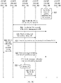
- the method may include: a smart device sends a device ID and a cloud service address that are of the smart device to a control terminal; the control terminal receives the device ID and the cloud service address that are sent by the smart device, and sends, based on the device ID, a network configuration information obtaining request to a cloud server corresponding to the cloud service address, where the information obtaining request is used to obtain network configuration information required by the smart device to access a wireless network; the cloud server sends the network configuration information to the control terminal in response to the received network configuration information obtaining request sent by the control terminal; the control terminal receives the network configuration information, and determines a management application of the smart device based on the network configuration information; and the control terminal sends the network configuration information to the management application, where the network configuration information can be used by the management application to guide the smart device to connect to a wireless network.
- the device management APP corresponding to the smart device is automatically determined through interaction between the control terminal, the smart device, and the cloud server of the smart device, and a user does not need to actively search for or download the device management APP of the smart device, thereby simplifying a network configuration operation of the smart device.
- the control terminal in the foregoing method may communicate with the smart device by using a Wi-Fi protocol.
- the control terminal may be used as an access point, and the smart device may be used as a station to connect to Wi-Fi created by the control terminal. That is, before the smart device sends a device ID and a cloud service address that are of the smart device to a control terminal, the foregoing method may further include: the control terminal sends a first Wi-Fi broadcast signal; and that the smart device sends a device ID and a cloud service address that are of the smart device may specifically include: the smart device sends a first probe request signal based on the received first Wi-Fi broadcast signal, where the first probe request signal includes the device ID and the cloud service address.
- control terminal and the smart device in the foregoing method may still communicate with each other by using a Wi-Fi protocol.
- the smart device may be used as an access point, and the control terminal is used as a station to connect to Wi-Fi created by the smart device.
- the method may further include: the smart device sends a second Wi-Fi broadcast signal; and the control terminal sends a second probe request signal to the smart device based on the received second Wi-Fi broadcast signal; and that the smart device sends a device ID and a cloud service address that are of the smart device may include: the smart device sends a second probe response signal based on the received second probe request signal, where the second probe response signal includes the device ID and the cloud service address.
- the method may further include: the control terminal downloads the determined management application of the smart device from the cloud server, and installs the management application.
- the method may further include: the control terminal determines that the management application of the smart device is installed on the control terminal, and guides a user to open the management application.
- control terminal interacts with the intelligent device to automatically determine the device management APP corresponding to the smart device, and guides the user to download and install or directly open the device management APP corresponding to the smart device, thereby simplifying an operation of connecting to a wireless network by the smart device.
- a second aspect of this application provides another method for guiding a smart device to connect to a wireless network.
- the method may be performed by a control terminal, and includes: the control terminal receives a device ID and a cloud service address that are of a smart device and that are sent by the smart device; the control terminal obtains, based on the device ID and from a cloud server corresponding to the cloud service address, network configuration information required by the smart device to connect to a wireless network, and determines a management application of the smart device; and the control terminal sends the network configuration information to the management application, where the network configuration information can be used by the management application to guide the smart device to connect to the wireless network.
- control terminal obtains the information sent by the smart device to automatically determine the device management APP corresponding to the smart device, and a user does not need to actively search for or download the device management APP of the smart device, thereby simplifying a network configuration operation of the smart device.
- the method may further include: the control terminal downloads the determined management application of the smart device from the cloud server corresponding to the cloud service address, and installs the management application.
- the control terminal automatically downloads the device management APP based on the device ID and the cloud service address. A user does not need to manually search for and download the device management APP, thereby simplifying a network configuration operation.
- the method may further include: the control terminal determines that the determined management application of the smart device is installed on the control terminal; and the control terminal guides a user to open the management application.
- the control terminal directly prompts the user and opens the device management APP, thereby simplifying a network configuration operation.
- the method may further include: the control terminal obtains network information of a wireless network that is selected by a user and to which the smart device is to connect; and the control terminal verifies an identity of the user, and when the verification succeeds, the control terminal sends the network information of the wireless network to the management application, where the network information can be used by the management application to connect the smart device to the wireless network selected by the user.
- the control terminal in the foregoing method may communicate with the smart device by using a Wi-Fi protocol.
- the control terminal may be used as an access point, and the smart device is used as a station to connect to Wi-Fi created by the control terminal. That is, before the control terminal receives a device ID and a cloud service address that are of a smart device and that are sent by the smart device, the method may further include: the control terminal sends a first Wi-Fi broadcast signal; and that the control terminal receives a device ID and a cloud service address that are of a smart device and that are sent by the smart device may include: the control terminal receives a first probe request signal from the smart device, where the first probe request signal includes the device ID and the cloud service address, and the first probe request signal is sent by the smart device based on the received first Wi-Fi broadcast signal sent by the control terminal.
- the Wi-Fi broadcast signal includes information indicating that connection of the smart device to a wireless network is supported. Therefore, it is convenient for the smart device to determine and connect to a Wi-Fi network. For example, when receiving a plurality of Wi-Fi broadcast signals, the smart device may preferentially connect to a Wi-Fi network that carries information indicating that connection of the smart device to the wireless network is supported.
- the method may further include: the control terminal receives from the management application, a message indicating that the smart device connects to the wireless network; and the control terminal displays information indicating that network configuration of the smart device succeeds, and disables the Wi-Fi broadcast.
- control terminal and the smart device in the foregoing method may communicate with each other may communicate with each other by using a Wi-Fi protocol.
- the smart device may be used as an access point, and the control terminal is used as a station to connect to Wi-Fi created by the smart device.
- the method may further include: the control terminal receives a second Wi-Fi broadcast signal sent by the smart device; and the control terminal sends a second probe request signal to the smart device; and that the control terminal receives a device ID and a cloud service address that are of a smart device and that are sent by the smart device includes: the control terminal receives a second probe response signal from the smart device, where the second probe response signal includes the device ID and the cloud service address, and the second probe response signal is sent by the smart device based on the received second probe request signal.
- the method may further include: the control terminal downloads the determined management application of the smart device from the cloud server corresponding to the cloud service address, and establishes a Wi-Fi connection to the smart device after the management application is downloaded.
- An occasion at which the control terminal establishes the Wi-Fi connection to the smart device is set to a time period after the device management APP is downloaded, but not a time period before the management APP is downloaded, so that frequent network switching of the control terminal can be avoided.
- an occasion at which the control terminal establishes the Wi-Fi connection to the smart device may alternatively be set to a time period before the management APP is downloaded.
- the control terminal disconnects from the Wi-Fi created by the smart device, and re-connects to the Wi-Fi created by the smart device after the downloading is completed.
- the method may further include: the control terminal receives from the management application, a message indicating that the smart device connects to the wireless network; and the control terminal displays information indicating that network configuration of the smart device succeeds, and disconnects the Wi-Fi connection to the smart device.
- the control terminal may automatically determine the device management APP corresponding to the smart device, and guide the user to download and install or directly open the device management APP corresponding to the smart device, thereby simplifying an operation of connecting to a wireless network by the smart device.
- the network configuration operation of the smart device is performed by using the device management APP, because the control terminal has established a communication connection to the smart device, in a network configuration process, a password of a wireless network to which the smart device is to connect does not need to be broadcast, so that security of the network configuration process can be improved.
- the method includes: the control terminal displays a user interface, where the user interface includes a first mode and a second mode; and the control terminal determines that the first mode is selected.
- the method includes: the control terminal displays a user interface, where the user interface includes a first mode and a second mode; and the control terminal determines that the second mode is selected.
- the user can perform a network configuration operation by entering the interface provided in this embodiment of this application, and does not need to separately search for, download, and perform an operation on different management applications for different smart devices.
- the user interface further includes at least some of the network configuration information of the smart device and corresponding information that is related to the management application, and an interaction option used to guide a user to download or open the management application.
- the user can conveniently view and manage a smart device that waits for network configuration and a smart device on which network configuration has been performed.
- a third aspect of this application provides still another method for guiding a smart device to connect to a wireless network.
- the method may include: a control terminal receives a first device ID and a first cloud service address that are of a first smart device and that are sent by the first smart device; the control terminal obtains, from a cloud server corresponding to the first cloud service address and based on the first device ID, first network configuration information required by the first smart device to connect to a wireless network, and determines a first management application of the first smart device; and the control terminal sends the first network configuration information to the first management application, where the first network configuration information can be used by the first management application to guide the first smart device to connect to a wireless network; and the control terminal receives a second device ID and a second cloud service address that are of a second smart device and that are sent by the second smart device; the control terminal obtains, from a cloud server corresponding to the second cloud service address and based on the second device ID, second network configuration information required by the second smart device to connect to a wireless network
- a fourth aspect of this application provides a machine readable medium.
- the machine readable medium can store instructions. When the instructions are run by a machine, the machine can perform the method provided in any one of the second aspect, the third aspect, the implementations of the second aspect, or the implementations of the third aspect.
- a fifth aspect of this application provides a control terminal, including a memory and a processor, where the memory stores instructions, and the processor is configured to read and execute the instructions in the memory, so that the control terminal performs the method provided in any one of the second aspect, the third aspect, the implementations of the second aspect, or the implementations of the third aspect.
- a sixth aspect of this application provides a system.
- the system may include the control terminal and the smart device provided in any one of the fifth aspect or the implementations of the fifth aspect.
- a seventh aspect of this application provides an apparatus.
- the apparatus has a function of implementing the method provided in any one of the second aspect, the third aspect, the implementations of the second aspect, or the implementations of the third aspect.
- the function may be implemented by hardware, or may be implemented by hardware executing corresponding software.
- the hardware or software includes one or more modules corresponding to the foregoing function.
- An eighth aspect of this application provides a computer program product.
- the computer program product includes program code, and when the computer program product is executed by a controller, the controller performs the method provided in any one of the second aspect, the third aspect, the implementations of the second aspect, or the implementations of the third aspect.
- the computer program product may be a software installation package.
- the computer program product may be downloaded to the controller, and the computer program product may be run on the controller.
- the control terminal can interact with the smart device to automatically determine the device management APP corresponding to the smart device, and guide the user to download and install or directly open the device management APP corresponding to the smart device, thereby simplifying a network configuration operation of the smart device.
- the network configuration operation of the smart device is performed by using the device management APP, because the control terminal has established a communication connection to the smart device, in a network configuration process, a password of a wireless network to which the smart device is to connect does not need to be broadcast, so that security of the network configuration process can be improved.
- Illustrative embodiments of this application include but are not limited to a method for guiding a device to connect to a network, a medium, a control terminal, and a system.
- a smart device for example, a power strip, an air purifier, or a desk lamp
- a user After purchasing a smart device (for example, a power strip, an air purifier, or a desk lamp), a user usually needs to connect the smart device to a network to facilitate control by the user.
- a process of guiding a smart device to connect to a network may be briefly referred to as "network configuration".
- a smart device may include various devices that can interact with a cloud or another device through a network.
- FIG. 1 shows an example of a scenario of network configuration of a device according to some embodiments of this application.
- a reference numeral followed by a letter, such as "300a” represents a reference to an element having that specified reference numeral
- a reference numeral without being followed by a letter, such as "300” represents a general reference to an implementation of an element having that reference numeral.
- the smart device 300 As shown in FIG. 1 , after a smart device 300 such as a smart air purifier 300a, a smart desk lamp 300b, and a smart power strip 300c is purchased, the smart device 300 usually needs to be connected to a network before being used. If the smart device 300 needs to be connected to a network, for example, home Wi-Fi provided by a wireless access point 400 such as a router shown in FIG. 1 , a user usually needs to perform corresponding configuration by using a control terminal 100 such as a mobile phone. For example, the user may download, from a cloud server 200 of the device by using the mobile phone, a device management application (application, App) corresponding to the smart device 300, and perform a corresponding operation on the device management APP to complete network configuration of the device 300.
- a device management application application, App
- the smart device 300 is in an access point (access point, AP) mode, and creates a Wi-Fi hotspot.
- a user establishes a communication connection to the Wi-Fi hotspot of the device by using a device management APP on the mobile phone, and then sends, to the smart device, a name and a password that are of the home Wi-Fi provided by the wireless access point 400.
- the smart device 300 connects to the home Wi-Fi based on the obtained name and password of the home Wi-Fi.
- the smart device is used as an AP, and the mobile phone is used as a station (Station), to establish a Wi-Fi connection.
- the smart device 300 is in a listening mode, and the user continuously broadcasts a name and a password that are encoded and that are of the home Wi-Fi provided by the wireless access point 400, through the device management APP on the mobile phone.
- the smart device 300 listens to the special radio broadcast frame, decodes the special radio broadcast frame, and connects to the home Wi-Fi. Then, the smart device 300 notifies, by using a broadcast packet or the like, the device management APP that network configuration succeeds.
- the mobile phone is used as an AP, and the smart device is used as a station, to establish a Wi-Fi connection.
- the user needs to download and install the device management APP and perform an operation on the APP to complete network configuration.
- different smart devices may be from different manufacturers, and different manufacturers usually provide different device management APPs.
- the air purifier 300a, the smart desk lamp 300b, and the smart power strip 300c shown in FIG. 1 may be from three manufacturers. In this case, the user needs to download device management APPs of the three manufacturers, and separately perform network configuration of a corresponding smart device 300 on each of the APPs.
- the air purifier 300a, the desk lamp 300b, the power strip 300c, and the like shown in FIG. 1 are merely used as examples to describe the smart device 300.
- the smart device 300 may include or refer to various types of devices that can interact with a cloud or another device through a network.
- an embodiment of this application provides a general APP to provide a network configuration guiding service.
- the general APP may be a common application that may be installed on a control terminal such as a mobile phone, and the APP may be named "device discovery App" in some embodiments of this application.
- the device discovery APP may be directly pre-installed on the mobile phone, and an icon of the device discovery APP is displayed on a desktop of the mobile phone, so that a user can perform an operation on the device discovery APP pre-installed in the mobile phone, find a smart device 300 that waits for network configuration, and guide the network configuration.
- the APP does not need to replace a device management APP of a manufacturer, but coexists with the device management APP of the manufacturer.
- the device discovery APP accesses a cloud service of the smart device 300, downloads and installs the device management APP of the manufacturer.
- the user can also view, on the device management APP of the manufacturer, a smart device 300 for which network configuration has been performed.
- the foregoing general APP that provides a network configuration guiding service may also be a system-level application.
- the general APP may be embedded in an operating system of a control terminal such as a mobile phone.
- a user may find the function from a menu (for example, a "Settings" menu) of the operating system, and perform a corresponding operation to guide network configuration of a smart device.
- a common application installed on the control terminal 100 is used as an example to describe an example of performing network configuration by using the device discovery APP according to embodiments of this application.
- the device discovery APP is a system-level application
- network configuration may also be performed by using a process similar to that described below.
- the network configuration system may include a control terminal 100, a cloud server 200, a smart device 300, and a wireless access point 400.
- the smart device 300 may include various devices that can interact with a cloud or another device by using a network and usually have wireless signal receiving and sending functions, for example, the smart air purifier 300a, the smart desk lamp 300b, and the smart power strip 300c shown in FIG. 1 .
- an example of the smart device 300 may further include various smart home appliances such as a smart weight (body fat) scales, a smart light, a smart fan, a smart TV, a smart refrigerator, a smart speaker, and a smart sweeping robot, or various smart office devices such as a smart printer, a smart air conditioner, and a smart projecting device.
- various smart home appliances such as a smart weight (body fat) scales, a smart light, a smart fan, a smart TV, a smart refrigerator, a smart speaker, and a smart sweeping robot, or various smart office devices such as a smart printer, a smart air conditioner, and a smart projecting device.
- the cloud server 200 may be a hardware server, or may be embedded in a virtualization environment.
- the cloud server 200 may be a virtual machine executed on a hardware server including one or more other virtual machines.
- the cloud server 200 may interact with the control terminal 100 and/or the smart device 300 through a network, for example, send data to the control terminal 100 and receive data from the control terminal 100.
- the wireless access point 400 is configured to provide a Wi-Fi signal.
- the wireless access point 400 may include a switching router device, or may include a pure access point device. Examples of the wireless access point 400 may include but are not limited to a wireless router, a MIFI device, and the like.
- the control terminal 100 may communicate with the cloud server 200, the smart device 300, and the wireless access point 400.
- the control terminal 100 may be a computing device including a memory and a hardware processor, for example, a desktop computer, a laptop computer, a tablet computer, a mobile phone, a smart TV, a mobile email device, a portable game console, a portable music player, a reader device, a head mounted display, or various electronic devices that can access a network in a wireless manner.
- the control terminal 100 may be a wearable device that can be worn by a user.
- control terminal 100 may be a smartwatch, a band, jewelry (for example, a terminal device made into an ornament article such as an earring or a bracelet), glasses, or the like, or may be used as a part of a watch, a band, jewelry, glasses, or the like.
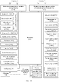
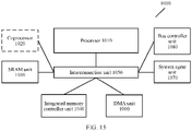
- a hardware structure of the control terminal 100 and an example of a software architecture of the control terminal 100 are described below with reference to FIG. 14 and FIG. 15 .
- a user may view a message on a display of the control terminal 100, or may access a message by using a speaker of the control terminal 100 or another output device.
- the user may view information on a display of a mobile phone, a smartwatch, or a smart band.
- a user may access a message by using a headset, a speaker, a haptic feedback apparatus, or the like that is coupled to the control terminal 100 or that is used as a part of the control terminal 100.
- a device discovery APP 101 may be installed on the control terminal 100.
- the device discovery APP 101 is configured to provide a network configuration guiding service.
- the device discovery APP 101 may also provide the network configuration guiding service in the two manners.
- the control terminal 100 may be used as an AP, and a smart device 300 is correspondingly used as a station (Station).
- the device discovery APP 101 may send a signal to a Wi-Fi unit 102 of the control terminal 100, to control the Wi-Fi unit to enable a hotspot, so that a user can find, by using the device discovery App, the smart device 300 that is in a station (Station) mode and that waits for network configuration.
- the smart device 300 may be used as an AP, and the control terminal 100 is used as a station (Station).
- the device discovery APP 101 sends a signal to the Wi-Fi unit 102 of the control terminal 100, to control the Wi-Fi unit 102 to enable Wi-Fi scanning, so that a user can find, by using the device discovery APP 101, the smart device 300 that is in an AP mode and that waits for network configuration.
- the control terminal 100 may establish a communication connection to the smart device 300 after confirmation of the user, access a cloud service of the smart device 300 by using a device ID and a cloud service address that are sent by the smart device 300, and install a device management APP 103 of a manufacturer after authorization of the user.
- the device management APP 103 is usually provided by a device manufacturer, and is configured to manage a smart device 300 of each manufacturer. Device management APPs 103 of different manufacturers may have different names.
- the device discovery APP 101 sends related network configuration authorization information to the device management APP 103.
- the device management APP 103 of the manufacturer establishes a communication connection to the smart device 300 through the Wi-Fi unit of the control terminal 100, and performs a subsequent network configuration process.
- the device management APP 103 may send a message indicating network configuration succeeds to the device discovery APP 101, so that the user can view, in the device discovery APP 101, the smart device 300 for which network configuration has been performed.
- the following describes a network configuration process according to an embodiment of this application in detail by using an example in which a mobile phone is used as the control terminal 100 and a home Wi-Fi hotspot is used as the wireless access point 400.
- the mobile phone may also be replaced with another control terminal, for example, a smart television or a smartwatch, and home Wi-Fi may also be replaced with another wireless network access point.
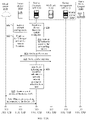
- a user opens a device discovery APP 311 of a mobile phone 310, and enables a device discovery function in the device discovery APP 311.
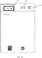
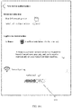
- FIG. 4A shows an example of an initial user interface (user interface, UI) of the device discovery APP 311.
- the initial UI of the device discovery APP 311 may include a device discovery mode selection box 403, a signal identifier 402, and an enable button 401.
- the device discovery APP 311 is initially in an initial state in which a mobile phone hotspot is not enabled.
- an indication indicating that the user enables the device discovery function may be received.
- the user indication may be received in a form of selecting a user interface element (for example, touching, tapping, selecting a user interface button on a screen, typing, an audio input, a gesture input, or the like).
- the user may tap the enable button 401 in FIG. 4A to enable the device discovery function, and select, by using the device discovery mode selection box 403, an AP mode or a station (station) mode of the mobile phone 310.
- an "AP" mode is selected in the device discovery mode selection box 403, so that when the mobile phone 310 communicates with a smart device 330 through a Wi-Fi protocol subsequently, the mobile phone 310 is used as an AP, and the smart device 330 is used as a station.
- the device discovery APP 311 After receiving an instruction for enabling device discovery, the device discovery APP 311 sends a signal to a Wi-Fi unit 312 of the mobile phone 310, to enable a Wi-Fi hotspot (no password required) of the mobile phone 310.
- the Wi-Fi unit 312 of the mobile phone 310 After receiving the instruction, the Wi-Fi unit 312 of the mobile phone 310 enables the Wi-Fi hotspot, and periodically sends a beacon broadcast frame to broadcast Wi-Fi hotspot information (for example, a service set identifier (Service Set Identifier, SSID)) of the mobile phone 310, so that the smart device 330 discovers and connects to a Wi-Fi network created by the mobile phone 310.
- a service set identifier Service Set Identifier, SSID
- FIG. 4B shows an example of a UI of the device discovery APP 311 in a case in which the device discovery APP 311 receives an enable instruction and the "AP" mode is selected.
- the user selects the "AP" mode in the device discovery mode selection box 403, and taps the enable button 401 of the mobile phone, so that the enable button 401 switches from a first state shown in FIG. 4A to a second state shown in FIG. 4B .
- a Wi-Fi hotspot of the mobile phone is enabled, and the signal identifier 402 in the UI may be be changed from a disabled state shown in FIG. 4A into an enabled state shown in FIG. 4B , that is, from a state with a disabled identifier (for example, ⁇ in FIG. 4A ) into a state without the disabled identifier shown in FIG. 4B .
- the signal identifier 402 may indicate the disabled state and the enabled state of a Wi-Fi hotspot in another manner. For example, being gray indicates that a Wi-Fi hotspot is not enabled, and being colored indicates that a Wi-Fi hotspot is enabled.
- S4 The smart device 330 enters a network configuration mode.
- a manner in which the smart device 330 enters the network configuration mode may be flexibly set by a manufacturer that provides the smart device 330.
- the manner may be set as follows: The smart device 330 enters the network configuration mode when being powered on for the first time, or the device enters the network configuration mode when a user resets the smart device 300 (for example, by pressing and holding a physical button on the device). After entering the network configuration mode, the smart device 330 works as a station (station). It may be understood that, in embodiments of this application, a sequence of performing the operation of S4 on the smart device 330 side and performing the operations of S1 to S3 on the mobile phone 310 side is not limited.
- an extension field in the probe request message may carry the following information: a waiting-for-network-configuration mark, a device ID, a device manufacturer ID, a name, a device type, a package name of a device management APP, a cloud service address of the device, a signature field generated by the device, and/or the like.
- the foregoing information does not need to be completely included in the probe request message.
- some of the information may be carried in the probe request message based on various conditions such as a storage capacity of the smart device 330. For example, in some embodiments, only the device ID and the cloud service address of the device may be carried.
- FIG. 11 shows an example of the extension field.
- the mobile phone 310 After receiving the probe request message sent by the smart device 330, the mobile phone 310 caches information of the smart device 330, and sends a probe response (Probe Response) message to the smart device 330.
- the probe response message may carry information indicating that network configuration is supported.
- association request an association request message to the mobile phone 310 while identity authentication is not required, to request to connect to the Wi-Fi network.
- S8 The mobile phone 310 responds to the association request of the smart device 330.
- the smart device 330 After operations of S5 to S8 are performed, authentication interaction of a Wi-Fi connection ends, the smart device 330 establishes a communication connection to the mobile phone 310, and then can normally perform data exchange.
- the smart device 330 may receive a plurality of probe response messages. In this case, the smart device 330 may preferentially connect to a newly-created Wi-Fi hotspot that carries information indicating that network configuration is supported.
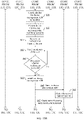
- the device discovery APP 311 After the device discovery APP 311 detects, by listening, that the smart device 330 has established a communication connection to the Wi-Fi hotspot of the mobile phone 310, the device discovery APP 311 may access a cloud server 320 of the smart device 330 based on the cloud service address that is of the smart device 330 and that is obtained in the Wi-Fi connection process, to obtain network configuration information required for network configuration of the smart device 330.
- the device discovery APP 311 may send a network configuration information obtaining request to the cloud server 320 by using a mobile communications function of the mobile phone 310, to request to obtain network configuration information required by the smart device 330 to connect to a home Wi-Fi hotspot 340.
- the cloud server 320 sends the network configuration information to the mobile phone 310 in response to the received network configuration information obtaining request sent by the mobile phone 310.
- the network configuration information may include but is not limited to: a device ID, a device MAC address, a device manufacturer ID, a device manufacturer name, a device type, information of a device management APP provided by a device manufacturer, a signature field generated by the device, and/or the like.
- a reason for accessing the cloud server 320 is mainly in consideration that the device side generally cannot store too much information. Therefore, a service on the cloud side may be accessed. When a storage capacity on the device side is large enough, related network configuration information may alternatively be directly obtained from the smart device 330.
- the device discovery APP 311 After obtaining the related network configuration information of the smart device 330, the device discovery APP 311 checks, based on the obtained information of the device management APP, whether a device management APP 313 provided by the manufacturer of the smart device 330 is installed on the mobile phone 310.
- the device discovery APP 311 selectively displays, to the user based on the obtained related network configuration information of the smart device 330, some information related to the smart device 330, for example, the device name and the information of a device management APP provided by a device manufacturer, and prompts the user to perform processing.
- the device discovery APP 311 may prompt the user to authorize the smart device 330 to connect to the network and install the device management APP 313 of the smart device 330.
- the device discovery APP 311 may prompt the user to authorize the smart device 330 to connect to the network.
- the mobile phone 310 is used as an AP, and the smart device 330 is used as a station. Therefore, one mobile phone 310 may be connected to a plurality of smart devices 330 at the same time.
- FIG. 5A and FIG. 5B respectively show a case in which the mobile phone 310 is connected to one device and a case in which the mobile phone 310 is connected to a plurality of smart devices.
- FIG. 5A shows a case in which the mobile phone 310 is connected to one smart device 330, that is, a "brand-A sweeping robot", in an AP mode.
- a device list 501 may be displayed in a UI of the device discovery APP 311, and some information 502 about the brand-A sweeping robot is displayed in the device list.
- the some information 502 of the brand-A sweeping robot may include a device name "brand-A sweeping robot" of the brand-A sweeping robot, a MAC address "7C-11-CB-54-67-F6" of the brand-A sweeping robot, a time point "12:30:10" at which the brand-A sweeping robot establishes a connection to the mobile phone 310, a name "A Home” of a device management APP corresponding to the brand-A sweeping robot, and the like.
- the UI may further display an "Authorize” button 505, to prompt the user to authorize installation of the device management APP "A Home” on the left, authorize the corresponding device to connect to a network, and the like.
- the information 502 that is displayed in the example UI and that is related to the brand-A sweeping robot is merely an example for description. In different embodiments, the example UI may display different information. This is not limited in this application.
- FIG. 5B shows a case in which the mobile phone 310 is connected to two smart devices 330 at the same time in an AP mode.
- the mobile phone 310 is connected to two smart devices, that is, a "brand-B desk lamp” and a "brand-A sweeping robot".
- a device list 501 may be displayed in a UI of the device discovery APP 311, and some information 502 of the "brand-A sweeping robot" and some information 503 of the "brand-B desk lamp” are displayed separately in the device list 501.
- the some information 502 of the brand-A sweeping robot may include a device name "brand-A sweeping robot" of the brand-A sweeping robot, a MAC address "7C-11-CB-54-67-F6" of the brand-A sweeping robot, a time point "12:30:10" at which the brand-A sweeping robot establishes a connection to the mobile phone 310, a name "A Home” of a device management APP corresponding to the brand-A sweeping robot, and the like.
- the some information 503 of the brand-B desk lamp may include a device name "brand-B desk lamp” of the brand-B desk lamp, a MAC address "7C-11-CB-54-67-F7" of the brand-B desk lamp, a time point "12:30:10" at which the brand-B desk lamp establishes a connection to the mobile phone 310, a name "B Home” of a device management APP corresponding to the brand-B desk lamp, and the like.
- the UI may further separately display an "Authorize” button 505 of "A Home” and an “Authorize” button 506 of "B Home”, to prompt the user to authorize installation of the device management APP "AHome” and/or the device management APP "B Home” on the left, authorize a corresponding device to connect to a network, and the like.
- the UI of the device discovery APP 311 may jump to FIG. 6 .
- the UI shown in FIG. 5A may be skipped, and the UI shown in FIG. 6 is directly displayed.
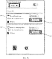
- FIG. 6 shows an example of a UI of the device discover APP 311 in which information is displayed to the user and the user is prompted for authorization when the device management APP 313 is not installed on the mobile phone 310.
- the device discovery APP 311 may display more detailed information related to the smart device 330 to the user, and prompt the user to authorize the smart device 330 to connect to a network and install the device management APP 313 of the smart device 330.
- the device discovery APP 311 displays, to the user, a name 601 "brand-A sweeping robot" of the smart device 330, a brief introduction 602 of the device management APP "A Home” corresponding to the "brand-A sweeping robot", a name 603 "home 1" of a wireless network to which the smart device 330 can connect, prompt information 605, and an "Authorize” button 606.
- the device discovery APP 311 may provide wireless network selection and switching options for the user, so that the user can select a Wi-Fi network (usually a home Wi-Fi network) to which the smart device 330 needs to connect for working.
- a Wi-Fi network usually a home Wi-Fi network
- the user may tap a selection identifier 604 in FIG. 6 to view names of all optional wireless networks, and select a wireless network to which the smart device 330 is to connect.
- the prompt information may no longer include prompt information for installing the device management APP 313.
- the prompt information 605 may no longer include prompt information indicating that installation of the "A Home" APP is allowed.
- the device discovery APP receives an input of the user for authorization.
- the user may perform authorization by clicking the "Authorize” button 606.
- the device discovery APP 311 may verify a user identity, for example, may require the user to enter a lock screen password or enter a fingerprint, and determine whether user verification succeeds.
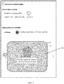
- FIG. 7 shows an example of a UI in which the device discovery APP 311 verifies the user identity by using a fingerprint. Based on the UI shown in FIG. 6 , a verification area 701 is overlaid, and the user is prompted in the verification area 701 to enter a fingerprint to confirm authorization.
- the verification area 701 may be disposed in a fingerprint sensing area, and is used to collect the fingerprint of the user to confirm the user identity.
- the user identity may be verified in various manners, for example, by prompting, in a UI of the device discovery APP 311, the user to enter a lock screen password or to enter iris information by keeping an eye close to the mobile phone 310an eye close to the mobile phone 310.
- the device discovery APP 311 may prompt the user to re-enter a screen lock password or re-enter a fingerprint, or perform verification again in another verification manner.
- a maximum quantity of verification times may be set. If a quantity of verification times of a user exceeds a preset threshold of a quantity of verification times, a network configuration process may be interrupted or stopped.
- S16 may be continuously performed: Downloading and installing the device management APP 313 starts, and the device discovery APP 311 automatically installs the device management APP 313 of the manufacturer in the background.
- FIG. 8A and FIG. 8B respectively show an example of a UI of the device discovery APP 311 in which the device discovery APP 311 downloads the device management APP and an example of a UI of the device discovery APP 311 in which the device discovery APP 311 prompts the user to install the device management APP.
- a download progress 801 of the device management APP 313 of the manufacturer may be displayed in the UI of the device discovery APP 311. After installation is completed, the download progress 801 may be changed into an "Install App" button 802, to prompt the user to install the App.
- S16 is optional. According to some embodiments of this application, when the device management APP 313 provided by the device manufacturer has been installed on the mobile phone 310, this step may be directly skipped.
- the device discovery APP 311 may prompt the user to open the device management APP 313, and notify the device management APP 313 that there is a device waiting for network configuration currently.
- the "Install App” button 802 in the UI of the device discovery APP 311 shown in FIG. 8B may be changed into an "Open App” button 901 shown in FIG. 9 , so that the user can tap the "Open App” button 901 to open the device management APP 313.
- the device management APP 313 may first guide the user to register or login in. The operation is optional, and whether registration or login is required may be determined by the device manufacturer.
- the device management APP 313 may query network configuration authorization information from the device discovery APP 311.
- the device discovery APP 311 may provide an application program interface (Application Program Interface, API) for the smart device 330 to query the network configuration authorization information.
- API Application Program Interface
- the network configuration authorization information may include but is not limited to: an authorization ID, a device ID, a device MAC address, an IP of the device on current Wi-Fi, a signature field generated by the smart device 330, network information (for example, a service set identifier (Service Set Identifier, SSID) and a password of a wireless network) of a wireless network to which the smart device 330 is to connect, and the like.
- Some of the network configuration authorization information may come from the network configuration information obtained by the device discovery APP 311 from the cloud server 320 or the smart device 330, and some of the network configuration authorization information is generated and stored in the mobile phone 310.
- the device management APP 313 may need to integrate a software development kit (Software Development Kit, SDK) provided by the device discovery APP 311.
- the device discovery APP 311 sends, to the device management APP 313, device network configuration authorization information that can be accessed by the device management APP 313.
- the device management APP 313 can access only network configuration authorization information of a smart device 330 that belongs to a brand of the device management APP 313.
- the device management APP 313 of the manufacturer may verify the network configuration authorization information. This operation is also an optional operation, and may be designed and determined by the device manufacturer. The device management APP 313 may perform verification based on a field generated during network configuration of the device and corresponding signature information.
- the device management APP 313 may communicate with the smart device 330 based on the Wi-Fi hotspot of the mobile phone 310, and notify the smart device 330 to switch a network.
- a network switching notification message is exchanged to the smart device 330 in a unicast manner.
- the device management APP 313 may send the message to the smart device 330 in a UDP protocol unicast manner, a TCP protocol unicast manner, or the like. In this way, a password of the home Wi-Fi hotspot 340 does not need to be broadcast, thereby improving security of a network configuration process.
- the smart device 330 disconnects from the Wi-Fi hotspot of the mobile phone based on the received network switching notification message, and connects to the home Wi-Fi hotspot 340 based on the SSID and the password that are of the to-be-connected wireless network (that is, the home Wi-Fi) and that are included in the received network switching notification message.
- the cloud server 320 of the smart device 330 may notify the device management APP 313 that network configuration of the smart device 330 succeeds.
- the device management APP 313 After receiving a message sent by the cloud server 320, the device management APP 313 sends a message to the device discovery APP 311, to notify the device discovery APP 311 that network configuration of the smart device 330 succeeds. In addition, the device management APP 313 may prompt the user that network configuration succeeds, for example, prompt the user by using a sound or a UI change.
- the device discovery APP 311 may update the UI, to prompt the user that network configuration of the smart device 330 succeeds, or prompt the user that configuration of a next smart device can be continued, or the like.
- a UI of the device discovery APP 311 may return to a device list, as shown in FIG. 10 . In this way, the user can perform configuration of a next device "brand-B desk lamp".
- the device discovery APP 311 can automatically disable the Wi-Fi hotspot of the mobile phone.
- the device discovery APP 311 is provided to guide the user to install the device management APP 313 provided by the manufacturer of the smart device 330
- the device network configuration assistance API is provided to be invoked by the device management APP 313 of the manufacturer, to assist the device management APP 313 of the manufacturer in completing the network configuration of the device.
- an identity authentication capability of the mobile phone is used, for example, a fingerprint or a screen lock password is used to confirm a current user identity, thereby simplifying an operation of authorizing the smart device 330 to connect to the home Wi-Fi hotspot 340.
- the smart device 330 can be discovered by the device discovery APP 311 provided that the smart device 330 marks device information of the smart device 330 in the Wi-Fi protocol. Therefore, the user is guided to install the device management APP 313 of the manufacturer, and the device management APP 313 of the manufacturer is used for network configuration, which is also compatible.
- the user when performing network configuration of smart devices, the user does not need to search for and install each corresponding device management APP 313 for each smart device 330. Instead, the user can directly use a general APP such as the device discovery APP 311 to automatically search for and install each corresponding device management APP 313, thereby facilitating and simplifying a network configuration operation for the smart device.
- a general APP such as the device discovery APP 311 to automatically search for and install each corresponding device management APP 313, thereby facilitating and simplifying a network configuration operation for the smart device.
- the user may directly open the device management APP 313 without performing an authorization operation before opening the device management APP 313.
- a network configuration process is interrupted after the user installs the device management APP 313 of the manufacturer, and subsequently, the user opens the device management APP 311 again to continue to perform a network configuration operation.
- the user may be directly prompted to open the APP.
- the authorization operations of S13 to S16 in FIG. 3B are skipped, S17 is directly performed to match and jump to the installed device management APP 313 of the device manufacturer.
- some embodiments in which a smart device is in a station mode and a mobile phone is used as an AP are provided.
- some smart devices support network configuration only in an AP mode.
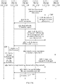
- S50 A user opens a device discovery APP 1311 of a mobile phone 1310, and enables a device discovery function in the device discovery APP 1311.
- An initial user interface of the device discovery APP 1311 may still be referred to that shown in FIG. 4A .
- the device discovery APP 1311 is in an initial state in which a mobile phone hotspot is not enabled.
- an indication indicating that the user enables the device discovery function may be received.
- the user indication may be received in a form of selecting a user interface element (for example, touching, tapping, selecting a user interface button on a screen, typing, an audio input, a gesture input, or the like).
- the user may tap the enable button 401 in FIG. 4A to enable the device discovery function.
- the user selects a "station" mode in the device discovery mode selection box 403, so that when the mobile phone 1310 communicates with a smart device 1330 through a Wi-Fi protocol subsequently, the mobile phone 1310 is used as a station, and the smart device 1330 is used as an AP.
- the device discovery APP 1311 After receiving an instruction for enabling device discovery, the device discovery APP 1311 sends a message to a Wi-Fi unit 1312 of the mobile phone 1310, to instruct the Wi-Fi unit 1312 of the mobile phone 1310 to start scanning a surrounding Wi-Fi signal.
- FIG. 4C shows an example of a UI of the device discovery APP 1311 in a case in which the device discovery APP 1311 receives an enable instruction and the "station" mode is selected.
- the user selects the "station" mode in the device discovery mode selection box 403, and taps the enable button 401 of the mobile phone, so that the enable button 401 switches from a first state shown in FIG. 4A to a second state shown in FIG. 4C .
- the Wi-Fi unit 1312 of the mobile phone disconnects from an originally connected Wi-Fi hotspot, and starts to scan the surrounding Wi-Fi hotspot, and the signal identifier 402 in the UI may be changed from a disabled state shown in FIG. 4A into an enabled state shown in FIG.
- the signal identifier 402 may indicate the disabled state and the enabled state in another manner. For example, being gray indicates the disabled state, and being colored indicates the enabled state.
- the smart device 1330 enters a network configuration mode.
- a manner in which the smart device 1330 enters the network configuration mode may also be flexibly set by a manufacturer that provides the smart device 1330.
- the manner may be set as follows: The smart device 1330 enters the network configuration mode when being powered on for the first time, or the device enters the network configuration mode when a user resets the smart device 300 (for example, by pressing and holding a physical button on the device). After entering the network configuration mode, the smart device 1330 works as the AP.
- the smart device 1330 After entering the network configuration state as the AP, the smart device 1330 enables a Wi-Fi hotspot, and periodically sends a beacon broadcast frame, to broadcast Wi-Fi hotspot information (for example, an SSID) of the smart device 1330, so that the mobile phone 1310 discovers and connects to a Wi-Fi network established by the smart device 1330.
- Wi-Fi hotspot information for example, an SSID
- a sequence of performing operations of S53 and S54 on the smart device 1330 side and performing the operations of S51 and S52 on the mobile phone 1310 side is not limited.
- the Wi-Fi unit 1312 of the mobile phone 1310 needs to first disconnect from the currently connected Wi-Fi hotspot, and then send a probe request (Probe Request) to scan the surrounding Wi-Fi signal.
- the probe request message sent by the mobile phone 1310 may carry information indicating that network configuration is supported.
- the probe request message may alternatively not carry information indicating that network configuration is supported.
- an extension field in the probe response message may carry the following information: a waiting-for-network-configuration mark, a device ID, a device manufacturer ID, a name, a device type, a package name of a device management APP, a cloud service address of the device, a signature field generated by the device, and/or the like.
- the foregoing information does not need to be completely included in the probe response message.
- some of the information may be carried in the probe response message based on various conditions such as a storage capacity of the smart device 1330. For example, in some embodiments, only the device ID and the cloud service address of the device may be carried.
- a Wi-Fi hotspot with a waiting-for-network-configuration mark may be listed in a UI of the device discovery APP 1311 for the user to select.
- the mobile phone 1310 is used as a station, and the smart device 1330 is used as an AP. Therefore, one mobile phone 1310 can be connected to only one smart device 1330.
- a device list may be displayed in a UI of the device discovery APP 1311, and Wi-Fi information of one or more smart devices 1330 is displayed in the device list.
- SSIDs of two smart devices 1330 are listed in the device list in the UI of the device discovery APP 1311: a "brand-A sweeping robot" and a "brand-B desk lamp", and some information 507 of the "brand-A sweeping robot” and some information 508 of the "brand-B desk lamp” are displayed separately.
- the some information 507 of the brand-A sweeping robot may include an SSID "brand-A sweeping robot" of the brand-A sweeping robot, a MAC address "7C-11-CB-54-67-F6" of the brand-A sweeping robot, a name "A Home” of a device management APP corresponding to the brand-A sweeping robot, and the like.
- the some information 508 of the brand-B desk lamp may include an SSID "brand-B desk lamp” of the brand-B desk lamp, a MAC address "7C-11-CB-54-67-F7" of the brand-B desk lamp, a name "B Home” of a device management APP corresponding to the brand-B desk lamp, and the like.
- the UI may further separately display an "Authorize” button 509 of "A Home” and an “Authorize” button 510 of "B Home”, to prompt the user to authorize installation of the device management APP "A Home” and/or the device management APP "B Home” on the left, authorize a corresponding device to connect to a network, and the like.
- the mobile phone 1310 does not establish a communication connection to any smart device 1330, and the user may tap the "Authorize” button 509 to select one of two Wi-Fi hotspots to perform an operation.
- the device discovery APP 1311 may have performed configuration of another smart device, and a smart device that has been configured may also be displayed in the device list. For example, as shown in FIG. 5D , some information 511 of a smart device "brand-C refrigerator" that has been configured before and the some information 507 that is of a Wi-Fi hotspot "brand-A sweeping robot" with a waiting-for-network-configuration mark that is newly scanned by the mobile phone 1310 are separately displayed in the device list 501.
- the device discovery APP 1311 detects that the waiting-for-network-configuration mark exists in the received probe response messagethe received probe response message, and the device discovery APP 1311 may access a cloud server 1320 of the smart device 1330 based on the cloud service address of the smart device 1330 in the probe response message, to obtain network configuration information required for network configuration of the smart device 1330.
- the device discovery APP 1311 may send a network configuration information obtaining request to the cloud server 1320 by using a mobile communications function of the mobile phone 1310, to request to obtain network configuration information required by the smart device 1330 to connect to a home Wi-Fi hotspot 1340.
- the cloud server 1320 sends the network configuration information to the mobile phone 1310 in response to the received network configuration information obtaining request sent by the mobile phone 1310.
- the network configuration information may include but is not limited to: a device ID, a device MAC address, a device manufacturer ID, a device manufacturer, a device type, information of a device management APP provided by the device manufacturer, a signature field generated by the device, and/or the like.
- a reason for accessing the cloud server 1320 is mainly in consideration that the device side generally cannot store too much information. Therefore, a service on the cloud side may be accessed. When a storage capacity on the device side is large enough, related network configuration information may alternatively be directly obtained from the smart device 1330. According to some embodiments of this application, operations of the two steps S57 and S58 may be performed before the operation of S56 or may be performed in parallel with the operation of S56.
- the device discovery APP 1311 checks, based on the obtained information of the device management APP, whether a device management APP 1313 provided by the manufacturer of the smart device 1330 is installed on the mobile phone 1310.
- the device discovery APP 1311 selectively displays, to the user based on the obtained related network configuration information of the smart device 1330, some information related to the smart device 1330, for example, the device name and the information of a device management APP provided by a device manufacturer, and prompts the user to perform processing.
- the device discovery APP 1311 may prompt the user to authorize the smart device 1330 to connect to the network and install the device management APP 1313 of the smart device 1330.
- the device discovery APP 1311 may prompt the user to authorize the smart device 1330 to connect to the network.
- the UI of the device discovery APP 1311 may jump to FIG. 6 .
- FIG. 6 shows an example of a UI that is used when the device management APP 1313 is not installed on the mobile phone 1310.
- the device discovery APP 1311 may display detailed information related to the smart device 1330 to the user, and prompt the user to authorize the smart device 1330 to connect to a network and install the device management APP 1313 of the smart device 1330.
- the device discovery APP 1311 displays, to the user, a name 601 "brand-A sweeping robot" of the smart device 1330, a brief introduction 602 of the device management APP "A Home” corresponding to the "brand-A sweeping robot", a name 603 "home 1" of a wireless network to which the smart device 1330 can connect, prompt information 605, and an "Authorize” button 606.
- the device discovery APP 1311 may provide wireless network selection and switching options for the user, so that the user can select a Wi-Fi network (usually a home Wi-Fi network) to which the smart device 1330 needs to connect for working.
- a Wi-Fi network usually a home Wi-Fi network
- the user may tap a selection identifier 604 in FIG. 6 to view names of all optional wireless networks, and select a wireless network to which the smart device 1330 is to connect.
- the prompt information may no longer include prompt information for installing the device management APP 1313.
- the prompt information 605 may no longer include prompt information indicating that installation of the "A Home" APP is allowed.
- the device discovery APP receives an input of the user for authorization.
- the user may perform authorization by clicking the "Authorize” button 606.
- the device discovery APP 1311 may verify a user identity, for example, may require the user to enter a lock screen password or enter a fingerprint, and determine whether user verification succeeds.
- FIG. 7 shows an example of a UI in which the device discovery APP 1311 verifies the user identity by using a fingerprint. Based on the UI shown in FIG. 6 , a verification area 701 is overlaid, and the user is prompted in the verification area 701 to enter a fingerprint to confirm authorization.
- the verification area 701 may be disposed in a fingerprint sensing area, and is used to collect the fingerprint of the user to confirm the user identity.
- the user identity may be verified in various manners, for example, by prompting, in a UI of the device discovery APP 1311, the user to enter a lock screen password or to enter iris information by keeping an eye close to the mobile phone 1310eye close to the mobile phone 1310.
- the device discovery APP 1311 may prompt the user to re -enter a screen lock password or re-enter a fingerprint, or perform verification again in another verification manner.
- a maximum quantity of verification times may be set. If a quantity of verification times of a user exceeds a preset threshold of a quantity of verification times, a network configuration process may be interrupted or stopped.
- S64 may be continuously performed: Installing the device management APP 1313 starts, and the device discovery APP 1311 installs the device management APP 1313 of the manufacturer in the background.
- An example of a UI of the device discovery APP 1311 in which the device discovery APP 1311 downloads the device management APP and an example of a UI of the device discovery APP 1311 in which the device discovery APP 1311 prompts the user to install the device management APP may still be referred to FIG. 8A and FIG. 8B .
- a download progress 801 of the device management APP 1313 of the manufacturer may be displayed in the UI of the device discovery APP 1311. After installation is completed, the download progress 801 may be changed into an "Install App" button 802, to prompt the user to install the App.
- S64 is optional. According to some embodiments of this application, when the device management APP 1313 provided by the device manufacturer has been installed on the mobile phone 1310, this step may be directly skipped.
- the device discovery APP 1311 may prompt the user to open the device management APP 1313, and notify the device management APP 1313 that there is a device waiting for network configuration currently.
- the "Install App” button 802 in the UI of the device discovery APP 1311 shown in FIG. 8B may be changed into an "Open App” button 901 shown in FIG. 9 , so that the user can tap the "Open App” button 901 to open the device management APP 1313.
- the device management APP 1313 may first guide the user to register or login in. The operation is optional, and whether registration or login is required may be determined by the device manufacturer.
- the device management APP 1313 may query network configuration authorization information from the device discovery APP 1311.
- the device discovery APP 1311 may provide an application program interface (Application Program Interface, API) for the smart device 1330 to query the network configuration authorization information.
- API Application Program Interface
- the network configuration authorization information may include but is not limited to: an authorization ID, a device ID, a device MAC address, an IP of the device on current Wi-Fi, a signature field generated by the smart device 1330, network information (for example, an SSID and a password of a wireless network) of a wireless network to which the smart device 1330 is to connect, and the like.
- Some of the network configuration authorization information may come from the network configuration information obtained by the device discovery APP 1311 from the cloud server 1320 or the smart device 1330, and some of the network configuration authorization information is generated and stored in the mobile phone 1310.
- the device management APP 1313 may need to integrate a software development kit (Software Development Kit, SDK) provided by the device discovery APP 1311.
- the device discovery APP 1311 sends, to the device management APP 1313, device network configuration authorization information that can be accessed by the device management APP 1313.
- the device management APP 1313 can access only network configuration authorization information of a smart device 1330 that belongs to a brand of the device management APP 1313.
- the device management APP 1313 of the manufacturer may verify the network configuration authorization information. This operation is also an optional operation, and may be designed and determined by the device manufacturer. The device management APP 1313 may perform verification based on a field generated during network configuration of the device and corresponding signature information.
- the device discovery APP 1311 After the verification performed by the device management APP 1313 on the related information succeeds, the device discovery APP 1311 sends an association request (association request) message to the smart device 1330 to request to connect to a Wi-Fi hotspot of the smart device 1330.
- association request association request
- S71 The smart device 1330 responds to the association request of the mobile phone 1310.
- the mobile phone 1310 after the mobile phone 1310 and the smart device 1330 discover each other, the mobile phone 1310 does not immediately connect to the Wi-Fi hotspot of the smart device 1330, but first performs operations such as the authorization and the verification, and then connects to the Wi-Fi hotspot of the smart device 1330 after the device management APP 1313 is downloaded.
- the device management APP 1313 is first downloaded and then the smart device 1330 establishes the communication connection to the mobile phone 1310, so that the mobile phone 1310 can be prevented from frequently switching networks.
- the mobile phone 1310 may alternatively first connect to the Wi-Fi hotspot of the smart device 1330, and then perform operations such as the authorization and the verification.
- the mobile phone 1310 switches to a Wi-Fi network for daily work of the mobile phone 1310 or a mobile network provided by an operator. After the download is completed, the mobile phone 1310 re-switches to the Wi-Fi hotspot of the smart device 1330.
- the device discovery APP 1311 After the smart device 1330 establishes the communication connection to the mobile phone 1310, the device discovery APP 1311 notifies the device management APP 1313 that the device management APP 1313 can communicate with the smart device 1330.
- the device management APP 1313 communicates with the smart device 1330 based on a Wi-Fi communications protocol between the smart device 1330 and the mobile phone 1310, and notify the smart device 1330 to switch a network.
- a network switching notification message is exchanged to the smart device 1330 in a unicast manner by using a UDP protocol or the like. In this way, a password of the home Wi-Fi hotspot 1340 does not need to be broadcast, thereby improving security of a network configuration process.
- the smart device 1330 disables the Wi-Fi hotspot of the smart device 1330 based on the received network switching notification message, and connects to the home Wi-Fi hotspot 1340 based on the SSID and the password that are of the to-be-connected wireless network (that is, the home Wi-Fi) and that are included in the received network switching notification message.
- the smart device 1330 After establishing a communication connection to the home Wi-Fi hotspot 1340, the smart device 1330 sends, to the cloud server 1320 of the device, a message indicating that network configuration of the device succeeds.
- the mobile phone 1310 may automatically connect to an originally connected Wi-Fi hotspot, for example, the home Wi-Fi hotspot 1340.
- the mobile phone 1310 may also disable Wi-Fi.
- the cloud server 1320 of the smart device 1330 may notify the device management APP 1313 that network configuration of the smart device 1330 succeeds.
- the device management APP 1313 After receiving a message sent by the cloud server 1320, the device management APP 1313 sends a message to the device discovery APP 1311, to notify the device discovery APP 1311 that network configuration of the smart device 1330 succeeds. In addition, the device management APP 1313 may prompt the user that network configuration succeeds, for example, prompt the user by using a sound or a UI change.
- the device discovery APP 1311 may update the UI, to prompt the user that network configuration of the smart device 1330 succeeds, or prompt the user that configuration of a next smart device can be continued, or the like.
- a UI of the device discovery APP 1311 may return to a device list, to prompt the user that configuration of a next device "brand-B desk lamp” can be performed.
- the device discovery APP 1311 is also provided to guide the user to install the device management APP 1313 provided by the manufacturer of the smart device 1330, to complete the network configurationnetwork configuration of the device.
- the user may directly open the device management APP 1313 without performing an authorization operation before opening the device management APP 1313.
- a network configuration process is interrupted after the user installs the device management APP 1313 of the manufacturer, and subsequently, the user opens the device management APP 1311 again to continue to perform a network configuration operation.
- some information related to the smart device 1330 for example, the device name and the information that is of the device management APP and that is provided by the manufacturer, is directly displayed for the user in the operation of S60, and the user is prompted to open the App.
- the operations of S61 to S64 in FIG. 13B are skipped, S65 is directly performed, to match and jump to the installed device management APP 1313 of the device manufacturer.
- a device discovery APP 311 is also provided to guide the user to install the device management APP 313 provided by the manufacturer of the smart device 330, and the device network configuration assistance API is provided to be invoked by the device management APP 313 of the manufacturer, to assist the device management APP 313 of the manufacturer in completing the network configuration of the device, thereby simplifying an operation of authorizing the smart device 330 to connect to the home Wi-Fi hotspot 340.
- the user when performing network configuration of smart devices, the user also does not need to search for and install each corresponding device management APP 313 for each smart device 330, but can directly use a general APP such as the device discovery APP 311 to automatically search for and install each corresponding device management APP 313, thereby facilitating and simplifying a network configuration operation for the smart device.
- a general APP such as the device discovery APP 311 to automatically search for and install each corresponding device management APP 313, thereby facilitating and simplifying a network configuration operation for the smart device.
- interfaces provided for the user are similar, so that the user can conveniently complete an entire network configuration process by performing very intuitive and simple operations.
- FIG. 14 is a schematic diagram of a structure of a control terminal 100 according to an embodiment of this application.
- the control terminal 100 may include a processor 110, an external memory interface 120, an internal memory 121, a universal serial bus (universal serial bus, USB) port 130, a charging management module 140, a power management module 141, a battery 142, an antenna 1, an antenna 2, a mobile communications module 150, a wireless communications module 160, an audio module 170, a speaker 170A, a receiver 170B, a microphone 170C, a headset jack 170D, a sensor module 180, a button 190, a motor 191, an indicator 192, a camera 193, a display 194, a subscriber identification module (subscriber identification module, SIM) card interface 195, and the like.
- a processor 110 an external memory interface 120, an internal memory 121, a universal serial bus (universal serial bus, USB) port 130, a charging management module 140, a power management module 141, a battery 142, an antenna 1, an antenna 2, a mobile communications module 150, a wireless communications module 160, an audio module 170,
- the sensor module 180 may include a pressure sensor 180A, a gyro sensor 180B, a barometric pressure sensor 180C, a magnetic sensor 180D, an acceleration sensor 180E, a distance sensor 180F, an optical proximity sensor 180G, a fingerprint sensor 180H, a temperature sensor 180J, a touch sensor 180K, an ambient light sensor 180L, a bone conduction sensor 180M, and the like.
- control terminal 100 may include more or fewer components than those shown in the figure, or may combine some components, or may split some components, or may have different component arrangements.
- the components shown in the figure may be implemented by hardware, software, or a combination of software and hardware.
- the processor 110 may include one or more processing units.
- the processor 110 may include an application processor (application processor, AP), a modem processor, a graphics processing unit (graphics processing unit, GPU), an image signal processor (image signal processor, ISP), a controller, a video codec, a digital signal processor (digital signal processor, DSP), a baseband processor, and/or a neural-network processing unit (neural-network processing unit, NPU), and/or the like.
- Different processing units may be independent components, or may be integrated into one or more processors.
- the controller may generate an operation control signal based on instruction operation code and a time sequence signal, to complete control of instruction reading and instruction execution.
- a memory may be further disposed in the processor 110, and is configured to store instructions and data.
- the memory in the processor 110 is a cache.
- the memory may store instructions or data just used or cyclically used by the processor 110. If the processor 110 needs to use the instructions or the data again, the processor 110 may directly invoke the instructions or the data from the memory. This avoids repeated access, and reduces waiting time of the processor 110, so that system efficiency is improved.
- the processor 110 may include one or more interfaces.
- the interface may include an inter-integrated circuit (inter-integrated circuit, I2C) interface, an inter-integrated circuit sound (inter-integrated circuit sound, I2S) interface, a pulse code modulation (pulse code modulation, PCM) interface, a universal asynchronous receiver/transmitter (universal asynchronous receiver/transmitter, UART) interface, a mobile industry processor interface (mobile industry processor interface, MIPI), a general-purpose input/output (general-purpose input/output, GPIO) interface, a subscriber identity module (subscriber identity module, SIM) interface, a universal serial bus (universal serial bus, USB) interface, and/or the like.
- I2C inter-integrated circuit
- I2S inter-integrated circuit sound
- PCM pulse code modulation
- PCM pulse code modulation
- UART universal asynchronous receiver/transmitter
- MIPI mobile industry processor interface
- GPIO general-purpose input/output
- the interface connection relationship between modules shown in this embodiment of this application is merely an example for description, and does not constitute a structural limitation on the control terminal 100.
- the control terminal 100 may alternatively use an interface connection manner different from that in the foregoing embodiment, or a combination of a plurality of interface connection manners.
- the charging management module 140 is configured to receive a charging input from a charger.
- the power management module 141 is configured to connect the battery 142 and the charging management module 140 to the processor 110.
- the power management module 141 receives an input from the battery 142 and/or the charging management module 140, and supplies power to the processor 110, the internal memory 121, the display 194, the camera 193, the wireless communications module 160, and the like.
- the power management module 141 may be further configured to monitor parameters such as a battery capacity, a battery cycle count, and a battery health status (electric leakage or impedance).
- the power management module 141 may alternatively be disposed in the processor 110.
- the power management module 141 and the charging management module 140 may alternatively be disposed in a same device.
- a wireless communication function of the control terminal 100 may be implemented by using the antenna 1, the antenna 2, the mobile communications module 150, the wireless communications module 160, the modem processor, the baseband processor, and the like.
- the antenna 1 and the antenna 2 are configured to transmit and receive electromagnetic wave signals.
- Each antenna in the control terminal 100 may be configured to cover one or more communications frequency bands. Different antennas may be further multiplexed, to improve antenna utilization.
- the antenna 1 may be multiplexed as a diversity antenna in a wireless local area network. In some other embodiments, the antenna may be used in combination with a tuning switch.
- the mobile communications module 150 may provide a solution, applied to the control terminal 100, to wireless communication including 2G, 3G, 4G, 5G, and the like.
- the mobile communications module 150 may include at least one filter, a switch, a power amplifier, a low noise amplifier (low noise amplifier, LNA), and the like.
- the mobile communications module 150 may receive an electromagnetic wave through the antenna 1, perform processing such as filtering and amplification on the received electromagnetic wave, and transmit a processed electromagnetic wave to the modem processor for demodulation.
- the mobile communications module 150 may further amplify a signal modulated by the modem processor, and convert the signal into an electromagnetic wave for radiation through the antenna 1.
- at least some function modules of the mobile communications module 150 may be disposed in the processor 110.
- at least some function modules of the mobile communications module 150 may be disposed in a same device as at least some modules of the processor 110.
- the modem processor may include a modulator and a demodulator.
- the modulator is configured to modulate a to-be-sent low-frequency baseband signal into a medium-high frequency signal.
- the demodulator is configured to demodulate a received electromagnetic wave signal into a low-frequency baseband signal. Then, the demodulator transmits the low-frequency baseband signal obtained through demodulation to the baseband processor for processing.
- the low-frequency baseband signal is processed by the baseband processor, and then transmitted to the application processor.
- the application processor outputs a sound signal through an audio device (which is not limited to the speaker 170A, the receiver 170B, or the like), or displays an image or a video by using the display 194.
- the modem processor may be an independent device.
- the modem processor may be independent of the processor 110, and is disposed in a same device as the mobile communications module 150 or another functional module.
- the wireless communications module 160 may provide a solution, applied to the control terminal 100, to wireless communication including a wireless local area network (wireless local area network, WLAN) (for example, a wireless fidelity (wireless fidelity, Wi-Fi) network), Bluetooth (Bluetooth, BT), a global navigation satellite system (global navigation satellite system, GNSS), frequency modulation (frequency modulation, FM), a near field communication (near field communication, NFC) technology, an infrared (infrared, IR) technology, or the like.
- the wireless communications module 160 may be one or more components integrating at least one communications processing module.
- the wireless communications module 160 receives an electromagnetic wave through the antenna 2, performs frequency modulation and filtering processing on an electromagnetic wave signal, and sends a processed signal to the processor 110.
- the wireless communications module 160 may further receive a to-be-sent signal from the processor 110, perform frequency modulation and amplification on the signal, and convert a processed signal into an electromagnetic wave for radiation through the antenna 2.
- the antenna 1 is coupled to the mobile communications module 150, and the antenna 2 is coupled to the wireless communications module 160, so that the control terminal 100 can communicate with a network and another device by using a wireless communications technology.
- the wireless communications technology may include a global system for mobile communications (global system for mobile communications, GSM), a general packet radio service (general packet radio service, GPRS), code division multiple access (code division multiple access, CDMA), wideband code division multiple access (wideband code division multiple access, WCDMA), time-division code division multiple access (time-division code division multiple access, TD-SCDMA), long term evolution (long term evolution, LTE), BT, a GNSS, a WLAN, NFC, FM, an IR technology, and/or the like.
- GSM global system for mobile communications
- GPRS general packet radio service
- code division multiple access code division multiple access
- CDMA wideband code division multiple access
- WCDMA wideband code division multiple access
- time-division code division multiple access time-division code
- the GNSS may include a global positioning system (global positioning system, GPS), a global navigation satellite system (global navigation satellite system, GLONASS), a BeiDou navigation satellite system (BeiDou navigation satellite system, BDS), a quasi-zenith satellite system (quasi-zenith satellite system, QZSS), and/or a satellite-based augmentation system (satellite-based augmentation systems, SBAS).
- GPS global positioning system
- GLONASS global navigation satellite system
- BeiDou navigation satellite system BeiDou navigation satellite system
- BDS BeiDou navigation satellite system
- QZSS quasi-zenith satellite system
- SBAS satellite-based augmentation system
- the control terminal 100 implements a display function by using the GPU, the display 194, the application processor, and the like.
- the display 194 is configured to display an image, a video, or the like.
- the display 194 includes a display panel.
- the display panel may be a liquid crystal display (liquid crystal display, LCD), an organic light-emitting diode (organic light-emitting diode, OLED), an active-matrix organic light-emitting diode (active-matrix organic light-emitting diode, AMOLED), a flexible light-emitting diode (flexible light-emitting diode, FLED), a mini-LED, a micro-LED, a micro-OLED, quantum dot light-emitting diodes (quantum dot light-emitting diodes, QLED), or the like.
- the control terminal 100 may include one or N displays 194, where N is a positive integer greater than 1.
- the control terminal 100 may implement a photographing function through the ISP, the camera 193, the video codec, the GPU, the display 194, the application processor, and the like.
- the external memory interface 120 may be configured to connect to an external memory card such as a micro SD card, to extend a storage capacity of the control terminal 100.
- the external memory card communicates with the processor 110 through the external memory interface 120, to implement a data storage function. For example, files such as music and a video are stored in the external memory card.
- the internal memory 121 may be configured to store computer-executable program code.
- the executable program code includes instructions.
- the internal memory 121 may include a program storage area and a data storage area.
- the program storage area may store an operating system, an application required by at least one function (for example, a voice playing function or an image playing function), and the like.
- the data storage area may store data (for example, audio data or an address book) created in a process of using the control terminal 100, and the like.
- the internal memory 121 may include a high-speed random access memory, or may include a nonvolatile memory such as at least one magnetic disk storage device, a flash memory, or a universal flash storage (universal flash storage, UFS).
- the processor 110 executes various functional applications and data processing of the control terminal 100 by running the instructions stored in the internal memory 121 and/or the instructions stored in the memory disposed in the processor.
- the control terminal 100 may implement an audio function, for example, music playing and recording, by using the audio module 170, the speaker 170A, the receiver 170B, the microphone 170C, the headset jack 170D, the application processor, and the like.
- an audio function for example, music playing and recording
- the audio module 170 is configured to convert digital audio information into an analog audio signal output, and is also configured to convert an analog audio input into a digital audio signal.
- the audio module 170 may be further configured to: code and decode an audio signal.
- the audio module 170 may be disposed in the processor 110, or some functional modules of the audio module 170 are disposed in the processor 110.
- the speaker 170A also referred to as a "loudspeaker" is configured to convert an audio electrical signal into a sound signal.
- the control terminal 100 may be used to listen to music or answer a call in a hands-free mode over the speaker 170A.
- the receiver 170B also referred to as an "earpiece", is configured to convert an audio electrical signal into a sound signal.
- the receiver 170B may be put close to a human ear to listen to a voice.
- the microphone 170C also referred to as a "mike” or a “mic”, is configured to convert a sound signal into an electrical signal.
- a user may make a sound by moving a human mouth close to the microphone 170C to input a sound signal to the microphone 170C.
- At least one microphone 170C may be disposed in the control terminal 100.
- two microphones 170C may be disposed in the control terminal 100, to collect a sound signal and further implement a noise reduction function.
- three, four, or more microphones 170C may be disposed in the control terminal 100, to collect a sound signal, reduce noise, identify a sound source, implement a directional recording function, and the like.
- the headset jack 170D is configured to connect to a wired headset.
- the headset jack 170D may be a USB port 130, or may be a 3.5 mm open mobile terminal platform (open mobile terminal platform, OMTP) standard interface or cellular telecommunications industry association of the USA (cellular telecommunications industry association of the USA, CTIA) standard interface.
- the fingerprint sensor 180H is configured to collect a fingerprint.
- the control terminal 100 may use a feature of the collected fingerprint to implement fingerprint-based unlocking, application lock access, fingerprint-based photographing, fingerprint-based call answering, and the like.
- the touch sensor 180K is also referred to as a "touch component”.
- the touch sensor 180K may be disposed on the display 194, and the touch sensor 180K and the display 194 constitute a touchscreen, which is also referred to as a "touchscreen”.
- the touch sensor 180K is configured to detect a touch operation performed on or near the touch sensor 180K.
- the touch sensor may transfer the detected touch operation to the application processor, to determine a type of a touch event.
- a visual output related to the touch operation may be provided on the display 194.
- the touch sensor 180K may alternatively be disposed on a surface of the control terminal 100 at a location different from that of the display 194.
- the button 190 includes a power button, a volume button, and the like.
- the button 190 may be a mechanical button, or may be a touch button.
- the control terminal 100 may receive a button input, and generate a key signal input related to a user setting and function control of the control terminal 100.
- the motor 191 may generate a vibration prompt.
- the motor 191 may be configured to provide an incoming call vibration prompt and a touch vibration feedback.
- touch operations performed on different applications may correspond to different vibration feedback effects.
- the motor 191 may also correspond to different vibration feedback effects for touch operations performed on different areas of the display 194.
- Different application scenarios for example, a time reminder, information receiving, an alarm clock, and a game
- a touch vibration feedback effect may be further customized.
- the indicator 192 may be an indicator light, and may be configured to indicate a charging status and a power change, or may be configured to indicate a message, a missed call, a notification, and the like.
- the SIM card interface 195 is configured to connect to a SIM card.
- the SIM card may be inserted into the SIM card interface 195 or removed from the SIM card interface 195, to implement contact with or separation from the control terminal 100.
- the control terminal 100 may support one or N SIM card interfaces, where N is a positive integer greater than 1.
- the SIM card interface 195 can support a nano-SIM card, a micro-SIM card, a SIM card, and the like.
- a plurality of cards may be simultaneously inserted into a same SIM card interface 195.
- the plurality of cards may be of a same type or of different types.
- the SIM card interface 195 may also be compatible with different types of SIM cards.
- the SIM card interface 195 may also be compatible with an external memory card.
- the control terminal 100 interacts with a network by using the SIM card, to implement functions such as calling and data communication.
- the control terminal 100 uses an eSIM, namely, an embedded SIM card.
- the eSIM card may be embedded in the control terminal 100, and cannot be separated from the control terminal 100.
- a software system of the control terminal 100 may use a layered architecture, an event-driven architecture, a microkernel architecture, a microservice architecture, or a cloud architecture.
- an Android system with a layered architecture is used as an example to describe a software structure of the control terminal 100.
- FIG. 15 is a block diagram of a SoC (System on Chip, system on chip) 1000 according to an embodiment of this application.
- the SoC 1000 includes an interconnection unit 1050 that is coupled to an application processor 1010, a system agent unit 1070, a bus controller unit 1080, an integrated memory controller unit 1040, one group of coprocessors 1020 or one or more coprocessors 1020 that may include integrated graphics logic, an image processor, an audio processor, and a video processor, a static random access memory (SRAM) unit 1030, and a direct memory access (DMA) unit 1060.
- the coprocessor 1020 may include a dedicated processor, for example, a network or communications processor, a compression engine, a GPGPU, a high throughput/throughout MIC processor, or an embedded processor.
- Embodiments disclosed in this application may be implemented in hardware, software, firmware, or a combination of these implementation methods.
- Embodiments of this application may be implemented as a computer program or program code executed in a programmable system.
- the programmable system may include at least one processor, a storage system (including a volatile memory, a nonvolatile memory, and/or a storage element), at least one input device, and at least one output device.
- the program code may be configured to input instructions, to perform functions described in this application and generate output information.
- the output information may be applied to one or more output devices in a known manner.
- a processing system includes any system having a processor such as a digital signal processor (DSP), a microcontroller, an application-specific integrated circuit (ASIC), or a microprocessor.
- DSP digital signal processor
- ASIC application-specific integrated circuit
- the program code may be implemented by using a high-level programming language or an object-oriented programming language, to communicate with the processing system.
- the program code may alternatively be implemented by using an assembly language or a machine language when needed.
- the mechanism described in this application is not limited to a scope of any particular programming language. In any case, the language may be a compiled language or an interpretive language.
- the disclosed embodiments may be implemented in hardware, firmware, software, or any combination thereof.
- the disclosed embodiments may also be implemented in a form of instructions or programs carried or stored on one or more transient or non-transient machine readable (for example, computer readable) storage media, and the instructions or the programs may be read and executed by one or more processors or the like.
- the instructions or the programs When the instructions or the programs are run by a machine, the machine may perform the foregoing various methods.
- the instructions may be distributed through a network or another computer readable medium.
- the machine readable medium may include but is not limited to any mechanism used to store or transmit information in a machine (for example, computer) readable form, for example, a floppy disk, a compact disc, a compact disc read-only memory (CD-ROMs), a magnetic disc, a read-only memory (ROM), a random access memory (RAM), an erasable programmable read-only memory (EPROM), an electronically erasable programmable read-only memory (EEPROM), a magnetic card, an optical card, a flash memory used to transmit network information by using an electrical signal, an optical signal, an acoustic signal, or another form of signal (for example, a carrier, an infrared signal, or a digital signal), or a tangible machine readable memory. Therefore, the machine readable medium includes any form of machine readable medium that is suitable for storing or transmitting electronic instructions or machine (for example, computer) readable information.
- embodiments of this application further include a non-transient tangible machine readable medium.
- the medium includes instructions or design data, for example, a hardware description language (HDL), and defines a structure, a circuit, an apparatus, a processor, and/or a system feature described in this specification.
- HDL hardware description language
- first and second may be used herein to describe various features, these features should not be limited by these terms. These terms are merely used for distinction, and shall not be understood as an indication or implication of relative importance.
- a first feature may be referred to as a second feature, and similarly the second feature may be referred to as the first feature.
- references to "an embodiment”, “embodiments”, “an illustrative embodiment”, and the like in the specification indicate that the described embodiment may include a specific feature, structure, or property, but each embodiment may not or may not necessarily include the specific feature, structure, or property. In addition, these phrases are not necessarily intended for a same embodiment. In addition, when specific features are described with reference to specific embodiments, knowledge of persons skilled in the art can affect combination of these features with other embodiments, regardless of whether these embodiments are explicitly described.
- module may refer to being a part thereof, or include a memory (a shared memory, a dedicated memory, or a group memory) for running one or more software or firmware programs, an application-specific integrated circuit (ASIC), an electronic circuit and/or a processor (a shared processor, a dedicated processor, or a group processor), a combined logic circuit, and/or another appropriate component that provides the function.
- a memory a shared memory, a dedicated memory, or a group memory
- ASIC application-specific integrated circuit
- processor a shared processor, a dedicated processor, or a group processor
- a combined logic circuit a combined logic circuit, and/or another appropriate component that provides the function.
Landscapes
- Engineering & Computer Science (AREA)
- Automation & Control Theory (AREA)
- Computer Networks & Wireless Communication (AREA)
- Signal Processing (AREA)
- Computer Security & Cryptography (AREA)
- Computing Systems (AREA)
- Human Computer Interaction (AREA)
- Mobile Radio Communication Systems (AREA)
- Telephonic Communication Services (AREA)
- Information Transfer Between Computers (AREA)
- Software Systems (AREA)
- General Engineering & Computer Science (AREA)
- Theoretical Computer Science (AREA)
- Physics & Mathematics (AREA)
- General Physics & Mathematics (AREA)
- Stored Programmes (AREA)
Applications Claiming Priority (2)
| Application Number | Priority Date | Filing Date | Title |
|---|---|---|---|
| CN202010071559.9A CN111246545B (zh) | 2020-01-21 | 2020-01-21 | 引导智能设备接入网络的方法、介质、控制终端及系统 |
| PCT/CN2021/070693 WO2021147686A1 (zh) | 2020-01-21 | 2021-01-07 | 引导智能设备接入网络的方法、介质、控制终端及系统 |
Publications (3)
| Publication Number | Publication Date |
|---|---|
| EP4080941A1 true EP4080941A1 (de) | 2022-10-26 |
| EP4080941A4 EP4080941A4 (de) | 2023-06-21 |
| EP4080941B1 EP4080941B1 (de) | 2026-03-11 |
Family
ID=70879746
Family Applications (1)
| Application Number | Title | Priority Date | Filing Date |
|---|---|---|---|
| EP21744738.2A Active EP4080941B1 (de) | 2020-01-21 | 2021-01-07 | Verfahren zum führen einer intelligenten vorrichtung zu einem zugangsnetz, und medium und steuerendgerät |
Country Status (4)
| Country | Link |
|---|---|
| US (1) | US12302415B2 (de) |
| EP (1) | EP4080941B1 (de) |
| CN (1) | CN111246545B (de) |
| WO (1) | WO2021147686A1 (de) |
Families Citing this family (33)
| Publication number | Priority date | Publication date | Assignee | Title |
|---|---|---|---|---|
| US10892938B1 (en) * | 2019-07-31 | 2021-01-12 | Abb Power Grids Switzerland Ag | Autonomous semantic data discovery for distributed networked systems |
| WO2021060935A1 (ko) * | 2019-09-26 | 2021-04-01 | 삼성전자 주식회사 | 무선 통신 시스템에서 크로스 슬롯 스케쥴링 방법 및 장치 |
| CN111246545B (zh) * | 2020-01-21 | 2021-11-19 | 华为技术有限公司 | 引导智能设备接入网络的方法、介质、控制终端及系统 |
| CN111885595B (zh) * | 2020-07-24 | 2024-01-23 | 海尔优家智能科技(北京)有限公司 | 智能家电配置入网方法、装置和系统 |
| CN111866996B (zh) * | 2020-07-24 | 2022-04-08 | 深圳创维数字技术有限公司 | 智能设备配网方法、设备及存储介质 |
| CN111884864B (zh) * | 2020-08-04 | 2023-04-18 | 北京立通智联科技有限公司 | 对物联网设备的管理方法及其装置 |
| CN112040530A (zh) * | 2020-08-04 | 2020-12-04 | 华帝股份有限公司 | 智能设备配网方法、系统、电子设备及可读存储介质 |
| CN112000020A (zh) * | 2020-08-07 | 2020-11-27 | 深圳市欧瑞博科技股份有限公司 | 设备配网处理方法、设备配网处理装置及智能面板 |
| CN112351471B (zh) * | 2020-08-24 | 2024-04-30 | 深圳Tcl新技术有限公司 | 设备接入网关的方法、网关设备及计算机可读存储介质 |
| CN116456425A (zh) * | 2020-09-10 | 2023-07-18 | 华为技术有限公司 | 配网方法及设备 |
| CN115567509B (zh) * | 2020-09-10 | 2025-01-03 | 华为技术有限公司 | 获取应用的下载信息的方法、系统、服务器以及存储介质 |
| CN114510248A (zh) * | 2020-11-16 | 2022-05-17 | 深圳Tcl新技术有限公司 | 应用程序安装方法、装置、存储介质及终端设备 |
| CN114598598B (zh) * | 2020-11-19 | 2023-11-10 | 美的集团股份有限公司 | 物联网设备的配网方法及装置 |
| CN114710375B (zh) * | 2020-12-16 | 2024-03-12 | 深圳Tcl新技术有限公司 | 一种配网方法、智能网关及计算机可读存储介质 |
| CN112822688B (zh) * | 2021-01-18 | 2023-03-21 | 深圳市晶泓科技有限公司 | 一种物联网设备传感器在wifi下自动连接的方法、系统以及智能终端 |
| WO2022183350A1 (zh) * | 2021-03-01 | 2022-09-09 | Oppo广东移动通信有限公司 | 物联网设备配网方法、终端设备和物联网设备 |
| CN115225275B (zh) * | 2021-04-21 | 2025-08-15 | 中国移动通信集团辽宁有限公司 | 设备节点初始化方法、装置、电子设备和存储介质 |
| CN113301568B (zh) * | 2021-04-29 | 2022-10-28 | 海尔(深圳)研发有限责任公司 | 用于配网的方法、装置和智能家居设备 |
| CN113271578B (zh) * | 2021-05-17 | 2023-02-17 | 深圳Tcl新技术有限公司 | 配网方法、装置、设备及计算机可读存储介质 |
| US12185228B2 (en) * | 2021-05-28 | 2024-12-31 | Panasonic Intellectual Property Management Co., Ltd. | Information processing method, recording medium, electronic device, information processing system, and terminal device |
| CN113395345B (zh) * | 2021-05-31 | 2023-05-12 | 深圳Tcl新技术有限公司 | 物联网设备的配网方法、装置及存储介质 |
| CN113612849A (zh) * | 2021-08-09 | 2021-11-05 | 美智光电科技股份有限公司 | 智能设备的网络连接方法、装置、智能设备和存储介质 |
| CN114172687B (zh) * | 2021-11-03 | 2024-07-12 | 杭州涂鸦信息技术有限公司 | 云端连接方法、辅助设备连接云端的方法及电子设备 |
| CN114285742A (zh) * | 2021-12-15 | 2022-04-05 | 迈普通信技术股份有限公司 | 一种设备开局方法、装置,终端设备及网络设备 |
| CN116264669B (zh) * | 2021-12-15 | 2026-01-09 | 华为终端有限公司 | 基于智能终端的无线设备的识别方法及系统 |
| CN116419279A (zh) * | 2022-01-05 | 2023-07-11 | 芜湖美的厨卫电器制造有限公司 | 配网方法及配网系统、移动终端 |
| US12307226B2 (en) * | 2022-03-07 | 2025-05-20 | Universal Electronics Inc. | Apparatus, system and method for app discovery and installation |
| CN117675554A (zh) * | 2022-08-30 | 2024-03-08 | 华为技术有限公司 | 一种配置方法、介质和电子设备 |
| CN116887228A (zh) | 2022-10-31 | 2023-10-13 | 深圳以内创新科技有限公司 | 设备配网方法、存储介质、基站、清洁设备及清洁系统 |
| CN115915088A (zh) * | 2022-11-29 | 2023-04-04 | 深圳开鸿数字产业发展有限公司 | 展会设备部署方法、装置、计算机设备及存储介质 |
| CN116311888A (zh) * | 2022-12-26 | 2023-06-23 | 重庆长安汽车股份有限公司 | 车辆涉水预警方法、装置、系统、设备及介质 |
| CN120238851B (zh) * | 2023-12-21 | 2026-01-06 | 荣耀终端股份有限公司 | 网络共享方法、系统、电子设备及可读存储介质 |
| CN117641516B (zh) * | 2024-01-26 | 2024-04-26 | 深圳市天空创想科技有限公司 | 一种多媒体设备智能交互控制方法及系统 |
Family Cites Families (19)
| Publication number | Priority date | Publication date | Assignee | Title |
|---|---|---|---|---|
| KR101844512B1 (ko) * | 2011-11-18 | 2018-05-21 | 삼성전자주식회사 | 어플리케이션 이용 방법, 그를 이용한 게이트웨이, 그를 이용한 단말기, 및 그를 이용한 통신 시스템 |
| CN104506360B (zh) * | 2014-12-26 | 2018-02-06 | 深圳市彩易生活科技有限公司 | 一种智能设备的入网配置方法、系统及相关设备 |
| CN105785786B (zh) * | 2016-04-22 | 2019-01-22 | 广东格兰仕集团有限公司 | 基于nfc控制的智能家电设备的配网方法 |
| CN105915420B (zh) * | 2016-06-17 | 2019-09-17 | 青岛海信智慧家居系统股份有限公司 | 智能家居设备的添加方法及装置 |
| CN106302762B (zh) * | 2016-08-19 | 2019-10-08 | 北京小米移动软件有限公司 | 智能设备绑定方法和装置 |
| US20180159958A1 (en) * | 2016-12-05 | 2018-06-07 | Microsoft Technology Licensing, Llc | Automatic provisioning of devices |
| US10904727B2 (en) | 2016-12-13 | 2021-01-26 | Universal Electronics Inc. | Apparatus, system and method for promoting apps to smart devices |
| CN106878923B (zh) * | 2017-01-09 | 2021-04-23 | 云丁网络技术(北京)有限公司 | 超低功耗智能设备快速入网方法及智能家居系统 |
| CN107171903A (zh) * | 2017-05-02 | 2017-09-15 | 青岛海尔空调器有限总公司 | 一种家电配网方法及装置 |
| CN107493212B (zh) * | 2017-08-30 | 2020-03-17 | 海信集团有限公司 | 智能家居设备的配置处理方法、终端、服务器及系统 |
| CN109981312A (zh) * | 2017-12-27 | 2019-07-05 | 杭州萤石软件有限公司 | 智能设备配置方法、装置及系统 |
| WO2019153143A1 (zh) * | 2018-02-07 | 2019-08-15 | 华为技术有限公司 | 一种网络接入方法、设备及系统 |
| CN108234220A (zh) * | 2018-02-11 | 2018-06-29 | 广东美的厨房电器制造有限公司 | 智能设备的配网方法、装置以及系统 |
| US11019489B2 (en) * | 2018-03-26 | 2021-05-25 | Bose Corporation | Automatically connecting to a secured network |
| CN108693784A (zh) * | 2018-08-03 | 2018-10-23 | 深圳绿米联创科技有限公司 | 家居设备的管理方法、装置、终端设备及存储介质 |
| CN113273151A (zh) * | 2018-12-29 | 2021-08-17 | 华为技术有限公司 | 一种智能设备管理方法、移动终端及系统 |
| CN110995665B (zh) * | 2019-11-15 | 2023-04-18 | 北京小米移动软件有限公司 | 配网方法及装置、电子设备及存储介质 |
| CN110784367B (zh) * | 2019-11-29 | 2023-11-14 | 广东好太太智能家居有限公司 | 一种智能设备的配网方法及系统 |
| CN111246545B (zh) | 2020-01-21 | 2021-11-19 | 华为技术有限公司 | 引导智能设备接入网络的方法、介质、控制终端及系统 |
-
2020
- 2020-01-21 CN CN202010071559.9A patent/CN111246545B/zh active Active
-
2021
- 2021-01-07 WO PCT/CN2021/070693 patent/WO2021147686A1/zh not_active Ceased
- 2021-01-07 US US17/794,455 patent/US12302415B2/en active Active
- 2021-01-07 EP EP21744738.2A patent/EP4080941B1/de active Active
Also Published As
| Publication number | Publication date |
|---|---|
| US20230068641A1 (en) | 2023-03-02 |
| WO2021147686A1 (zh) | 2021-07-29 |
| EP4080941B1 (de) | 2026-03-11 |
| CN111246545B (zh) | 2021-11-19 |
| US12302415B2 (en) | 2025-05-13 |
| EP4080941A4 (de) | 2023-06-21 |
| CN111246545A (zh) | 2020-06-05 |
Similar Documents
| Publication | Publication Date | Title |
|---|---|---|
| EP4080941B1 (de) | Verfahren zum führen einer intelligenten vorrichtung zu einem zugangsnetz, und medium und steuerendgerät | |
| CN110621013B (zh) | 一种sim模块的管理方法及电子设备 | |
| EP3958533B1 (de) | Verfahren zum zugriff auf ein drahtloses lokales netzwerk und endgerät | |
| CN112449328B (zh) | 一种蓝牙搜索方法、系统及相关装置 | |
| US20220039179A1 (en) | Bluetooth Connection Method and Device | |
| WO2021013156A1 (zh) | 蓝牙切换方法及蓝牙设备 | |
| US12445160B2 (en) | Sim module management method and electronic device | |
| JP2022529033A (ja) | ブルートゥース接続方法、デバイス、およびシステム | |
| WO2020062344A1 (zh) | 一种数据传输方法及电子设备 | |
| US12185426B2 (en) | Method for using remote SIM module and electronic device | |
| CN120343529A (zh) | 蓝牙通信方法、可穿戴设备及系统 | |
| EP3883299B1 (de) | Verfahren für ein intelligentes heimgerät für netzwerkzugang und entsprechende vorrichtung | |
| CN112789934A (zh) | 一种蓝牙服务的查询方法及电子设备 | |
| EP4099732B1 (de) | Netzwerkzugriffverfahren, elektronische vorrichtung und chip | |
| US20210232778A1 (en) | Voice call translation capability negotiation method and electronic device | |
| CN115703006B (zh) | 设备连接方法、装置及系统 | |
| US20250343853A1 (en) | Call control method, related apparatus, and communication system | |
| US20250278238A1 (en) | Audio playing control method, related apparatus, and communication system | |
| CN117915308A (zh) | 一种去电方法及电子设备 |
Legal Events
| Date | Code | Title | Description |
|---|---|---|---|
| STAA | Information on the status of an ep patent application or granted ep patent |
Free format text: STATUS: THE INTERNATIONAL PUBLICATION HAS BEEN MADE |
|
| PUAI | Public reference made under article 153(3) epc to a published international application that has entered the european phase |
Free format text: ORIGINAL CODE: 0009012 |
|
| STAA | Information on the status of an ep patent application or granted ep patent |
Free format text: STATUS: REQUEST FOR EXAMINATION WAS MADE |
|
| 17P | Request for examination filed |
Effective date: 20220720 |
|
| AK | Designated contracting states |
Kind code of ref document: A1 Designated state(s): AL AT BE BG CH CY CZ DE DK EE ES FI FR GB GR HR HU IE IS IT LI LT LU LV MC MK MT NL NO PL PT RO RS SE SI SK SM TR |
|
| DAV | Request for validation of the european patent (deleted) | ||
| DAX | Request for extension of the european patent (deleted) | ||
| REG | Reference to a national code |
Ref country code: DE Ref legal event code: R079 Free format text: PREVIOUS MAIN CLASS: H04W0048180000 Ipc: H04W0048160000 Ref country code: DE Ref legal event code: R079 Ref document number: 602021049739 Country of ref document: DE Free format text: PREVIOUS MAIN CLASS: H04W0048180000 Ipc: H04W0048160000 |
|
| A4 | Supplementary search report drawn up and despatched |
Effective date: 20230524 |
|
| RIC1 | Information provided on ipc code assigned before grant |
Ipc: H04L 12/28 20060101ALN20230517BHEP Ipc: H04W 84/12 20090101ALN20230517BHEP Ipc: H04W 48/16 20090101AFI20230517BHEP |
|
| GRAP | Despatch of communication of intention to grant a patent |
Free format text: ORIGINAL CODE: EPIDOSNIGR1 |
|
| STAA | Information on the status of an ep patent application or granted ep patent |
Free format text: STATUS: GRANT OF PATENT IS INTENDED |
|
| RIC1 | Information provided on ipc code assigned before grant |
Ipc: H04W 48/16 20090101AFI20250915BHEP Ipc: H04W 84/12 20090101ALN20250915BHEP Ipc: H04L 12/28 20060101ALN20250915BHEP |
|
| INTG | Intention to grant announced |
Effective date: 20250924 |
|
| GRAS | Grant fee paid |
Free format text: ORIGINAL CODE: EPIDOSNIGR3 |
|
| GRAA | (expected) grant |
Free format text: ORIGINAL CODE: 0009210 |
|
| STAA | Information on the status of an ep patent application or granted ep patent |
Free format text: STATUS: THE PATENT HAS BEEN GRANTED |
|
| AK | Designated contracting states |
Kind code of ref document: B1 Designated state(s): AL AT BE BG CH CY CZ DE DK EE ES FI FR GB GR HR HU IE IS IT LI LT LU LV MC MK MT NL NO PL PT RO RS SE SI SK SM TR |
|
| REG | Reference to a national code |
Ref country code: CH Ref legal event code: F10 Free format text: ST27 STATUS EVENT CODE: U-0-0-F10-F00 (AS PROVIDED BY THE NATIONAL OFFICE) Effective date: 20260311 Ref country code: GB Ref legal event code: FG4D |
|
| REG | Reference to a national code |
Ref country code: DE Ref legal event code: R096 Ref document number: 602021049739 Country of ref document: DE |
|
| REG | Reference to a national code |
Ref country code: IE Ref legal event code: FG4D |