EP4080962B1 - Procédé de détermination d'informations, procédé d'indication d'informations, dispositif terminal et dispositif réseau - Google Patents
Procédé de détermination d'informations, procédé d'indication d'informations, dispositif terminal et dispositif réseau Download PDFInfo
- Publication number
- EP4080962B1 EP4080962B1 EP20912787.7A EP20912787A EP4080962B1 EP 4080962 B1 EP4080962 B1 EP 4080962B1 EP 20912787 A EP20912787 A EP 20912787A EP 4080962 B1 EP4080962 B1 EP 4080962B1
- Authority
- EP
- European Patent Office
- Prior art keywords
- channel
- occupation
- directional information
- information
- terminal device
- Prior art date
- Legal status (The legal status is an assumption and is not a legal conclusion. Google has not performed a legal analysis and makes no representation as to the accuracy of the status listed.)
- Active
Links
Images


Classifications
-
- H—ELECTRICITY
- H04—ELECTRIC COMMUNICATION TECHNIQUE
- H04W—WIRELESS COMMUNICATION NETWORKS
- H04W74/00—Wireless channel access
- H04W74/08—Non-scheduled access, e.g. ALOHA
- H04W74/0808—Non-scheduled access, e.g. ALOHA using carrier sensing, e.g. carrier sense multiple access [CSMA]
- H04W74/0816—Non-scheduled access, e.g. ALOHA using carrier sensing, e.g. carrier sense multiple access [CSMA] with collision avoidance
-
- H—ELECTRICITY
- H04—ELECTRIC COMMUNICATION TECHNIQUE
- H04W—WIRELESS COMMUNICATION NETWORKS
- H04W72/00—Local resource management
- H04W72/50—Allocation or scheduling criteria for wireless resources
- H04W72/54—Allocation or scheduling criteria for wireless resources based on quality criteria
-
- H—ELECTRICITY
- H04—ELECTRIC COMMUNICATION TECHNIQUE
- H04W—WIRELESS COMMUNICATION NETWORKS
- H04W72/00—Local resource management
- H04W72/20—Control channels or signalling for resource management
- H04W72/23—Control channels or signalling for resource management in the downlink direction of a wireless link, i.e. towards a terminal
-
- H—ELECTRICITY
- H04—ELECTRIC COMMUNICATION TECHNIQUE
- H04L—TRANSMISSION OF DIGITAL INFORMATION, e.g. TELEGRAPHIC COMMUNICATION
- H04L5/00—Arrangements affording multiple use of the transmission path
- H04L5/003—Arrangements for allocating sub-channels of the transmission path
- H04L5/0053—Allocation of signalling, i.e. of overhead other than pilot signals
-
- H—ELECTRICITY
- H04—ELECTRIC COMMUNICATION TECHNIQUE
- H04W—WIRELESS COMMUNICATION NETWORKS
- H04W16/00—Network planning, e.g. coverage or traffic planning tools; Network deployment, e.g. resource partitioning or cells structures
- H04W16/24—Cell structures
- H04W16/28—Cell structures using beam steering
-
- H—ELECTRICITY
- H04—ELECTRIC COMMUNICATION TECHNIQUE
- H04W—WIRELESS COMMUNICATION NETWORKS
- H04W24/00—Supervisory, monitoring or testing arrangements
- H04W24/08—Testing, supervising or monitoring using real traffic
-
- H—ELECTRICITY
- H04—ELECTRIC COMMUNICATION TECHNIQUE
- H04W—WIRELESS COMMUNICATION NETWORKS
- H04W48/00—Access restriction; Network selection; Access point selection
- H04W48/16—Discovering, processing access restriction or access information
-
- H—ELECTRICITY
- H04—ELECTRIC COMMUNICATION TECHNIQUE
- H04W—WIRELESS COMMUNICATION NETWORKS
- H04W72/00—Local resource management
- H04W72/04—Wireless resource allocation
- H04W72/044—Wireless resource allocation based on the type of the allocated resource
- H04W72/0446—Resources in time domain, e.g. slots or frames
-
- H—ELECTRICITY
- H04—ELECTRIC COMMUNICATION TECHNIQUE
- H04W—WIRELESS COMMUNICATION NETWORKS
- H04W72/00—Local resource management
- H04W72/20—Control channels or signalling for resource management
- H04W72/21—Control channels or signalling for resource management in the uplink direction of a wireless link, i.e. towards the network
-
- H—ELECTRICITY
- H04—ELECTRIC COMMUNICATION TECHNIQUE
- H04W—WIRELESS COMMUNICATION NETWORKS
- H04W72/00—Local resource management
- H04W72/20—Control channels or signalling for resource management
- H04W72/23—Control channels or signalling for resource management in the downlink direction of a wireless link, i.e. towards a terminal
- H04W72/232—Control channels or signalling for resource management in the downlink direction of a wireless link, i.e. towards a terminal the control data signalling from the physical layer, e.g. DCI signalling
-
- H—ELECTRICITY
- H04—ELECTRIC COMMUNICATION TECHNIQUE
- H04W—WIRELESS COMMUNICATION NETWORKS
- H04W74/00—Wireless channel access
- H04W74/002—Transmission of channel access control information
- H04W74/004—Transmission of channel access control information in the uplink, i.e. towards network
-
- H—ELECTRICITY
- H04—ELECTRIC COMMUNICATION TECHNIQUE
- H04W—WIRELESS COMMUNICATION NETWORKS
- H04W74/00—Wireless channel access
- H04W74/002—Transmission of channel access control information
- H04W74/006—Transmission of channel access control information in the downlink, i.e. towards the terminal
-
- H—ELECTRICITY
- H04—ELECTRIC COMMUNICATION TECHNIQUE
- H04W—WIRELESS COMMUNICATION NETWORKS
- H04W74/00—Wireless channel access
- H04W74/08—Non-scheduled access, e.g. ALOHA
- H04W74/0808—Non-scheduled access, e.g. ALOHA using carrier sensing, e.g. carrier sense multiple access [CSMA]
-
- H—ELECTRICITY
- H04—ELECTRIC COMMUNICATION TECHNIQUE
- H04W—WIRELESS COMMUNICATION NETWORKS
- H04W74/00—Wireless channel access
- H04W74/08—Non-scheduled access, e.g. ALOHA
- H04W74/0833—Random access procedures, e.g. with 4-step access
-
- H—ELECTRICITY
- H04—ELECTRIC COMMUNICATION TECHNIQUE
- H04W—WIRELESS COMMUNICATION NETWORKS
- H04W74/00—Wireless channel access
- H04W74/08—Non-scheduled access, e.g. ALOHA
- H04W74/0866—Non-scheduled access, e.g. ALOHA using a dedicated channel for access
Definitions
- This application relates to the field of communications, and more specifically, to an information determination method, an information indication method, a terminal device, and a network device.
- the channel occupation time (COT) obtained by the network device such as a base station can be shared with the terminal device such as a user equipment (UE) for uplink transmission.
- the COT obtained by the terminal device can also be shared for the downlink transmission of the network device.
- the necessary information required for sharing cannot be fully indicated.
- the necessary information for sharing cannot be determined.
- step S420 includes indicating the channel-occupation spatial information by using a DCI carrying a UL grant.
- indicating the channel-occupation spatial information by using the group common PDCCH includes: indicating the channel-occupation spatial information by using a DCI format 2_0 in the group common PDCCH.
- the channel-sensing spatial information of the terminal device includes LBT directional information of the terminal device.
- the channel-occupation spatial information includes: channel-sensing spatial information of the terminal device or the channel-sensing spatial information of the network device.
- the UE may determine the LBT directional information by using a preset direction, for example, preset channel-sensing directional information for a cell indicated by a system message, or channel-sensing directional information configured by an RRC message.
- the UE may determine the LBT direction in an implicit manner, for example, based on beam information measured by the UE, or TCI information indicated by the base station in a downlink scheduling (e.g., the TCI information in the DCI of the most recent downlink scheduling).
- the channel-occupation spatial information of the base station may be acquired from the group common PDCCH, and the specific acquiring method may refer to the method in the following embodiment III.
- the LBT directional information is indicated in the form of SS/PBCH block index, that is, the LBT direction indicated in the DCI is indicated by using an SS/PBCH block index.
- the SS/PBCH block index corresponds to the direction of the transmission beam, and the UE performs channel sensing in the direction corresponding to the transmission beam.
- the LBT direction may also be indicated in the form of SRS resource ID.
- the SRS resource ID corresponds to the direction of the uplink transmission beam, and the UE performs channel sensing in the direction of the transmission beam.
- the directional information of LBT can also be determined based on the SRS resource indicator in the existing DCI format 0_1.
- the base station carries the LBT directional information in the Msg2 during the random access procedure, which is used by the UE to perform LBT according to the LBT directional information before sending the Msg3.
- the COT indication information carried in the DCI format 2_0 is used to indicate the channel occupation acquired by the base station for the UE, including time domain and frequency domain.
- time domain and frequency domain In the unlicensed spectrum of the high frequency band, due to the strong directionality of signal transmission, channels in different directions in the same bandwidth and at the same time can be occupied separately with small mutual interference. Therefore, in some embodiments of this application, when the group common PDCCH indicates the COT information acquired by the base station, it includes not only time domain and frequency domain information, but also the LBT directional information.
- the LBT directional information may include one or more LBT directions, and each LBT directional information may correspond to one or more available LBT bandwidths, COT durations, or sensing group identifiers, respectively.
- the UCI carried by the UE in the CG-UL includes the LBT directional information, which is used by the base station to determine the direction of LBT.
- the UCI carried in the CG-UL includes LBT directional information, which is used by the base station to determine the direction of LBT.
- the LBT directional information may be the direction in which the UE performs LBT when transmitting CG-UL, or the direction in which the base station performs LBT when the COT of the UE is shared with the base station.
- the LBT directional information indicated in the UCI has a corresponding relationship with the direction in which the base station performs LBT.
- FIG. 9 is a schematic diagram of indication information and downlink transmission resources according to the embodiment IV of this application.
- the UCI carried by the UE in the CG-UL includes the LBT directional information.
- the base station After receiving the LBT directional information, the base station determines the direction of LBT before downlink transmission according to the LBT directional information.
- the direction of LBT before the CG-UL of the UE or the direction of LBT before the downlink transmission of the base station can be accurately indicated, so that the base station can determine the direction of LBT before the downlink transmission according thereto, so as to avoid the inconsistency between spatial attributes of corresponding channels when the base station shares the UE's COT, which may result in that the base station is unable to effectively share the COT of the UE.
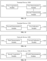
- FIG. 10 is a block diagram of a terminal device 1000 according to some embodiments of this application.
- the terminal device may include a first acquisition module 1010 and a first determination module 1020.
- the first acquisition module 1010 is configured to acquire channel-occupation spatial information.
- the first determination module 1020 is configured to determine, according to the channel-occupation spatial information, channel-sensing spatial information of the terminal device.
- the first acquisition module 1010 is configured to acquire the channel-occupation spatial information from the DCI carrying the UL grant.
- the channel-occupation spatial information indicated in the DCI carrying the UL grant is indicated by at least one of following:
- the channel-occupation spatial information includes: channel-sensing spatial information of the terminal device.
- the terminal device 1000 further includes a first transmission module 1130.
- the first transmission module 1130 is configured to perform a channel sensing according to the channel-sensing spatial information of the terminal device, and when a result of the channel sensing indicates a free channel, using the free channel for uplink transmission.
- the first acquisition module 1010 is configured to acquire the channel-occupation spatial information in a preset manner.
- the preset manner includes at least one of the following:
- the first acquisition module 1010 is configured to acquire the channel-occupation spatial information from the Msg2 in the random access procedure.
- the channel-occupation spatial information indicated by the Msg2 in the random access procedure is indicated by at least one of following:
- the channel-occupation spatial information includes: channel-sensing spatial information of the terminal device.
- the terminal device 1000 may further include a second transmission module 1230.
- the second transmission module 1230 is configured to perform a channel sensing according to the channel-sensing spatial information of the terminal device, and when a result of the channel sensing indicates a free channel, uses the free channel for transmission of Msg 3 in a random access procedure.
- the first acquisition module 1010 is configured to acquire the channel-occupation spatial information in a preset manner.
- the preset manner includes at least one of the following:
- the first acquisition module 1010 is configured to acquire the channel-occupation spatial information from the group common PDCCH.
- the first acquisition module 1010 is configured to acquire the channel-occupation spatial information from a DCI format 2_0 in the group common PDCCH.
- the channel-occupation spatial information indicated in the DCI format 2_0 is indicated by at least one of following:
- the first acquisition module 1010 is configured to acquire the channel-occupation spatial information in a preset manner.
- the preset manner includes: determining the channel-occupation spatial information according to spatial information for receiving the DCI format 2_0.
- the channel-occupation spatial information includes: channel-occupation spatial information of the network device.
- the channel-sensing spatial information of the terminal device includes: LBT directional information of the terminal device.
- FIG. 13 is a block diagram of a terminal device 1300 according to some embodiments of this application.
- the terminal device includes a second determination module 1310 and a first indication module 1320.
- the second determination module 1310 is configured to determine the channel-occupation spatial information.
- the first indication module 1320 is configured to indicate the channel-occupation spatial information.
- the channel-occupation spatial information includes: channel-sensing spatial information of the terminal device or channel-sensing spatial information of a network device.
- the first indication module 1320 is configured to indicate the channel-occupation spatial information through the UCI carried in the CG-UL.
- the channel-occupation spatial information is used for determining channel-sensing spatial information of the network device.
- the channel-sensing spatial information of the network device includes LBT directional information of the network device.
- FIG. 14 is a block diagram of a network device 1400 according to some embodiments of this application.
- the network device includes a third determination module 1410 and a second indication module 1420.
- the third determination module 1410 is configured to determine the channel-occupation spatial information.
- the second indication module 1420 is configured to indicate the channel-occupation spatial information.
- the second indication module 1420 is configured to indicate the channel-occupation spatial information by using the DCI carrying the UL grant.
- the channel-occupation spatial information is indicated by at least one of the following in the DCI carrying the UL grant:
- the second indication module 1420 is configured to indicate the channel-occupation spatial information by using Msg2 in the random access procedure.
- the channel-occupation spatial information is indicated by at least one of the following items in Msg2 in the random access procedure:
- the channel-occupation spatial information includes: channel-sensing spatial information of the terminal device.
- the second indication module 1420 is configured to indicate the channel-occupation spatial information by using a group common PDCCH.
- the second indication module 1420 is configured to indicate the channel-occupation spatial information by using the DCI format 2_0 in the group common PDCCH.
- the channel-occupation spatial information is indicated by using at least one of the following in DCI format 2_0:
- the channel-occupation spatial information includes: channel-sensing spatial information of the network device.
- the channel-occupation spatial information is used for determining the channel-sensing spatial information of the terminal device.
- FIG. 15 is a block diagram of a network device 1500 according to some embodiments of this application.
- the network device includes a second acquisition module 1510 and a fourth determination module 1520.
- the second acquisition module 1510 is configured to acquire channel-occupation spatial information.
- the fourth determination module 1520 is configured to determine the channel-sensing spatial information of the network device according to the channel-occupation spatial information.
- the channel-occupation spatial information includes: channel-sensing spatial information of a terminal device or channel-sensing spatial information of the network device.
- the second acquisition module 1510 is configured to acquire the channel-occupation spatial information from the UCI carried in the CG-UL.
- the channel-sensing spatial information of the network device includes: LBT directional information of the network device.
- FIG. 16 is a block diagram of a communication device 1600 according to some embodiments of this application.
- the communication device 1600 shown in FIG. 16 includes a processor 1610, and the processor 1610 is configured to call and run a computer program from a memory to implement the method in some embodiments of this application.
- the communication device 1600 may further include a memory 1620.
- the processor 1610 is configured to call and run the computer program from the memory 1620 to implement the method in some embodiments of this application.
- the memory 1620 may be a separate device independent of the processor 1610, or may be integrated in the processor 1610.
- the communication device 1600 may further include a transceiver 1630, and the processor 1610 is configured to control the transceiver 1630 to communicate with other devices.
- the transceiver 1630 may send information or data to other devices, or receive information or data sent by the other devices.
- the transceiver 1630 may include a transmitter and a receiver.
- the transceiver 1630 may further include an antenna, and the number of antennas may be one or more.
- the communication device 1600 may be the network device in some embodiments of this application, and the communication device 1600 may implement corresponding processes implemented by the network device in each method according to the embodiments of this application. For brevity, details are not repeated herein.
- the communication device 1600 may be the terminal device in some embodiments of this application, and the communication device 1600 may implement corresponding processes implemented by the terminal device in each method according to the embodiments of this application. For brevity, details are not repeated herein.
- FIG. 17 is a block diagram of a chip 1700 according to some embodiments of this application.
- the chip 1700 shown in FIG. 17 includes a processor 1710, and the processor 1710 is configured to call and run a computer program from a memory to implement the method in some embodiments of this application.
- the chip 1700 may further include a memory 1720.
- the processor 1710 is configured to call and run the computer program from the memory 1720 to implement the method in some embodiments of this application.
- the memory 1720 may be a separate device independent of the processor 1710, or may be integrated in the processor 1710.
- the chip 1700 may further include an input interface 1730.
- the processor 1710 is configured to control the input interface 1730 to communicate with other devices or chips, and specifically, may obtain information or data sent by other devices or chips.
- the chip 1700 may further include an output interface 1740.
- the processor 1710 is configured to control the output interface 1740 to communicate with other devices or chips, and specifically, may output information or data to other devices or chips.
- the chip 1700 may be applied to the network device in some embodiments of this application, and the chip may implement the corresponding processes implemented by the network device in the various methods according to the embodiments of this application. For brevity, details are not repeated herein.
Landscapes
- Engineering & Computer Science (AREA)
- Signal Processing (AREA)
- Computer Networks & Wireless Communication (AREA)
- Quality & Reliability (AREA)
- Computer Security & Cryptography (AREA)
- Mobile Radio Communication Systems (AREA)
- Communication Control (AREA)
Claims (11)
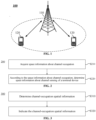
- Procédé de détermination d'informations, appliqué à un dispositif terminal, comprenant :l'acquisition (S210) d'informations directionnelles d'occupation de canal à partir d'une signalisation de commande de liaison descendante, DCI, transportant une attribution de liaison montante, UL ;la détermination (S220), selon les informations directionnelles d'occupation de canal, d'informations directionnelles écouter-avant-de-parler, LBT, du dispositif terminal, les informations directionnelles LBT étant utilisées pour établir une direction de faisceau de transmission ; etla réalisation, par le dispositif terminal, d'une détection de canal selon les informations directionnelles LBT du dispositif terminal, et lorsqu'un résultat de la détection de canal indique un canal libre, l'utilisation du canal libre pour une transmission en liaison montante,dans lequel les informations directionnelles d'occupation de canal indiquées dans la DCI transportant l'attribution UL sont indiquées par au moins l'un des éléments suivants :un indice de bloc de signal de synchronisation/canal de diffusion physique, SS/PBCH ;une identification de ressources d'un signal de référence d'informations d'état de canal à puissance non nulle, NZP-CSI-RS, ;une identification de ressources d'un signal de référence de sondage, SRS ;un état d'une indication de configuration de transmission, TCI ; etun indicateur de ressources SRS,dans lequel la DCI est DCI format 0_1 ou DCI format 2_0.
- Procédé selon la revendication 1, dans lequel l'acquisition (S210) des informations directionnelles d'occupation de canal comprend en outre :l'acquisition des informations directionnelles d'occupation de canal à partir d'un message d'information système ;l'acquisition des informations directionnelles d'occupation de canal à partir d'un message de commande de ressources radio, RRC ;l'acquisition des informations directionnelles d'occupation de canal selon des informations spatiales mesurées par le dispositif terminal ;l'acquisition des informations directionnelles d'occupation de canal selon des informations spatiales reçues par le biais d'un canal de liaison descendante ; et/oul'acquisition des informations directionnelles d'occupation de canal à partir d'informations d'indication de configuration de transmission, TCI, indiquées par un dispositif de réseau.
- Procédé selon la revendication 1 ou 2, comprenant en outre :
l'acquisition, par le dispositif terminal, des informations directionnelles d'occupation de canal selon un état TCI configuré par un dispositif de réseau, l'état TCI étant activé au moyen d'un élément de commande, CE, de commande d'accès au support, MAC. - Procédé selon la revendication 1, dans lequel l'acquisition des informations directionnelles d'occupation de canal comprend :l'acquisition des informations directionnelles d'occupation de canal à partir d'un message Msg2 dans une procédure d'accès aléatoire,dans lequel les informations directionnelles d'occupation de canal indiquées par le Msg2 dans la procédure d'accès aléatoire sont indiquées par au moins l'un des éléments suivants :un indice de bloc SS/PBCH ;une identification de ressources NZP-CSI-RS ;une identification de ressources SRS ; etun état TCI,et le procédé comprend en outre :
l'utilisation du canal libre pour la transmission d'un Msg3 dans une procédure d'accès aléatoire. - Procédé d'indication d'informations, appliqué à un dispositif de réseau, comprenant :la détermination (S410) d'informations directionnelles d'occupation de canal ; etl'indication (S420) des informations directionnelles d'occupation de canal à l'aide d'une signalisation de commande de liaison descendante, DCI, transportant une attribution de liaison montante, UL,dans lequel les informations directionnelles d'occupation de canal sont utilisées par un dispositif terminal pour déterminer des informations directionnelles écouter-avant-de-parler, LBT, du dispositif terminal, et les informations directionnelles LBT sont utilisées pour établir une direction de faisceau de transmission ;dans lequel les informations directionnelles d'occupation de canal sont indiquées par au moins un des éléments suivants dans la DCI transportant l'attribution UL :un indice de bloc de signal de synchronisation/canal de diffusion physique, SS/PBCH ;une identification de ressources d'un signal de référence d'informations d'état de canal à puissance non nulle, NZP-CSI-RS, ;une identification de ressources d'un signal de référence de sondage, SRS ;un état d'indication de configuration de transmission, TCI ; etun indicateur de ressources SRS,dans lequel la DCI est DCI format 0_1 ou DCI format 2_0.
- Procédé selon la revendication 5, dans lequel l'indication (S420) des informations directionnelles d'occupation de canal comprend :l'indication des informations directionnelles d'occupation de canal à l'aide d'un message Msg2 dans une procédure d'accès aléatoire,dans lequel les informations directionnelles d'occupation de canal sont indiquées par au moins un des éléments suivants dans le Msg2 dans la procédure d'accès aléatoire :un indice de bloc SS/PBCH ;une identification de ressources NZP-CSI-RS ;une identification de ressources SRS ; etun état TCI.
- Dispositif terminal, comprenant :un premier module d'acquisition (1010), configuré pour acquérir des informations directionnelles d'occupation de canal à partir d'une signalisation de commande de liaison descendante, DCI, transportant une attribution de liaison montante, UL ;un premier module de détermination (1020), configurée pour déterminer, selon les informations directionnelles d'occupation de canal, des informations directionnelles écouter-avant-de-parler, LBT, du dispositif terminal, dans lequel les informations directionnelles LBT sont utilisées pour établir une direction de faisceau de transmission ; etun premier module de transmission (1030) configuré pour effectuer une détection de canal selon les informations directionnelles LBT du dispositif terminal, et lorsqu'un résultat de la détection de canal indique un canal libre, l'utilisation du canal libre pour une transmission en liaison montante,dans lequel les informations directionnelles d'occupation de canal indiquées dans la DCI transportant l'attribution UL sont indiquées par au moins l'un des éléments suivants :un indice de bloc de signal de synchronisation/canal de diffusion physique, SS/PBCH ;une identification de ressources d'un signal de référence d'informations d'état de canal à puissance non nulle, NZP-CSI-RS, ;une identification de ressources d'un signal de référence de sondage, SRS ;un état d'une indication de configuration de transmission, TCI ; etun indicateur de ressources SRS,dans lequel la DCI est DCI format 0_1 ou DCI format 2_0.
- Dispositif de réseau, comprenant :un troisième module de détermination (1410), configuré pour déterminer des informations directionnelles d'occupation de canal ; etun second module d'indication (1420), configuré pour indiquer les informations directionnelles d'occupation de canal à l'aide d'une signalisation de commande de liaison descendante, DCI, transportant une attribution de liaison montante, UL,dans lequel les informations directionnelles d'occupation de canal sont utilisées par un dispositif terminal pour déterminer des informations directionnelles écouter-avant-de-parler, LBT, du dispositif terminal, et les informations directionnelles LBT sont utilisées pour établir une direction de faisceau de transmission ;dans lequel les informations directionnelles d'occupation de canal sont indiquées par au moins un des éléments suivants dans la DCI transportant l'attribution UL :un indice de bloc de signal de synchronisation/canal de diffusion physique, SS/PBCH ;une identification de ressources d'un signal de référence d'informations d'état de canal à puissance non nulle, NZP-CSI-RS, ;une identification de ressources d'un signal de référence de sondage, SRS ;un état d'indication de configuration de transmission, TCI ; etun indicateur de ressources SRS,dans lequel la DCI est DCI format 0_1 ou DCI format 2_0.
- Dispositif terminal, comprenant un processeur et une mémoire, dans lequel la mémoire est configurée pour stocker un programme informatique qui, lorsqu'il est exécuté sur le processeur, amène le processeur à réaliser le procédé selon l'une quelconque des revendications 1 à 4.
- Dispositif de réseau, comprenant un processeur et une mémoire, dans lequel la mémoire est configurée pour stocker un programme informatique qui, lorsqu'il est exécuté sur le processeur, amène le processeur à réaliser le procédé selon l'une quelconque des revendications 5 à 6.
- Support lisible par ordinateur, sur lequel est stocké un programme informatique qui, lorsqu'il est exécuté sur un processeur, amène le programme informatique à mettre en œuvre le procédé selon l'une quelconque des revendications 1 à 6.
Priority Applications (1)
| Application Number | Priority Date | Filing Date | Title |
|---|---|---|---|
| EP25155780.7A EP4531477A3 (fr) | 2020-01-09 | 2020-01-09 | Procédé de détermination d'informations, procédé d'indication d'informations, dispositif terminal et dispositif de réseau |
Applications Claiming Priority (1)
| Application Number | Priority Date | Filing Date | Title |
|---|---|---|---|
| PCT/CN2020/071122 WO2021138866A1 (fr) | 2020-01-09 | 2020-01-09 | Procédé de détermination d'informations, procédé d'indication d'informations, dispositif terminal et dispositif réseau |
Related Child Applications (2)
| Application Number | Title | Priority Date | Filing Date |
|---|---|---|---|
| EP25155780.7A Division-Into EP4531477A3 (fr) | 2020-01-09 | 2020-01-09 | Procédé de détermination d'informations, procédé d'indication d'informations, dispositif terminal et dispositif de réseau |
| EP25155780.7A Division EP4531477A3 (fr) | 2020-01-09 | 2020-01-09 | Procédé de détermination d'informations, procédé d'indication d'informations, dispositif terminal et dispositif de réseau |
Publications (3)
| Publication Number | Publication Date |
|---|---|
| EP4080962A1 EP4080962A1 (fr) | 2022-10-26 |
| EP4080962A4 EP4080962A4 (fr) | 2022-12-14 |
| EP4080962B1 true EP4080962B1 (fr) | 2025-04-16 |
Family
ID=76787403
Family Applications (2)
| Application Number | Title | Priority Date | Filing Date |
|---|---|---|---|
| EP20912787.7A Active EP4080962B1 (fr) | 2020-01-09 | 2020-01-09 | Procédé de détermination d'informations, procédé d'indication d'informations, dispositif terminal et dispositif réseau |
| EP25155780.7A Pending EP4531477A3 (fr) | 2020-01-09 | 2020-01-09 | Procédé de détermination d'informations, procédé d'indication d'informations, dispositif terminal et dispositif de réseau |
Family Applications After (1)
| Application Number | Title | Priority Date | Filing Date |
|---|---|---|---|
| EP25155780.7A Pending EP4531477A3 (fr) | 2020-01-09 | 2020-01-09 | Procédé de détermination d'informations, procédé d'indication d'informations, dispositif terminal et dispositif de réseau |
Country Status (6)
| Country | Link |
|---|---|
| US (1) | US20220338262A1 (fr) |
| EP (2) | EP4080962B1 (fr) |
| KR (1) | KR20220124215A (fr) |
| CN (2) | CN114642057A (fr) |
| ES (1) | ES3029283T3 (fr) |
| WO (1) | WO2021138866A1 (fr) |
Families Citing this family (4)
| Publication number | Priority date | Publication date | Assignee | Title |
|---|---|---|---|---|
| US11917588B2 (en) * | 2020-03-31 | 2024-02-27 | Qualcomm Incorporated | Configured communications techniques in shared radio frequency spectrum based on channel occupancy time |
| CN115399019B (zh) * | 2020-04-08 | 2025-04-18 | 苹果公司 | 用于无线通信中的信道状态信息反馈的介质和用户装备 |
| WO2022188097A1 (fr) * | 2021-03-11 | 2022-09-15 | Lenovo (Beijing) Limited | Procédé et appareil de surveillance d'informations de commande de liaison descendante |
| CN117336872A (zh) * | 2022-06-22 | 2024-01-02 | 维沃移动通信有限公司 | 共享信道的方法、设备及可读存储介质 |
Citations (1)
| Publication number | Priority date | Publication date | Assignee | Title |
|---|---|---|---|---|
| WO2017083514A1 (fr) * | 2015-11-10 | 2017-05-18 | Idac Holdings, Inc. | Conception et signalisation de canal de commande de liaison descendante pour systèmes formés par faisceau |
Family Cites Families (13)
| Publication number | Priority date | Publication date | Assignee | Title |
|---|---|---|---|---|
| CN105101300A (zh) * | 2014-05-09 | 2015-11-25 | 中兴通讯股份有限公司 | 基于竞争的资源选择方法及装置 |
| CN106851839B (zh) * | 2017-03-14 | 2020-06-12 | 北京佰才邦技术有限公司 | 帧结构确定方法和基站 |
| CN110049559B (zh) * | 2018-01-17 | 2021-11-12 | 维沃移动通信有限公司 | 侦听指示方法、终端及网络设备 |
| US11051353B2 (en) * | 2018-03-19 | 2021-06-29 | Apple Inc. | PUCCH and PUSCH default beam considering beam failure recovery |
| CN110366248B (zh) * | 2018-04-04 | 2024-04-30 | 中兴通讯股份有限公司 | 上行传输、通信方法、装置及基站、终端、存储介质 |
| CN110351881B (zh) * | 2018-04-04 | 2021-11-19 | 展讯通信(上海)有限公司 | 信道接入方法及装置、存储介质、终端、基站 |
| US10856320B2 (en) * | 2018-04-06 | 2020-12-01 | Lenovo (Singapore) Pte. Ltd. | Configuring for bandwidth parts |
| CN110505026B (zh) * | 2018-05-18 | 2022-03-29 | 华为技术有限公司 | 信号侦听的方法、相关设备及系统 |
| US11140711B2 (en) * | 2018-08-08 | 2021-10-05 | Acer Incorporated | Method for downlink reception and user equipment using the same |
| CN110972288B (zh) * | 2018-09-28 | 2024-09-20 | 华为技术有限公司 | 传输信号的方法和通信装置 |
| CN111343718B (zh) * | 2018-12-18 | 2022-09-09 | 北京紫光展锐通信技术有限公司 | 占有时隙的确定方法及装置、存储介质、用户终端 |
| CN110040550B (zh) * | 2019-04-22 | 2020-06-12 | 四川华净净化设备科技有限公司 | 用于彩钢夹芯板制造机的限位导向装置 |
| CN117098233A (zh) * | 2019-09-16 | 2023-11-21 | 中兴通讯股份有限公司 | 数据传输方法、装置和系统 |
-
2020
- 2020-01-09 WO PCT/CN2020/071122 patent/WO2021138866A1/fr not_active Ceased
- 2020-01-09 CN CN202080076210.2A patent/CN114642057A/zh active Pending
- 2020-01-09 ES ES20912787T patent/ES3029283T3/es active Active
- 2020-01-09 EP EP20912787.7A patent/EP4080962B1/fr active Active
- 2020-01-09 EP EP25155780.7A patent/EP4531477A3/fr active Pending
- 2020-01-09 KR KR1020227026824A patent/KR20220124215A/ko not_active Ceased
- 2020-01-09 CN CN202210551945.7A patent/CN114845417B/zh active Active
-
2022
- 2022-07-06 US US17/858,654 patent/US20220338262A1/en active Pending
Patent Citations (1)
| Publication number | Priority date | Publication date | Assignee | Title |
|---|---|---|---|---|
| WO2017083514A1 (fr) * | 2015-11-10 | 2017-05-18 | Idac Holdings, Inc. | Conception et signalisation de canal de commande de liaison descendante pour systèmes formés par faisceau |
Also Published As
| Publication number | Publication date |
|---|---|
| US20220338262A1 (en) | 2022-10-20 |
| CN114845417B (zh) | 2024-11-05 |
| EP4080962A1 (fr) | 2022-10-26 |
| EP4531477A2 (fr) | 2025-04-02 |
| KR20220124215A (ko) | 2022-09-13 |
| CN114845417A (zh) | 2022-08-02 |
| EP4080962A4 (fr) | 2022-12-14 |
| EP4531477A3 (fr) | 2025-04-09 |
| ES3029283T3 (en) | 2025-06-23 |
| CN114642057A (zh) | 2022-06-17 |
| WO2021138866A1 (fr) | 2021-07-15 |
Similar Documents
| Publication | Publication Date | Title |
|---|---|---|
| US12507158B2 (en) | Method for indicating antenna switching capability, terminal device and communication device | |
| US12519535B2 (en) | Antenna switching method, terminal device and communication device | |
| JP7040617B2 (ja) | シグナリング指示及び受信方法、装置及び通信システム | |
| US20220338262A1 (en) | Information determination method, information indication method, terminal device, and network device | |
| EP4075905B1 (fr) | Procédé de communication sans fil, équipement terminal et dispositif de réseau | |
| US11546044B2 (en) | Wireless communication method, terminal device and network device | |
| CN113169848A (zh) | 无线通信方法、终端设备和网络设备 | |
| US12231916B2 (en) | Wireless communication method and device | |
| CN112423370A (zh) | 信号传输的方法、网络设备和终端设备 | |
| CN115699894A (zh) | 无线通信方法、终端设备和网络设备 | |
| EP4109938B1 (fr) | Procédé d'envoi de capacité de liaison latérale et dispositif terminal | |
| CN113574944A (zh) | 无线通信方法、网络设备和终端设备 | |
| US12149457B2 (en) | Downlink transmission method and terminal device | |
| US11792831B2 (en) | Method and device for signal transmission | |
| US20220337306A1 (en) | Method for beam selection, terminal device, and network device | |
| US20220312353A1 (en) | Signal detection method, signal transmission method, terminal device, and network device |
Legal Events
| Date | Code | Title | Description |
|---|---|---|---|
| STAA | Information on the status of an ep patent application or granted ep patent |
Free format text: STATUS: THE INTERNATIONAL PUBLICATION HAS BEEN MADE |
|
| PUAI | Public reference made under article 153(3) epc to a published international application that has entered the european phase |
Free format text: ORIGINAL CODE: 0009012 |
|
| STAA | Information on the status of an ep patent application or granted ep patent |
Free format text: STATUS: REQUEST FOR EXAMINATION WAS MADE |
|
| 17P | Request for examination filed |
Effective date: 20220718 |
|
| AK | Designated contracting states |
Kind code of ref document: A1 Designated state(s): AL AT BE BG CH CY CZ DE DK EE ES FI FR GB GR HR HU IE IS IT LI LT LU LV MC MK MT NL NO PL PT RO RS SE SI SK SM TR |
|
| A4 | Supplementary search report drawn up and despatched |
Effective date: 20221115 |
|
| RIC1 | Information provided on ipc code assigned before grant |
Ipc: H04W 72/04 20090101AFI20221109BHEP |
|
| DAV | Request for validation of the european patent (deleted) | ||
| DAX | Request for extension of the european patent (deleted) | ||
| STAA | Information on the status of an ep patent application or granted ep patent |
Free format text: STATUS: EXAMINATION IS IN PROGRESS |
|
| 17Q | First examination report despatched |
Effective date: 20230825 |
|
| GRAP | Despatch of communication of intention to grant a patent |
Free format text: ORIGINAL CODE: EPIDOSNIGR1 |
|
| STAA | Information on the status of an ep patent application or granted ep patent |
Free format text: STATUS: GRANT OF PATENT IS INTENDED |
|
| INTG | Intention to grant announced |
Effective date: 20241218 |
|
| GRAS | Grant fee paid |
Free format text: ORIGINAL CODE: EPIDOSNIGR3 |
|
| GRAA | (expected) grant |
Free format text: ORIGINAL CODE: 0009210 |
|
| STAA | Information on the status of an ep patent application or granted ep patent |
Free format text: STATUS: THE PATENT HAS BEEN GRANTED |
|
| AK | Designated contracting states |
Kind code of ref document: B1 Designated state(s): AL AT BE BG CH CY CZ DE DK EE ES FI FR GB GR HR HU IE IS IT LI LT LU LV MC MK MT NL NO PL PT RO RS SE SI SK SM TR |
|
| REG | Reference to a national code |
Ref country code: GB Ref legal event code: FG4D |
|
| REG | Reference to a national code |
Ref country code: CH Ref legal event code: EP |
|
| REG | Reference to a national code |
Ref country code: IE Ref legal event code: FG4D |
|
| REG | Reference to a national code |
Ref country code: DE Ref legal event code: R096 Ref document number: 602020049742 Country of ref document: DE |
|
| REG | Reference to a national code |
Ref country code: NL Ref legal event code: FP |
|
| REG | Reference to a national code |
Ref country code: ES Ref legal event code: FG2A Ref document number: 3029283 Country of ref document: ES Kind code of ref document: T3 Effective date: 20250623 |
|
| REG | Reference to a national code |
Ref country code: AT Ref legal event code: MK05 Ref document number: 1786733 Country of ref document: AT Kind code of ref document: T Effective date: 20250416 |
|
| P01 | Opt-out of the competence of the unified patent court (upc) registered |
Free format text: CASE NUMBER: UPC_APP_5275_4080962/2025 Effective date: 20250829 |
|
| PG25 | Lapsed in a contracting state [announced via postgrant information from national office to epo] |
Ref country code: FI Free format text: LAPSE BECAUSE OF FAILURE TO SUBMIT A TRANSLATION OF THE DESCRIPTION OR TO PAY THE FEE WITHIN THE PRESCRIBED TIME-LIMIT Effective date: 20250416 Ref country code: PT Free format text: LAPSE BECAUSE OF FAILURE TO SUBMIT A TRANSLATION OF THE DESCRIPTION OR TO PAY THE FEE WITHIN THE PRESCRIBED TIME-LIMIT Effective date: 20250818 |
|
| REG | Reference to a national code |
Ref country code: LT Ref legal event code: MG9D |
|
| PG25 | Lapsed in a contracting state [announced via postgrant information from national office to epo] |
Ref country code: NO Free format text: LAPSE BECAUSE OF FAILURE TO SUBMIT A TRANSLATION OF THE DESCRIPTION OR TO PAY THE FEE WITHIN THE PRESCRIBED TIME-LIMIT Effective date: 20250716 Ref country code: GR Free format text: LAPSE BECAUSE OF FAILURE TO SUBMIT A TRANSLATION OF THE DESCRIPTION OR TO PAY THE FEE WITHIN THE PRESCRIBED TIME-LIMIT Effective date: 20250717 |
|
| PG25 | Lapsed in a contracting state [announced via postgrant information from national office to epo] |
Ref country code: PL Free format text: LAPSE BECAUSE OF FAILURE TO SUBMIT A TRANSLATION OF THE DESCRIPTION OR TO PAY THE FEE WITHIN THE PRESCRIBED TIME-LIMIT Effective date: 20250416 |
|
| PG25 | Lapsed in a contracting state [announced via postgrant information from national office to epo] |
Ref country code: BG Free format text: LAPSE BECAUSE OF FAILURE TO SUBMIT A TRANSLATION OF THE DESCRIPTION OR TO PAY THE FEE WITHIN THE PRESCRIBED TIME-LIMIT Effective date: 20250416 |
|
| PG25 | Lapsed in a contracting state [announced via postgrant information from national office to epo] |
Ref country code: HR Free format text: LAPSE BECAUSE OF FAILURE TO SUBMIT A TRANSLATION OF THE DESCRIPTION OR TO PAY THE FEE WITHIN THE PRESCRIBED TIME-LIMIT Effective date: 20250416 |
|
| PG25 | Lapsed in a contracting state [announced via postgrant information from national office to epo] |
Ref country code: AT Free format text: LAPSE BECAUSE OF FAILURE TO SUBMIT A TRANSLATION OF THE DESCRIPTION OR TO PAY THE FEE WITHIN THE PRESCRIBED TIME-LIMIT Effective date: 20250416 |
|
| PG25 | Lapsed in a contracting state [announced via postgrant information from national office to epo] |
Ref country code: RS Free format text: LAPSE BECAUSE OF FAILURE TO SUBMIT A TRANSLATION OF THE DESCRIPTION OR TO PAY THE FEE WITHIN THE PRESCRIBED TIME-LIMIT Effective date: 20250716 |
|
| PG25 | Lapsed in a contracting state [announced via postgrant information from national office to epo] |
Ref country code: IS Free format text: LAPSE BECAUSE OF FAILURE TO SUBMIT A TRANSLATION OF THE DESCRIPTION OR TO PAY THE FEE WITHIN THE PRESCRIBED TIME-LIMIT Effective date: 20250816 |
|
| PG25 | Lapsed in a contracting state [announced via postgrant information from national office to epo] |
Ref country code: LV Free format text: LAPSE BECAUSE OF FAILURE TO SUBMIT A TRANSLATION OF THE DESCRIPTION OR TO PAY THE FEE WITHIN THE PRESCRIBED TIME-LIMIT Effective date: 20250416 |
|
| PG25 | Lapsed in a contracting state [announced via postgrant information from national office to epo] |
Ref country code: DK Free format text: LAPSE BECAUSE OF FAILURE TO SUBMIT A TRANSLATION OF THE DESCRIPTION OR TO PAY THE FEE WITHIN THE PRESCRIBED TIME-LIMIT Effective date: 20250416 Ref country code: SM Free format text: LAPSE BECAUSE OF FAILURE TO SUBMIT A TRANSLATION OF THE DESCRIPTION OR TO PAY THE FEE WITHIN THE PRESCRIBED TIME-LIMIT Effective date: 20250416 |
|
| REG | Reference to a national code |
Ref country code: DE Ref legal event code: R097 Ref document number: 602020049742 Country of ref document: DE |
|
| PG25 | Lapsed in a contracting state [announced via postgrant information from national office to epo] |
Ref country code: CZ Free format text: LAPSE BECAUSE OF FAILURE TO SUBMIT A TRANSLATION OF THE DESCRIPTION OR TO PAY THE FEE WITHIN THE PRESCRIBED TIME-LIMIT Effective date: 20250416 |
|
| PG25 | Lapsed in a contracting state [announced via postgrant information from national office to epo] |
Ref country code: EE Free format text: LAPSE BECAUSE OF FAILURE TO SUBMIT A TRANSLATION OF THE DESCRIPTION OR TO PAY THE FEE WITHIN THE PRESCRIBED TIME-LIMIT Effective date: 20250416 |
|
| PG25 | Lapsed in a contracting state [announced via postgrant information from national office to epo] |
Ref country code: SK Free format text: LAPSE BECAUSE OF FAILURE TO SUBMIT A TRANSLATION OF THE DESCRIPTION OR TO PAY THE FEE WITHIN THE PRESCRIBED TIME-LIMIT Effective date: 20250416 |
|
| PGFP | Annual fee paid to national office [announced via postgrant information from national office to epo] |
Ref country code: NL Payment date: 20260128 Year of fee payment: 7 |
|
| PLBE | No opposition filed within time limit |
Free format text: ORIGINAL CODE: 0009261 |
|
| STAA | Information on the status of an ep patent application or granted ep patent |
Free format text: STATUS: NO OPPOSITION FILED WITHIN TIME LIMIT |
|
| REG | Reference to a national code |
Ref country code: CH Ref legal event code: L10 Free format text: ST27 STATUS EVENT CODE: U-0-0-L10-L00 (AS PROVIDED BY THE NATIONAL OFFICE) Effective date: 20260225 |
|
| 26N | No opposition filed |
Effective date: 20260119 |
|
| PGFP | Annual fee paid to national office [announced via postgrant information from national office to epo] |
Ref country code: GB Payment date: 20260123 Year of fee payment: 7 |
|
| PGFP | Annual fee paid to national office [announced via postgrant information from national office to epo] |
Ref country code: ES Payment date: 20260203 Year of fee payment: 7 |
|
| PGFP | Annual fee paid to national office [announced via postgrant information from national office to epo] |
Ref country code: DE Payment date: 20260126 Year of fee payment: 7 |
|
| PGFP | Annual fee paid to national office [announced via postgrant information from national office to epo] |
Ref country code: IT Payment date: 20260126 Year of fee payment: 7 |
|
| PGFP | Annual fee paid to national office [announced via postgrant information from national office to epo] |
Ref country code: FR Payment date: 20260129 Year of fee payment: 7 |