EP4081077B1 - Beschichtetes metallisches kochgestell, das durch induktion erhitzt werden kann - Google Patents
Beschichtetes metallisches kochgestell, das durch induktion erhitzt werden kann Download PDFInfo
- Publication number
- EP4081077B1 EP4081077B1 EP20838554.2A EP20838554A EP4081077B1 EP 4081077 B1 EP4081077 B1 EP 4081077B1 EP 20838554 A EP20838554 A EP 20838554A EP 4081077 B1 EP4081077 B1 EP 4081077B1
- Authority
- EP
- European Patent Office
- Prior art keywords
- coated metal
- coating
- compatible
- face
- induction heating
- Prior art date
- Legal status (The legal status is an assumption and is not a legal conclusion. Google has not performed a legal analysis and makes no representation as to the accuracy of the status listed.)
- Active
Links
Images


Classifications
-
- A—HUMAN NECESSITIES
- A47—FURNITURE; DOMESTIC ARTICLES OR APPLIANCES; COFFEE MILLS; SPICE MILLS; SUCTION CLEANERS IN GENERAL
- A47J—KITCHEN EQUIPMENT; COFFEE MILLS; SPICE MILLS; APPARATUS FOR MAKING BEVERAGES
- A47J36/00—Parts, details or accessories of cooking-vessels
- A47J36/02—Selection of specific materials, e.g. heavy bottoms with copper inlay or with insulating inlay
- A47J36/025—Vessels with non-stick features, e.g. coatings
-
- A—HUMAN NECESSITIES
- A47—FURNITURE; DOMESTIC ARTICLES OR APPLIANCES; COFFEE MILLS; SPICE MILLS; SUCTION CLEANERS IN GENERAL
- A47J—KITCHEN EQUIPMENT; COFFEE MILLS; SPICE MILLS; APPARATUS FOR MAKING BEVERAGES
- A47J27/00—Cooking-vessels
- A47J27/002—Construction of cooking-vessels; Methods or processes of manufacturing specially adapted for cooking-vessels
-
- A—HUMAN NECESSITIES
- A47—FURNITURE; DOMESTIC ARTICLES OR APPLIANCES; COFFEE MILLS; SPICE MILLS; SUCTION CLEANERS IN GENERAL
- A47J—KITCHEN EQUIPMENT; COFFEE MILLS; SPICE MILLS; APPARATUS FOR MAKING BEVERAGES
- A47J36/00—Parts, details or accessories of cooking-vessels
- A47J36/02—Selection of specific materials, e.g. heavy bottoms with copper inlay or with insulating inlay
-
- B—PERFORMING OPERATIONS; TRANSPORTING
- B21—MECHANICAL METAL-WORKING WITHOUT ESSENTIALLY REMOVING MATERIAL; PUNCHING METAL
- B21D—WORKING OR PROCESSING OF SHEET METAL OR METAL TUBES, RODS OR PROFILES WITHOUT ESSENTIALLY REMOVING MATERIAL; PUNCHING METAL
- B21D51/00—Making hollow objects
- B21D51/16—Making hollow objects characterised by the use of the objects
- B21D51/18—Making hollow objects characterised by the use of the objects vessels, e.g. tubs, vats, tanks, sinks, or the like
- B21D51/22—Making hollow objects characterised by the use of the objects vessels, e.g. tubs, vats, tanks, sinks, or the like pots, e.g. for cooking
-
- B—PERFORMING OPERATIONS; TRANSPORTING
- B32—LAYERED PRODUCTS
- B32B—LAYERED PRODUCTS, i.e. PRODUCTS BUILT-UP OF STRATA OF FLAT OR NON-FLAT, e.g. CELLULAR OR HONEYCOMB, FORM
- B32B15/00—Layered products comprising a layer of metal
- B32B15/01—Layered products comprising a layer of metal all layers being exclusively metallic
- B32B15/012—Layered products comprising a layer of metal all layers being exclusively metallic one layer being formed of an iron alloy or steel, another layer being formed of aluminium or an aluminium alloy
-
- C—CHEMISTRY; METALLURGY
- C23—COATING METALLIC MATERIAL; COATING MATERIAL WITH METALLIC MATERIAL; CHEMICAL SURFACE TREATMENT; DIFFUSION TREATMENT OF METALLIC MATERIAL; COATING BY VACUUM EVAPORATION, BY SPUTTERING, BY ION IMPLANTATION OR BY CHEMICAL VAPOUR DEPOSITION, IN GENERAL; INHIBITING CORROSION OF METALLIC MATERIAL OR INCRUSTATION IN GENERAL
- C23C—COATING METALLIC MATERIAL; COATING MATERIAL WITH METALLIC MATERIAL; SURFACE TREATMENT OF METALLIC MATERIAL BY DIFFUSION INTO THE SURFACE, BY CHEMICAL CONVERSION OR SUBSTITUTION; COATING BY VACUUM EVAPORATION, BY SPUTTERING, BY ION IMPLANTATION OR BY CHEMICAL VAPOUR DEPOSITION, IN GENERAL
- C23C2/00—Hot-dipping or immersion processes for applying the coating material in the molten state without affecting the shape; Apparatus therefor
- C23C2/04—Hot-dipping or immersion processes for applying the coating material in the molten state without affecting the shape; Apparatus therefor characterised by the coating material
- C23C2/12—Aluminium or alloys based thereon
Definitions
- the present invention relates to the technical field of metal cooking supports compatible with induction heating, for cooking or reheating food.
- metal cooking supports can be used with an induction heating device such as an induction hob placed or integrated into a work surface, or an induction heating hearth integrated into an electric cooking appliance.
- the present invention relates more particularly to coated metal cooking supports compatible with induction heating.
- the present invention relates in particular, but not exclusively, to coated metal cooking supports forming a cooking container.
- the present invention also relates to culinary articles comprising a coated metal cooking support associated with at least one gripping member. If desired, the gripping member(s) can be removable or dismantled in relation to the coated metal cooking support.
- the present invention also relates to electrical cooking appliances comprising a coated metal cooking support associated with an induction heating device.
- a disadvantage of this type of embodiment lies in the fact that such a coated metal cooking support has a relatively high cost price, due in particular to the presence of a striking operation to obtain a metallurgical assembly of the different plates.
- a first aspect of the present invention relates to a coated metal cooking medium compatible with induction heating according to claim 1.
- the low carbon steel used for the ferromagnetic substrate is sensitive to the magnetic field and can be heated by induction.
- Aluminum is, on the contrary, a disruptive material for the magnetic field used for induction heating.
- an intermetallic reaction layer is formed at the interface between the steel and the aluminum.
- the intermetallic compounds of the intermediate layer do not have the disruptive nature of aluminum for the magnetic field used for induction heating.
- the thickness of the external layer comprising an aluminum-based matrix appears to be the main relevant parameter to obtain compatibility with induction hobs.
- the use of such a coated metal body makes it possible to obtain a coated metal cooking support compatible with induction heating which is more economical to produce than a coated metal cooking support comprising an aluminum body associated with a ferromagnetic steel element.
- the use of such a coated metal body makes it possible to obtain a coated metal cooking support compatible with induction heating which is lighter than a coated metal cooking support made from cast steel.
- the outer layer may include Al-Fe-Si needles in an aluminum-silicon matrix.
- An aluminization bath comprising aluminum and silicon makes it easier to produce the outer layer during the aluminization of the steel sheet. Silicon does not have the disruptive nature of aluminum for the magnetic field used for induction heating.
- the ferromagnetic substrate made of low carbon steel may have a thickness of between 0.7 and 3 mm, and preferably a thickness of between 1 and 2 mm.
- the low-carbon steel ferromagnetic substrate can be made of a steel grade containing at most 0.3% by mass of carbon, and preferably between 0.1 and 0.2% by mass of carbon.
- the protective coating can be made directly on the heating face of the metal body.
- the protective coating may comprise one or more layers.
- the non-stick coating can be made directly on the cooking side of the metal body.
- the non-stick coating may have one or more layers. If desired, an intermediate coating can be arranged between the non-stick coating and the metal body, to obtain a hard base.
- the protective coating may in particular be a PTFE type coating, or an enamel type coating, or a lacquer type coating, or a ceramic type coating, or a sol-gel type coating.
- the protective coating can be a PTFE type coating, or a lacquer type coating, or a ceramic type coating, or a sol-gel type coating, the metal body comprising a deposit based on aluminum presenting at least on the bottom of the face of heats a thickness less than 30 ⁇ m, and preferably a thickness less than 20 ⁇ m.
- the protective coating can be an enamel type coating, the metal body comprising an aluminum-based deposit having at least on the bottom of the heating face a thickness less than 40 ⁇ m, and preferably a thickness less than 30 ⁇ m.
- the non-stick coating may be a PTFE type coating, or a ceramic type coating, or a sol-gel type coating.
- the coated metal cooking rack may have a side wall rising around the bottom of the heating face to form a cooking vessel.
- the coated metal cooking support may in particular have a pinched edge or a rolled edge or an open rolled edge. These arrangements make it possible to avoid leaving the edge of the metal body visible.
- a second aspect of the present invention relates to a culinary article according to claim 12.
- a third aspect of the present invention relates to an electric cooking appliance according to claim 13.
- a fourth aspect of the present invention relates to a method of obtaining a coated metal cooking support compatible with induction heating according to claim 14.
- the process may include a step of treating a peripheral part of the shape to obtain a pinched edge or a rolled edge or an open rolled edge.
- the protective coating may in particular be a PTFE type coating, or an enamel type coating, or a lacquer type coating, or a ceramic type coating, or a sol-gel type coating.
- the non-stick coating may in particular be a PTFE type coating, or a ceramic type coating, or a sol-gel type coating.
- a fifth aspect of the present invention relates to a method of obtaining a coated metal cooking support compatible with induction heating according to claim 18.
- the process may include a step of treating a peripheral part of the coated shape to obtain a pinched edge or a rolled edge or a rolled edge open.
- the protective coating may in particular be a PTFE type coating, or a lacquer type coating.
- the non-stick coating may be a PTFE type coating.
- the shape may be a disk.
- Other forms are, however, possible.
- FIG 1 illustrates an exemplary embodiment of a metal body 110 used to produce a coated metal cooking support 100 compatible with induction heating, shown in the Figure 5 .
- the metal body 110 is made of two-sided aluminized low-carbon ferromagnetic steel sheet 101.
- the two-sided aluminization of a low-carbon ferromagnetic steel sheet is obtained by immersion in an aluminization bath based on aluminum, to make a deposit 115 based on aluminum.
- the aluminum-based bath may contain silicon, in particular between 8 and 13% by mass of silicon, to facilitate deposition on the steel.
- An AS type aluminum-silicon alloy can in particular be used, for example an AS alloy comprising between 8 and 13% by mass of silicon.
- an aluminization bath having lower proportions of silicon, or an aluminization bath devoid of silicon can be considered.
- the quantity of material deposited on the low carbon ferromagnetic steel sheet can be evaluated by weighing.
- the additional mass thus obtained makes it possible to define a thickness for the aluminum-based deposit 115 on the steel sheet.
- Such an aluminum-based deposit 115 can reach several tens of ⁇ m.
- the two-sided aluminized low-carbon ferromagnetic steel sheet 101 used to produce the coated metal cooking support 100 compatible with induction heating comprises a substrate ferromagnetic in low carbon steel 111 having on each of its two faces an external layer 112 based on aluminum.
- the ferromagnetic substrate made of low carbon steel 111 may have a thickness of between 0.7 and 3 mm, in particular a thickness of between 1 and 2 mm.
- the material of the ferromagnetic substrate in low carbon steel 111 is chosen to be compatible with induction heating.
- the low-carbon steel ferromagnetic substrate 111 can be made in a steel grade containing at most 0.3% by mass of carbon, and preferably between 0.1 and 0.2% by mass of carbon.
- the ferromagnetic substrate in low carbon steel 111 can in particular be made in a grade DX51 to DX56 comprising between 0.12% and 0.18% by mass of carbon and up to 0.5% by mass of silicon.
- an intermediate layer 113 is arranged between the ferromagnetic low-carbon steel substrate 111 and the outer layer 112.
- the intermediate layer 113 is an intermetallic reaction layer comprising iron/aluminum intermetallic compounds, in particular FeAl 3 and Fe 2 Al 5 .
- FeAl 3 and Fe 2 Al 5 iron/aluminum intermetallic compounds
- this intermediate layer 113 is usually between 3 and 5 ⁇ m. However, heat treatments beyond 500°C can contribute to increasing the thickness of this intermediate layer 113 to the detriment of the thickness of the outer layer 112, this intermediate layer 113 can then be subdivided into several sub-layers having different aluminum/iron ratios, these ratios increasing from the low carbon steel ferromagnetic substrate 111 towards the outer layer 112.
- the outer layer 112 based on aluminum may contain silicon, when the aluminization bath contains silicon, in particular between 8 and 13% by mass of silicon.
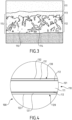
- the outer layer 112 can then include needles of Al-Fe-Si 114 in an aluminum-silicon matrix 116, as visible in the exemplary embodiment illustrated in the Figure 4 .
- the metal body 110 comprises a heating face 120 and a cooking face 130.
- the heating face 120 has a bottom 122 configured to rest on an induction heating device, in particular on an induction hob or on a heating hearth by induction.
- the heating face 120 carries a protective covering 121; the cooking face 130 carries a non-stick coating 131 forming a cooking surface 132.
- the coated metal cooking support 100 compatible with induction heating according to the invention shown on the Figure 4 comprises the metal body 110, the protective coating 121, and the non-stick coating 131.
- the metal body 110 carries the protective coating 121 and the non-stick coating 131.
- the heating face 120 and the cooking face 130 are formed by the double-sided aluminized low-carbon ferromagnetic steel sheet 101.
- the protective coating 121 can be produced directly on the heating face 120 of the metal body 110, in particular on the external layer 112 on the bottom side 122. If necessary, surface preparation can be carried out on the heating face 120 before the production of the protective coating 121.
- the protective coating 121 may in particular be a PTFE type coating, or an enamel type coating, or a lacquer type coating, or a ceramic type coating, or a floor type coating. freeze.
- the non-stick coating 131 can be produced directly on the cooking face 130 of the metal body 110, in particular on the outer layer 112 opposite the bottom 122. If necessary, surface preparation can be carried out on the cooking face 130 before production. of the protective coating 121.
- the non-stick coating 131 may in particular be a PTFE type coating, or a ceramic type coating, or a sol-gel type coating.
- the coated metal cooking support 100 may include a side wall 123 rising around the bottom 122 of the face heating element 120 to form a cooking container 124.
- the coated metal cooking support 100 does not necessarily form a cooking container 124.
- the coated metal cooking support 100 can in particular form a cooking plate.
- the limit value of the thickness of the aluminum-based deposit 115 on the bottom 122 of the heating face 120 to obtain coupling on an induction plate is of the order of 30 ⁇ m when the protective coating 121 is a PTFE type coating, or a lacquer type coating, or a ceramic type coating, or a sol-gel type coating, but the limiting value of the thickness of the deposit 115 based of aluminum on the bottom 122 of the heating face 120 to obtain coupling on an induction hob is of the order of 40 ⁇ m when the protective coating 121 is an enamel type coating.
- the thickness of the intermediate layer 113 is usually of the order of 3 to 5 ⁇ m, but can be greater in particular in the case of heat treatment favoring the growth of the thickness of the intermediate layer 113, where appropriate in the form of several sub-layers, and/or reducing the thickness of the outer layer 112.
- the thickness of the outer layer 112 on the bottom 122 of the heating face 120 is determining for the compatibility of the coated metal cooking support 100 with induction heating. A thickness of less than 27 ⁇ m for the outer layer 112 on the bottom 122 of the heating face 120 is considered as a limiting value for obtaining coupling on an induction plate.
- a thickness less than 26 ⁇ m gives a better result than a thickness less than 27 ⁇ m
- a thickness less than 25 ⁇ m gives a better result than a lesser thickness at 26 ⁇ m
- a thickness less than 24 ⁇ m gives a better result than a thickness less than 25 ⁇ m
- a thickness less than 23 ⁇ m gives a better result than a thickness less than 24 ⁇ m
- a thickness less than 22 ⁇ m gives a better result than a thickness less than 23 ⁇ m
- a thickness less than 21 ⁇ m gives a better result than a thickness less than 22 ⁇ m
- a thickness less than 20 ⁇ m gives a better result than a thickness less than 21 ⁇ m
- a thickness less than 19 ⁇ m gives a better result than a thickness less than 20 ⁇ m
- a thickness less than 18 ⁇ m gives a better result than a thickness less than 19 ⁇ m
- a thickness less than 17 ⁇ m gives a better
- a thickness of less than 20 ⁇ m for the outer layer 112 on the bottom 122 of the heating face 120 allows a fairly satisfactory coupling with the plates to be induction.
- a thickness of less than 18 ⁇ m for the outer layer 112 on the bottom 122 of the heating face 120 allows a very satisfactory coupling with induction hobs.
- the efficiencies power absorbed by the coated metal cooking support 100 / power emitted by the induction hob) can approach 100%.
- the heating speed is very fast.
- the coated metal cooking support 100 compatible with induction heating has an exposed edge 128.
- the slice 128 is generally devoid of external layer 112 due to the cutting of the metal body 110 to produce a shape adapted to the production of the coated metal cooking support 100.
- the slice 128 can be covered at least partially by the protective coating 121 and/or by the non-stick coating 131.
- the exposed edge 128 is covered by the protective coating 121 and/or by the non-stick coating 131.
- the coated metal cooking support 100 compatible with induction heating may have a pinched edge 125.
- the coated metal cooking support 100 compatible with induction heating may have a rolled edge 126.
- the coated metal cooking support 100 compatible with induction heating may have an open rolled edge 127. Thus the edge 128 does not appear on the upper face of the coated metal cooking support 100.
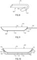
- FIG. 9 illustrates a culinary article 140 comprising the coated metal cooking support 100 and a gripping member 150 mounted on the coated metal cooking support 100.
- the coated metal cooking support 100 forms the cooking container 124 illustrated in the Figure 5 .
- the gripping member 150 is fixed to the cooking container 124 by at least one rivet 151.
- the rivet 151 is mounted in a hole made in the side wall 123. If desired several rivets 151 can be used to fix the gripping member 150 on the cooking container 124. Preferably between two and four rivets 151 are used to fix the gripping member 150 on the cooking container 124.
- the gripping member 150 could be fixed on the side wall 123 by welding or by screwing onto a stud welded to the side wall 123.
- another gripping member can be fixed on the side wall 123 of the cooking container 124 at by means of at least one other rivet, by welding or by screwing onto a stud welded to the side wall 123
- FIG. 10 illustrates an electric cooking appliance 160 comprising the coated metal cooking support 100 associated with an induction heating hearth 170.
- the coated metal cooking support 100 forms the cooking container 124 illustrated in the Figure 5 .
- the cooking container 124 is arranged in a heating base 175 comprising the induction heating hearth 170.
- the bottom 122 rests on the induction heating hearth 170.
- the cooking container 124 can include at least one gripping member 155 .
- the cooking container 124 comprises two opposite gripping members 155.
- the or each gripping member 155 is fixed to the cooking container 124 by at least one rivet 156.
- the rivet 156 is mounted in a hole made in the side wall 123.
- rivets 156 can be used to fix the or each gripping member 155 on the cooking container 124.
- the or at least one of the gripping members 155 could be fixed to the side wall 123 by welding or by screwing onto a stud welded to the side wall 123.
- coated metal cooking support 100 compatible with induction heating according to the invention can be obtained by different processes.
- the shape may in particular be a disk. If desired after stamping the shape and before producing the protective coating 121 and the non-stick coating 131, the first process may include a step of treating a peripheral part of the shape to obtain a pinched edge 125 or a rolled edge 126 or an open rolled edge 127.
- the protective coating 121 and the non-stick coating 131 are produced after the shaping operation.
- the range of coatings that can be used is wide.
- the protective coating 121 may in particular be a PTFE type coating, or an enamel type coating, or a lacquer type coating, or a ceramic type coating, or a sol-gel type coating.
- the non-stick coating 131 may in particular be a PTFE type coating, or a ceramic type coating, or a sol-gel type coating.
- the shape may in particular be a disk.
- the second process may include a step of treating a peripheral part of the coated shape to obtain a pinched edge 125 or a rolled edge 126 or an open rolled edge 127.
- the protective coating 121 and the non-stick coating 131 are produced before the shaping operation.
- the range of coatings that can be used is more restricted.
- the protective coating 121 and the non-stick coating 131 must allow shaping by stamping the shape.
- the protective coating 121 may in particular be a PTFE type coating, or a lacquer type coating.
- the non-stick coating 131 may in particular be a PTFE type coating.
- the use of a two-sided aluminized low-carbon ferromagnetic steel sheet 101 to produce the coated metal cooking support 100 makes it possible to use a cheaper raw material than the usual aluminum and stainless steel products.
- the use of a two-sided aluminized low-carbon ferromagnetic steel sheet 101 to produce the coated metal cooking support 100 also makes it possible to use conventional manufacturing processes, which limits the necessary investments.
- the coated metal cooking rack 100 is light and very mechanically resistant. Deformations during use are much less than with cooking supports combining aluminum and stainless steel, due to the absence of a bimetallic effect.
- the efficiency (power absorbed / power emitted by the induction heating device) is very high, particularly if the thickness of the aluminum-based deposit 115 is less than 20 ⁇ m.
- the heating speed is high: 15 seconds for a pan with a diameter of 28 cm compared to around 1min30 for a standard aluminum pan of the same diameter with a stainless steel insert for compatibility with induction heating.
Landscapes
- Engineering & Computer Science (AREA)
- Food Science & Technology (AREA)
- Manufacturing & Machinery (AREA)
- Mechanical Engineering (AREA)
- Cookers (AREA)
Claims (22)
- Beschichtetes Metallkochgefäß (100), das mit einer Induktionsheizung kompatibel ist, einen Metallkörper (110) umfassend, der eine Heizseite (120) und eine Kochseite (130) umfasst, wobei die Heizseite (120) einen Boden (122) aufweist, der so konfiguriert ist, dass er auf einer Induktionsheizvorrichtung aufliegt, wobei die Heizseite (120) eine Schutzbeschichtung (121) trägt, wobei die Kochseite (130) eine Antihaftbeschichtung (131) trägt, die eine Kochfläche (132) bildet, dadurch gekennzeichnet, dass der Metallkörper (110) aus beidseitigem aluminisierten ferromagnetischen Stahlblech mit niedrigem Kohlenstoffgehalt (101) hergestellt ist, dass ein ferromagnetisches Substrat aus Stahl mit niedrigem Kohlenstoffgehalt (111) umfasst, das auf jeder seiner zwei Seiten eine äußere Schicht (112) aufweist, die eine Matrix auf Aluminiumbasis umfasst, dadurch, dass eine Zwischenschicht (113), die intermetallische Eisen-/Aluminium-Verbindungen umfasst, zwischen dem ferromagnetischen Substrat aus Stahl mit niedrigem Kohlenstoffgehalt (111) und der äußeren Schicht (112) angeordnet ist, und dadurch, dass mindestens am Boden (122) der Heizseite (120) die äußere Schicht (112) eine Dicke von weniger als 27 µm, bevorzugt weniger als 20 µm und noch bevorzugter weniger als 18 µm aufweist.
- Beschichtetes Metallkochgefäß (100), das mit einer Induktionsheizung kompatibel ist, nach Anspruch 1, dadurch gekennzeichnet, dass die äußere Schicht (112) Nadeln aus Al-Fe-Si in einer Aluminium-Silizium-Matrix umfasst.
- Beschichtetes Metallkochgefäß (100), das mit einer Induktionsheizung kompatibel ist, nach einem der Ansprüche 1 oder 2, dadurch gekennzeichnet, dass das ferromagnetische Substrat aus Stahl mit niedrigem Kohlenstoffgehalt (111) eine Dicke aufweist, die zwischen 0,7 und 3 mm liegt, und vorzugsweise eine Dicke, die zwischen 1 und 2 mm liegt.
- Beschichtetes Metallkochgefäß (100), das mit einer Induktionsheizung kompatibel ist, nach einem der Ansprüche 1 bis 3, dadurch gekennzeichnet, dass das ferromagnetische Substrat aus Stahl mit niedrigem Kohlenstoffgehalt (111) aus einer Stahlsorte hergestellt ist, die höchstens 0,3 Masse-% Kohlenstoff und vorzugsweise zwischen 0,1 und 0,2 Masse-% Kohlenstoff umfasst.
- Beschichtetes Metallkochgefäß (100), das mit einer Induktionsheizung kompatibel ist, nach einem der Ansprüche 1 bis 4, dadurch gekennzeichnet, dass die Schutzbeschichtung (121) direkt auf der Heizseite (120) des Metallkörpers (110) hergestellt ist.
- Beschichtetes Metallkochgefäß (100), das mit einer Induktionsheizung kompatibel ist, nach einem der Ansprüche 1 bis 5, dadurch gekennzeichnet, dass die Schutzbeschichtung (121) eine Beschichtung vom PTFE-Typ oder eine Beschichtung vom Emaille-Typ oder eine Beschichtung vom Lack-Typ oder eine Beschichtung vom Keramik-Typ oder eine Beschichtung vom Sol-Gel-Typ ist.
- Beschichtetes Metallkochgefäß (100), das mit einer Induktionsheizung kompatibel ist, nach Anspruch 6, dadurch gekennzeichnet, dass die Schutzbeschichtung (121) eine Beschichtung vom PTFE-Typ oder eine Beschichtung vom Lack-Typ oder eine Beschichtung vom Keramik-Typ oder eine Beschichtung vom Sol-Gel-Typ ist und dadurch, dass der Metallkörper (110) eine Abscheidung (115) auf Aluminiumbasis umfasst, die mindestens am Boden (122) der Heizseite (120) eine Dicke von weniger als 30 µm, und vorzugsweise eine Dicke von weniger als 20 µm aufweist.
- Beschichtetes Metallkochgefäß (100), das mit einer Induktionsheizung kompatibel ist, nach Anspruch 6, dadurch gekennzeichnet, dass die Schutzbeschichtung (121) eine Beschichtung vom Emaille-Typ ist und dadurch, dass der Metallkörper (110) eine Abscheidung (115) auf Aluminiumbasis umfasst, die mindestens am Boden (122) der Heizseite (120) eine Dicke von weniger als 40 µm, und vorzugsweise eine Dicke von weniger als 30 µm aufweist.
- Beschichtetes Metallkochgefäß (100), das mit einer Induktionsheizung kompatibel ist, nach einem der Ansprüche 1 bis 8, dadurch gekennzeichnet, dass die Antihaftbeschichtung (131) eine Beschichtung vom PTFE-Typ oder eine Beschichtung vom Keramik-Typ oder eine Beschichtung vom Sol-Gel-Typ ist.
- Beschichtetes Metallkochgefäß (100), das mit einer Induktionsheizung kompatibel ist, nach einem der Ansprüche 1 bis 9, dadurch gekennzeichnet, dass sich eine Seitenwand (123) um den Boden (122) der Heizseite (120) herum erhebt, um einen Kochbehälter (124) zu bilden.
- Beschichtetes Metallkochgefäß (100), das mit Erhitzen durch Induktion vereinbar ist, nach einem der Ansprüche 1 bis 10, dadurch gekennzeichnet, dass es einen geklemmten Rand (125) oder einen eingerollten Rand (126) oder einen offenen eingerollten Rand (127) aufweist.
- Küchenartikel (140), der ein beschichtetes Metallkochgefäß (100) und ein Greiforgan (150) umfasst, das an dem beschichteten Metallkochgefäß (100) angebracht ist, dadurch gekennzeichnet, dass das beschichtete Metallkochgefäß (100) einem der Ansprüche 1 bis 11 entspricht.
- Elektrische Kocheinrichtung (160), die ein beschichtetes Metallkochgefäß (100) umfasst, das einem Herd mit Induktionszeitung (170) zugeordnet ist, dadurch gekennzeichnet, dass das beschichtete Metallkochgefäß (100) einem der Ansprüche 1 bis 11 entspricht.
- Verfahren zum Erhalten eines beschichteten Metallkochgefäßes (100), das mit einer Induktionsheizung kompatibel ist, nach einem der Ansprüche 1 bis 11, die folgenden Schritte umfassend:- Ausschneiden oder Bereitstellen einer aus einem zweiseitigen Aluminiumbeschichteten ferromagnetischen Stahlblech mit geringem Kohlenstoffgehalt stammenden Form,- Tiefziehen der Form zum Bilden des Metallkörpers (110), umfassend die Heizseite (120) und die Kochseite (130),- Herstellen der Schutzbeschichtung (121) auf der Heizseite (120),- Herstellen der Antihaftbeschichtung (131) auf der Kochseite (130) zum Bilden der Kochoberfläche (132).
- Verfahren zum Erhalten eines beschichteten Metallkochgefäßes (100), das mit einer Induktionsheizung kompatibel ist, nach Anspruch 14, dadurch gekennzeichnet, dass das Verfahren nach dem Tiefziehen der mehrschichtigen Form und vor dem Herstellen der Schutzbeschichtung (121) und der Antihaftbeschichtung (131) einen Schritt des Bearbeitens eines Umfangsteils der Form umfasst, um einen gepressten Rand (125) oder einen gerollten Rand (126) oder einen offenen gerollten Rand (127) zu erhalten.
- Verfahren zum Erhalten eines beschichteten Metallkochgefäßes (100), das mit einer Induktionsheizung kompatibel ist, nach einem der Ansprüche 14 oder 15, dadurch gekennzeichnet, dass die Schutzbeschichtung (121) eine Beschichtung vom PTFE-Typ oder eine Beschichtung vom Emaille-Typ oder eine Beschichtung vom Lack-Typ oder eine Beschichtung vom Keramik-Typ oder eine Beschichtung vom Sol-Gel-Typ ist.
- Verfahren zum Erhalten eines beschichteten mehrschichtigen Metallkochgefäßes (100), das mit einer Induktionsheizung kompatibel ist, nach einem der Ansprüche 14 bis 16, dadurch gekennzeichnet, dass die Antihaftbeschichtung (131) eine Beschichtung vom PTFE-Typ oder eine Beschichtung vom Keramik-Typ oder eine Beschichtung vom Sol-Gel-Typ ist.
- Verfahren zum Erhalten eines beschichteten Metallkochgefäßes (100), das mit einer Induktionsheizung kompatibel ist, nach einem der Ansprüche 1 bis 11, die folgenden Schritte umfassend:- Ausschneiden oder Bereitstellen einer aus einem zweiseitigen Aluminiumbeschichteten ferromagnetischen Stahlblech mit geringem Kohlenstoffgehalt stammenden Form, die eine erste Seite und eine zweite Seite umfasst,- Herstellen einer Schutzbeschichtung (121) auf der ersten Seite und einer Antihaftbeschichtung (131) auf der zweiten Seite zum Erhalten einer beschichteten Form,- Tiefziehen der beschichteten Form, um einen beschichteten Metallkörper (110) zu bilden, der eine Heizseite (120), die die Schutzbeschichtung (121) trägt, und eine Kochseite (130), die die Antihaftbeschichtung (131) trägt, umfasst, um eine Kochfläche (132) zu bilden.
- Verfahren zum Erhalten eines beschichteten Metallkochgefäßes (100), das mit einer Induktionsheizung kompatibel ist, nach Anspruch 18, dadurch gekennzeichnet, dass das Verfahren nach dem Herstellen der Schutzbeschichtung (121) und der Antihaftbeschichtung (131), und nach dem Tiefziehen der beschichteten Form einen Schritt des Bearbeitens eines Umfangsteils der beschichteten Form um einen gepressten Rand (125) oder einen gerollten Rand (126) oder einen offenen gerollten Rand (127) zu erhalten.
- Verfahren zum Erhalten eines beschichteten Metallkochgefäßes (100), das mit einer Induktionsheizung kompatibel ist, nach einem der Ansprüche 18 oder 19, dadurch gekennzeichnet, dass die Schutzbeschichtung (121) eine Beschichtung vom PTFE-Typ, oder eine Beschichtung vom Lack-Typ ist.
- Verfahren zum Erhalten eines beschichteten Metallkochgefäßes (100), das mit einer Induktionsheizung kompatibel ist, nach einem der Ansprüche 18 bis 20, dadurch gekennzeichnet, dass die Antihaftbeschichtung (131) eine Beschichtung vom PTFE-Typ ist.
- Verfahren zum Erhalten eines beschichteten Metallkochgefäßes (100), das mit einer Induktionsheizung kompatibel ist, nach einem der Ansprüche 14 bis 21, dadurch gekennzeichnet, dass die Form eine Scheibe ist.
Applications Claiming Priority (2)
| Application Number | Priority Date | Filing Date | Title |
|---|---|---|---|
| FR1915686A FR3105725B1 (fr) | 2019-12-27 | 2019-12-27 | Support de cuisson metallique revetu pouvant etre chauffe par induction |
| PCT/EP2020/087711 WO2021130277A1 (fr) | 2019-12-27 | 2020-12-22 | Support de cuisson metallique revetu pouvant etre chauffe par induction |
Publications (2)
| Publication Number | Publication Date |
|---|---|
| EP4081077A1 EP4081077A1 (de) | 2022-11-02 |
| EP4081077B1 true EP4081077B1 (de) | 2023-10-18 |
Family
ID=70008828
Family Applications (1)
| Application Number | Title | Priority Date | Filing Date |
|---|---|---|---|
| EP20838554.2A Active EP4081077B1 (de) | 2019-12-27 | 2020-12-22 | Beschichtetes metallisches kochgestell, das durch induktion erhitzt werden kann |
Country Status (9)
| Country | Link |
|---|---|
| US (1) | US12364360B2 (de) |
| EP (1) | EP4081077B1 (de) |
| JP (1) | JP7645267B2 (de) |
| KR (1) | KR20220119484A (de) |
| CN (1) | CN114867388A (de) |
| BR (1) | BR112022012372A2 (de) |
| CA (1) | CA3160504A1 (de) |
| FR (1) | FR3105725B1 (de) |
| WO (1) | WO2021130277A1 (de) |
Family Cites Families (16)
| Publication number | Priority date | Publication date | Assignee | Title |
|---|---|---|---|---|
| JP2002030400A (ja) * | 2000-07-18 | 2002-01-31 | Taiheiyo Cement Corp | 高温強度に優れた金属−セラミックス複合材料及びその製造方法 |
| JP2003225165A (ja) * | 2002-02-04 | 2003-08-12 | Matsushita Electric Ind Co Ltd | 調理皿およびそれを用いた加熱調理器 |
| JP4961228B2 (ja) * | 2007-02-15 | 2012-06-27 | 三洋電機株式会社 | 調理容器 |
| FR2954191A1 (fr) * | 2009-12-18 | 2011-06-24 | Seb Sa | Procede d'obtention d'un recipient de cuisson avec fond diffuseur et article culinaire ou appareil electrique de cuisson comportant un tel recipient de cuisson |
| US9833101B2 (en) * | 2011-04-01 | 2017-12-05 | Nuwave, Llc | Pan and method for making |
| FR2978651B1 (fr) | 2011-08-03 | 2014-08-22 | Seb Sa | Procede de fabrication d'un recipient de cuisson a deformation controlee et recipient obtenu |
| CN103462513A (zh) * | 2013-09-10 | 2013-12-25 | 武汉安在厨具有限公司 | 复合铁锅及复合铁锅的制造方法 |
| KR101557713B1 (ko) * | 2015-03-05 | 2015-10-06 | 유한회사 한국 타코닉 | 비점착 특성이 개선된 조리기구 및 그의 제조방법 |
| CN205493578U (zh) * | 2016-03-07 | 2016-08-24 | 武汉苏泊尔炊具有限公司 | 防锈铁锅 |
| US10258192B1 (en) * | 2016-10-17 | 2019-04-16 | Magellan Home Goods, Ltd. | Cooking utensil |
| EP3327358B1 (de) * | 2016-11-25 | 2022-03-23 | Electrolux Appliances Aktiebolag | Hohlraum mit einer emailbeschichtung, kochgerät mit solch einem hohlraum und verfahren zur herstellung solch eines hohlraums |
| KR102297297B1 (ko) * | 2016-12-23 | 2021-09-03 | 주식회사 포스코 | 내식성이 우수한 알루미늄계 도금 강재, 이를 이용한 알루미늄계 합금화 도금 강재 및 이들의 제조방법 |
| KR101858863B1 (ko) * | 2016-12-23 | 2018-05-17 | 주식회사 포스코 | 내식성 및 가공성이 우수한 용융 알루미늄계 도금강재 |
| CN109097717B (zh) * | 2017-06-20 | 2021-02-26 | 佛山市顺德区美的电热电器制造有限公司 | 电磁感应加热锅具及其制备方法 |
| FR3070245B1 (fr) * | 2017-08-24 | 2020-03-06 | Seb S.A. | Support de cuisson multicouches pouvant etre chauffe par induction |
| KR102031902B1 (ko) * | 2018-10-24 | 2019-10-15 | 한국생산기술연구원 | 세라믹 코팅이 적용된 유도가열용 주방용기 및 이의 제작방법 |
-
2019
- 2019-12-27 FR FR1915686A patent/FR3105725B1/fr active Active
-
2020
- 2020-12-22 JP JP2022539164A patent/JP7645267B2/ja active Active
- 2020-12-22 EP EP20838554.2A patent/EP4081077B1/de active Active
- 2020-12-22 BR BR112022012372A patent/BR112022012372A2/pt unknown
- 2020-12-22 US US17/789,389 patent/US12364360B2/en active Active
- 2020-12-22 WO PCT/EP2020/087711 patent/WO2021130277A1/fr not_active Ceased
- 2020-12-22 CA CA3160504A patent/CA3160504A1/fr active Pending
- 2020-12-22 CN CN202080090322.3A patent/CN114867388A/zh active Pending
- 2020-12-22 KR KR1020227026180A patent/KR20220119484A/ko active Pending
Also Published As
| Publication number | Publication date |
|---|---|
| US20230050619A1 (en) | 2023-02-16 |
| BR112022012372A2 (pt) | 2022-08-30 |
| US12364360B2 (en) | 2025-07-22 |
| JP7645267B2 (ja) | 2025-03-13 |
| WO2021130277A1 (fr) | 2021-07-01 |
| CA3160504A1 (fr) | 2021-07-01 |
| FR3105725A1 (fr) | 2021-07-02 |
| JP2023510160A (ja) | 2023-03-13 |
| KR20220119484A (ko) | 2022-08-29 |
| FR3105725B1 (fr) | 2021-12-10 |
| EP4081077A1 (de) | 2022-11-02 |
| CN114867388A (zh) | 2022-08-05 |
Similar Documents
| Publication | Publication Date | Title |
|---|---|---|
| EP3675695B1 (de) | Durch induktion erhitzbares mehrschichtiges kochgefäss | |
| CA2853409C (fr) | Surface de cuisson resistante au tachage et article culinaire ou appareil electromenager comportant une telle surface de cuisson | |
| EP3972462B1 (de) | Kulinarischer artikel mit aluminiumkappe | |
| EP2512301B1 (de) | Verfahren zur herstellung eines kochgefässes mit wärmediffusionsboden und küchenartikel oder elektrisches kochgerät mit einem derartigen kochgefäss | |
| EP4081078B1 (de) | Mehrlagig beschichtetes metallisches kochgestell, das durch induktion erhitzt werden kann | |
| FR3105725A1 (fr) | Support de cuisson metallique revetu pouvant etre chauffe par induction | |
| FR2882240A1 (fr) | Article emaille comprenant un revetement compatible avec un mode de chauffage par induction et son procede de fabrication | |
| EP4072386B1 (de) | Kochgerät mit einem mehrschichtigen boden | |
| EP2693919B1 (de) | Doppelwandiger küchenartikel | |
| WO2020234323A1 (fr) | Article culinaire comportant une paroi laterale amincie | |
| EP3240460B1 (de) | Kochgefäss aus anodisierter aluminiumlegierung | |
| FR3151191A3 (fr) | Support de cuisson metallique pouvant etre chauffe par induction | |
| FR2872692A1 (fr) | Article emaille comprenant un revetement compatible avec un mode de chauffage par induction et son procede de fabrication | |
| EP0967837A1 (de) | Heizelement für Nahrungsanwendung und sein Herstellungsverfahren |
Legal Events
| Date | Code | Title | Description |
|---|---|---|---|
| STAA | Information on the status of an ep patent application or granted ep patent |
Free format text: STATUS: UNKNOWN |
|
| STAA | Information on the status of an ep patent application or granted ep patent |
Free format text: STATUS: THE INTERNATIONAL PUBLICATION HAS BEEN MADE |
|
| PUAI | Public reference made under article 153(3) epc to a published international application that has entered the european phase |
Free format text: ORIGINAL CODE: 0009012 |
|
| STAA | Information on the status of an ep patent application or granted ep patent |
Free format text: STATUS: REQUEST FOR EXAMINATION WAS MADE |
|
| 17P | Request for examination filed |
Effective date: 20220720 |
|
| AK | Designated contracting states |
Kind code of ref document: A1 Designated state(s): AL AT BE BG CH CY CZ DE DK EE ES FI FR GB GR HR HU IE IS IT LI LT LU LV MC MK MT NL NO PL PT RO RS SE SI SK SM TR |
|
| DAV | Request for validation of the european patent (deleted) | ||
| DAX | Request for extension of the european patent (deleted) | ||
| GRAP | Despatch of communication of intention to grant a patent |
Free format text: ORIGINAL CODE: EPIDOSNIGR1 |
|
| STAA | Information on the status of an ep patent application or granted ep patent |
Free format text: STATUS: GRANT OF PATENT IS INTENDED |
|
| INTG | Intention to grant announced |
Effective date: 20230508 |
|
| GRAS | Grant fee paid |
Free format text: ORIGINAL CODE: EPIDOSNIGR3 |
|
| GRAA | (expected) grant |
Free format text: ORIGINAL CODE: 0009210 |
|
| STAA | Information on the status of an ep patent application or granted ep patent |
Free format text: STATUS: THE PATENT HAS BEEN GRANTED |
|
| AK | Designated contracting states |
Kind code of ref document: B1 Designated state(s): AL AT BE BG CH CY CZ DE DK EE ES FI FR GB GR HR HU IE IS IT LI LT LU LV MC MK MT NL NO PL PT RO RS SE SI SK SM TR |
|
| REG | Reference to a national code |
Ref country code: GB Ref legal event code: FG4D Free format text: NOT ENGLISH |
|
| REG | Reference to a national code |
Ref country code: CH Ref legal event code: EP |
|
| REG | Reference to a national code |
Ref country code: DE Ref legal event code: R096 Ref document number: 602020019597 Country of ref document: DE |
|
| REG | Reference to a national code |
Ref country code: IE Ref legal event code: FG4D Free format text: LANGUAGE OF EP DOCUMENT: FRENCH |
|
| REG | Reference to a national code |
Ref country code: LT Ref legal event code: MG9D |
|
| REG | Reference to a national code |
Ref country code: NL Ref legal event code: MP Effective date: 20231018 |
|
| REG | Reference to a national code |
Ref country code: AT Ref legal event code: MK05 Ref document number: 1621643 Country of ref document: AT Kind code of ref document: T Effective date: 20231018 |
|
| PG25 | Lapsed in a contracting state [announced via postgrant information from national office to epo] |
Ref country code: NL Free format text: LAPSE BECAUSE OF FAILURE TO SUBMIT A TRANSLATION OF THE DESCRIPTION OR TO PAY THE FEE WITHIN THE PRESCRIBED TIME-LIMIT Effective date: 20231018 |
|
| PG25 | Lapsed in a contracting state [announced via postgrant information from national office to epo] |
Ref country code: GR Free format text: LAPSE BECAUSE OF FAILURE TO SUBMIT A TRANSLATION OF THE DESCRIPTION OR TO PAY THE FEE WITHIN THE PRESCRIBED TIME-LIMIT Effective date: 20240119 |
|
| PG25 | Lapsed in a contracting state [announced via postgrant information from national office to epo] |
Ref country code: IS Free format text: LAPSE BECAUSE OF FAILURE TO SUBMIT A TRANSLATION OF THE DESCRIPTION OR TO PAY THE FEE WITHIN THE PRESCRIBED TIME-LIMIT Effective date: 20240218 |
|
| PG25 | Lapsed in a contracting state [announced via postgrant information from national office to epo] |
Ref country code: LT Free format text: LAPSE BECAUSE OF FAILURE TO SUBMIT A TRANSLATION OF THE DESCRIPTION OR TO PAY THE FEE WITHIN THE PRESCRIBED TIME-LIMIT Effective date: 20231018 |
|
| PG25 | Lapsed in a contracting state [announced via postgrant information from national office to epo] |
Ref country code: AT Free format text: LAPSE BECAUSE OF FAILURE TO SUBMIT A TRANSLATION OF THE DESCRIPTION OR TO PAY THE FEE WITHIN THE PRESCRIBED TIME-LIMIT Effective date: 20231018 |
|
| PG25 | Lapsed in a contracting state [announced via postgrant information from national office to epo] |
Ref country code: ES Free format text: LAPSE BECAUSE OF FAILURE TO SUBMIT A TRANSLATION OF THE DESCRIPTION OR TO PAY THE FEE WITHIN THE PRESCRIBED TIME-LIMIT Effective date: 20231018 |
|
| PG25 | Lapsed in a contracting state [announced via postgrant information from national office to epo] |
Ref country code: LT Free format text: LAPSE BECAUSE OF FAILURE TO SUBMIT A TRANSLATION OF THE DESCRIPTION OR TO PAY THE FEE WITHIN THE PRESCRIBED TIME-LIMIT Effective date: 20231018 Ref country code: IS Free format text: LAPSE BECAUSE OF FAILURE TO SUBMIT A TRANSLATION OF THE DESCRIPTION OR TO PAY THE FEE WITHIN THE PRESCRIBED TIME-LIMIT Effective date: 20240218 Ref country code: GR Free format text: LAPSE BECAUSE OF FAILURE TO SUBMIT A TRANSLATION OF THE DESCRIPTION OR TO PAY THE FEE WITHIN THE PRESCRIBED TIME-LIMIT Effective date: 20240119 Ref country code: ES Free format text: LAPSE BECAUSE OF FAILURE TO SUBMIT A TRANSLATION OF THE DESCRIPTION OR TO PAY THE FEE WITHIN THE PRESCRIBED TIME-LIMIT Effective date: 20231018 Ref country code: BG Free format text: LAPSE BECAUSE OF FAILURE TO SUBMIT A TRANSLATION OF THE DESCRIPTION OR TO PAY THE FEE WITHIN THE PRESCRIBED TIME-LIMIT Effective date: 20240118 Ref country code: AT Free format text: LAPSE BECAUSE OF FAILURE TO SUBMIT A TRANSLATION OF THE DESCRIPTION OR TO PAY THE FEE WITHIN THE PRESCRIBED TIME-LIMIT Effective date: 20231018 Ref country code: PT Free format text: LAPSE BECAUSE OF FAILURE TO SUBMIT A TRANSLATION OF THE DESCRIPTION OR TO PAY THE FEE WITHIN THE PRESCRIBED TIME-LIMIT Effective date: 20240219 |
|
| PG25 | Lapsed in a contracting state [announced via postgrant information from national office to epo] |
Ref country code: SE Free format text: LAPSE BECAUSE OF FAILURE TO SUBMIT A TRANSLATION OF THE DESCRIPTION OR TO PAY THE FEE WITHIN THE PRESCRIBED TIME-LIMIT Effective date: 20231018 Ref country code: RS Free format text: LAPSE BECAUSE OF FAILURE TO SUBMIT A TRANSLATION OF THE DESCRIPTION OR TO PAY THE FEE WITHIN THE PRESCRIBED TIME-LIMIT Effective date: 20231018 Ref country code: PL Free format text: LAPSE BECAUSE OF FAILURE TO SUBMIT A TRANSLATION OF THE DESCRIPTION OR TO PAY THE FEE WITHIN THE PRESCRIBED TIME-LIMIT Effective date: 20231018 Ref country code: NO Free format text: LAPSE BECAUSE OF FAILURE TO SUBMIT A TRANSLATION OF THE DESCRIPTION OR TO PAY THE FEE WITHIN THE PRESCRIBED TIME-LIMIT Effective date: 20240118 Ref country code: LV Free format text: LAPSE BECAUSE OF FAILURE TO SUBMIT A TRANSLATION OF THE DESCRIPTION OR TO PAY THE FEE WITHIN THE PRESCRIBED TIME-LIMIT Effective date: 20231018 Ref country code: HR Free format text: LAPSE BECAUSE OF FAILURE TO SUBMIT A TRANSLATION OF THE DESCRIPTION OR TO PAY THE FEE WITHIN THE PRESCRIBED TIME-LIMIT Effective date: 20231018 |
|
| PG25 | Lapsed in a contracting state [announced via postgrant information from national office to epo] |
Ref country code: DK Free format text: LAPSE BECAUSE OF FAILURE TO SUBMIT A TRANSLATION OF THE DESCRIPTION OR TO PAY THE FEE WITHIN THE PRESCRIBED TIME-LIMIT Effective date: 20231018 |
|
| REG | Reference to a national code |
Ref country code: DE Ref legal event code: R097 Ref document number: 602020019597 Country of ref document: DE |
|
| PG25 | Lapsed in a contracting state [announced via postgrant information from national office to epo] |
Ref country code: CZ Free format text: LAPSE BECAUSE OF FAILURE TO SUBMIT A TRANSLATION OF THE DESCRIPTION OR TO PAY THE FEE WITHIN THE PRESCRIBED TIME-LIMIT Effective date: 20231018 |
|
| PG25 | Lapsed in a contracting state [announced via postgrant information from national office to epo] |
Ref country code: SK Free format text: LAPSE BECAUSE OF FAILURE TO SUBMIT A TRANSLATION OF THE DESCRIPTION OR TO PAY THE FEE WITHIN THE PRESCRIBED TIME-LIMIT Effective date: 20231018 |
|
| PG25 | Lapsed in a contracting state [announced via postgrant information from national office to epo] |
Ref country code: SM Free format text: LAPSE BECAUSE OF FAILURE TO SUBMIT A TRANSLATION OF THE DESCRIPTION OR TO PAY THE FEE WITHIN THE PRESCRIBED TIME-LIMIT Effective date: 20231018 Ref country code: SK Free format text: LAPSE BECAUSE OF FAILURE TO SUBMIT A TRANSLATION OF THE DESCRIPTION OR TO PAY THE FEE WITHIN THE PRESCRIBED TIME-LIMIT Effective date: 20231018 Ref country code: RO Free format text: LAPSE BECAUSE OF FAILURE TO SUBMIT A TRANSLATION OF THE DESCRIPTION OR TO PAY THE FEE WITHIN THE PRESCRIBED TIME-LIMIT Effective date: 20231018 Ref country code: IT Free format text: LAPSE BECAUSE OF FAILURE TO SUBMIT A TRANSLATION OF THE DESCRIPTION OR TO PAY THE FEE WITHIN THE PRESCRIBED TIME-LIMIT Effective date: 20231018 Ref country code: EE Free format text: LAPSE BECAUSE OF FAILURE TO SUBMIT A TRANSLATION OF THE DESCRIPTION OR TO PAY THE FEE WITHIN THE PRESCRIBED TIME-LIMIT Effective date: 20231018 Ref country code: DK Free format text: LAPSE BECAUSE OF FAILURE TO SUBMIT A TRANSLATION OF THE DESCRIPTION OR TO PAY THE FEE WITHIN THE PRESCRIBED TIME-LIMIT Effective date: 20231018 Ref country code: CZ Free format text: LAPSE BECAUSE OF FAILURE TO SUBMIT A TRANSLATION OF THE DESCRIPTION OR TO PAY THE FEE WITHIN THE PRESCRIBED TIME-LIMIT Effective date: 20231018 |
|
| REG | Reference to a national code |
Ref country code: CH Ref legal event code: PL |
|
| PLBE | No opposition filed within time limit |
Free format text: ORIGINAL CODE: 0009261 |
|
| STAA | Information on the status of an ep patent application or granted ep patent |
Free format text: STATUS: NO OPPOSITION FILED WITHIN TIME LIMIT |
|
| PG25 | Lapsed in a contracting state [announced via postgrant information from national office to epo] |
Ref country code: LU Free format text: LAPSE BECAUSE OF NON-PAYMENT OF DUE FEES Effective date: 20231222 |
|
| PG25 | Lapsed in a contracting state [announced via postgrant information from national office to epo] |
Ref country code: MC Free format text: LAPSE BECAUSE OF FAILURE TO SUBMIT A TRANSLATION OF THE DESCRIPTION OR TO PAY THE FEE WITHIN THE PRESCRIBED TIME-LIMIT Effective date: 20231018 |
|
| REG | Reference to a national code |
Ref country code: BE Ref legal event code: MM Effective date: 20231231 |
|
| PG25 | Lapsed in a contracting state [announced via postgrant information from national office to epo] |
Ref country code: MC Free format text: LAPSE BECAUSE OF FAILURE TO SUBMIT A TRANSLATION OF THE DESCRIPTION OR TO PAY THE FEE WITHIN THE PRESCRIBED TIME-LIMIT Effective date: 20231018 Ref country code: LU Free format text: LAPSE BECAUSE OF NON-PAYMENT OF DUE FEES Effective date: 20231222 |
|
| 26N | No opposition filed |
Effective date: 20240719 |
|
| REG | Reference to a national code |
Ref country code: IE Ref legal event code: MM4A |
|
| PG25 | Lapsed in a contracting state [announced via postgrant information from national office to epo] |
Ref country code: IE Free format text: LAPSE BECAUSE OF NON-PAYMENT OF DUE FEES Effective date: 20231222 |
|
| PG25 | Lapsed in a contracting state [announced via postgrant information from national office to epo] |
Ref country code: BE Free format text: LAPSE BECAUSE OF NON-PAYMENT OF DUE FEES Effective date: 20231231 |
|
| PG25 | Lapsed in a contracting state [announced via postgrant information from national office to epo] |
Ref country code: CH Free format text: LAPSE BECAUSE OF NON-PAYMENT OF DUE FEES Effective date: 20231231 |
|
| PG25 | Lapsed in a contracting state [announced via postgrant information from national office to epo] |
Ref country code: SI Free format text: LAPSE BECAUSE OF FAILURE TO SUBMIT A TRANSLATION OF THE DESCRIPTION OR TO PAY THE FEE WITHIN THE PRESCRIBED TIME-LIMIT Effective date: 20231018 |
|
| PG25 | Lapsed in a contracting state [announced via postgrant information from national office to epo] |
Ref country code: SI Free format text: LAPSE BECAUSE OF FAILURE TO SUBMIT A TRANSLATION OF THE DESCRIPTION OR TO PAY THE FEE WITHIN THE PRESCRIBED TIME-LIMIT Effective date: 20231018 Ref country code: IE Free format text: LAPSE BECAUSE OF NON-PAYMENT OF DUE FEES Effective date: 20231222 Ref country code: CH Free format text: LAPSE BECAUSE OF NON-PAYMENT OF DUE FEES Effective date: 20231231 Ref country code: BE Free format text: LAPSE BECAUSE OF NON-PAYMENT OF DUE FEES Effective date: 20231231 |
|
| PG25 | Lapsed in a contracting state [announced via postgrant information from national office to epo] |
Ref country code: FI Free format text: LAPSE BECAUSE OF FAILURE TO SUBMIT A TRANSLATION OF THE DESCRIPTION OR TO PAY THE FEE WITHIN THE PRESCRIBED TIME-LIMIT Effective date: 20231019 |
|
| PG25 | Lapsed in a contracting state [announced via postgrant information from national office to epo] |
Ref country code: CY Free format text: LAPSE BECAUSE OF FAILURE TO SUBMIT A TRANSLATION OF THE DESCRIPTION OR TO PAY THE FEE WITHIN THE PRESCRIBED TIME-LIMIT; INVALID AB INITIO Effective date: 20201222 |
|
| PG25 | Lapsed in a contracting state [announced via postgrant information from national office to epo] |
Ref country code: HU Free format text: LAPSE BECAUSE OF FAILURE TO SUBMIT A TRANSLATION OF THE DESCRIPTION OR TO PAY THE FEE WITHIN THE PRESCRIBED TIME-LIMIT; INVALID AB INITIO Effective date: 20201222 |
|
| PG25 | Lapsed in a contracting state [announced via postgrant information from national office to epo] |
Ref country code: TR Free format text: LAPSE BECAUSE OF FAILURE TO SUBMIT A TRANSLATION OF THE DESCRIPTION OR TO PAY THE FEE WITHIN THE PRESCRIBED TIME-LIMIT Effective date: 20231018 |
|
| PGFP | Annual fee paid to national office [announced via postgrant information from national office to epo] |
Ref country code: GB Payment date: 20251229 Year of fee payment: 6 |
|
| PGFP | Annual fee paid to national office [announced via postgrant information from national office to epo] |
Ref country code: FR Payment date: 20251230 Year of fee payment: 6 |
|
| PGFP | Annual fee paid to national office [announced via postgrant information from national office to epo] |
Ref country code: DE Payment date: 20251231 Year of fee payment: 6 |