EP4081111B1 - Bobine rf comprenant un détecteur de signes vitaux intégré - Google Patents
Bobine rf comprenant un détecteur de signes vitaux intégré Download PDFInfo
- Publication number
- EP4081111B1 EP4081111B1 EP20838544.3A EP20838544A EP4081111B1 EP 4081111 B1 EP4081111 B1 EP 4081111B1 EP 20838544 A EP20838544 A EP 20838544A EP 4081111 B1 EP4081111 B1 EP 4081111B1
- Authority
- EP
- European Patent Office
- Prior art keywords
- vital signs
- transmit
- receive coil
- detector
- magnetic resonance
- Prior art date
- Legal status (The legal status is an assumption and is not a legal conclusion. Google has not performed a legal analysis and makes no representation as to the accuracy of the status listed.)
- Active
Links
Images


Classifications
-
- A—HUMAN NECESSITIES
- A61—MEDICAL OR VETERINARY SCIENCE; HYGIENE
- A61B—DIAGNOSIS; SURGERY; IDENTIFICATION
- A61B5/00—Measuring for diagnostic purposes; Identification of persons
- A61B5/05—Detecting, measuring or recording for diagnosis by means of electric currents or magnetic fields; Measuring using microwaves or radio waves
- A61B5/055—Detecting, measuring or recording for diagnosis by means of electric currents or magnetic fields; Measuring using microwaves or radio waves involving electronic [EMR] or nuclear [NMR] magnetic resonance, e.g. magnetic resonance imaging
-
- A—HUMAN NECESSITIES
- A61—MEDICAL OR VETERINARY SCIENCE; HYGIENE
- A61B—DIAGNOSIS; SURGERY; IDENTIFICATION
- A61B5/00—Measuring for diagnostic purposes; Identification of persons
- A61B5/08—Measuring devices for evaluating the respiratory organs
- A61B5/0816—Measuring devices for examining respiratory frequency
-
- A—HUMAN NECESSITIES
- A61—MEDICAL OR VETERINARY SCIENCE; HYGIENE
- A61B—DIAGNOSIS; SURGERY; IDENTIFICATION
- A61B5/00—Measuring for diagnostic purposes; Identification of persons
- A61B5/24—Detecting, measuring or recording bioelectric or biomagnetic signals of the body or parts thereof
- A61B5/30—Input circuits therefor
- A61B5/307—Input circuits therefor specially adapted for particular uses
- A61B5/308—Input circuits therefor specially adapted for particular uses for electrocardiography [ECG]
-
- A—HUMAN NECESSITIES
- A61—MEDICAL OR VETERINARY SCIENCE; HYGIENE
- A61B—DIAGNOSIS; SURGERY; IDENTIFICATION
- A61B5/00—Measuring for diagnostic purposes; Identification of persons
- A61B5/72—Signal processing specially adapted for physiological signals or for diagnostic purposes
- A61B5/7203—Signal processing specially adapted for physiological signals or for diagnostic purposes for noise prevention, reduction or removal
- A61B5/7207—Signal processing specially adapted for physiological signals or for diagnostic purposes for noise prevention, reduction or removal of noise induced by motion artifacts
- A61B5/721—Signal processing specially adapted for physiological signals or for diagnostic purposes for noise prevention, reduction or removal of noise induced by motion artifacts using a separate sensor to detect motion or using motion information derived from signals other than the physiological signal to be measured
-
- G—PHYSICS
- G01—MEASURING; TESTING
- G01R—MEASURING ELECTRIC VARIABLES; MEASURING MAGNETIC VARIABLES
- G01R33/00—Arrangements or instruments for measuring magnetic variables
- G01R33/20—Arrangements or instruments for measuring magnetic variables involving magnetic resonance
- G01R33/28—Details of apparatus provided for in groups G01R33/44 - G01R33/64
- G01R33/32—Excitation or detection systems, e.g. using radio frequency signals
- G01R33/36—Electrical details, e.g. matching or coupling of the coil to the receiver
-
- A—HUMAN NECESSITIES
- A61—MEDICAL OR VETERINARY SCIENCE; HYGIENE
- A61B—DIAGNOSIS; SURGERY; IDENTIFICATION
- A61B2562/00—Details of sensors; Constructional details of sensor housings or probes; Accessories for sensors
- A61B2562/02—Details of sensors specially adapted for in-vivo measurements
- A61B2562/0209—Special features of electrodes classified in A61B5/24, A61B5/25, A61B5/283, A61B5/291, A61B5/296, A61B5/053
- A61B2562/0214—Capacitive electrodes
-
- G—PHYSICS
- G01—MEASURING; TESTING
- G01R—MEASURING ELECTRIC VARIABLES; MEASURING MAGNETIC VARIABLES
- G01R33/00—Arrangements or instruments for measuring magnetic variables
- G01R33/20—Arrangements or instruments for measuring magnetic variables involving magnetic resonance
- G01R33/28—Details of apparatus provided for in groups G01R33/44 - G01R33/64
- G01R33/32—Excitation or detection systems, e.g. using radio frequency signals
- G01R33/34—Constructional details, e.g. resonators, specially adapted to MR
- G01R33/341—Constructional details, e.g. resonators, specially adapted to MR comprising surface coils
- G01R33/3415—Constructional details, e.g. resonators, specially adapted to MR comprising surface coils comprising arrays of sub-coils, i.e. phased-array coils with flexible receiver channels
-
- G—PHYSICS
- G01—MEASURING; TESTING
- G01R—MEASURING ELECTRIC VARIABLES; MEASURING MAGNETIC VARIABLES
- G01R33/00—Arrangements or instruments for measuring magnetic variables
- G01R33/20—Arrangements or instruments for measuring magnetic variables involving magnetic resonance
- G01R33/28—Details of apparatus provided for in groups G01R33/44 - G01R33/64
- G01R33/32—Excitation or detection systems, e.g. using radio frequency signals
- G01R33/36—Electrical details, e.g. matching or coupling of the coil to the receiver
- G01R33/3621—NMR receivers or demodulators, e.g. preamplifiers, means for frequency modulation of the MR signal using a digital down converter, means for analog to digital conversion [ADC] or for filtering or processing of the MR signal such as bandpass filtering, resampling, decimation or interpolation
-
- G—PHYSICS
- G01—MEASURING; TESTING
- G01R—MEASURING ELECTRIC VARIABLES; MEASURING MAGNETIC VARIABLES
- G01R33/00—Arrangements or instruments for measuring magnetic variables
- G01R33/20—Arrangements or instruments for measuring magnetic variables involving magnetic resonance
- G01R33/44—Arrangements or instruments for measuring magnetic variables involving magnetic resonance using nuclear magnetic resonance [NMR]
- G01R33/48—NMR imaging systems
- G01R33/54—Signal processing systems, e.g. using pulse sequences ; Generation or control of pulse sequences; Operator console
- G01R33/56—Image enhancement or correction, e.g. subtraction or averaging techniques, e.g. improvement of signal-to-noise ratio and resolution
- G01R33/565—Correction of image distortions, e.g. due to magnetic field inhomogeneities
- G01R33/56509—Correction of image distortions, e.g. due to magnetic field inhomogeneities due to motion, displacement or flow, e.g. gradient moment nulling
-
- G—PHYSICS
- G01—MEASURING; TESTING
- G01R—MEASURING ELECTRIC VARIABLES; MEASURING MAGNETIC VARIABLES
- G01R33/00—Arrangements or instruments for measuring magnetic variables
- G01R33/20—Arrangements or instruments for measuring magnetic variables involving magnetic resonance
- G01R33/44—Arrangements or instruments for measuring magnetic variables involving magnetic resonance using nuclear magnetic resonance [NMR]
- G01R33/48—NMR imaging systems
- G01R33/54—Signal processing systems, e.g. using pulse sequences ; Generation or control of pulse sequences; Operator console
- G01R33/56—Image enhancement or correction, e.g. subtraction or averaging techniques, e.g. improvement of signal-to-noise ratio and resolution
- G01R33/567—Image enhancement or correction, e.g. subtraction or averaging techniques, e.g. improvement of signal-to-noise ratio and resolution gated by physiological signals, i.e. synchronization of acquired MR data with periodical motion of an object of interest, e.g. monitoring or triggering system for cardiac or respiratory gating
- G01R33/5673—Gating or triggering based on a physiological signal other than an MR signal, e.g. ECG gating or motion monitoring using optical systems for monitoring the motion of a fiducial marker
Definitions
- the invention relates to the field of radio frequency (RF) transmit-receive coils for a magnetic resonance (MR) imaging system and in particular to a RF transmit-receive coil with an integrated vital signs detector.
- the invention also relates to a system for the detection of vital signs of a patient within a magnetic resonance (MR) imaging system, to a method for operating the system for the detection of vital signs of a patient within a magnetic resonance (MR) imaging system, a software package for a magnetic resonance (MR) imaging system and a software package for upgrading a magnetic resonance (MR) imaging system.
- High quality triggering in medical imaging is vital for a large number of examinations, e.g. cardiac-, abdominal- or pelvis-imaging. Only with good quality trigger signals the imaging sequence can be carried out at equal expiration states or equal points during the cardiac cycle resulting in superior image quality.
- vital signs are recorded using dedicated sensors, which are expensive as well as prone to errors and misplacements.
- the ECG is used to determine the heartbeat and therewith trigger the imaging device.
- the ECG requires additional effort in preparing the patient (mount and wire electrodes, connect an activate the wireless transmitter).
- Capacitive electrodes for the evaluation of human body bioelectric potentials are a very attractive alternative to conventional galvanically coupled electrodes for diagnostic applications especially when the signals have to be measured through insulating materials like cloth, which would greatly simplify the current procedure
- Capacitive type electrodes are able to detect bio potentials with an explicit gap between the sensor and the body, even through hair and clothing.
- the surface of these electrodes is electrically insulated and thus remains stable even in long-term applications.
- the sensor's metal electrode and the body surface are capacitively coupled, forming a capacitance
- the capacitive type electrodes detects the so-called displacement current ID, posited by J. C. Maxwell to explain magnetic fields around a capacitor, which is proportional to the rate of change of the electric field associated with the ECG signal.
- a wireless patient monitor for MRI wherein a patient, supported on a movable table, may be positioned outside the bore of the magnet to receive a wireless patient monitor receiving signals from the patient by leads. The patient may then be moved into the bore of the magnet with the wireless patient monitor allowing for continuous monitoring of the patient.
- the wireless patient monitor may incorporate its own power supply to transmit the monitored signals from the patient via radio transmitted signal or the like to a base station positioned near the magnet but outside of the bore.
- the patient monitor requires additional effort in preparing the patient e.g. mounting and wireing electrodes and connecting the wireless transmitter.
- RF radio frequency
- a radio frequency (RF) transmit-receive coil for a magnetic resonance (MR) imaging system comprising a vital signs detector for the detection of vital signs of a patient within the magnetic resonance (MR) imaging system, wherein the vital signs detector is integrated in the RF transmit-receive coil, wherein a pair of electrically conducting coil elements of the RF transmit-receive coil forms the vital signs detector, wherein the vital signs detector is a capacitive vital signs detector, the capacitive vital signs detector being adapted for receiving capacitive vital signs signals.
- the proposed system consists of a combination of a RF transmit-receive coil with a capacitive vital signs detector for real time vital signs monitoring and simultaneous high-resolution imaging.
- the capacitive vital signs detector is formed by the conductors of the RF transmit-receive coil.
- the method is therefore entirely passive as it utilizes the measurement of the local electric field as modified by the movement of the body (particularly the respiration and cardiac activity).
- combining RF coil and capacitive vital signs sensor techniques provides improved signal quality using cross correlations between systems, improved calibration schemes, or (spatial) guidance of one system using the other.
- the magnetic resonance (MR) imaging system can also be a MR-Therapy system like a MR-LINAC.
- the capacitive vital signs detector is an electrocardiography (ECG) sensor being adapted for receiving ECG signals.
- ECG electrocardiography
- the pair of electrically conducting coil elements of the RF transmit-receive coil forming the vital signs detector are covered with a material having a high permittivity.
- the electrodes may be coverd with a material having a high permitivity, such as ceramic. Electrodes are integrated in the coil cover (close to the body surface), thus no galvanic contact and galvanically isolated to human body.
- the capacitance ECG depends on several factors, but usually corresponds to relatively small values between 0.1-10 pF. For low frequency measurements as the ECG, such weak coupling requires high input impedance of the sensor as finite input resistance would attenuate the input voltage V in . Very high impedance nodes are very susceptible to any electromagnetic interference from the environment and motion induced artefacts. Therefore, in an advantageous embodiment of the invention the electrodes can be actively shielded in order to suppress the interference.
- the capacitive vital signs detector and the RF transmit-receive coil being adapted for processing the capacitive vital signs signal and an MRI signal acquired by the RF transmit-receive coil in different frequency spaces.
- the vital signs detector is arranged beneath a patient support of a magnetic resonance (MR) imaging system.
- MR magnetic resonance
- the arrangement of the detector below a patient support is advantageous, as ECG can be received here especially well. This position is also particularly advantageous for measuring movements and the position of the patient.
- the object is achieved by a system for the detection of vital signs of a patient within a magnetic resonance (MR) imaging system, the system comprising: a radio frequency (RF) transmit-receive coil with a vital signs detector according to any of claims 1 to 4, the system further comprising an output pre-amplifier for amplifying the capacitive vital signs signals, wherein the pair of electrically conducting coil elements is coupled to the output pre-amplifier, the system further comprising a digital signal processor, wherein the digital signal processor being adapted for further processing the amplified capacitive vital signs signals.
- RF radio frequency
- the digital signal processor is a software defined radio (SDR).
- SDR's typically comprise analog-to-digital and digital-to-analog converters, RF components for transmitting and/or receiving of signals an, a FPGA for basic filtering, signal down- and up-conversion and bidirectional wireless or optical outputs.
- the software exists in the computer, where it is executed and sends instructions to the SDR.
- a received signal is amplified e.g. by a preamp, and returned to the radio where it can be further amplified or attenuated.
- the ADC converts the signal to a digital signal, where the FPGA and digital signal processor (DSP) handle down converting and filtering the digital signal.
- DSP digital signal processor
- the system comprises a relaxation oscillator and/or a microcontroller for the capacitive vital signs signals detection.
- the system comprises a multiplexer for switching between different pairs of electrically conducting coil elements of the RF transmit-receive coil forming the vital signs detector.
- the object is achieved by a method for operating the system for the detection of vital signs of a patient within a magnetic resonance (MR) imaging system as described above comprising the following steps:
- the step of performing a correction of the MRI signal based on the vital signs signal comprises a correction based on a deep learning algorithm.
- a magnetic resonance (MR) imaging system comprising a system for the detection of vital signs of a patient as described above.
- the object is achieved by a software package for a magnetic resonance (MR) imaging system, whereby the software package contains instructions for controlling a system for the detection of vital signs of a patient within a magnetic resonance (MR) imaging system according to the method as described above.
- MR magnetic resonance
- the object is achieved by a software package for upgrading a magnetic resonance (MR) imaging system, whereby the software package contains instructions for controlling a radio frequency (RF) receiver system comprising a vital signs detector according to the method as described above.
- MR magnetic resonance
- RF radio frequency
- an AI-based software algorithm for selecting the capacitive electrodes from sensor data and for configuring e.g. filter parameters based on training data obtained with the system can be foreseen.
- the data can be processed and filterd using e.g. Kalman or SVD filtering.
- Data processing can, for example, take place remotely in a cloud.
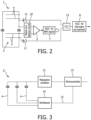
- Fig. 1 schematically depicts a system for the detection of vital signs comprising a radio frequency (RF) transmit-receive coil 1 with a vital signs detector 3 according to an embodiment of the invention.
- the conductor 4 of the radio frequency (RF) transmit-receive coil 1 forms a capacitive electrode with a coupling to the body which is in the order of 5-20 pF.
- the induced ECG signal can be measured as change in the capacitance. For example, a voltage signal is measured over the capacitance and amplified via the high impedance preamplifier 5. Additionaly the capacitance can be modulated by the motion of the body. Having a RF coil array 18, each individual measured signal depends on the local motion and local ECG signal.
- the amplified signal is further digitally processed e.g. via a FPGA unit 8.
- the MRI signal of RF transmit-receive coil 1 is received by the resonant coil circuit and amplified by a RF preamplifier 2. Due to the high impedance of the ECG preamplifier 5 the RF signal is not disturbed.
- the RF transmit-receive coil signal is further digitized and can be used for correction and calibration of the ECG signal, e.g. to remove motion induced artefacts.
- the capacitive vital signs signals and the MRI signals are processed in different frequency spaces. Therefore, in an embodiment of the invention two separate ADC channels 6, 7 may be provided.
- the output of the ADCs is fed to a signal processing device 8.
- the signal processing device 8 can be e.g. a software defined radio (SDR).
- SDR software defined radio
- the signal processing device 8 can be used e.g. for the correction of motion artefacts in the MRI signal by the vital signs signals.
- An interface 9 e.g. an optical interface, controls the communication of the signal processing device 8 with other components of the MRI system.
- the capacitive sensor signal can be transformed (or modulate a) to a pilot tone and received via the MRI receiver or by separate receiver at a different frequency.
- the detection of motion e.g. by breathing or heart beat is one application of the vital signs detector 3, additionally the capacitive vital signs signals can be simultaneously processed by other vital signs detectors such as cameras or RADAR sensors.
- Fig. 2 schematically depicts a system for the detection of vital signs comprising a radio frequency (RF) transmit-receive coil 1 with a vital signs detector 3 according to another embodiment of the invention.
- RF radio frequency
- the RF transmit-receive coil 1 is shown with four capacitive conductors 4 forming the capacitive vital signs detector 3.
- the conductors 4 increase the capacitance for the ECG signal, while the MRI coil resonance is determined by the loop conductor and the lumped capacitors.
- the MRI signals are received by electrically conducting coil elements of the RF transmit-receive coil 1 and fed to a match and detune circuit 11, amplified by a RF amplifier 2 and further fed to an analog-to-digital converter (ADC) 7.
- ADC analog-to-digital converter
- the capacitive vital signs signals are received by the capacitive conductors and fed via two diodes 11 to a relaxation oscillator 12 or a microcontroller for the detection of the capacitive vital signs signals.
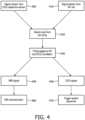
- Fig. 3 schematically depicts a part of a system for the detection of vital signs according to another embodiment of the invention.
- several electrically conducting coil elements 4 of the RF transmit-receive coil 1 forming vital signs detectors 3 can be foreseen.
- a multiplexer 14 is provided which is controlled, for example, by means of a microcontroller 13 by a control signal 15.
- a relaxation oscillator 12 can be provided for the detection of the vital signs signals.
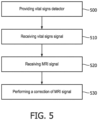
- Fig. 4 schematically depicts a flow chart of the signal stream of the vital signs detector 3 and the RF transmit-receive coil 1 according to an embodiment of the invention.
- the vital signs signal from the vital signs detector 3 is analyzed in step 400.
- the MRI signal from the RF transmit-receive coil 1 is analyzed in step 410.
- the best signal is identified either from the vital signs detector 3 or the RF transmit-receive coil 1.
- a signal processing device 8 e.g. a software defined radio (SDR) is used for generating a correlation of the signal in step 430.
- An improved trigger signal can then be generated from the vital sign signal 450 for improved control of the MRI signal in step 470, e.g. using the correlation of both signals.
- the MRI signal 440 can also be improved using the vital signs signal.
- the overall signal quality can be improved by setting a range of interest, which also improves the MRI reconstruction in step 460.
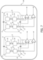
- Fig. 5 shows a flowchart of a method for operating a system for the detection of vital signs in accordance with an embodiment of the invention.
- the method starts with step 500 in which a radio frequency (RF) transmit-receive coil 1 comprising a vital signs detector 3 is provided, wherein the radio frequency (RF) transmit-receive coil 1 and the vital signs detector 3 form a magnetic resonance (MR) imaging coil array.
- RF radio frequency
- Step 510 at least one vital signs signal is received from the vital signs detector 3.
- step 520 at least one MRI signal is received from the radio frequency (RF) transmit-receive coil 1.
- RF radio frequency
- step 530 a correction of the MRI signal based on the vital signs signal is performed.
- Fig. 6 shows vital signs detector patches 16 with a RF transmit-receive coil 1 and impedance circuits 17 in accordance with an embodiment of the invention.
- the additional electrically conducting coil elements 4 forming the vital signs detectors 3 can be formed as patches 16 and combined with the RF transmit-receive coil 1.
- the patches can be e.g. ECG patches with electrocardiography (ECG) sensors the sensors being adapted for receiving ECG signals.
- ECG electrocardiography
- Several patches 16 can be located inside the coil circumference or partly under the coil. The patches 16 are separated from each other in order to prevent B1 shielding effects from the excitation field of the MR body transmit coil.
- the individual patches 16 are connected via impedance circuits 17.
- the impedance circuits 17 can be RF chokes or parallel resonant circuits with a high impedance at the MRI frequency and a low impedance at frequencies for ECG and breathing.
- the signals are amplified and processed separately by different optimized amplifiers 2, 5 e.g. low noise amplifiers (LNA).
- LNA low noise amplifiers
- Fig. 7 shows a RF coil array 18 with individual hybrid RF transmit-receive coils 1 and vital signs detector patches 16 in accordance with an embodiment of the invention.
- Each coil 1 does see an individual part of the human body.
- the individual signals of the vital signs detector patches 16 can be selected e.g. using a multiplexer.
- radio frequency (RF) transmit-receive coil 1 RF amplifier 2 capacitive vital signs detector 3 electrically conducting coil element 4 capacitive vital signs sensor amplifier 5 ADC for vital signs signal 6 ADC for MRI signal 7 signal processing unit 8 interface 9 match and detune circuit 10 diode 11 relaxation oscillator 12 microcontroller 13 multiplexer 14 control signal 15 vital signs detector patch 16 impedance circuit 17 RF coil array 18
- RF radio frequency
Landscapes
- Health & Medical Sciences (AREA)
- Life Sciences & Earth Sciences (AREA)
- Physics & Mathematics (AREA)
- Engineering & Computer Science (AREA)
- Biophysics (AREA)
- General Health & Medical Sciences (AREA)
- Public Health (AREA)
- Veterinary Medicine (AREA)
- Heart & Thoracic Surgery (AREA)
- Medical Informatics (AREA)
- Molecular Biology (AREA)
- Surgery (AREA)
- Animal Behavior & Ethology (AREA)
- Pathology (AREA)
- Biomedical Technology (AREA)
- Nuclear Medicine, Radiotherapy & Molecular Imaging (AREA)
- Physiology (AREA)
- Pulmonology (AREA)
- High Energy & Nuclear Physics (AREA)
- General Physics & Mathematics (AREA)
- Radiology & Medical Imaging (AREA)
- Condensed Matter Physics & Semiconductors (AREA)
- Cardiology (AREA)
- Signal Processing (AREA)
- Power Engineering (AREA)
- Artificial Intelligence (AREA)
- Computer Vision & Pattern Recognition (AREA)
- Psychiatry (AREA)
- Magnetic Resonance Imaging Apparatus (AREA)
- Measurement And Recording Of Electrical Phenomena And Electrical Characteristics Of The Living Body (AREA)
- Microelectronics & Electronic Packaging (AREA)
Claims (13)
- Bobine d'émission-réception radiofréquence (RF) pour un système d'imagerie par résonance magnétique (MR), la bobine d'émission-réception RF comprenant un détecteur de signes vitaux (3) pour la détection des signes vitaux d'un patient dans le système d'imagerie par résonance magnétique (MR), dans lequel le détecteur de signes vitaux (3) est intégré dans la bobine d'émission-réception RF (1), dans lequel une paire d'éléments de bobine électriquement conducteurs (4) de la bobine d'émission-réception RF (1) forme le détecteur de signes vitaux (3), dans lequel le détecteur de signes vitaux (3) est un détecteur capacitif de signes vitaux (3), le détecteur capacitif de signes vitaux (3) étant un capteur d'électrocardiographie (ECG) adapté pour recevoir des signaux ECG.
- Bobine d'émission-réception radiofréquence (RF) selon la revendication 1, dans laquelle la paire d'éléments de bobine électriquement conducteurs (4) de la bobine d'émission-réception RF (1) formant le détecteur de signes vitaux (3) est recouverte d'un matériau ayant une permittivité élevée.
- Bobine d'émission-réception radiofréquence (RF) selon l'une quelconque des revendications précédentes, dans laquelle le détecteur capacitif de signes vitaux (3) et la bobine d'émission-réception RF (1) étant adaptés pour traiter le signal capacitif de signes vitaux et un signal MRI acquis par la bobine d'émission-réception RF (1) dans différents espaces de fréquence.
- Bobine d'émission-réception radiofréquence (RF) selon l'une quelconque des revendications précédentes, dans laquelle le détecteur de signes vitaux (3) est disposé sous un support de patient d'un système d'imagerie par résonance magnétique (MR).
- Système pour la détection de signes vitaux d'un patient dans un système d'imagerie par résonance magnétique (MR), le système comprenant: une bobine d'émission-réception radiofréquence (RF) (1) avec un détecteur de signes vitaux (3) selon l'une quelconque des revendications 1 à 4, le système comprenant en outre un préamplificateur de sortie (5) pour amplifier les signaux capacitifs de signes vitaux, dans lequel la paire d'éléments de bobine électriquement conducteurs (4) est couplée au préamplificateur de sortie (5), le système comprenant en outre un processeur de signal numérique (8), dans lequel le processeur de signal numérique (8) est adapté pour traiter davantage le signal amplifié signaux de signes vitaux capacitifs.
- Système selon la revendication 5, dans lequel le processeur de signal numérique (8) est une radio définie par logiciel (SDR).
- Système selon la revendication 5 ou 6, comprenant un oscillateur de relaxation (12) et/ou un microcontrôleur (13) pour la détection capacitive des signaux de signes vitaux.
- Système selon l'une quelconque des revendications 5 à 7, comprenant un multiplexeur pour commuter entre différentes paires d'éléments de bobine électriquement conducteurs (4) de la bobine d'émission-réception RF (1) formant le détecteur de signes vitaux (3).
- Procédé pour faire fonctionner le système pour la détection de signes vitaux d'un patient dans un système d'imagerie par résonance magnétique (MR) selon la revendication 4, comprenant les étapes suivantes:- fournir une bobine d'émission-réception radiofréquence (RF) (1) comprenant un détecteur de signes vitaux (3), la bobine d'émission-réception radiofréquence (RF) (1) et le détecteur de signes vitaux (3) formant une résonance magnétique (MR) réseau de bobines d'imagerie,- recevoir au moins un signal de signes vitaux provenant du détecteur de signes vitaux (3),- recevoir au moins un signal MRI provenant de la bobine d'émission-réception radiofréquence (RF) (1),- effectuer une correction du signal MRI sur la base du signal de signes vitaux.
- Procédé pour faire fonctionner le système selon la revendication 9, caractérisé en ce que l'étape consistant à effectuer une correction du signal MRI basée sur le signal de signes vitaux comprend une correction basée sur un algorithme d'apprentissage profond.
- Système d'imagerie par résonance magnétique (MR) comprenant un système pour la détection de signes vitaux d'un patient selon les revendications 1 à 8.
- Progiciel pour un système d'imagerie par résonance magnétique (MR), dans lequel le progiciel contient des instructions pour commander un système pour la détection de signes vitaux d'un patient dans un système d'imagerie par résonance magnétique (MR) selon le procédé des revendications 9 à 10.
- Progiciel pour mettre à niveau un système d'imagerie par résonance magnétique (MR), le progiciel contenant des instructions pour commander un système récepteur radiofréquence (RF) (1) comprenant un détecteur de signes vitaux (3) selon le procédé des revendications 9 à 10.
Applications Claiming Priority (2)
| Application Number | Priority Date | Filing Date | Title |
|---|---|---|---|
| EP19219362.1A EP3841972A1 (fr) | 2019-12-23 | 2019-12-23 | Bobine rf intégrant un détecteur de signes vitaux |
| PCT/EP2020/087584 WO2021130203A1 (fr) | 2019-12-23 | 2020-12-22 | Bobine rf comprenant un détecteur de signes vitaux intégré |
Publications (2)
| Publication Number | Publication Date |
|---|---|
| EP4081111A1 EP4081111A1 (fr) | 2022-11-02 |
| EP4081111B1 true EP4081111B1 (fr) | 2024-03-20 |
Family
ID=69005590
Family Applications (2)
| Application Number | Title | Priority Date | Filing Date |
|---|---|---|---|
| EP19219362.1A Withdrawn EP3841972A1 (fr) | 2019-12-23 | 2019-12-23 | Bobine rf intégrant un détecteur de signes vitaux |
| EP20838544.3A Active EP4081111B1 (fr) | 2019-12-23 | 2020-12-22 | Bobine rf comprenant un détecteur de signes vitaux intégré |
Family Applications Before (1)
| Application Number | Title | Priority Date | Filing Date |
|---|---|---|---|
| EP19219362.1A Withdrawn EP3841972A1 (fr) | 2019-12-23 | 2019-12-23 | Bobine rf intégrant un détecteur de signes vitaux |
Country Status (5)
| Country | Link |
|---|---|
| US (1) | US11850033B2 (fr) |
| EP (2) | EP3841972A1 (fr) |
| JP (1) | JP7670059B2 (fr) |
| CN (1) | CN114867412B (fr) |
| WO (1) | WO2021130203A1 (fr) |
Families Citing this family (5)
| Publication number | Priority date | Publication date | Assignee | Title |
|---|---|---|---|---|
| US20230141400A1 (en) * | 2021-11-05 | 2023-05-11 | Zachary Owen Rebro | Vitals Monitoring Handcuff Apparatus |
| EP4253979A1 (fr) * | 2022-03-28 | 2023-10-04 | Koninklijke Philips N.V. | Réseau de bobine de récepteur à résonance magnétique doté d'un capteur de nud |
| EP4684224A1 (fr) * | 2023-03-22 | 2026-01-28 | Koninklijke Philips N.V. | Réseau de bobines réceptrices à résonance magnétique avec transducteur ultrasonore intégré |
| CN116421166B (zh) * | 2023-04-25 | 2026-01-09 | 北京理工大学 | 一种感知人体内信号的智能微型机器人及加工方法 |
| EP4481420A1 (fr) | 2023-06-19 | 2024-12-25 | Koninklijke Philips N.V. | Système d'examen par résonance thouhmagnétique avec un capteur facile à entretenir |
Family Cites Families (14)
| Publication number | Priority date | Publication date | Assignee | Title |
|---|---|---|---|---|
| EP0168691A1 (fr) * | 1984-07-05 | 1986-01-22 | Siemens Aktiengesellschaft | Dispositif de mesure sans contact des mouvements d'un organe |
| JP4072879B2 (ja) * | 1998-11-26 | 2008-04-09 | 株式会社日立メディコ | 核磁気共鳴撮影装置 |
| JP4672119B2 (ja) * | 2000-08-11 | 2011-04-20 | 株式会社東芝 | 核磁気共鳴映像装置用高周波コイル及び核磁気共鳴映像装置 |
| US8294588B2 (en) | 2006-05-12 | 2012-10-23 | Koninklijke Philips Electronics N.V. | Battery system for MRI compatible wireless patient monitor |
| JP2010522009A (ja) * | 2007-03-20 | 2010-07-01 | コーニンクレッカ フィリップス エレクトロニクス エヌ ヴィ | 磁気共鳴撮像システム及び方法 |
| JP2009106573A (ja) * | 2007-10-31 | 2009-05-21 | Ge Medical Systems Global Technology Co Llc | Mri装置 |
| US8903482B2 (en) * | 2009-09-14 | 2014-12-02 | Koninklijke Philips N.V. | Apparatus and method for non-invasive intracardiac electrocardiography using MPI |
| WO2011033422A1 (fr) * | 2009-09-17 | 2011-03-24 | Koninklijke Philips Electronics N.V. | Système d'imagerie par résonance magnétique comprenant des capteurs physiologiques |
| US9714993B2 (en) * | 2013-01-11 | 2017-07-25 | Toshiba Medical Systems Corporation | Determination of specific absorption rate (SAR) in magnetic resonance imaging (MRI) |
| CN105190342B (zh) * | 2013-03-13 | 2018-01-30 | 皇家飞利浦有限公司 | 用于磁共振成像的多元件rf发射线圈 |
| DE102013219117A1 (de) * | 2013-09-24 | 2015-03-26 | Siemens Aktiengesellschaft | Korrektur von kapazitiv aufgenommenen EKG-Signalen in Verbindung Messungen mit einem medizinischen bildgebenden Untersuchungsgerät |
| US9320447B2 (en) * | 2014-02-07 | 2016-04-26 | Biosense Webster (Israel) Ltd. | Dynamic cancellation of MRI sequencing noise appearing in an ECG signal |
| EP3398510A1 (fr) * | 2017-05-04 | 2018-11-07 | Koninklijke Philips N.V. | Système et procédé de focalisation dynamique sur le coeur et/ou les poumons par accord de fréquence et analyse de phase d'impédance et/ou variations de magnitude |
| CN209673975U (zh) * | 2019-01-29 | 2019-11-22 | 上海联影医疗科技有限公司 | 磁共振线圈组件及磁共振系统 |
-
2019
- 2019-12-23 EP EP19219362.1A patent/EP3841972A1/fr not_active Withdrawn
-
2020
- 2020-12-22 US US17/788,318 patent/US11850033B2/en active Active
- 2020-12-22 JP JP2022537123A patent/JP7670059B2/ja active Active
- 2020-12-22 CN CN202080089775.4A patent/CN114867412B/zh active Active
- 2020-12-22 WO PCT/EP2020/087584 patent/WO2021130203A1/fr not_active Ceased
- 2020-12-22 EP EP20838544.3A patent/EP4081111B1/fr active Active
Also Published As
| Publication number | Publication date |
|---|---|
| JP2023506912A (ja) | 2023-02-20 |
| EP4081111A1 (fr) | 2022-11-02 |
| US20230037196A1 (en) | 2023-02-02 |
| JP7670059B2 (ja) | 2025-04-30 |
| WO2021130203A1 (fr) | 2021-07-01 |
| US11850033B2 (en) | 2023-12-26 |
| CN114867412B (zh) | 2025-03-25 |
| CN114867412A (zh) | 2022-08-05 |
| EP3841972A1 (fr) | 2021-06-30 |
Similar Documents
| Publication | Publication Date | Title |
|---|---|---|
| EP4081111B1 (fr) | Bobine rf comprenant un détecteur de signes vitaux intégré | |
| JP5937757B2 (ja) | 医療用途のための磁界計測器 | |
| US20130116544A1 (en) | Dual pressure sensor signal chain to remove mutually-coupled mri interference | |
| EP2854631B1 (fr) | Câble de sûreté pour résonance magnétique pour mesures de biopotentiels | |
| EP3248024B1 (fr) | Règlage d'impedance automatique d'une antenne rf à voies multiples | |
| EP2332463A1 (fr) | Appareil et méthode de tomographie à induction magnétique | |
| JP2015517373A (ja) | 生体電位測定に関する磁気共鳴安全な電極 | |
| US10048347B2 (en) | Power measurement on magnetic resonance imaging coil at different frequency than Larmor frequency | |
| CN103293497B (zh) | 用于屏蔽磁共振信号的局部屏蔽装置和方法 | |
| US11467236B2 (en) | Biological information monitoring apparatus and MRI apparatus | |
| CN112998718A (zh) | 抑制在测量生物电信号时电极上的回声作用 | |
| US20210322697A1 (en) | Measuring device and method for determining at least one respiratory parameter | |
| US9945916B2 (en) | Temperature monitoring of local coils | |
| CN219594618U (zh) | 构成为结合磁共振设备使用的心电图设备和磁共振设备 | |
| EP4500207B1 (fr) | Réseau de bobine de récepteur à résonance magnétique doté d'un capteur de nud | |
| CN114533075A (zh) | 干扰信号补偿装置、差分电压测量系统和x射线成像系统 | |
| CN116458891A (zh) | 用于与磁共振设备结合使用的心电图设备 |
Legal Events
| Date | Code | Title | Description |
|---|---|---|---|
| STAA | Information on the status of an ep patent application or granted ep patent |
Free format text: STATUS: UNKNOWN |
|
| STAA | Information on the status of an ep patent application or granted ep patent |
Free format text: STATUS: THE INTERNATIONAL PUBLICATION HAS BEEN MADE |
|
| PUAI | Public reference made under article 153(3) epc to a published international application that has entered the european phase |
Free format text: ORIGINAL CODE: 0009012 |
|
| STAA | Information on the status of an ep patent application or granted ep patent |
Free format text: STATUS: REQUEST FOR EXAMINATION WAS MADE |
|
| 17P | Request for examination filed |
Effective date: 20220725 |
|
| AK | Designated contracting states |
Kind code of ref document: A1 Designated state(s): AL AT BE BG CH CY CZ DE DK EE ES FI FR GB GR HR HU IE IS IT LI LT LU LV MC MK MT NL NO PL PT RO RS SE SI SK SM TR |
|
| DAV | Request for validation of the european patent (deleted) | ||
| DAX | Request for extension of the european patent (deleted) | ||
| GRAP | Despatch of communication of intention to grant a patent |
Free format text: ORIGINAL CODE: EPIDOSNIGR1 |
|
| STAA | Information on the status of an ep patent application or granted ep patent |
Free format text: STATUS: GRANT OF PATENT IS INTENDED |
|
| INTG | Intention to grant announced |
Effective date: 20231025 |
|
| GRAS | Grant fee paid |
Free format text: ORIGINAL CODE: EPIDOSNIGR3 |
|
| GRAA | (expected) grant |
Free format text: ORIGINAL CODE: 0009210 |
|
| STAA | Information on the status of an ep patent application or granted ep patent |
Free format text: STATUS: THE PATENT HAS BEEN GRANTED |
|
| AK | Designated contracting states |
Kind code of ref document: B1 Designated state(s): AL AT BE BG CH CY CZ DE DK EE ES FI FR GB GR HR HU IE IS IT LI LT LU LV MC MK MT NL NO PL PT RO RS SE SI SK SM TR |
|
| REG | Reference to a national code |
Ref country code: GB Ref legal event code: FG4D |
|
| REG | Reference to a national code |
Ref country code: DE Ref legal event code: R084 Ref document number: 602020027661 Country of ref document: DE Ref country code: CH Ref legal event code: EP |
|
| REG | Reference to a national code |
Ref country code: DE Ref legal event code: R096 Ref document number: 602020027661 Country of ref document: DE |
|
| REG | Reference to a national code |
Ref country code: IE Ref legal event code: FG4D |
|
| PG25 | Lapsed in a contracting state [announced via postgrant information from national office to epo] |
Ref country code: LT Free format text: LAPSE BECAUSE OF FAILURE TO SUBMIT A TRANSLATION OF THE DESCRIPTION OR TO PAY THE FEE WITHIN THE PRESCRIBED TIME-LIMIT Effective date: 20240320 |
|
| REG | Reference to a national code |
Ref country code: LT Ref legal event code: MG9D |
|
| PG25 | Lapsed in a contracting state [announced via postgrant information from national office to epo] |
Ref country code: GR Free format text: LAPSE BECAUSE OF FAILURE TO SUBMIT A TRANSLATION OF THE DESCRIPTION OR TO PAY THE FEE WITHIN THE PRESCRIBED TIME-LIMIT Effective date: 20240621 |
|
| PG25 | Lapsed in a contracting state [announced via postgrant information from national office to epo] |
Ref country code: RS Free format text: LAPSE BECAUSE OF FAILURE TO SUBMIT A TRANSLATION OF THE DESCRIPTION OR TO PAY THE FEE WITHIN THE PRESCRIBED TIME-LIMIT Effective date: 20240620 Ref country code: HR Free format text: LAPSE BECAUSE OF FAILURE TO SUBMIT A TRANSLATION OF THE DESCRIPTION OR TO PAY THE FEE WITHIN THE PRESCRIBED TIME-LIMIT Effective date: 20240320 |
|
| REG | Reference to a national code |
Ref country code: NL Ref legal event code: MP Effective date: 20240320 |
|
| PG25 | Lapsed in a contracting state [announced via postgrant information from national office to epo] |
Ref country code: RS Free format text: LAPSE BECAUSE OF FAILURE TO SUBMIT A TRANSLATION OF THE DESCRIPTION OR TO PAY THE FEE WITHIN THE PRESCRIBED TIME-LIMIT Effective date: 20240620 Ref country code: NO Free format text: LAPSE BECAUSE OF FAILURE TO SUBMIT A TRANSLATION OF THE DESCRIPTION OR TO PAY THE FEE WITHIN THE PRESCRIBED TIME-LIMIT Effective date: 20240620 Ref country code: LT Free format text: LAPSE BECAUSE OF FAILURE TO SUBMIT A TRANSLATION OF THE DESCRIPTION OR TO PAY THE FEE WITHIN THE PRESCRIBED TIME-LIMIT Effective date: 20240320 Ref country code: HR Free format text: LAPSE BECAUSE OF FAILURE TO SUBMIT A TRANSLATION OF THE DESCRIPTION OR TO PAY THE FEE WITHIN THE PRESCRIBED TIME-LIMIT Effective date: 20240320 Ref country code: GR Free format text: LAPSE BECAUSE OF FAILURE TO SUBMIT A TRANSLATION OF THE DESCRIPTION OR TO PAY THE FEE WITHIN THE PRESCRIBED TIME-LIMIT Effective date: 20240621 Ref country code: FI Free format text: LAPSE BECAUSE OF FAILURE TO SUBMIT A TRANSLATION OF THE DESCRIPTION OR TO PAY THE FEE WITHIN THE PRESCRIBED TIME-LIMIT Effective date: 20240320 Ref country code: BG Free format text: LAPSE BECAUSE OF FAILURE TO SUBMIT A TRANSLATION OF THE DESCRIPTION OR TO PAY THE FEE WITHIN THE PRESCRIBED TIME-LIMIT Effective date: 20240320 |
|
| REG | Reference to a national code |
Ref country code: AT Ref legal event code: MK05 Ref document number: 1667082 Country of ref document: AT Kind code of ref document: T Effective date: 20240320 |
|
| PG25 | Lapsed in a contracting state [announced via postgrant information from national office to epo] |
Ref country code: SE Free format text: LAPSE BECAUSE OF FAILURE TO SUBMIT A TRANSLATION OF THE DESCRIPTION OR TO PAY THE FEE WITHIN THE PRESCRIBED TIME-LIMIT Effective date: 20240320 Ref country code: LV Free format text: LAPSE BECAUSE OF FAILURE TO SUBMIT A TRANSLATION OF THE DESCRIPTION OR TO PAY THE FEE WITHIN THE PRESCRIBED TIME-LIMIT Effective date: 20240320 |
|
| PG25 | Lapsed in a contracting state [announced via postgrant information from national office to epo] |
Ref country code: NL Free format text: LAPSE BECAUSE OF FAILURE TO SUBMIT A TRANSLATION OF THE DESCRIPTION OR TO PAY THE FEE WITHIN THE PRESCRIBED TIME-LIMIT Effective date: 20240320 |
|
| PG25 | Lapsed in a contracting state [announced via postgrant information from national office to epo] |
Ref country code: NL Free format text: LAPSE BECAUSE OF FAILURE TO SUBMIT A TRANSLATION OF THE DESCRIPTION OR TO PAY THE FEE WITHIN THE PRESCRIBED TIME-LIMIT Effective date: 20240320 |
|
| PG25 | Lapsed in a contracting state [announced via postgrant information from national office to epo] |
Ref country code: IS Free format text: LAPSE BECAUSE OF FAILURE TO SUBMIT A TRANSLATION OF THE DESCRIPTION OR TO PAY THE FEE WITHIN THE PRESCRIBED TIME-LIMIT Effective date: 20240720 |
|
| PG25 | Lapsed in a contracting state [announced via postgrant information from national office to epo] |
Ref country code: SM Free format text: LAPSE BECAUSE OF FAILURE TO SUBMIT A TRANSLATION OF THE DESCRIPTION OR TO PAY THE FEE WITHIN THE PRESCRIBED TIME-LIMIT Effective date: 20240320 Ref country code: PT Free format text: LAPSE BECAUSE OF FAILURE TO SUBMIT A TRANSLATION OF THE DESCRIPTION OR TO PAY THE FEE WITHIN THE PRESCRIBED TIME-LIMIT Effective date: 20240722 |
|
| PG25 | Lapsed in a contracting state [announced via postgrant information from national office to epo] |
Ref country code: ES Free format text: LAPSE BECAUSE OF FAILURE TO SUBMIT A TRANSLATION OF THE DESCRIPTION OR TO PAY THE FEE WITHIN THE PRESCRIBED TIME-LIMIT Effective date: 20240320 |
|
| PG25 | Lapsed in a contracting state [announced via postgrant information from national office to epo] |
Ref country code: EE Free format text: LAPSE BECAUSE OF FAILURE TO SUBMIT A TRANSLATION OF THE DESCRIPTION OR TO PAY THE FEE WITHIN THE PRESCRIBED TIME-LIMIT Effective date: 20240320 Ref country code: CZ Free format text: LAPSE BECAUSE OF FAILURE TO SUBMIT A TRANSLATION OF THE DESCRIPTION OR TO PAY THE FEE WITHIN THE PRESCRIBED TIME-LIMIT Effective date: 20240320 |
|
| PG25 | Lapsed in a contracting state [announced via postgrant information from national office to epo] |
Ref country code: AT Free format text: LAPSE BECAUSE OF FAILURE TO SUBMIT A TRANSLATION OF THE DESCRIPTION OR TO PAY THE FEE WITHIN THE PRESCRIBED TIME-LIMIT Effective date: 20240320 |
|
| PG25 | Lapsed in a contracting state [announced via postgrant information from national office to epo] |
Ref country code: PL Free format text: LAPSE BECAUSE OF FAILURE TO SUBMIT A TRANSLATION OF THE DESCRIPTION OR TO PAY THE FEE WITHIN THE PRESCRIBED TIME-LIMIT Effective date: 20240320 |
|
| PG25 | Lapsed in a contracting state [announced via postgrant information from national office to epo] |
Ref country code: SK Free format text: LAPSE BECAUSE OF FAILURE TO SUBMIT A TRANSLATION OF THE DESCRIPTION OR TO PAY THE FEE WITHIN THE PRESCRIBED TIME-LIMIT Effective date: 20240320 |
|
| PG25 | Lapsed in a contracting state [announced via postgrant information from national office to epo] |
Ref country code: SM Free format text: LAPSE BECAUSE OF FAILURE TO SUBMIT A TRANSLATION OF THE DESCRIPTION OR TO PAY THE FEE WITHIN THE PRESCRIBED TIME-LIMIT Effective date: 20240320 Ref country code: SK Free format text: LAPSE BECAUSE OF FAILURE TO SUBMIT A TRANSLATION OF THE DESCRIPTION OR TO PAY THE FEE WITHIN THE PRESCRIBED TIME-LIMIT Effective date: 20240320 Ref country code: RO Free format text: LAPSE BECAUSE OF FAILURE TO SUBMIT A TRANSLATION OF THE DESCRIPTION OR TO PAY THE FEE WITHIN THE PRESCRIBED TIME-LIMIT Effective date: 20240320 Ref country code: PT Free format text: LAPSE BECAUSE OF FAILURE TO SUBMIT A TRANSLATION OF THE DESCRIPTION OR TO PAY THE FEE WITHIN THE PRESCRIBED TIME-LIMIT Effective date: 20240722 Ref country code: PL Free format text: LAPSE BECAUSE OF FAILURE TO SUBMIT A TRANSLATION OF THE DESCRIPTION OR TO PAY THE FEE WITHIN THE PRESCRIBED TIME-LIMIT Effective date: 20240320 Ref country code: IS Free format text: LAPSE BECAUSE OF FAILURE TO SUBMIT A TRANSLATION OF THE DESCRIPTION OR TO PAY THE FEE WITHIN THE PRESCRIBED TIME-LIMIT Effective date: 20240720 Ref country code: ES Free format text: LAPSE BECAUSE OF FAILURE TO SUBMIT A TRANSLATION OF THE DESCRIPTION OR TO PAY THE FEE WITHIN THE PRESCRIBED TIME-LIMIT Effective date: 20240320 Ref country code: EE Free format text: LAPSE BECAUSE OF FAILURE TO SUBMIT A TRANSLATION OF THE DESCRIPTION OR TO PAY THE FEE WITHIN THE PRESCRIBED TIME-LIMIT Effective date: 20240320 Ref country code: CZ Free format text: LAPSE BECAUSE OF FAILURE TO SUBMIT A TRANSLATION OF THE DESCRIPTION OR TO PAY THE FEE WITHIN THE PRESCRIBED TIME-LIMIT Effective date: 20240320 Ref country code: AT Free format text: LAPSE BECAUSE OF FAILURE TO SUBMIT A TRANSLATION OF THE DESCRIPTION OR TO PAY THE FEE WITHIN THE PRESCRIBED TIME-LIMIT Effective date: 20240320 |
|
| PG25 | Lapsed in a contracting state [announced via postgrant information from national office to epo] |
Ref country code: IT Free format text: LAPSE BECAUSE OF FAILURE TO SUBMIT A TRANSLATION OF THE DESCRIPTION OR TO PAY THE FEE WITHIN THE PRESCRIBED TIME-LIMIT Effective date: 20240320 |
|
| REG | Reference to a national code |
Ref country code: DE Ref legal event code: R097 Ref document number: 602020027661 Country of ref document: DE |
|
| PG25 | Lapsed in a contracting state [announced via postgrant information from national office to epo] |
Ref country code: IT Free format text: LAPSE BECAUSE OF FAILURE TO SUBMIT A TRANSLATION OF THE DESCRIPTION OR TO PAY THE FEE WITHIN THE PRESCRIBED TIME-LIMIT Effective date: 20240320 |
|
| PG25 | Lapsed in a contracting state [announced via postgrant information from national office to epo] |
Ref country code: DK Free format text: LAPSE BECAUSE OF FAILURE TO SUBMIT A TRANSLATION OF THE DESCRIPTION OR TO PAY THE FEE WITHIN THE PRESCRIBED TIME-LIMIT Effective date: 20240320 |
|
| PLBE | No opposition filed within time limit |
Free format text: ORIGINAL CODE: 0009261 |
|
| STAA | Information on the status of an ep patent application or granted ep patent |
Free format text: STATUS: NO OPPOSITION FILED WITHIN TIME LIMIT |
|
| PG25 | Lapsed in a contracting state [announced via postgrant information from national office to epo] |
Ref country code: DK Free format text: LAPSE BECAUSE OF FAILURE TO SUBMIT A TRANSLATION OF THE DESCRIPTION OR TO PAY THE FEE WITHIN THE PRESCRIBED TIME-LIMIT Effective date: 20240320 |
|
| 26N | No opposition filed |
Effective date: 20241223 |
|
| PG25 | Lapsed in a contracting state [announced via postgrant information from national office to epo] |
Ref country code: SI Free format text: LAPSE BECAUSE OF FAILURE TO SUBMIT A TRANSLATION OF THE DESCRIPTION OR TO PAY THE FEE WITHIN THE PRESCRIBED TIME-LIMIT Effective date: 20240320 |
|
| PG25 | Lapsed in a contracting state [announced via postgrant information from national office to epo] |
Ref country code: MC Free format text: LAPSE BECAUSE OF FAILURE TO SUBMIT A TRANSLATION OF THE DESCRIPTION OR TO PAY THE FEE WITHIN THE PRESCRIBED TIME-LIMIT Effective date: 20240320 |
|
| REG | Reference to a national code |
Ref country code: CH Ref legal event code: PL |
|
| PG25 | Lapsed in a contracting state [announced via postgrant information from national office to epo] |
Ref country code: LU Free format text: LAPSE BECAUSE OF NON-PAYMENT OF DUE FEES Effective date: 20241222 |
|
| GBPC | Gb: european patent ceased through non-payment of renewal fee |
Effective date: 20241222 |
|
| REG | Reference to a national code |
Ref country code: BE Ref legal event code: MM Effective date: 20241231 |
|
| PG25 | Lapsed in a contracting state [announced via postgrant information from national office to epo] |
Ref country code: GB Free format text: LAPSE BECAUSE OF NON-PAYMENT OF DUE FEES Effective date: 20241222 Ref country code: BE Free format text: LAPSE BECAUSE OF NON-PAYMENT OF DUE FEES Effective date: 20241231 |
|
| PG25 | Lapsed in a contracting state [announced via postgrant information from national office to epo] |
Ref country code: CH Free format text: LAPSE BECAUSE OF NON-PAYMENT OF DUE FEES Effective date: 20241231 |
|
| PG25 | Lapsed in a contracting state [announced via postgrant information from national office to epo] |
Ref country code: IE Free format text: LAPSE BECAUSE OF NON-PAYMENT OF DUE FEES Effective date: 20241222 |
|
| PGFP | Annual fee paid to national office [announced via postgrant information from national office to epo] |
Ref country code: FR Payment date: 20251222 Year of fee payment: 6 |
|
| PGFP | Annual fee paid to national office [announced via postgrant information from national office to epo] |
Ref country code: DE Payment date: 20251229 Year of fee payment: 6 |