EP4081277B1 - Druckbehälter, flüssigkeitsmischvorrichtung, flüssigkeitsmischsystem, verfahren zur herstellung einer lösung, steuerungssystem und computerlesbarer programmträger - Google Patents
Druckbehälter, flüssigkeitsmischvorrichtung, flüssigkeitsmischsystem, verfahren zur herstellung einer lösung, steuerungssystem und computerlesbarer programmträger Download PDFInfo
- Publication number
- EP4081277B1 EP4081277B1 EP19957853.5A EP19957853A EP4081277B1 EP 4081277 B1 EP4081277 B1 EP 4081277B1 EP 19957853 A EP19957853 A EP 19957853A EP 4081277 B1 EP4081277 B1 EP 4081277B1
- Authority
- EP
- European Patent Office
- Prior art keywords
- pressure vessel
- liquid
- chamber
- canister
- liquid mixing
- Prior art date
- Legal status (The legal status is an assumption and is not a legal conclusion. Google has not performed a legal analysis and makes no representation as to the accuracy of the status listed.)
- Active
Links
Images


Classifications
-
- F—MECHANICAL ENGINEERING; LIGHTING; HEATING; WEAPONS; BLASTING
- F16—ENGINEERING ELEMENTS AND UNITS; GENERAL MEASURES FOR PRODUCING AND MAINTAINING EFFECTIVE FUNCTIONING OF MACHINES OR INSTALLATIONS; THERMAL INSULATION IN GENERAL
- F16L—PIPES; JOINTS OR FITTINGS FOR PIPES; SUPPORTS FOR PIPES, CABLES OR PROTECTIVE TUBING; MEANS FOR THERMAL INSULATION IN GENERAL
- F16L51/00—Expansion-compensation arrangements for pipe-lines
-
- A—HUMAN NECESSITIES
- A61—MEDICAL OR VETERINARY SCIENCE; HYGIENE
- A61M—DEVICES FOR INTRODUCING MEDIA INTO, OR ONTO, THE BODY; DEVICES FOR TRANSDUCING BODY MEDIA OR FOR TAKING MEDIA FROM THE BODY; DEVICES FOR PRODUCING OR ENDING SLEEP OR STUPOR
- A61M1/00—Suction or pumping devices for medical purposes; Devices for carrying-off, for treatment of, or for carrying-over, body-liquids; Drainage systems
- A61M1/14—Dialysis systems; Artificial kidneys; Blood oxygenators ; Reciprocating systems for treatment of body fluids, e.g. single needle systems for hemofiltration or pheresis
- A61M1/16—Dialysis systems; Artificial kidneys; Blood oxygenators ; Reciprocating systems for treatment of body fluids, e.g. single needle systems for hemofiltration or pheresis with membranes
- A61M1/1654—Dialysates therefor
- A61M1/1656—Apparatus for preparing dialysates
- A61M1/1666—Apparatus for preparing dialysates by dissolving solids
-
- A—HUMAN NECESSITIES
- A61—MEDICAL OR VETERINARY SCIENCE; HYGIENE
- A61M—DEVICES FOR INTRODUCING MEDIA INTO, OR ONTO, THE BODY; DEVICES FOR TRANSDUCING BODY MEDIA OR FOR TAKING MEDIA FROM THE BODY; DEVICES FOR PRODUCING OR ENDING SLEEP OR STUPOR
- A61M1/00—Suction or pumping devices for medical purposes; Devices for carrying-off, for treatment of, or for carrying-over, body-liquids; Drainage systems
- A61M1/14—Dialysis systems; Artificial kidneys; Blood oxygenators ; Reciprocating systems for treatment of body fluids, e.g. single needle systems for hemofiltration or pheresis
- A61M1/16—Dialysis systems; Artificial kidneys; Blood oxygenators ; Reciprocating systems for treatment of body fluids, e.g. single needle systems for hemofiltration or pheresis with membranes
- A61M1/1654—Dialysates therefor
- A61M1/1656—Apparatus for preparing dialysates
- A61M1/1668—Details of containers
-
- A—HUMAN NECESSITIES
- A61—MEDICAL OR VETERINARY SCIENCE; HYGIENE
- A61M—DEVICES FOR INTRODUCING MEDIA INTO, OR ONTO, THE BODY; DEVICES FOR TRANSDUCING BODY MEDIA OR FOR TAKING MEDIA FROM THE BODY; DEVICES FOR PRODUCING OR ENDING SLEEP OR STUPOR
- A61M2205/00—General characteristics of the apparatus
- A61M2205/33—Controlling, regulating or measuring
- A61M2205/3331—Pressure; Flow
- A61M2205/3341—Pressure; Flow stabilising pressure or flow to avoid excessive variation
-
- A—HUMAN NECESSITIES
- A61—MEDICAL OR VETERINARY SCIENCE; HYGIENE
- A61M—DEVICES FOR INTRODUCING MEDIA INTO, OR ONTO, THE BODY; DEVICES FOR TRANSDUCING BODY MEDIA OR FOR TAKING MEDIA FROM THE BODY; DEVICES FOR PRODUCING OR ENDING SLEEP OR STUPOR
- A61M2205/00—General characteristics of the apparatus
- A61M2205/33—Controlling, regulating or measuring
- A61M2205/3331—Pressure; Flow
- A61M2205/3351—Controlling upstream pump pressure
-
- A—HUMAN NECESSITIES
- A61—MEDICAL OR VETERINARY SCIENCE; HYGIENE
- A61M—DEVICES FOR INTRODUCING MEDIA INTO, OR ONTO, THE BODY; DEVICES FOR TRANSDUCING BODY MEDIA OR FOR TAKING MEDIA FROM THE BODY; DEVICES FOR PRODUCING OR ENDING SLEEP OR STUPOR
- A61M2205/00—General characteristics of the apparatus
- A61M2205/82—Internal energy supply devices
- A61M2205/8275—Mechanical
- A61M2205/8281—Mechanical spring operated
-
- A—HUMAN NECESSITIES
- A61—MEDICAL OR VETERINARY SCIENCE; HYGIENE
- A61M—DEVICES FOR INTRODUCING MEDIA INTO, OR ONTO, THE BODY; DEVICES FOR TRANSDUCING BODY MEDIA OR FOR TAKING MEDIA FROM THE BODY; DEVICES FOR PRODUCING OR ENDING SLEEP OR STUPOR
- A61M2206/00—Characteristics of a physical parameter; associated device therefor
- A61M2206/10—Flow characteristics
- A61M2206/22—Flow characteristics eliminating pulsatile flows, e.g. by the provision of a dampening chamber
Definitions
- the disclosure relates to a pressure vessel for liquid mixing, a liquid mixing equipment comprising the pressure vessel, a liquid mixing system comprising the pressure vessel or the liquid mixing equipment, a method for preparing a solution using the pressure vessel, the liquid mixing equipment or the liquid mixing system, a corresponding control system and a corresponding computer readable program carrier.
- the dialysis treatment is a process for purifying blood of a person whose kidney is not working normally.
- the dialysis solution is often prepared just before dialysis sessions.
- solid substance for example in a form of powders, granules or tablets or mixtures thereof is placed in a container and can be dissolved by liquid, for example reverse osmosis (RO) water to obtain a solution which may be a dialysis solution or an intermediate solution for preparing the dialysis solution.
- liquid concentrates like bicarbonate and sodium saturated solution can be prepared online from the corresponding solid substances.
- refilling of the liquid into the container is controlled to obtain a desired solution flow toward a downstream dialysate mixing path.
- the container may be made of rigid or soft plastic material.
- the refilling process can be done by a pressure-controlled method. Specifically, the soft container is first filled with the liquid and followed by refilling cycles based on predetermined upper and lower fluid pressure set points.
- the pressure-controlled method cannot be used for the rigid container in a closed hydraulic system design.
- the liquid in the closed container is dispensed to the dialysate mixing path, excessive pressure change will act on a downstream liquid concentrate pump, which may damage the concentrate pump and lead to a mixing error.
- an object of the present disclosure is to provide a pressure vessel for liquid mixing, a liquid mixing equipment comprising the pressure vessel, a liquid mixing system comprising the pressure vessel or the liquid mixing equipment, a method for preparing a solution using the pressure vessel, the liquid mixing equipment or the liquid mixing system, a corresponding control system and a corresponding computer readable program carrier.
- a pressure vessel for liquid mixing comprising: a housing; a deformable member configured to define a chamber in combination with at least one portion of the housing; an inlet port fluidly communicated with the chamber; an outlet port fluidly communicated with the chamber; an elastic biasing means configured to interact with the deformable member to make a volume of the chamber variable; and an air detection means configured to detect the presence of air within the chamber.
- the deformable member is formed by a flexible diaphragm; and/or the inlet port and the outlet port are disposed opposite to each other.
- the elastic biasing means comprises a spring, preferably a conical coil spring, or is configured in a manner of compressed gas, preferably compressed air; and/or the air detection means comprises a pair of air detection electrodes extending into the chamber.
- an inner space of the chamber is configured to generate a fluid flow for facilitating hygiene control in a cleaning and/or disinfection process; and/or the elastic biasing means is adjustable to regulate the volume of the chamber in operation.
- the inner space of the chamber is compressed by a force of the elastic biasing means to some extent at an initial stage; preferably, the inner space of the chamber is configured to have initially a U-shaped section along a direction of the elastic biasing means acting on the deformable member and extending the inlet port and the outlet port, and a bottom portion of the U-shaped section is defined by the deformable member.
- the air detection means is disposed adjacent to an outer end of a first leg of the U-shaped section; and/or the inlet port is disposed adjacent to a corner between the first leg and the bottom portion of the U-shaped section; and/or the outlet port is disposed adjacent to a middle point of a second leg of the U-shaped section opposite to the first leg.
- a liquid mixing equipment comprising the pressure vessel described above.
- a liquid mixing system comprising the pressure vessel described above or the liquid mixing equipment described above.
- the liquid mixing system further comprises: a canister, in particular a rigid canister, for receiving a substance to be dissolved or diluted by a first liquid to prepare a solution, preferably a saturated solution, wherein the outlet port of the pressure vessel is fluidly connected to the canister; and a mixing chamber fluidly connected to the canister to receive the solution; preferably, the inlet port of the pressure vessel is positioned higher than the outlet port of the pressure vessel in an operation state.
- a canister in particular a rigid canister, for receiving a substance to be dissolved or diluted by a first liquid to prepare a solution, preferably a saturated solution, wherein the outlet port of the pressure vessel is fluidly connected to the canister; and a mixing chamber fluidly connected to the canister to receive the solution; preferably, the inlet port of the pressure vessel is positioned higher than the outlet port of the pressure vessel in an operation state.
- the liquid mixing system further comprises: a first flow path fluidly connected to the inlet port of the pressure vessel to allow for filling the canister with the first liquid via the first flow path and the pressure vessel; and/or a second flow path fluidly connected to the canister to allow for filling the canister with a second liquid; and/or a third flow path fluidly connected to the canister to allow for transferring the solution to the mixing chamber; and/or a fourth flow path fluidly connected to the mixing chamber to supply a third liquid to the mixing chamber.
- the liquid mixing system further comprises: a pressure detection means configured to detect a pressure within the first flow path; a first valve disposed in the first flow path upstream of the pressure detection means; and an air exhausting means fluidly connected to the first flow path between the first valve and the pressure vessel.
- the air exhausting means comprises a second valve and an air outlet; and/or the canister has a top and a bottom in the operation state, and the pressure vessel is fluidly connected to a top inlet port of the canister to allow for filling the canister with the first liquid via the top of the canister.
- the liquid mixing system further comprises a third valve disposed in the second flow path; and/or the second flow path is configured to allow for filling the canister with the second liquid via the bottom of the canister.
- the liquid mixing system further comprises: a solution pump disposed in the third flow path to pump the solution to the mixing chamber; and/or a fourth valve, preferably a check valve, disposed in the fourth flow path.
- At least two of the first flow path, the second flow path and the fourth path are fluidly connected to a common liquid source; and/or at least one of the first liquid, the second liquid and the third liquid is reverse osmosis water; and/or the substance is in form of powder, granules, tablets or mixtures thereof; and/or the substance comprises sodium chloride and/or bicarbonate, in particular sodium bicarbonate.
- a method for preparing a solution by using the pressure vessel described above, the liquid mixing equipment described above or the liquid mixing system described above comprising: detecting presence of air within the chamber of the pressure vessel; exhausting the air through the pressure vessel or out of the liquid mixing system in case of the presence of the air; and executing liquid supply through the pressure vessel to obtain the solution.
- the method further comprises: keeping a liquid pressure of the pressure vessel within a predetermined range.
- the method further comprises: stopping liquid supply toward the pressure vessel when the liquid pressure is within the predetermined range; and/or executing liquid supply toward the pressure vessel until the liquid pressure of the pressure vessel goes beyond the predetermined range.
- control system configured to control the liquid mixing system described above to execute the method described above.
- a computer readable program carrier storing program instructions, wherein the method described above is implemented when the program instructions are executed by a processor.
- the solution pump can draw the solution in a substantially constant flow toward the mixing chamber so as to obtain the solution having a desired concentration.
- the solution pump can operate at a relatively stable pressure, which is very advantageous.
- Fig. 1 shows a schematic sectional view of the pressure vessel 1 according to an exemplary embodiment of the present disclosure in a non-operation state.
- the pressure vessel 1 may comprise: a chamber 11, an inlet port 12 fluidly communicated with the chamber 11, an outlet port 13 fluidly communicated with the chamber 11, an elastic biasing means 14 configured to interact with a deformable member 111 of the chamber 11 such that a volume of the chamber 11 is variable, and an air detection means 15 configured to detect the presence of air within the chamber 11. By means of the air detection means 15, it can be detected if the chamber 11 is filled fully with the liquid.
- the deformable member 111 of the chamber 11 may be formed by a flexible diaphragm.
- the inlet port 12 and the outlet port 13 may be disposed opposite to each other, as shown in Fig.1 .
- the pressure vessel 1 may comprise a housing 16, within which the deformable member 111 of the chamber 11 and the elastic biasing means 14 may be disposed, and the chamber 11 may be defined partially by a first portion 161 of the housing 16.
- the chamber 11 may be defined commonly by the first portion 161 of the housing 16 and the deformable member 111 of the chamber 11.
- the elastic biasing means 14 may be configured to comprise a spring 141, preferably a conical coil spring, as shown in Fig.1 .
- the elastic biasing means 14 also may be configured in a manner of compressed gas, for example compressed air, filled into a chamber 17 defined by a second portion 162 of the housing 16 and the deformable member 111 of the chamber 11.
- compressed gas for example compressed air
- the air detection means 15 may be configured to comprise a pair of air detection electrodes 151 (only one of which is shown in Fig.1 ) extending into the chamber 11. It is possible to detect presence of air within the chamber 11 by detecting conductivity within the chamber 11 using the pair of air detection electrodes 151.
- the air detection means 15 also may be configured based on different technical principles and thus the air detection means 15 is not limited thereto.
- Fig.2 shows a schematic sectional view of the pressure vessel 1 shown in Fig.1 in an operation state.
- the deformable member 111 is displaced to a first position (schematically shown in a dashed line) when the pressure within the chamber 11 reaches a first pressure P1, for example 100 mbar, and the deformable member 111 is further displaced to a second position when the pressure within the chamber 11 further increases to a second pressure P2, for example 130 mbar, higher than the first pressure P1.
- a first pressure P1 for example 100 mbar
- P2 for example 130 mbar
- an inner space of the chamber 11 may be configured to be able to generate a fluid flow for facilitating hygiene control in a cleaning and/or disinfection process.
- the inner space of the chamber 11 may be configured to have no dead zone which cannot be cleaned easily.
- Fig.3 shows a sectional view of the pressure vessel 1 according to an exemplary embodiment of the present disclosure.
- the inner space of the chamber 11 may be compressed by a force of the elastic biasing means 14 to some extent at an initial stage.
- the inner space of the chamber 11 may be configured to have initially a U-shaped section which is taken along a direction of the elastic biasing means 14 acting on the deformable member 111 of the chamber 11 and extends through the inlet port 12 and the outlet port 13, and a bottom portion 112 of the U-shaped section may be defined by the deformable member 111 of the chamber 11.
- the air detection means 15 may be disposed adjacent to an outer end 1131 of a first leg 113 of the U-shaped section.
- the inlet port 12 may be disposed adjacent to a corner 114 between the first leg 113 and the bottom portion 112 of the U-shaped section.
- the outlet port 13 may be disposed adjacent to a middle point of a second leg 115 of the U-shaped section opposite to the first leg 113.
- the elastic biasing means 14 may be configured to be able to be adjusted to adjust the volume of the chamber 11 in operation. Specifically, elastic deformation characteristics of the elastic biasing means 14 can be adjusted so as to change deformation characteristics of the deformable member 111 at the same pressure within the chamber 11, thereby changing the volume of the chamber 11 in operation.
- an adjusting screw 18 may be provided to adjust the elastic biasing means 14.
- Fig.4 shows a left side view of the pressure vessel 1 as shown in Fig.3 .
- the pair of air detection electrodes 151 can be seen in Fig.4 .
- a liquid mixing system comprising the pressure vessel 1.
- Fig.5 shows a schematic view of the liquid mixing system 2 using the pressure vessel 1 according to an exemplary embodiment of the present disclosure.
- the liquid mixing system 2 may further comprise: a rigid canister 21 for receiving a substance, for example bicarbonate powder, to be dissolved by a first liquid so as to obtain a saturated liquid concentrate, wherein the outlet port 13 of the pressure vessel 1 is fluidly connected to the canister 21 and the inlet port 12 of the pressure vessel 1 is positioned higher than the outlet port 13 of the pressure vessel 1 in an operation state; and a mixing chamber 22 fluidly connected to the canister 21 to receive the liquid concentrate.
- a rigid canister 21 for receiving a substance, for example bicarbonate powder, to be dissolved by a first liquid so as to obtain a saturated liquid concentrate, wherein the outlet port 13 of the pressure vessel 1 is fluidly connected to the canister 21 and the inlet port 12 of the pressure vessel 1 is positioned higher than the outlet port 13 of the pressure vessel 1 in an operation state; and a mixing chamber 22 fluidly connected to the canister 21 to receive the liquid concentrate.
- the substance may be in a form including powder, granules, tablets or mixtures thereof. Further, the substance may comprise bicarbonate, in particular sodium bicarbonate, and/or sodium chloride.
- the liquid mixing system 2 may further comprise a first flow path 23 fluidly connected to the inlet port 12 of the pressure vessel 1 to allow for filling the canister 21 with the first liquid via the first flow path 23 and the pressure vessel 1.
- the first liquid is transferred into the canister 21 from a source 24.
- the liquid mixing system 2 may further comprise a second flow path 25 fluidly connected to the canister 21 to allow for filling the canister 21 with a second liquid.
- the liquid mixing system 2 may further comprise a third flow path 26 fluidly connected to the canister 21 to allow for transferring the liquid concentrate to the mixing chamber 22.
- the liquid mixing system 2 may further comprise a fourth flow path 27 fluidly connected to the mixing chamber 22 to supply a third liquid to the mixing chamber 22.
- At least one of the first liquid, the second liquid and the third liquid is water, for example RO water.
- the first liquid, the second liquid and the third liquid are the same liquid, they can be supplied from the same source, for example the source 24, as shown in Fig.5 .
- the liquid mixing system 2 may further comprise: a pressure detection means 28 configured to detect a pressure within the first flow path 23; a first valve 29 disposed in the first flow path 23 upstream of the pressure detection means 28; and an air exhausting means 30 fluidly connected to the first flow path 23 between the first valve 29 and the pressure vessel 1.
- the air exhausting means 30 may comprise a second valve 301 and an air outlet 302. Air can be exhausted via the air outlet 302 by opening the second valve 301.
- the canister 21 may have a top 211 and a bottom 212 in the operation state, and the pressure vessel 1 may be fluidly connected to a top inlet port 213 of the canister 21 to allow for filling the canister 21 with the first liquid via the top 211 of the canister 21.
- the liquid mixing system 2 may further comprise a third valve 31 disposed in the second flow path 25.
- the second flow path 25 may be configured to allow for filling the canister 21 with the second liquid via the bottom 212 of the canister 21.
- the liquid mixing system 2 may further comprise a concentrate pump 32 disposed in the third flow path 26 to pump the liquid concentrate to the mixing chamber 22.
- the liquid mixing system 2 may further comprise a fourth valve 33, preferably a check valve, disposed in the fourth flow path 27, in order to only allow for flowing of fluid toward the mixing chamber 22.
- a fourth valve 33 preferably a check valve
- the liquid mixing system 2 has been described above illustratively in connection with Fig.5 and then it will be described how to operate the liquid mixing system 2.
- a method for preparing a desired solution using the liquid mixing system 2 at least comprising: detecting presence of air within the chamber 11 of the pressure vessel 1; exhausting the air out of the liquid mixing system 2 in the presence of the air; and executing liquid supply through the pressure vessel 1 to obtain the desired solution.
- the method may further comprise: keeping a liquid pressure within the pressure vessel 1 within a predetermined range.
- the method may further comprise: stopping liquid supply toward the pressure vessel 1 when the liquid pressure within the pressure vessel 1 is within the predetermined range.
- the method may further comprise: executing liquid supply toward the pressure vessel 1 until the liquid pressure within the pressure vessel 1 reaches a upper limit, for example 130 mbar, of the predetermined range, when the liquid pressure within the pressure vessel 1 is below a lower limit, for example 100 mbar, of the predetermined range.
- a upper limit for example 130 mbar
- a lower limit for example 100 mbar
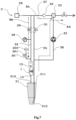
- Fig.6 shows a first operation phase of the liquid mixing system 2.
- the second valve 301 and the third valve 31 are in an open state, the second liquid, for example RO water, is transferred firstly to the bottom 212 of the canister 21 through the second flow path 25 as shown in a first arrow A1 and rises in the canister 21 while dissolving the substance, for example bicarbonate, within the canister 21.
- the second liquid rises gradually within the canister 21
- air contained in the canister 21 is expelled toward the top 211 of the canister 21 and then into the chamber 11 of the pressure vessel 1 as shown in a second arrow A2.
- the air is exhausted via the second valve 301 and the air outlet 302.
- the air detection means 15 of the pressure vessel 1 detects the second liquid without any air
- the second valve 301 and the third valve 31 are closed and then the first valve 29 is opened to transfer the first liquid, also for example RO water, into the chamber 11 of the pressure vessel 1 as shown in a third arrow A3, until the pressure detected by the pressure detection means 28 reaches the upper limit, for example 130 mbar, of the predetermined range.
- the concentrate pump 32 draws the saturated liquid concentrate from the bottom 212 of the canister 21 as shown in a fourth arrow A4 to the mixing chamber 22 to mix with the third liquid, also for example OS water, transferred into the mixing chamber 22 through the fourth flow path 27 as shown in a fifth arrow A5.
- the same amount of the first liquid is dispensed from the pressure vessel 1 to fill the canister 21 from the top inlet port 213 of the canister 21 as shown in a sixth dashed line arrow A6.
- the pressure within the first flow path 23 is monitored by the pressure detection means 28.
- the first valve 29 is opened to refill the chamber 11 of the pressure vessel 1 with the first liquid until the pressure within the first flow path 23 reaches the upper limit, for example 130 mbar, of the predetermined range.
- the above processes repeat to deliver the desired solution downstream from the mixing chamber 22.
- the concentrate pump 32 can operate at a relatively stable pressure, which is very advantageous.
- control system configured to control the liquid mixing system 2 to execute the method described above.
- a computer readable program carrier storing program instructions therein, wherein the method described above is achieved when the program instructions are executed by a processor.
Landscapes
- Health & Medical Sciences (AREA)
- Urology & Nephrology (AREA)
- Heart & Thoracic Surgery (AREA)
- Engineering & Computer Science (AREA)
- Hematology (AREA)
- Vascular Medicine (AREA)
- Anesthesiology (AREA)
- Biomedical Technology (AREA)
- Emergency Medicine (AREA)
- Life Sciences & Earth Sciences (AREA)
- Animal Behavior & Ethology (AREA)
- General Health & Medical Sciences (AREA)
- Public Health (AREA)
- Veterinary Medicine (AREA)
- General Engineering & Computer Science (AREA)
- Mechanical Engineering (AREA)
- Accessories For Mixers (AREA)
Claims (15)
- Ein Druckbehälter (1) zum Mischen von Flüssigkeiten, umfassend:ein Gehäuse (16);ein verformbares Element (111), das so konfiguriert ist, dass es zusammen mit mindestens einem Teil des Gehäuses (16) eine Kammer (11) definiert;einen Einlass (12), der in Fluidkommunikation mit der Kammer (11) steht;einen Auslass (13), der in Fluidkommunikation mit der Kammer (11) steht;ein elastisches Vorspannelement (14), das so konfiguriert ist, dass es mit dem verformbaren Element (111) interagiert, um ein Volumen der Kammer (11) variabel zu machen; undein Luftdetektionsmittel (15), das so konfiguriert ist, dass es das Vorhandensein von Luft innerhalb der Kammer (11) erkennt.
- Der Druckbehälter (1) nach Anspruch 1, wobeidas verformbare Element (111) durch eine flexible Membran gebildet ist; und/oderder Einlass (12) und der Auslass (13) einander gegenüberliegend angeordnet sind.
- Der Druckbehälter (1) nach Anspruch 1 oder 2, wobeidas elastische Vorspannelement (14) eine Feder (141), vorzugsweise eine konische Schraubenfeder, umfasst oder in Form eines komprimierten Gases, vorzugsweise komprimierter Luft, konfiguriert ist; und/oderdas Luftdetektionsmittel (15) ein Paar Luftdetektionselektroden (151) umfasst, die sich in die Kammer (11) erstrecken.
- Der Druckbehälter (1) nach einem der Ansprüche 1 bis 3, wobeiein Innenraum der Kammer (11) so konfiguriert ist, dass er einen Fluidstrom erzeugt, um die Hygienekontrolle in einem Reinigungs- und/oder Desinfektionsprozess zu erleichtern; und/oderdas elastische Vorspannelement (14) einstellbar ist, um das Volumen der Kammer (11) im Betrieb zu regeln.
- Der Druckbehälter (1) nach Anspruch 4, wobeider Innenraum der Kammer (11) in einem anfänglichen Stadium durch eine Kraft des elastischen Vorspannelements (14) bis zu einem gewissen Grad komprimiert wird;vorzugsweise der Innenraum der Kammer (11) so konfiguriert ist, dass er anfangs einen U-förmigen Querschnitt entlang einer Richtung des auf das verformbare Element (111) wirkenden elastischen Vorspannelements (14) hat und den Einlass (12) und den Auslass (13) verlängert, wobei ein Bodenabschnitt (112) des U-förmigen Querschnitts durch das verformbare Element (111) definiert ist.
- Der Druckbehälter (1) nach Anspruch 5, wobeidas Luftdetektionsmittel (15) benachbart zu einem äußeren Ende (1131) eines ersten Schenkels (113) des U-förmigen Querschnitts angeordnet ist; und/oderder Einlass (12) benachbart zu einer Ecke (114) zwischen dem ersten Schenkel (113) und dem Bodenabschnitt (112) des U-förmigen Querschnitts angeordnet ist; und/oderder Auslass (13) benachbart zu einem Mittelpunkt eines zweiten Schenkels (115) des U-förmigen Querschnitts gegenüber des ersten Schenkels (113) angeordnet ist.
- Ein Flüssigkeitsmischsystem (2), das den Druckbehälter (1) nach einem der Ansprüche 1 bis 6 umfasst.
- Das Flüssigkeitsmischsystem (2) nach Anspruch 7, wobei das Flüssigkeitsmischsystem (2) ferner umfasst:einen Kanister (21), insbesondere einen starren Kanister, zur Aufnahme einer Substanz, die von einer ersten Flüssigkeit gelöst oder verdünnt werden soll, um eine Lösung zuzubereiten, vorzugsweise eine gesättigte Lösung, wobei der Auslass (13) des Druckbehälters (1) in Fluidkommunikation mit dem Kanister (21) steht; undeine Mischkammer (22), die in Fluidkommunikation mit dem Kanister (21) steht, um die Lösung aufzunehmen;vorzugsweise ist der Einlass (12) des Druckbehälters (1) in einem Betriebszustand höher positioniert als der Auslass (13) des Druckbehälters (1).
- Das Flüssigkeitsmischsystem (2) nach Anspruch 8, wobei das Flüssigkeitsmischsystem (2) ferner umfasst:einen ersten Flussweg (23), der in Fluidkommunikation mit dem Einlass (12) des Druckbehälters (1) steht, um das Befüllen des Kanisters (21) mit der ersten Flüssigkeit über den ersten Flussweg (23) und den Druckbehälter (1) zu ermöglichen; und/odereinen zweiten Flussweg (25), der in Fluidkommunikation mit dem Kanister (21) steht, um das Befüllen des Kanisters (21) mit einer zweiten Flüssigkeit zu ermöglichen; und/odereinen dritten Flussweg (26), der in Fluidkommunikation mit dem Kanister (21) steht, um die Übertragung der Lösung in die Mischkammer (22) zu ermöglichen; und/odereinen vierten Flussweg (27), der in Fluidkommunikation mit der Mischkammer (22) steht, um eine dritte Flüssigkeit der Mischkammer (22) zuzuführen.
- Das Flüssigkeitsmischsystem (2) nach Anspruch 9, wobei das Flüssigkeitsmischsystem (2) ferner umfasst:ein Druckerfassungsmittel (28), das so konfiguriert ist, dass es einen Druck innerhalb des ersten Flusswegs (23) erfasst;ein erstes Ventil (29), das im ersten Flussweg (23) stromaufwärts des Druckerfassungsmittels (28) angeordnet ist; undein Luftauslassmittel (30), das in Fluidkommunikation mit dem ersten Flussweg (23) zwischen dem ersten Ventil (29) und dem Druckbehälter (1) steht.
- Das Flüssigkeitsmischsystem (2) nach Anspruch 10, wobeidas Luftauslassmittel (30) ein zweites Ventil (301) und einen Luftauslass (302) umfasst; und/oderder Kanister (21) in dem Betriebszustand eine Oberseite (211) und eine Unterseite (212) aufweist, und der Druckbehälter (1) in Fluidkommunikation mit einer oberen Einlassöffnung (213) des Kanisters (21) steht, um das Befüllen des Kanisters (21) mit der ersten Flüssigkeit über die Oberseite (211) des Kanisters (21) zu ermöglichen.
- Das Flüssigkeitsmischsystem (2) nach einem der Ansprüche 9 bis 11, wobeidas Flüssigkeitsmischsystem (2) ferner ein drittes Ventil (31) umfasst, das im zweiten Flussweg (25) angeordnet ist; und/oderder zweite Flussweg (25) so konfiguriert ist, dass er das Befüllen des Kanisters (21) mit der zweiten Flüssigkeit über die Unterseite (212) des Kanisters (21) ermöglicht.
- Das Flüssigkeitsmischsystem (2) nach einem der Ansprüche 9 bis 12, wobei das Flüssigkeitsmischsystem (2) ferner umfasst:eine Lösungspumpe (32), die im dritten Flussweg (26) angeordnet ist, um die Lösung in die Mischkammer (22) zu pumpen; und/oderein viertes Ventil (33), vorzugsweise ein Rückschlagventil, das im vierten Flussweg (27) angeordnet ist.
- Das Flüssigkeitsmischsystem (2) nach einem der Ansprüche 9 bis 13, wobeimindestens zwei von dem ersten Flussweg (23), dem zweiten Flussweg (25) und dem vierten Flussweg (27) in Fluidkommunikation mit einer gemeinsamen Flüssigkeitsquelle (24) stehen; und/odermindestens eine der ersten Flüssigkeit, der zweiten Flüssigkeit und der dritten Flüssigkeit Umkehrosmosewasser ist; und/oderdie Substanz in Form von Pulver, Granulat, Tabletten oder Mischungen davon vorliegt; und/oderdie Substanz Natriumchlorid und/oder Bikarbonat, insbesondere Natriumbikarbonat, umfasst.
- Ein Verfahren zur Herstellung einer Lösung unter Verwendung des Druckbehälters (1) nach einem der Ansprüche 1 bis 6 oder des Flüssigkeitsmischsystems (2) nach einem der Ansprüche 7 bis 14, umfassend:Erkennen des Vorhandenseins von Luft innerhalb der Kammer (11) des Druckbehälters (1);Ablassen der Luft durch den Druckbehälter (1) oder aus dem Flüssigkeitsmischsystem (2) im Falle des Vorhandenseins von Luft; undDurchführen der Flüssigkeitszufuhr durch den Druckbehälter (1), um die Lösung zu erhalten.
Applications Claiming Priority (1)
| Application Number | Priority Date | Filing Date | Title |
|---|---|---|---|
| PCT/CN2019/128343 WO2021128067A1 (en) | 2019-12-25 | 2019-12-25 | Pressure vessel, liquid mixing equipment, liquid mixing system, method for preparing solution, control system and computer readable program carrier |
Publications (3)
| Publication Number | Publication Date |
|---|---|
| EP4081277A1 EP4081277A1 (de) | 2022-11-02 |
| EP4081277A4 EP4081277A4 (de) | 2023-09-13 |
| EP4081277B1 true EP4081277B1 (de) | 2024-10-30 |
Family
ID=76575029
Family Applications (1)
| Application Number | Title | Priority Date | Filing Date |
|---|---|---|---|
| EP19957853.5A Active EP4081277B1 (de) | 2019-12-25 | 2019-12-25 | Druckbehälter, flüssigkeitsmischvorrichtung, flüssigkeitsmischsystem, verfahren zur herstellung einer lösung, steuerungssystem und computerlesbarer programmträger |
Country Status (4)
| Country | Link |
|---|---|
| US (1) | US20230042212A1 (de) |
| EP (1) | EP4081277B1 (de) |
| CN (1) | CN114901322A (de) |
| WO (1) | WO2021128067A1 (de) |
Families Citing this family (1)
| Publication number | Priority date | Publication date | Assignee | Title |
|---|---|---|---|---|
| WO2025020121A1 (en) * | 2023-07-26 | 2025-01-30 | Henkel Ag & Co. Kgaa | Mixer for fluid components |
Family Cites Families (22)
| Publication number | Priority date | Publication date | Assignee | Title |
|---|---|---|---|---|
| FR1547406A (fr) * | 1967-05-03 | 1968-11-29 | Cibie Projecteurs | Dispositif de compensation et de commande pour circuits hydrauliques |
| US3827561A (en) * | 1972-09-20 | 1974-08-06 | Milton Roy Co | Deaerator for dialysis system |
| US4163461A (en) * | 1978-01-23 | 1979-08-07 | Greer Hydraulics, Inc. | High frequency pulse dampener |
| US4391600A (en) * | 1979-03-09 | 1983-07-05 | Avi, Inc. | Nonpulsating IV pump and disposable pump chamber |
| US4236880A (en) * | 1979-03-09 | 1980-12-02 | Archibald Development Labs, Inc. | Nonpulsating IV pump and disposable pump chamber |
| US4227420A (en) * | 1979-06-11 | 1980-10-14 | Baxter Travenol Laboratories, Inc. | Pressure coupling mechanism in a pressure monitoring assembly |
| US4398542A (en) * | 1980-12-15 | 1983-08-16 | Ivac Corporation | Pressure diaphragm |
| DE19620591B4 (de) * | 1996-05-22 | 2004-08-26 | Fresenius Medical Care Deutschland Gmbh | Vorrichtung zum Entfernen von Gasen aus Flüssigkeiten |
| SE9704687L (sv) * | 1997-12-16 | 1999-05-31 | Gambro Lundia Ab | System och förfarande för övervakning av en doseringspump i en dialysmaskin |
| US6773670B2 (en) * | 2001-02-09 | 2004-08-10 | Cardiovention, Inc. C/O The Brenner Group, Inc. | Blood filter having a sensor for active gas removal and methods of use |
| DE10215818A1 (de) * | 2002-04-10 | 2003-10-30 | Endress & Hauser Wetzer Gmbh | Vorrichtung zur Erkennung eines vorgegebenen Füllstands eines Mediums in einem Behälter |
| JP6537298B2 (ja) * | 2014-04-30 | 2019-07-03 | キヤノン株式会社 | 圧力調整ユニット、液体供給装置、および液体吐出装置 |
| US10478544B2 (en) * | 2014-09-25 | 2019-11-19 | Nxstage Medical, Inc. | Medicament preparation and treatment devices, methods, and systems |
| CA2957067C (en) * | 2014-09-26 | 2019-02-19 | Fresenius Medical Care Holdings, Inc. | Pressure output device for extracorporeal hemodialysis machine |
| DE112016000511T5 (de) * | 2015-02-26 | 2017-11-30 | Eaton Corporation | Pulsdämpfer |
| DE202015102734U1 (de) * | 2015-05-27 | 2015-08-07 | Christoph Dumschat | Dialysekonzentrat-Herstellungsanordnung |
| US9945838B2 (en) * | 2015-12-17 | 2018-04-17 | Fresenius Medical Care Holdings, Inc. | Extracorporeal circuit blood chamber having an integrated deaeration device |
| WO2019119414A1 (en) * | 2017-12-22 | 2019-06-27 | Fresenius Medical Care Deutschland Gmbh | Backflow Prevention Device and Dialysis Apparatus with the Backflow Prevention Device |
| CN108121093B (zh) * | 2017-12-29 | 2020-08-04 | 深圳市华星光电技术有限公司 | 调压装置和喷涂刀具 |
| DE102018003644A1 (de) * | 2018-05-04 | 2019-11-07 | Hydac Technology Gmbh | Dämpfungsvorrichtung |
| CN118403244A (zh) * | 2018-10-19 | 2024-07-30 | 斯泰米德有限公司 | 提供医疗溶液的装置和系统及其方法 |
| CN109550095A (zh) * | 2018-11-23 | 2019-04-02 | 台州黄岩羽山综合门诊部 | 一种肾脏内科用血液透析液配制设备 |
-
2019
- 2019-12-25 EP EP19957853.5A patent/EP4081277B1/de active Active
- 2019-12-25 US US17/788,882 patent/US20230042212A1/en not_active Abandoned
- 2019-12-25 CN CN201980103329.1A patent/CN114901322A/zh active Pending
- 2019-12-25 WO PCT/CN2019/128343 patent/WO2021128067A1/en not_active Ceased
Also Published As
| Publication number | Publication date |
|---|---|
| EP4081277A4 (de) | 2023-09-13 |
| CN114901322A (zh) | 2022-08-12 |
| EP4081277A1 (de) | 2022-11-02 |
| WO2021128067A1 (en) | 2021-07-01 |
| US20230042212A1 (en) | 2023-02-09 |
Similar Documents
| Publication | Publication Date | Title |
|---|---|---|
| US11020517B2 (en) | Treatment solution delivery in an extracorporeal blood treatment apparatus | |
| US10357600B2 (en) | Extracorporeal blood treatment system, disposable set and valve unit for pre/post infusion | |
| JP6205649B2 (ja) | 透析装置 | |
| CA2681916C (en) | Cassette system integrated apparatus | |
| EP2155287B1 (de) | Druckerfassungsvorrichtung und deren verwendung in einer verbindungsstruktur | |
| EP3305344A1 (de) | Medizinischer flüssigkeitsdruckdetektor | |
| JP4658190B2 (ja) | 医療用流体給送装置及び方法 | |
| CN101444648B (zh) | 用于血液透析机中的负压除气装置 | |
| CN106488882A (zh) | 用于填充容器的方法 | |
| CN106061524B (zh) | 用于在从医学的处理装置中的流出和流入之间进行平衡的装置和方法 | |
| KR101638251B1 (ko) | 혈액투석 장치 | |
| WO2021128067A1 (en) | Pressure vessel, liquid mixing equipment, liquid mixing system, method for preparing solution, control system and computer readable program carrier | |
| JP2018533993A (ja) | 透析液中の物質を検出するための感知システム | |
| JP7183006B2 (ja) | 体液分離システム及び体液分離システムの作動方法 | |
| US11246969B2 (en) | Apparatus for extracorporeal blood treatment and method for operating an extracorporeal blood treatment apparatus | |
| EP3991764B1 (de) | Durchflussmesser zum dosieren von wasser in einem dialysesystem | |
| CN121443334A (zh) | 生成用于肾脏替代治疗的医疗流体 | |
| CN108474366B (zh) | 包括具有隔膜泵和阀的配给管路的血液治疗仪和用于配给的方法 | |
| JP3187938B2 (ja) | 血液透析装置 | |
| JP2022063108A (ja) | 体腔液処理システム | |
| JP3198495B2 (ja) | 透析液調製装置 | |
| CN111936178B (zh) | 透析设备 | |
| AU2018250446A1 (en) | Dialysis system of integrated manifolds | |
| CN104203305B (zh) | 体外血液治疗设备中的治疗溶液输送 | |
| JP5814657B2 (ja) | 薬液注入ユニット、及び薬液注入ユニットの制御方法 |
Legal Events
| Date | Code | Title | Description |
|---|---|---|---|
| STAA | Information on the status of an ep patent application or granted ep patent |
Free format text: STATUS: THE INTERNATIONAL PUBLICATION HAS BEEN MADE |
|
| PUAI | Public reference made under article 153(3) epc to a published international application that has entered the european phase |
Free format text: ORIGINAL CODE: 0009012 |
|
| STAA | Information on the status of an ep patent application or granted ep patent |
Free format text: STATUS: REQUEST FOR EXAMINATION WAS MADE |
|
| 17P | Request for examination filed |
Effective date: 20220725 |
|
| AK | Designated contracting states |
Kind code of ref document: A1 Designated state(s): AL AT BE BG CH CY CZ DE DK EE ES FI FR GB GR HR HU IE IS IT LI LT LU LV MC MK MT NL NO PL PT RO RS SE SI SK SM TR |
|
| DAV | Request for validation of the european patent (deleted) | ||
| DAX | Request for extension of the european patent (deleted) | ||
| A4 | Supplementary search report drawn up and despatched |
Effective date: 20230810 |
|
| RIC1 | Information provided on ipc code assigned before grant |
Ipc: F15B 1/04 20060101ALI20230807BHEP Ipc: F15B 1/02 20060101ALI20230807BHEP Ipc: A61M 1/16 20060101ALI20230807BHEP Ipc: A61M 1/28 20060101ALI20230807BHEP Ipc: A61M 1/14 20060101AFI20230807BHEP |
|
| GRAP | Despatch of communication of intention to grant a patent |
Free format text: ORIGINAL CODE: EPIDOSNIGR1 |
|
| STAA | Information on the status of an ep patent application or granted ep patent |
Free format text: STATUS: GRANT OF PATENT IS INTENDED |
|
| INTG | Intention to grant announced |
Effective date: 20240523 |
|
| GRAS | Grant fee paid |
Free format text: ORIGINAL CODE: EPIDOSNIGR3 |
|
| GRAA | (expected) grant |
Free format text: ORIGINAL CODE: 0009210 |
|
| STAA | Information on the status of an ep patent application or granted ep patent |
Free format text: STATUS: THE PATENT HAS BEEN GRANTED |
|
| AK | Designated contracting states |
Kind code of ref document: B1 Designated state(s): AL AT BE BG CH CY CZ DE DK EE ES FI FR GB GR HR HU IE IS IT LI LT LU LV MC MK MT NL NO PL PT RO RS SE SI SK SM TR |
|
| REG | Reference to a national code |
Ref country code: GB Ref legal event code: FG4D |
|
| REG | Reference to a national code |
Ref country code: CH Ref legal event code: EP |
|
| P01 | Opt-out of the competence of the unified patent court (upc) registered |
Free format text: CASE NUMBER: APP_55346/2024 Effective date: 20241009 |
|
| REG | Reference to a national code |
Ref country code: DE Ref legal event code: R096 Ref document number: 602019061354 Country of ref document: DE |
|
| REG | Reference to a national code |
Ref country code: IE Ref legal event code: FG4D |
|
| PGFP | Annual fee paid to national office [announced via postgrant information from national office to epo] |
Ref country code: DE Payment date: 20241121 Year of fee payment: 6 |
|
| PGFP | Annual fee paid to national office [announced via postgrant information from national office to epo] |
Ref country code: FR Payment date: 20241121 Year of fee payment: 6 |
|
| REG | Reference to a national code |
Ref country code: LT Ref legal event code: MG9D |
|
| REG | Reference to a national code |
Ref country code: NL Ref legal event code: MP Effective date: 20241030 |
|
| PG25 | Lapsed in a contracting state [announced via postgrant information from national office to epo] |
Ref country code: IS Free format text: LAPSE BECAUSE OF FAILURE TO SUBMIT A TRANSLATION OF THE DESCRIPTION OR TO PAY THE FEE WITHIN THE PRESCRIBED TIME-LIMIT Effective date: 20250228 Ref country code: HR Free format text: LAPSE BECAUSE OF FAILURE TO SUBMIT A TRANSLATION OF THE DESCRIPTION OR TO PAY THE FEE WITHIN THE PRESCRIBED TIME-LIMIT Effective date: 20241030 Ref country code: PT Free format text: LAPSE BECAUSE OF FAILURE TO SUBMIT A TRANSLATION OF THE DESCRIPTION OR TO PAY THE FEE WITHIN THE PRESCRIBED TIME-LIMIT Effective date: 20250228 |
|
| PG25 | Lapsed in a contracting state [announced via postgrant information from national office to epo] |
Ref country code: NL Free format text: LAPSE BECAUSE OF FAILURE TO SUBMIT A TRANSLATION OF THE DESCRIPTION OR TO PAY THE FEE WITHIN THE PRESCRIBED TIME-LIMIT Effective date: 20241030 Ref country code: FI Free format text: LAPSE BECAUSE OF FAILURE TO SUBMIT A TRANSLATION OF THE DESCRIPTION OR TO PAY THE FEE WITHIN THE PRESCRIBED TIME-LIMIT Effective date: 20241030 |
|
| REG | Reference to a national code |
Ref country code: AT Ref legal event code: MK05 Ref document number: 1736292 Country of ref document: AT Kind code of ref document: T Effective date: 20241030 |
|
| PG25 | Lapsed in a contracting state [announced via postgrant information from national office to epo] |
Ref country code: BG Free format text: LAPSE BECAUSE OF FAILURE TO SUBMIT A TRANSLATION OF THE DESCRIPTION OR TO PAY THE FEE WITHIN THE PRESCRIBED TIME-LIMIT Effective date: 20241030 |
|
| PG25 | Lapsed in a contracting state [announced via postgrant information from national office to epo] |
Ref country code: ES Free format text: LAPSE BECAUSE OF FAILURE TO SUBMIT A TRANSLATION OF THE DESCRIPTION OR TO PAY THE FEE WITHIN THE PRESCRIBED TIME-LIMIT Effective date: 20241030 |
|
| PG25 | Lapsed in a contracting state [announced via postgrant information from national office to epo] |
Ref country code: NO Free format text: LAPSE BECAUSE OF FAILURE TO SUBMIT A TRANSLATION OF THE DESCRIPTION OR TO PAY THE FEE WITHIN THE PRESCRIBED TIME-LIMIT Effective date: 20250130 |
|
| PG25 | Lapsed in a contracting state [announced via postgrant information from national office to epo] |
Ref country code: LV Free format text: LAPSE BECAUSE OF FAILURE TO SUBMIT A TRANSLATION OF THE DESCRIPTION OR TO PAY THE FEE WITHIN THE PRESCRIBED TIME-LIMIT Effective date: 20241030 Ref country code: AT Free format text: LAPSE BECAUSE OF FAILURE TO SUBMIT A TRANSLATION OF THE DESCRIPTION OR TO PAY THE FEE WITHIN THE PRESCRIBED TIME-LIMIT Effective date: 20241030 Ref country code: GR Free format text: LAPSE BECAUSE OF FAILURE TO SUBMIT A TRANSLATION OF THE DESCRIPTION OR TO PAY THE FEE WITHIN THE PRESCRIBED TIME-LIMIT Effective date: 20250131 |
|
| PG25 | Lapsed in a contracting state [announced via postgrant information from national office to epo] |
Ref country code: PL Free format text: LAPSE BECAUSE OF FAILURE TO SUBMIT A TRANSLATION OF THE DESCRIPTION OR TO PAY THE FEE WITHIN THE PRESCRIBED TIME-LIMIT Effective date: 20241030 |
|
| PG25 | Lapsed in a contracting state [announced via postgrant information from national office to epo] |
Ref country code: RS Free format text: LAPSE BECAUSE OF FAILURE TO SUBMIT A TRANSLATION OF THE DESCRIPTION OR TO PAY THE FEE WITHIN THE PRESCRIBED TIME-LIMIT Effective date: 20250130 |
|
| PG25 | Lapsed in a contracting state [announced via postgrant information from national office to epo] |
Ref country code: SM Free format text: LAPSE BECAUSE OF FAILURE TO SUBMIT A TRANSLATION OF THE DESCRIPTION OR TO PAY THE FEE WITHIN THE PRESCRIBED TIME-LIMIT Effective date: 20241030 |
|
| PG25 | Lapsed in a contracting state [announced via postgrant information from national office to epo] |
Ref country code: MC Free format text: LAPSE BECAUSE OF FAILURE TO SUBMIT A TRANSLATION OF THE DESCRIPTION OR TO PAY THE FEE WITHIN THE PRESCRIBED TIME-LIMIT Effective date: 20241030 |
|
| PG25 | Lapsed in a contracting state [announced via postgrant information from national office to epo] |
Ref country code: DK Free format text: LAPSE BECAUSE OF FAILURE TO SUBMIT A TRANSLATION OF THE DESCRIPTION OR TO PAY THE FEE WITHIN THE PRESCRIBED TIME-LIMIT Effective date: 20241030 |
|
| PG25 | Lapsed in a contracting state [announced via postgrant information from national office to epo] |
Ref country code: EE Free format text: LAPSE BECAUSE OF FAILURE TO SUBMIT A TRANSLATION OF THE DESCRIPTION OR TO PAY THE FEE WITHIN THE PRESCRIBED TIME-LIMIT Effective date: 20241030 |
|
| PG25 | Lapsed in a contracting state [announced via postgrant information from national office to epo] |
Ref country code: RO Free format text: LAPSE BECAUSE OF FAILURE TO SUBMIT A TRANSLATION OF THE DESCRIPTION OR TO PAY THE FEE WITHIN THE PRESCRIBED TIME-LIMIT Effective date: 20241030 |
|
| PG25 | Lapsed in a contracting state [announced via postgrant information from national office to epo] |
Ref country code: SK Free format text: LAPSE BECAUSE OF FAILURE TO SUBMIT A TRANSLATION OF THE DESCRIPTION OR TO PAY THE FEE WITHIN THE PRESCRIBED TIME-LIMIT Effective date: 20241030 |
|
| PG25 | Lapsed in a contracting state [announced via postgrant information from national office to epo] |
Ref country code: CZ Free format text: LAPSE BECAUSE OF FAILURE TO SUBMIT A TRANSLATION OF THE DESCRIPTION OR TO PAY THE FEE WITHIN THE PRESCRIBED TIME-LIMIT Effective date: 20241030 |
|
| PG25 | Lapsed in a contracting state [announced via postgrant information from national office to epo] |
Ref country code: IT Free format text: LAPSE BECAUSE OF FAILURE TO SUBMIT A TRANSLATION OF THE DESCRIPTION OR TO PAY THE FEE WITHIN THE PRESCRIBED TIME-LIMIT Effective date: 20241030 |
|
| REG | Reference to a national code |
Ref country code: CH Ref legal event code: PL Ref country code: DE Ref legal event code: R097 Ref document number: 602019061354 Country of ref document: DE |
|
| PG25 | Lapsed in a contracting state [announced via postgrant information from national office to epo] |
Ref country code: LU Free format text: LAPSE BECAUSE OF NON-PAYMENT OF DUE FEES Effective date: 20241225 |
|
| PLBE | No opposition filed within time limit |
Free format text: ORIGINAL CODE: 0009261 |
|
| STAA | Information on the status of an ep patent application or granted ep patent |
Free format text: STATUS: NO OPPOSITION FILED WITHIN TIME LIMIT |
|
| PG25 | Lapsed in a contracting state [announced via postgrant information from national office to epo] |
Ref country code: SE Free format text: LAPSE BECAUSE OF FAILURE TO SUBMIT A TRANSLATION OF THE DESCRIPTION OR TO PAY THE FEE WITHIN THE PRESCRIBED TIME-LIMIT Effective date: 20241030 |
|
| GBPC | Gb: european patent ceased through non-payment of renewal fee |
Effective date: 20250130 |
|
| 26N | No opposition filed |
Effective date: 20250731 |
|
| REG | Reference to a national code |
Ref country code: BE Ref legal event code: MM Effective date: 20241231 |
|
| PG25 | Lapsed in a contracting state [announced via postgrant information from national office to epo] |
Ref country code: GB Free format text: LAPSE BECAUSE OF NON-PAYMENT OF DUE FEES Effective date: 20250130 Ref country code: BE Free format text: LAPSE BECAUSE OF NON-PAYMENT OF DUE FEES Effective date: 20241231 |
|
| PG25 | Lapsed in a contracting state [announced via postgrant information from national office to epo] |
Ref country code: CH Free format text: LAPSE BECAUSE OF NON-PAYMENT OF DUE FEES Effective date: 20241231 |
|
| PG25 | Lapsed in a contracting state [announced via postgrant information from national office to epo] |
Ref country code: IE Free format text: LAPSE BECAUSE OF NON-PAYMENT OF DUE FEES Effective date: 20241225 |