EP4081486B1 - Dessableur circulaire à plaques parallèles - Google Patents
Dessableur circulaire à plaques parallèles Download PDFInfo
- Publication number
- EP4081486B1 EP4081486B1 EP21806618.1A EP21806618A EP4081486B1 EP 4081486 B1 EP4081486 B1 EP 4081486B1 EP 21806618 A EP21806618 A EP 21806618A EP 4081486 B1 EP4081486 B1 EP 4081486B1
- Authority
- EP
- European Patent Office
- Prior art keywords
- grit
- grit removal
- removal chamber
- chamber
- plates
- Prior art date
- Legal status (The legal status is an assumption and is not a legal conclusion. Google has not performed a legal analysis and makes no representation as to the accuracy of the status listed.)
- Active
Links
Images





Classifications
-
- E—FIXED CONSTRUCTIONS
- E03—WATER SUPPLY; SEWERAGE
- E03F—SEWERS; CESSPOOLS
- E03F5/00—Sewerage structures
- E03F5/14—Devices for separating liquid or solid substances from sewage, e.g. sand or sludge traps, rakes or grates
-
- B—PERFORMING OPERATIONS; TRANSPORTING
- B01—PHYSICAL OR CHEMICAL PROCESSES OR APPARATUS IN GENERAL
- B01D—SEPARATION
- B01D21/00—Separation of suspended solid particles from liquids by sedimentation
- B01D21/0003—Making of sedimentation devices, structural details thereof, e.g. prefabricated parts
-
- B—PERFORMING OPERATIONS; TRANSPORTING
- B01—PHYSICAL OR CHEMICAL PROCESSES OR APPARATUS IN GENERAL
- B01D—SEPARATION
- B01D21/00—Separation of suspended solid particles from liquids by sedimentation
- B01D21/0039—Settling tanks provided with contact surfaces, e.g. baffles, particles
- B01D21/0042—Baffles or guide plates
-
- B—PERFORMING OPERATIONS; TRANSPORTING
- B01—PHYSICAL OR CHEMICAL PROCESSES OR APPARATUS IN GENERAL
- B01D—SEPARATION
- B01D21/00—Separation of suspended solid particles from liquids by sedimentation
- B01D21/0039—Settling tanks provided with contact surfaces, e.g. baffles, particles
- B01D21/0045—Plurality of essentially parallel plates
-
- B—PERFORMING OPERATIONS; TRANSPORTING
- B01—PHYSICAL OR CHEMICAL PROCESSES OR APPARATUS IN GENERAL
- B01D—SEPARATION
- B01D21/00—Separation of suspended solid particles from liquids by sedimentation
- B01D21/0087—Settling tanks provided with means for ensuring a special flow pattern, e.g. even inflow or outflow
-
- B—PERFORMING OPERATIONS; TRANSPORTING
- B01—PHYSICAL OR CHEMICAL PROCESSES OR APPARATUS IN GENERAL
- B01D—SEPARATION
- B01D21/00—Separation of suspended solid particles from liquids by sedimentation
- B01D21/24—Feed or discharge mechanisms for settling tanks
- B01D21/2405—Feed mechanisms for settling tanks
- B01D21/2411—Feed mechanisms for settling tanks having a tangential inlet
-
- B—PERFORMING OPERATIONS; TRANSPORTING
- B01—PHYSICAL OR CHEMICAL PROCESSES OR APPARATUS IN GENERAL
- B01D—SEPARATION
- B01D21/00—Separation of suspended solid particles from liquids by sedimentation
- B01D21/24—Feed or discharge mechanisms for settling tanks
- B01D21/2433—Discharge mechanisms for floating particles
- B01D21/2438—Discharge mechanisms for floating particles provided with scrapers on the liquid surface for removing floating particles
-
- B—PERFORMING OPERATIONS; TRANSPORTING
- B01—PHYSICAL OR CHEMICAL PROCESSES OR APPARATUS IN GENERAL
- B01D—SEPARATION
- B01D21/00—Separation of suspended solid particles from liquids by sedimentation
- B01D21/24—Feed or discharge mechanisms for settling tanks
- B01D21/245—Discharge mechanisms for the sediments
- B01D21/2472—Means for fluidising the sediments, e.g. by jets or mechanical agitators
-
- B—PERFORMING OPERATIONS; TRANSPORTING
- B01—PHYSICAL OR CHEMICAL PROCESSES OR APPARATUS IN GENERAL
- B01D—SEPARATION
- B01D21/00—Separation of suspended solid particles from liquids by sedimentation
- B01D21/26—Separation of sediment aided by centrifugal force or centripetal force
- B01D21/265—Separation of sediment aided by centrifugal force or centripetal force by using a vortex inducer or vortex guide, e.g. coil
Definitions
- the present invention relates to a grit remover, collector and/or trap for selectively removing sand and grit from a flowing stream of fluid.
- Grit is one of the most unpredictable and difficult materials a sewage treatment plant must handle.
- Grit can be defined as the heavy mineral matter present in sewage. It is principally made up of sand, gravel, and inorganic material with a specific gravity of 2.65 which reaches a sewage disposal plant. It is desirous to remove this material as it cannot be treated, reduced in size, or eliminated by treatment methods. It presents a problem to waste treatment as it is hard and abrasive. It wears pumps and other mechanical devices. It is heavy and accumulates in clarifiers, treatment basins, digesters, etc., where it must sometimes be removed manually.
- Grit removal devices of various designs have been proposed to remove grit from a flowing stream of water.
- inclined flat plate separators known as lamella units have been used in various types of equipment for separating solids from liquid and in other separation applications. See, e.g., U.S. Patent Nos. 6,921,489 and 6,960,304 .
- U.S. Pat. No. 3,941,698 includes an upper settling chamber and a lower grit storage chamber.
- the settling chamber being of large diameter, communicates with the storage chamber through a relatively small opening in a substantially flat transition surface therebetween.
- Rotating paddles positioned within the settling chamber, a short distance above the transition surface can enhance the natural rotational flow of liquid entering the settling chamber adjacent the outer periphery to rotate about the chamber as a forced vortex resulting in an upward spiral flow which urges the settled particles across the transition surface towards the opening.
- the heavier settled particles fall through the opening into the storage chamber and the lighter organic particles rise in the spiral flow.
- the contents in the storage chamber are lightly air scoured prior to removal to cause any organics therein to be lifted out of the storage chamber and returned to the settling chamber.
- a similar type of grit removal device is disclosed in U.S. Pat. No. 4,107,038 , in which a ramp is in communication with the flume portion of the inlet trough to cause grit to follow the ramp down towards the transition surface.
- a baffle is also positioned in the settling chamber against which the rotating liquid impinges to deflect the liquid downwardly into a generally toroidal flow pattern that spirals around the periphery of the settling chamber. The toroidal motion of the liquid moves the grit on the transition surface towards the center opening.
- U.S. Pat. Nos. 4,767,532 and 7,971,732 also disclose vortex-type grit extractor apparatuses.
- U.S. Pat. No. 4,767,532 discloses an apparatus for removing grit in which a grit storage chamber is provided beneath the center of the round chamber of the grit removal system.
- a removable plate substantially aligned with the floor of the round chamber generally separates the two chambers, with a central opening through the plate permitting communication between the chambers.
- a cylindrical shaft is rotatably supported on its upper end above the round chamber and extends down through the round chamber through the plate central opening.
- Liquid flow in the round chamber forces grit particles to settle toward the chamber floor, where they are urged radially inwardly so as to drop through the plate central opening into the grit storage chamber.
- a multi-bladed propeller is mounted on that shaft above the plate, and rotates with the shaft to assist in the liquid flow to move the grit toward the plate center opening.
- a pipe also extends down through the cylindrical shaft into the grit storage chamber, and a pump is provided on the upper end of the pipe to allow grit in the bottom of the storage chamber to be removed by pumping up through the pipe.
- U.S. Pat. Nos. 6,811,697 , 8,906,233 and 9,932,731 flow toward the center of a chamber is facilitated by a rotating propeller or paddle.
- U.S. Pat. No. 8,906,233 also includes a ring around the interior periphery of the settling chamber blocking fluid flowing around the outside of the chamber from rising up to the level of the chamber outlet.
- EP0671197 discloses a settler for liquids to be purified comprising a tank which embodies a plurality of hollow truncated-cone shaped elements stacked coaxially with their minimum diameter facing the tank bottom and delimiting intermediate passages which extend conically from the element centre holes towards the periphery of the tank.
- an intermediate horizontal partition which divides the tank into a lower chamber, to which an inlet duct for the delivery of dirty liquid is connected, and an upper chamber, to which an outlet duct for purified liquid is connected.
- Grit removal devices as described above, whether operating by settling or vortex action, require a relatively large footprint, presenting space problems in designing overall treatment facilities in which the grit removal devices are only a part.
- larger devices are inherently more costly, and can use more energy.
- such devices are not as well adapted as might be desired to operate efficiently in environments in which the flow rate varies widely. Still further, the ability of the devices to efficiently remove grit can always be improved.
- the present invention is directed toward, inter alia, one or more of the problems set forth above.
- a grit removal unit for a wastewater system for removing grit from a fluid includes a grit removal chamber cylindrical about a center vertical axis with a grit storage chamber disposed below the grit removal chamber, and at least one opening through the bottom of the grit removal chamber. At least one layer plate which is an inverted truncated cone around the center axis is spaced from the grit removal chamber vertical wall to allow fluid flow between the at least one layer plate and the grit removal chamber vertical wall.
- a plurality of concentric inverted truncated cone lamella plates are also in the grit removal chamber around the center axis and above the at least one layer plate, the lamella plates being radially spaced from one another relative to the center axis wherein the spacings between adjacent lamella plates define flow paths through which wastewater flows upwardly.
- An influent opening in the grit removal chamber vertical wall below the layered plates allows fluid and grit into the grit removal chamber, and an effluent opening in the grit removal chamber vertical wall above the lamella plates allows fluid to exit the grit removal chamber.
- a center shaft is substantially coaxial with the center axis and rotatable around the central vertical axis, and blades projecting from and rotatable with the center shaft are disposed above the opening through the grit removal chamber bottom surface.
- the blades are configured to direct flow of the fluid up around the center shaft and assist with forcing grit toward the grit storage chamber.
- the grit removal chamber vertical wall is substantially annular about the center axis.
- an enclosed influent channel is adapted to direct wastewater into the grit removal chamber beneath the layered plates.
- the enclosed influent channel is adapted to direct wastewater into the grit removal chamber adjacent the grit removal chamber bottom surface and substantially tangential to the grit removal chamber vertical wall.
- the at least one layer plate is a substantially flatter truncated cone than the lamella plates.
- the at least one layer plate has a center opening larger than the center shaft.
- a FOG removal system is in the grit removal chamber above the lamella plates and beneath the effluent opening.
- the at least one layer plate includes a first layer plate, and second and third layer plates vertically spaced from the first layer plate.
- the second layer plate is between the first and third layer plates and is substantially adjacent the grit removal chamber vertical wall to substantially block fluid flow between the second layer plate and the grit removal chamber wall.
- the third layer plate is spaced from the grit removal chamber vertical wall to allow fluid flow between the third layer plate and the grit removal chamber vertical wall.
- a grit removal unit for removing grit from a fluid includes a grit removal chamber with a vertical wall which is annular about a central vertical axis, with a grit storage chamber disposed below the grit removal chamber, and at least one opening through the grit removal chamber bottom surface through which grit from the grit removal chamber may pass into the grit storage chamber.
- a center shaft is coaxial with, and rotatable around, the center axis. Blades project from, and rotate with, the center shaft, with the blades disposed above the grit storage chamber and configured to direct flow of fluid up around the center shaft.
- At least one layer plate is in the grit removal chamber in the shape of inverted truncated cones annular around the center axis.
- the at least one layer plate is spaced from the grit removal chamber annular vertical wall to allow fluid flow between it and the annular vertical wall.
- a plurality of concentric inverted truncated cone lamella plates are supported in the grit removal chamber around the center shaft and above the at least one layer plate.
- An influent opening in the grit removal chamber vertical wall below the layer plate allows the fluid and grit to enter the grit removal chamber through the influent opening.
- An effluent opening in the grit removal chamber vertical wall above the lamella plates allows fluid and grit to exit the grit removal chamber above the lamella plates.
- an enclosed influent channel is adapted to direct wastewater into the grit removal chamber beneath the layered plates.
- the enclosed influent channel is adapted to direct wastewater into the grit removal chamber adjacent the grit removal chamber bottom surface and substantially tangential to a grit removal chamber substantially annular vertical wall.
- an effluent channel is adapted to direct fluid from the grit removal chamber above the lamella plates.
- the at least one layer plate is a substantially flatter truncated cone than the lamella plates.
- the at least one layer plate has a center opening larger than the center shaft.
- a FOG removal system is in the grit removal chamber above the lamella plates and beneath the effluent opening.
- the layer plates there are at least three layer plates in the grit removal chamber, with the three layer plates being inverted truncated cones annular around the central vertical axis.
- the layer plates are vertically spaced from one another wherein a middle one of the three layer plates is substantially adjacent the grit removal chamber annular vertical wall to substantially block fluid flow between the middle layer plate and the annular vertical wall, and the layer plates above and below the middle layer plate are spaced from the grit removal chamber vertical wall to allow fluid flow between the grit removal chamber vertical wall and the layer plates above and below the middle layer plate.
- the grit removal unit includes an annular grit removal chamber with a bottom surface and a grit storage chamber disposed below the grit removal chamber and at least one opening through the bottom surface through which grit may pass into the grit storage chamber.
- a center shaft is rotatable around a vertical center axis and blades project from, and are rotatable with, the center shaft adjacent and above the bottom surface opening to direct flow of the fluid up around the center shaft.
- At least three layered plates which are inverted truncated cones annular around the center axis are vertically spaced from one another with a middle one of the three layered plates being substantially adjacent the grit removal chamber vertical wall to substantially block fluid flow between the middle layered plate and the annular vertical wall.
- the layered plates have center openings larger than the center shaft.
- a plurality of concentric inverted truncated cone lamella plates are in the grit removal chamber around the center shaft and above the layered plates.
- An enclosed influent channel is connected to an influent opening through the grit removal chamber annular vertical wall below the layered plates, whereby wastewater is directed into the grit removal chamber in a direction substantially tangential to the grit removal chamber vertical wall.
- An effluent channel is connected to an effluent opening in the grit removal chamber annular vertical wall above the lamella plates and allows fluid to exit.
- a FOG removal system is in the grit removal chamber above the lamella plates and beneath the effluent opening.
- the wastewater flows through the layered plates in a substantially serpentine path.
- the layered plates are substantially flatter truncated cones than the lamella plates.
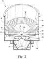
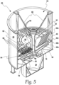
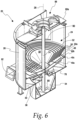
- a grit removal unit 20 is variously shown in Figs. 1-10 .
- the grit removal unit 20 includes a grit removal chamber 24 including a vertical wall 26 which is substantially annular or cylindrical about a central axis 28 and extending upwardly from a bottom surface 30.
- Beneath the bottom surface 30 is a hopper or grit storage chamber 34, where grit removed from fluid in the grit removal chamber 24 is directed and captured (collected) for periodic removal for dewatering and disposal.
- the grit removal chamber bottom surface 30 includes one or more openings 36 therethrough toward which wastewater (fluid with grit) is directed for passage down into the grit storage chamber 34.
- the layered plates 40a, 40b, 40c are in the grit removal chamber 24 spaced above the grit removal chamber bottom surface 30 (the multiple plates 40a, 40b, 40c are "layered” and referred to as such, but individual plates are also referred to herein as "layer” plates).
- the layered plates 40a-c are relatively flat inverted truncated cones - that is, they are annular around the central axis 28 with their wide end above the narrow end 42a-c, where the narrow ends 42a-c each have a central opening 44 therethrough.
- the layered plates 40a-c are vertically spaced from one another, with the middle layered plate 40b extending outwardly to the grit storage chamber vertical wall 26 where a suitable seal or gasket 46 preventing wastewater from passing between the vertical wall 26 and the middle layered plate 40b may be advantageously provided.
- the gasket 46 also helps for proper fit if any components are out of tolerance
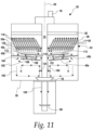
- the top and bottom layered plates 40a, 40c are, by contrast, spaced from the grit storage chamber vertical wall 26 and extend further toward the central axis 28 than the middle layered plate 40b so that, as described in greater detail hereafter in connection with Fig. 11 , wastewater will flow up from the bottom of the grit removal chamber 24 and between the layered plates 40a-c in a serpentine manner.
- a plurality of concentric inverted truncated cone lamella-style (lamella) plates 50 are disposed above the layered plates 40a-c in the grit removal chamber 24 and centered around the central axis 28.
- the outermost lamella plate 50a like the middle layered plate 40b, extends outwardly to the grit storage chamber vertical wall 28 with a suitable seal or gasket 52 preventing wastewater from passing between the vertical wall 26 and the outside of the outermost lamella plate 50a.
- gaskets 46, 52 will avoid and/or correct for field construction mistakes which can result in improper diameters and/or concentricity of the grit removal chamber 24. That is, flexible/compressible gaskets 46, 52 allow elimination of gaps around the outside of the grit removal chamber 24 through which grit particles may short cut through the unit 20 and decrease grit particle capture efficiency.
- the inclined configuration of the layered plates 40a-c and lamella plates 50a-h provide a self-cleaning mechanism which prevents excessive buildup of the solids and clogging.
- the layered plates 40a-c and lamella plates 50 may advantageously be in the shape of inverted truncated cones, with the layered plates 40a-c substantially flatter cones than the lamella plates 50.
- the plates may in some forms have flat rather than curved sides, with pyramidal flat sides approximating a truncated cone, such as a four sided pyramid or octagonal pyramid. As used herein, such shapes are to be considered to be truncated cones.
- a suitable bracket structure 60 may be secured to the grit removal chamber 24 (see Figs. 4-7 ) for supporting the described plates 40a-c, 50 and other components.
- circumferentially spaced radial supports 62, 64 are disposed at the top and bottom of the lamella plates 50 with slots 66, 68 therein receiving the top and bottom lips of the lamella plates 50 to thereby support the lamella plates 50 in concentric spaced locations.
- the bracket structure 60a may further function to support a center shaft 74 which may be rotatably driven (see drive 76 in Fig. 11 ) about the center axis 28 to drive propeller blades 78 near the bottom surface 30 of the grit removal chamber 24 to direct the flow of wastewater and hydraulically forced grit toward the grit storage chamber 34 as desired and described in further detail hereafter, and drive fluidizing vanes 80 near the bottom surface of the grit storage chamber 34 to stir settled grit.
- a top bracket 60a across the top of the grit removal chamber 24 may similarly support a suitable drive to rotate the center shaft 74 as desired.
- An enclosed influent channel 82 is connected to an influent opening through the grit removal chamber vertical wall 26 beneath the layered plates 40a-c and generally tangentially to the grit removal chamber annular vertical wall 26. Wastewater thus enters the grit removal chamber 24 at its outer perimeter where the vertical wall 26 directs the flow toward circling around the outer perimeter - that is, in a vortex movement.
- An effluent channel 88 is connected to an effluent opening 90 in the grit removal chamber vertical wall 26 above the lamella plates 50.
- the input wastewater minus the removed grit passes out of the grit removal unit 20 to allow for further processing where necessary.
- a fat, oil and grease (“FOG” as used herein) removal system 92 (see Fig. 11 ) with a skimmer arm may also be included above the lamella plates 50 and below the effluent channel 88. FOG particles flow with and float on the wastewater due to lower density.
- the FOG removal system 92 may include static and/or dynamic FOG capturing media allowing constant contact with the everchanging water height for continuous capturing of FOG particles.
- a skimmer arm may also be advantageously included to accumulate and drain a small depth of the water stream height to facilitate acquiring floating FOG particles.
- the FOG removal system 92 helps collect (capture) and remove (dispose of) any greases, oils and fats which might become nuisances in apparatuses such as may be downstream of the grit removal unit 20 which further treat the effluent from the grit removal unit 20. Thus, creation of odor emitting bacteria which can occur with coagulation and collection of FOG particles in no-flow areas of the equipment downstream from the grit removal unit 20 may be avoided.
- grit removal unit 20 Operation of the grit removal unit 20 may thus be best understood by reference to the schematic view of Fig. 11 .
- wastewater flow in the grit removal chamber 24 enters tangentially to the annular vertical wall 26 and then swirls around the bottom of the grit removal chamber 24 to create a vortex in which grit falls down toward the bottom surface 30 and is drawn to the center where such grit may fall through the openings 36 and into the grit storage chamber 34.
- the propeller blades 78 propel wastewater near the center of the grit removal chamber 24 up to also add a donut-like flow element such as shown by arrows 100. Along with the propeller blades 78 and vortex movement, such flow element also facilitates the settling or falling out of the grit particles as well as the movement of such particles toward the center where they may fall into the grit storage chamber 34.
- wastewater exiting from the channel between the middle layered plate 40b and top layered plate 40c (arrows 114) will continue to flow upwards, this time through the spaces between the lamella plates 50 (arrows 116).
- grit particles still remaining in the wastewater passing through the lamella plates 50 will settle out due to the large effective settling area of the lamella plates 50, which settled grit will slide down the lamella plates 50 (dotted arrows 120) onto the top layered plate 40c, then sliding down the top layered plate 40c and ultimately through the gap between the layered plates 40a-c and the center shaft 74.
- the grit removal unit 20 may in various forms as described herein facilitate efficient and reliable removal of grit from wastewater for advantageous use in a wide variety of wastewater treatment systems.
Landscapes
- Chemical & Material Sciences (AREA)
- Chemical Kinetics & Catalysis (AREA)
- Health & Medical Sciences (AREA)
- Life Sciences & Earth Sciences (AREA)
- Engineering & Computer Science (AREA)
- Hydrology & Water Resources (AREA)
- Public Health (AREA)
- Water Supply & Treatment (AREA)
- Physical Water Treatments (AREA)
- Physical Or Chemical Processes And Apparatus (AREA)
- Processing Of Solid Wastes (AREA)
- Powder Metallurgy (AREA)
Claims (12)
- Unité de dessablage (20) pour un système de traitement des eaux usées permettant d'éliminer les granulats d'un fluide, comprenant :une chambre de dessablage (24) définie par une surface inférieure (30) et par une paroi verticale (26) s'étendant vers le haut à partir de ladite surface inférieure (30), ladite chambre de dessablage (24) ayant un axe vertical sensiblement central (28) ;une chambre de stockage de granulats (34) disposée sous ladite chambre de dessablage (20), et au moins une ouverture (36) traversant ladite surface inférieure (30) de la chambre de dessablage, par laquelle les granulats provenant de ladite chambre de dessablage (24) peuvent passer dans la chambre de stockage de granulats (34) ;des première, deuxième et troisième plaques en couches (40a, 40b, 40c) dans ladite chambre de dessablage (24), lesdites plaques en couches (40a, 40b, 40c) étant des cônes tronqués inversés annulaires autour dudit axe vertical central (28) et étant espacées verticalement les unes des autres,dans laquellelesdites première et troisième plaques en couches (40a, 40c) sont espacées de la paroi verticale (26) de la chambre de dessablage pour permettre la circulation du fluide entre les première et troisième plaques en couches (40a, 40c) et la paroi verticale (26) de la chambre de dessablage, etladite deuxième plaque en couche (40b) se trouve entre lesdites première et troisième plaques en couches (40a, 40c) et est sensiblement adjacente à la paroi verticale (26) de la chambre de dessablage afin de bloquer sensiblement la circulation du fluide entre la deuxième plaque en couche (40b) et la paroi (26) de la chambre de dessablage ;des décanteurs lamellaires dans ladite chambre de dessablage (24) autour dudit axe vertical central (28) et au-dessus desdites plaques en couches (40a, 40b, 40c) ;une ouverture d'entrée dans ladite paroi verticale (26) de la chambre de dessablage, située au-dessous des plaques en couches (40a, 40b, 40c), le fluide et les granulats entrant dans ladite chambre de dessablage (24) par ladite ouverture d'entrée ; etune ouverture de sortie (90) dans ladite paroi verticale (26) de la chambre de dessablage, située au-dessus desdits décanteurs lamellaires, ledit fluide sortant de ladite chambre de dessablage (24) par ladite ouverture de sortie (90).
- Unité de dessablage (20) selon la revendication 1,
dans laquelle lesdits décanteurs lamellaires comprennent une pluralité de plaques lamellaires (50a-h) tronconiques inversées concentriques dans ladite chambre de dessablage (24) autour dudit axe vertical central (28) et au-dessus desdites plaques en couches (40a, 40b, 40c), lesdites plaques lamellaires (50a-h) étant radialement espacées les unes des autres par rapport à l'axe vertical central (28), lesdits espaces entre les plaques lamellaires adjacentes (50a-h) définissant des voies de circulation à travers lesquelles les eaux usées s'écoulent vers le haut. - Unité de dessablage (20) selon la revendication 1,
comprenant en outre :un arbre central (74) sensiblement coaxial avec ledit axe vertical central (28) et rotatif autour dudit axe vertical central (28) ;des lames (78) faisant saillie dudit arbre central (74) et pouvant tourner avec celui-ci, lesdites lames (78) étant disposées au-dessus de ladite ouverture traversant la surface inférieure (30) de la chambre de dessablage. - Unité de dessablage (20) selon la revendication 3,
dans laquelle lesdites lames (78) sont configurées pour diriger le flux de fluide vers le haut autour de l'arbre central (74) et pour aider à forcer les granulats en direction de ladite chambre de stockage de granulats (34). - Unité de dessablage (20) selon la revendication 1,
dans laquelle ladite paroi verticale (26) de la chambre de dessablage est sensiblement annulaire autour de l'axe vertical central (28). - Unité de dessablage (20) selon la revendication 1,
comprenant en outre un canal d'entrée fermé (82) adapté pour diriger les eaux usées à travers ladite ouverture d'entrée jusque dans ladite chambre de dessablage (24) sous lesdites plaques en couches (40a, 40b, 40c). - Unité de dessablage (20) selon la revendication 6,
dans laquelle ledit canal d'entrée fermé (82) est adapté pour diriger les eaux usées jusque dans ladite chambre de dessablage (24), à côté de ladite surface inférieure (30) de la chambre de dessablage, et sensiblement tangentiellement à ladite paroi verticale (26) sensiblement annulaire de la chambre de dessablage. - Unité de dessablage (20) selon la revendication 3,
dans laquelle lesdites plaques en couches (40a, 40b, 40c) ont des ouvertures centrales plus grandes que ledit arbre central (74). - Unité de dessablage (20) selon la revendication 1,
comprenant en outre un système (92) d'élimination des graisses et huiles dans ladite chambre de dessablage (24) au-dessus desdits décanteurs lamellaires et sous ladite ouverture d'entrée (90). - Unité de dessablage (20) selon la revendication 2,
dans laquelle les plaques en couches (40a, 40b, 40c) sont des cônes tronqués sensiblement plus plats que les plaques lamellaires (50a-h). - Unité de dessablage (20) selon la revendication 2,
comprenant en outre un canal d'entrée (90) adapté pour diriger le fluide de ladite chambre de dessablage (24) à travers l'ouverture d'entrée (90) au-dessus desdites plaques lamellaires (50a-h). - Unité de dessablage (20) selon la revendication 1,
dans laquelle les eaux usées s'écoulent à travers lesdites plaques en couches (40a, 40b, 40c) selon une trajectoire sensiblement serpentine.
Applications Claiming Priority (2)
| Application Number | Priority Date | Filing Date | Title |
|---|---|---|---|
| US202063028343P | 2020-05-21 | 2020-05-21 | |
| PCT/US2021/025859 WO2021236240A1 (fr) | 2020-05-21 | 2021-04-06 | Dessableur circulaire à plaques parallèles |
Publications (3)
| Publication Number | Publication Date |
|---|---|
| EP4081486A1 EP4081486A1 (fr) | 2022-11-02 |
| EP4081486A4 EP4081486A4 (fr) | 2022-12-14 |
| EP4081486B1 true EP4081486B1 (fr) | 2024-10-23 |
Family
ID=78608670
Family Applications (1)
| Application Number | Title | Priority Date | Filing Date |
|---|---|---|---|
| EP21806618.1A Active EP4081486B1 (fr) | 2020-05-21 | 2021-04-06 | Dessableur circulaire à plaques parallèles |
Country Status (8)
| Country | Link |
|---|---|
| US (1) | US11371234B2 (fr) |
| EP (1) | EP4081486B1 (fr) |
| AU (1) | AU2021275656B2 (fr) |
| CA (1) | CA3157538C (fr) |
| ES (1) | ES3000483T3 (fr) |
| MX (1) | MX2022004764A (fr) |
| WO (1) | WO2021236240A1 (fr) |
| ZA (1) | ZA202208281B (fr) |
Families Citing this family (3)
| Publication number | Priority date | Publication date | Assignee | Title |
|---|---|---|---|---|
| JP7844083B2 (ja) * | 2022-05-13 | 2026-04-13 | 三菱化工機株式会社 | 沈砂・沈殿分離装置および沈砂・沈殿分離方法 |
| US12274961B2 (en) | 2022-10-06 | 2025-04-15 | Smith & Loveless Inc. | Apparatus with improved grit removal |
| DE102023129760A1 (de) * | 2023-10-27 | 2025-04-30 | Münter Carwash GmbH | Auf hydrodynamischem Effekt basierende Reinigung von Wasser und anderen Flüssigkeiten |
Family Cites Families (28)
| Publication number | Priority date | Publication date | Assignee | Title |
|---|---|---|---|---|
| US1682256A (en) * | 1928-08-28 | Clabifieb and thickener | ||
| US584406A (en) * | 1897-06-15 | Water-settler | ||
| US1030271A (en) * | 1910-03-19 | 1912-06-25 | Alexander John Arbuckle | Feed and distributing means for separators. |
| US1177849A (en) * | 1914-04-09 | 1916-04-04 | Courtenay De Kalb | Combined settler and hydraulic classifier. |
| US1274814A (en) * | 1918-03-16 | 1918-08-06 | Odin A Sundness | Dewaterer and classifier. |
| US1701068A (en) * | 1926-06-22 | 1929-02-05 | Laval Separator Co De | Apparatus for continuously treating liquids |
| US2081632A (en) * | 1933-02-03 | 1937-05-25 | Cold Metal Process Co | Oil purifier |
| GB444541A (en) * | 1935-08-16 | 1936-03-23 | Victor Booth | Improvements in or relating to pneumatic cyclone separators |
| US2193706A (en) * | 1937-02-05 | 1940-03-12 | Battelle Memorial Institute | Method and apparatus for separating solid materials from a liquid suspension |
| US3941698A (en) | 1974-02-19 | 1976-03-02 | Ecodyne Corporation | Grit selector |
| US4107038A (en) | 1977-08-12 | 1978-08-15 | Ecodyne Corporation | Method and apparatus for removing grit |
| DE2841700C2 (de) * | 1978-09-25 | 1982-01-21 | Hubert 5440 Mayen Fuchs | Anlage zur kontinuierlichen Aufbereitung von verunreinigten Flüssigkeiten |
| US4519907A (en) | 1983-12-19 | 1985-05-28 | Rexnord Inc. | Grit settling basin including vane pump |
| US4767532A (en) | 1987-05-21 | 1988-08-30 | Smith & Loveless, Inc. | Apparatus for removing grit |
| US4865753A (en) * | 1988-06-17 | 1989-09-12 | Meurer Charles L | Clarifier apparatus and methods having releasably closed flow channels |
| ITBS940015A1 (it) * | 1994-03-08 | 1995-09-08 | F Z Fantoni S P A | Sedimentatore per liquidi da chiarificare |
| CA2441959C (fr) | 2001-03-22 | 2009-01-20 | George E. Wilson | Appareil et procedes de recueil et de transfert de solides separes d'eaux usees |
| US6811697B2 (en) | 2001-10-26 | 2004-11-02 | Smith & Loveless | Apparatus and method for extracting particles from a fluid stream |
| US6960304B1 (en) | 2002-07-18 | 2005-11-01 | Cognis Corporation | Wastewater treatment |
| US6921489B2 (en) | 2002-07-19 | 2005-07-26 | Orris E. Albertson | Aerated grit chamber and method |
| US7971732B2 (en) | 2006-11-06 | 2011-07-05 | Smith & Loveless, Inc. | Grit trap for waste water system |
| US8152905B2 (en) * | 2007-10-15 | 2012-04-10 | Atlas Copco Rock Drills Ab | Device and method for separating particles out from a fluid |
| US8342338B2 (en) * | 2010-03-22 | 2013-01-01 | Hydro International Plc | Separator for separating solids from an influent |
| US8906233B2 (en) | 2012-04-16 | 2014-12-09 | Smith & Loveless, Inc. | Ring grit remover with vanes |
| US9334178B2 (en) | 2012-11-08 | 2016-05-10 | Smith & Loveless Inc. | Vortex-type grit chamber |
| ES2824465T3 (es) | 2014-08-11 | 2021-05-12 | Smith & Loveless Inc | Dispositivo de eliminación de partículas sólidas de anillo |
| CN207713473U (zh) * | 2018-04-20 | 2018-08-10 | 华南理工大学 | 一种废水处理的固液沉降分离装置 |
| US11207614B2 (en) * | 2019-07-23 | 2021-12-28 | University Of Kentucky Research Foundation | Single stage clarifier and mixing assembly |
-
2021
- 2021-04-06 EP EP21806618.1A patent/EP4081486B1/fr active Active
- 2021-04-06 US US17/223,149 patent/US11371234B2/en active Active
- 2021-04-06 MX MX2022004764A patent/MX2022004764A/es unknown
- 2021-04-06 CA CA3157538A patent/CA3157538C/fr active Active
- 2021-04-06 ES ES21806618T patent/ES3000483T3/es active Active
- 2021-04-06 AU AU2021275656A patent/AU2021275656B2/en active Active
- 2021-04-06 WO PCT/US2021/025859 patent/WO2021236240A1/fr not_active Ceased
-
2022
- 2022-07-25 ZA ZA2022/08281A patent/ZA202208281B/en unknown
Also Published As
| Publication number | Publication date |
|---|---|
| NZ786305A (en) | 2024-01-26 |
| AU2021275656B2 (en) | 2022-06-02 |
| MX2022004764A (es) | 2022-05-16 |
| EP4081486A1 (fr) | 2022-11-02 |
| US11371234B2 (en) | 2022-06-28 |
| ES3000483T3 (en) | 2025-02-28 |
| ZA202208281B (en) | 2026-01-28 |
| US20210363745A1 (en) | 2021-11-25 |
| WO2021236240A1 (fr) | 2021-11-25 |
| CA3157538C (fr) | 2025-04-01 |
| EP4081486A4 (fr) | 2022-12-14 |
| AU2021275656A1 (en) | 2022-04-07 |
| CA3157538A1 (fr) | 2021-11-25 |
Similar Documents
| Publication | Publication Date | Title |
|---|---|---|
| JP3291626B2 (ja) | 懸濁液分離 | |
| US9186604B1 (en) | Hydroclone with vortex flow barrier | |
| AU2021275656B2 (en) | Circular parallel plate grit remover | |
| US4767532A (en) | Apparatus for removing grit | |
| AU2013203738B2 (en) | Ring grit remover with vanes | |
| US10309090B2 (en) | Ring grit remover | |
| HU222037B1 (hu) | Berendezés és eljárás szilárd részecskék folyadékból történő szakaszos leválasztására | |
| US3941698A (en) | Grit selector | |
| US20250136471A1 (en) | Circular grit remover with tube settlers | |
| US6416675B1 (en) | Separating materials having different specific gravities | |
| WO1986005412A1 (fr) | Separateur a lamelles | |
| RU2006474C1 (ru) | Установка для очистки нефтесодержащих сточных вод | |
| SU997727A1 (ru) | Отстойник | |
| JPH0657353B2 (ja) | 液体処理装置 |
Legal Events
| Date | Code | Title | Description |
|---|---|---|---|
| STAA | Information on the status of an ep patent application or granted ep patent |
Free format text: STATUS: THE INTERNATIONAL PUBLICATION HAS BEEN MADE |
|
| PUAI | Public reference made under article 153(3) epc to a published international application that has entered the european phase |
Free format text: ORIGINAL CODE: 0009012 |
|
| STAA | Information on the status of an ep patent application or granted ep patent |
Free format text: STATUS: REQUEST FOR EXAMINATION WAS MADE |
|
| 17P | Request for examination filed |
Effective date: 20220725 |
|
| AK | Designated contracting states |
Kind code of ref document: A1 Designated state(s): AL AT BE BG CH CY CZ DE DK EE ES FI FR GB GR HR HU IE IS IT LI LT LU LV MC MK MT NL NO PL PT RO RS SE SI SK SM TR |
|
| A4 | Supplementary search report drawn up and despatched |
Effective date: 20221111 |
|
| RIC1 | Information provided on ipc code assigned before grant |
Ipc: B01D 21/26 20060101ALI20221108BHEP Ipc: B01D 21/24 20060101ALI20221108BHEP Ipc: B01D 21/00 20060101ALI20221108BHEP Ipc: C02F 1/38 20060101AFI20221108BHEP |
|
| DAV | Request for validation of the european patent (deleted) | ||
| DAX | Request for extension of the european patent (deleted) | ||
| GRAP | Despatch of communication of intention to grant a patent |
Free format text: ORIGINAL CODE: EPIDOSNIGR1 |
|
| STAA | Information on the status of an ep patent application or granted ep patent |
Free format text: STATUS: GRANT OF PATENT IS INTENDED |
|
| INTG | Intention to grant announced |
Effective date: 20240129 |
|
| GRAJ | Information related to disapproval of communication of intention to grant by the applicant or resumption of examination proceedings by the epo deleted |
Free format text: ORIGINAL CODE: EPIDOSDIGR1 |
|
| STAA | Information on the status of an ep patent application or granted ep patent |
Free format text: STATUS: REQUEST FOR EXAMINATION WAS MADE |
|
| INTC | Intention to grant announced (deleted) | ||
| GRAP | Despatch of communication of intention to grant a patent |
Free format text: ORIGINAL CODE: EPIDOSNIGR1 |
|
| STAA | Information on the status of an ep patent application or granted ep patent |
Free format text: STATUS: GRANT OF PATENT IS INTENDED |
|
| INTG | Intention to grant announced |
Effective date: 20240702 |
|
| GRAS | Grant fee paid |
Free format text: ORIGINAL CODE: EPIDOSNIGR3 |
|
| GRAA | (expected) grant |
Free format text: ORIGINAL CODE: 0009210 |
|
| STAA | Information on the status of an ep patent application or granted ep patent |
Free format text: STATUS: THE PATENT HAS BEEN GRANTED |
|
| AK | Designated contracting states |
Kind code of ref document: B1 Designated state(s): AL AT BE BG CH CY CZ DE DK EE ES FI FR GB GR HR HU IE IS IT LI LT LU LV MC MK MT NL NO PL PT RO RS SE SI SK SM TR |
|
| REG | Reference to a national code |
Ref country code: GB Ref legal event code: FG4D |
|
| REG | Reference to a national code |
Ref country code: CH Ref legal event code: EP |
|
| REG | Reference to a national code |
Ref country code: DE Ref legal event code: R096 Ref document number: 602021020760 Country of ref document: DE |
|
| REG | Reference to a national code |
Ref country code: IE Ref legal event code: FG4D |
|
| REG | Reference to a national code |
Ref country code: LT Ref legal event code: MG9D |
|
| REG | Reference to a national code |
Ref country code: NL Ref legal event code: MP Effective date: 20241023 |
|
| REG | Reference to a national code |
Ref country code: ES Ref legal event code: FG2A Ref document number: 3000483 Country of ref document: ES Kind code of ref document: T3 Effective date: 20250228 |
|
| REG | Reference to a national code |
Ref country code: AT Ref legal event code: MK05 Ref document number: 1734721 Country of ref document: AT Kind code of ref document: T Effective date: 20241023 |
|
| PG25 | Lapsed in a contracting state [announced via postgrant information from national office to epo] |
Ref country code: NL Free format text: LAPSE BECAUSE OF FAILURE TO SUBMIT A TRANSLATION OF THE DESCRIPTION OR TO PAY THE FEE WITHIN THE PRESCRIBED TIME-LIMIT Effective date: 20241023 |
|
| PG25 | Lapsed in a contracting state [announced via postgrant information from national office to epo] |
Ref country code: NL Free format text: LAPSE BECAUSE OF FAILURE TO SUBMIT A TRANSLATION OF THE DESCRIPTION OR TO PAY THE FEE WITHIN THE PRESCRIBED TIME-LIMIT Effective date: 20241023 |
|
| PG25 | Lapsed in a contracting state [announced via postgrant information from national office to epo] |
Ref country code: IS Free format text: LAPSE BECAUSE OF FAILURE TO SUBMIT A TRANSLATION OF THE DESCRIPTION OR TO PAY THE FEE WITHIN THE PRESCRIBED TIME-LIMIT Effective date: 20250223 Ref country code: HR Free format text: LAPSE BECAUSE OF FAILURE TO SUBMIT A TRANSLATION OF THE DESCRIPTION OR TO PAY THE FEE WITHIN THE PRESCRIBED TIME-LIMIT Effective date: 20241023 Ref country code: PT Free format text: LAPSE BECAUSE OF FAILURE TO SUBMIT A TRANSLATION OF THE DESCRIPTION OR TO PAY THE FEE WITHIN THE PRESCRIBED TIME-LIMIT Effective date: 20250224 |
|
| PG25 | Lapsed in a contracting state [announced via postgrant information from national office to epo] |
Ref country code: FI Free format text: LAPSE BECAUSE OF FAILURE TO SUBMIT A TRANSLATION OF THE DESCRIPTION OR TO PAY THE FEE WITHIN THE PRESCRIBED TIME-LIMIT Effective date: 20241023 |
|
| PG25 | Lapsed in a contracting state [announced via postgrant information from national office to epo] |
Ref country code: BG Free format text: LAPSE BECAUSE OF FAILURE TO SUBMIT A TRANSLATION OF THE DESCRIPTION OR TO PAY THE FEE WITHIN THE PRESCRIBED TIME-LIMIT Effective date: 20241023 |
|
| PG25 | Lapsed in a contracting state [announced via postgrant information from national office to epo] |
Ref country code: NO Free format text: LAPSE BECAUSE OF FAILURE TO SUBMIT A TRANSLATION OF THE DESCRIPTION OR TO PAY THE FEE WITHIN THE PRESCRIBED TIME-LIMIT Effective date: 20250123 |
|
| PG25 | Lapsed in a contracting state [announced via postgrant information from national office to epo] |
Ref country code: AT Free format text: LAPSE BECAUSE OF FAILURE TO SUBMIT A TRANSLATION OF THE DESCRIPTION OR TO PAY THE FEE WITHIN THE PRESCRIBED TIME-LIMIT Effective date: 20241023 Ref country code: LV Free format text: LAPSE BECAUSE OF FAILURE TO SUBMIT A TRANSLATION OF THE DESCRIPTION OR TO PAY THE FEE WITHIN THE PRESCRIBED TIME-LIMIT Effective date: 20241023 Ref country code: GR Free format text: LAPSE BECAUSE OF FAILURE TO SUBMIT A TRANSLATION OF THE DESCRIPTION OR TO PAY THE FEE WITHIN THE PRESCRIBED TIME-LIMIT Effective date: 20250124 |
|
| PG25 | Lapsed in a contracting state [announced via postgrant information from national office to epo] |
Ref country code: PL Free format text: LAPSE BECAUSE OF FAILURE TO SUBMIT A TRANSLATION OF THE DESCRIPTION OR TO PAY THE FEE WITHIN THE PRESCRIBED TIME-LIMIT Effective date: 20241023 |
|
| PG25 | Lapsed in a contracting state [announced via postgrant information from national office to epo] |
Ref country code: RS Free format text: LAPSE BECAUSE OF FAILURE TO SUBMIT A TRANSLATION OF THE DESCRIPTION OR TO PAY THE FEE WITHIN THE PRESCRIBED TIME-LIMIT Effective date: 20250123 |
|
| PG25 | Lapsed in a contracting state [announced via postgrant information from national office to epo] |
Ref country code: SM Free format text: LAPSE BECAUSE OF FAILURE TO SUBMIT A TRANSLATION OF THE DESCRIPTION OR TO PAY THE FEE WITHIN THE PRESCRIBED TIME-LIMIT Effective date: 20241023 |
|
| PGFP | Annual fee paid to national office [announced via postgrant information from national office to epo] |
Ref country code: DE Payment date: 20250429 Year of fee payment: 5 |
|
| PG25 | Lapsed in a contracting state [announced via postgrant information from national office to epo] |
Ref country code: DK Free format text: LAPSE BECAUSE OF FAILURE TO SUBMIT A TRANSLATION OF THE DESCRIPTION OR TO PAY THE FEE WITHIN THE PRESCRIBED TIME-LIMIT Effective date: 20241023 |
|
| PGFP | Annual fee paid to national office [announced via postgrant information from national office to epo] |
Ref country code: GB Payment date: 20250428 Year of fee payment: 5 Ref country code: ES Payment date: 20250505 Year of fee payment: 5 |
|
| PGFP | Annual fee paid to national office [announced via postgrant information from national office to epo] |
Ref country code: IT Payment date: 20250422 Year of fee payment: 5 |
|
| PG25 | Lapsed in a contracting state [announced via postgrant information from national office to epo] |
Ref country code: EE Free format text: LAPSE BECAUSE OF FAILURE TO SUBMIT A TRANSLATION OF THE DESCRIPTION OR TO PAY THE FEE WITHIN THE PRESCRIBED TIME-LIMIT Effective date: 20241023 |
|
| PG25 | Lapsed in a contracting state [announced via postgrant information from national office to epo] |
Ref country code: RO Free format text: LAPSE BECAUSE OF FAILURE TO SUBMIT A TRANSLATION OF THE DESCRIPTION OR TO PAY THE FEE WITHIN THE PRESCRIBED TIME-LIMIT Effective date: 20241023 |
|
| REG | Reference to a national code |
Ref country code: DE Ref legal event code: R097 Ref document number: 602021020760 Country of ref document: DE |
|
| PG25 | Lapsed in a contracting state [announced via postgrant information from national office to epo] |
Ref country code: SK Free format text: LAPSE BECAUSE OF FAILURE TO SUBMIT A TRANSLATION OF THE DESCRIPTION OR TO PAY THE FEE WITHIN THE PRESCRIBED TIME-LIMIT Effective date: 20241023 |
|
| PG25 | Lapsed in a contracting state [announced via postgrant information from national office to epo] |
Ref country code: CZ Free format text: LAPSE BECAUSE OF FAILURE TO SUBMIT A TRANSLATION OF THE DESCRIPTION OR TO PAY THE FEE WITHIN THE PRESCRIBED TIME-LIMIT Effective date: 20241023 |
|
| PLBE | No opposition filed within time limit |
Free format text: ORIGINAL CODE: 0009261 |
|
| STAA | Information on the status of an ep patent application or granted ep patent |
Free format text: STATUS: NO OPPOSITION FILED WITHIN TIME LIMIT |
|
| PG25 | Lapsed in a contracting state [announced via postgrant information from national office to epo] |
Ref country code: SE Free format text: LAPSE BECAUSE OF FAILURE TO SUBMIT A TRANSLATION OF THE DESCRIPTION OR TO PAY THE FEE WITHIN THE PRESCRIBED TIME-LIMIT Effective date: 20241023 |
|
| 26N | No opposition filed |
Effective date: 20250724 |
|
| REG | Reference to a national code |
Ref country code: CH Ref legal event code: H13 Free format text: ST27 STATUS EVENT CODE: U-0-0-H10-H13 (AS PROVIDED BY THE NATIONAL OFFICE) Effective date: 20251125 |
|
| PG25 | Lapsed in a contracting state [announced via postgrant information from national office to epo] |
Ref country code: LU Free format text: LAPSE BECAUSE OF NON-PAYMENT OF DUE FEES Effective date: 20250406 |
|
| PG25 | Lapsed in a contracting state [announced via postgrant information from national office to epo] |
Ref country code: MC Free format text: LAPSE BECAUSE OF FAILURE TO SUBMIT A TRANSLATION OF THE DESCRIPTION OR TO PAY THE FEE WITHIN THE PRESCRIBED TIME-LIMIT Effective date: 20241023 |
|
| REG | Reference to a national code |
Ref country code: BE Ref legal event code: MM Effective date: 20250430 |
|
| PG25 | Lapsed in a contracting state [announced via postgrant information from national office to epo] |
Ref country code: FR Free format text: LAPSE BECAUSE OF NON-PAYMENT OF DUE FEES Effective date: 20250430 |
|
| PG25 | Lapsed in a contracting state [announced via postgrant information from national office to epo] |
Ref country code: BE Free format text: LAPSE BECAUSE OF NON-PAYMENT OF DUE FEES Effective date: 20250430 |
|
| PG25 | Lapsed in a contracting state [announced via postgrant information from national office to epo] |
Ref country code: CH Free format text: LAPSE BECAUSE OF NON-PAYMENT OF DUE FEES Effective date: 20250430 |
|
| PG25 | Lapsed in a contracting state [announced via postgrant information from national office to epo] |
Ref country code: IE Free format text: LAPSE BECAUSE OF NON-PAYMENT OF DUE FEES Effective date: 20250406 |