EP4082225B1 - Dispositif d'aide auditive avec microphone polyvalent - Google Patents
Dispositif d'aide auditive avec microphone polyvalent Download PDFInfo
- Publication number
- EP4082225B1 EP4082225B1 EP20825408.6A EP20825408A EP4082225B1 EP 4082225 B1 EP4082225 B1 EP 4082225B1 EP 20825408 A EP20825408 A EP 20825408A EP 4082225 B1 EP4082225 B1 EP 4082225B1
- Authority
- EP
- European Patent Office
- Prior art keywords
- ear
- acoustic
- wearer
- microphone
- switch
- Prior art date
- Legal status (The legal status is an assumption and is not a legal conclusion. Google has not performed a legal analysis and makes no representation as to the accuracy of the status listed.)
- Active
Links
Images


Classifications
-
- H—ELECTRICITY
- H04—ELECTRIC COMMUNICATION TECHNIQUE
- H04R—LOUDSPEAKERS, MICROPHONES, GRAMOPHONE PICK-UPS OR LIKE ACOUSTIC ELECTROMECHANICAL TRANSDUCERS; ELECTRIC HEARING AIDS; PUBLIC ADDRESS SYSTEMS
- H04R25/00—Electric hearing aids
- H04R25/65—Housing parts, e.g. shells, tips or moulds, or their manufacture
- H04R25/652—Ear tips; Ear moulds
-
- H—ELECTRICITY
- H04—ELECTRIC COMMUNICATION TECHNIQUE
- H04R—LOUDSPEAKERS, MICROPHONES, GRAMOPHONE PICK-UPS OR LIKE ACOUSTIC ELECTROMECHANICAL TRANSDUCERS; ELECTRIC HEARING AIDS; PUBLIC ADDRESS SYSTEMS
- H04R25/00—Electric hearing aids
- H04R25/60—Mounting or interconnection of hearing aid parts, e.g. inside tips, housings or to ossicles
- H04R25/609—Mounting or interconnection of hearing aid parts, e.g. inside tips, housings or to ossicles of circuitry
-
- H—ELECTRICITY
- H04—ELECTRIC COMMUNICATION TECHNIQUE
- H04R—LOUDSPEAKERS, MICROPHONES, GRAMOPHONE PICK-UPS OR LIKE ACOUSTIC ELECTROMECHANICAL TRANSDUCERS; ELECTRIC HEARING AIDS; PUBLIC ADDRESS SYSTEMS
- H04R25/00—Electric hearing aids
- H04R25/48—Electric hearing aids using constructional means for obtaining a desired frequency response
-
- H—ELECTRICITY
- H04—ELECTRIC COMMUNICATION TECHNIQUE
- H04R—LOUDSPEAKERS, MICROPHONES, GRAMOPHONE PICK-UPS OR LIKE ACOUSTIC ELECTROMECHANICAL TRANSDUCERS; ELECTRIC HEARING AIDS; PUBLIC ADDRESS SYSTEMS
- H04R25/00—Electric hearing aids
- H04R25/65—Housing parts, e.g. shells, tips or moulds, or their manufacture
-
- H—ELECTRICITY
- H04—ELECTRIC COMMUNICATION TECHNIQUE
- H04R—LOUDSPEAKERS, MICROPHONES, GRAMOPHONE PICK-UPS OR LIKE ACOUSTIC ELECTROMECHANICAL TRANSDUCERS; ELECTRIC HEARING AIDS; PUBLIC ADDRESS SYSTEMS
- H04R2225/00—Details of deaf aids covered by H04R25/00, not provided for in any of its subgroups
- H04R2225/021—Behind the ear [BTE] hearing aids
- H04R2225/0216—BTE hearing aids having a receiver in the ear mould
-
- H—ELECTRICITY
- H04—ELECTRIC COMMUNICATION TECHNIQUE
- H04R—LOUDSPEAKERS, MICROPHONES, GRAMOPHONE PICK-UPS OR LIKE ACOUSTIC ELECTROMECHANICAL TRANSDUCERS; ELECTRIC HEARING AIDS; PUBLIC ADDRESS SYSTEMS
- H04R2225/00—Details of deaf aids covered by H04R25/00, not provided for in any of its subgroups
- H04R2225/57—Aspects of electrical interconnection between hearing aid parts
-
- H—ELECTRICITY
- H04—ELECTRIC COMMUNICATION TECHNIQUE
- H04R—LOUDSPEAKERS, MICROPHONES, GRAMOPHONE PICK-UPS OR LIKE ACOUSTIC ELECTROMECHANICAL TRANSDUCERS; ELECTRIC HEARING AIDS; PUBLIC ADDRESS SYSTEMS
- H04R2225/00—Details of deaf aids covered by H04R25/00, not provided for in any of its subgroups
- H04R2225/61—Aspects relating to mechanical or electronic switches or control elements, e.g. functioning
-
- H—ELECTRICITY
- H04—ELECTRIC COMMUNICATION TECHNIQUE
- H04R—LOUDSPEAKERS, MICROPHONES, GRAMOPHONE PICK-UPS OR LIKE ACOUSTIC ELECTROMECHANICAL TRANSDUCERS; ELECTRIC HEARING AIDS; PUBLIC ADDRESS SYSTEMS
- H04R2460/00—Details of hearing devices, i.e. of ear- or headphones covered by H04R1/10 or H04R5/033 but not provided for in any of their subgroups, or of hearing aids covered by H04R25/00 but not provided for in any of its subgroups
- H04R2460/11—Aspects relating to vents, e.g. shape, orientation, acoustic properties in ear tips of hearing devices to prevent occlusion
Definitions
- This document relates generally to hearing assistance systems and more particularly to a multipurpose microphone for hearing assistance device applications.
- Hearing assistance devices such as hearing aids, are used to assist patients suffering hearing loss by transmitting amplified sounds to ear canals.
- a hearing aid is worn in and/or around a patient's ear.
- Hearing aids may provide adjustable operational modes or characteristics that improve the performance of the hearing aid for a specific person or in a specific environment. Some of the operational characteristics are volume control, tone control, and selective signal input. These and other operational characteristics may be programmed into a hearing aid.
- a programmable hearing aid may be programmed through connections to the hearing aid and by wirelessly communicating with the hearing aid.
- hearing aids are small and require extensive design to fit all the necessary electronic components into the hearing aid or attached to the hearing aid.
- EP 2835987 A1 discloses a hearing aid comprising an earpiece for insertion into the ear canal of the user of the hearing aid.
- a through-going vent and a receiver are provided in the earpiece.
- the hearing aid comprises means for automatically changing the acoustical impedance of the vent in order to provide a hearing aid having a limited occlusion effect and limited acoustic feedback.
- a hearing assistance device includes a first housing configured to be worn above an ear of a wearer, the first housing including hearing assistance electronics, and a second housing configured to be worn in the ear of the wearer, the second housing including a receiver configured to output signals processed by the hearing assistance electronics.
- the device also includes a cable configured to connect to the first housing at a first end and to the second housing at the second end, and a microphone at the second end of the cable, the microphone including an input port facing an acoustic channel.
- the device further includes a switch in the acoustic channel, the switch having a first position in which the acoustic channel is open towards an inner portion of the ear of the wearer and closed away from the inner portion of the ear of the wearer such that acoustic input to the microphone is received from the inner portion of the ear of the wearer, and a second position in which the acoustic channel is open away from the inner portion of the ear of the wearer and closed towards the inner portion of the ear of the wearer such that acoustic input to the microphone is received from an area outside the ear of the wearer.
- Various aspects of the present subject matter include a method including processing sound received through a first acoustic path of a microphone using a processor of a hearing assistance device, wherein the microphone is in a receiver housing configured to be placed in or near an ear of a wearer of the hearing assistance device.
- the method also includes actuating a switch in the receiver housing to shift from the first acoustic path to a second acoustic path of the microphone, and processing sound received through the second acoustic path using the processor of the hearing assistance device.
- hearing assistance devices using the example of hearing aids.
- Other hearing assistance devices include, but are not limited to, those in this document. It is understood that their use in the description is intended to demonstrate the present subject matter, but not in a limited or exclusive or exhaustive sense.
- a hearing assistance device is a receiver-in-the-canal (RIC) hearing aid.
- RIC receiver-in-the-canal
- the second position is facing out of the ear into the ambient environment. In the second position, the microphone can be used to sense sounds from the wearer's environment, in combination with or independently from a microphone in the above-the-ear portion of the hearing device.
- the present subject matter provides for using one microphone and a switch, vent or valve that can change the input of the acoustic port of the microphone.
- the switch, vent or valve can be electrically actuated using electronics of the hearing assistance device, manually actuated by a wearer using a button or switch, or actuated wirelessly from a remote control or mobile application, in various embodiments.
- the switch, vent or valve can also be used to provide a fully occluded or fully open configuration, according to various embodiments.
- FIG. 1A illustrates a block diagram of a system 300 including a hearing assistance device 310, according to various embodiments of the present subject matter.
- the hearing assistance device 310 includes a first housing 321, an acoustic receiver or speaker 302 in a second housing 328 positioned in or about the ear canal 330 of a wearer, and a cable 323 including conductors coupling the receiver 302 to the first housing 321 and the electronics enclosed therein.
- the electronics enclosed in the first housing 321 include a microphone 304, hearing assistance electronics 305, a wireless communication receiver 306 and an antenna 307.
- the hearing assistance electronics 305 includes at least one processor and memory components.
- the memory components store program instructions for the at least one processor.
- the program instructions include functions allowing the processor and other components to process audio received by the microphone 304 and transmit processed audio signals to the speaker 302.
- the speaker 302 emits the processed audio signal as sound in the user's ear canal.
- the hearing assistance electronics 305 includes functionality to amplify, filter, limit, condition or a combination thereof, the sounds received using the microphone 304.
- the system includes a multipurpose microphone 325 at a second end of the cable 323.
- the multipurpose microphone 325 is included in the cable 323.
- the multipurpose microphone is included in the second housing 328.
- FIG. 1B illustrates a hearing assistance device, such as hearing aid 100, including a multipurpose microphone 108, according to various embodiments of the present subject matter.
- the hearing aid 100 includes a first housing 102 configured to be worn above an ear of a wearer, the first housing including hearing assistance electronics, and a second housing 106 configured to be worn in the ear of the wearer, the second housing 106 including a receiver configured to output signals processed by the hearing assistance electronics.
- the hearing aid also includes a cable 104 configured to connect to the first housing 102 at a first end and to the second housing 106 at the second end, and the multipurpose microphone 108 at the second end of the cable.
- FIG. 2A illustrates a block diagram of a system including multipurpose microphone 208 for a hearing assistance device, such as hearing aid 100 in FIG. 1B , according to various embodiments of the present subject matter.
- the microphone 208 includes an input port 210 facing an acoustic channel.
- the device further includes a switch or vent 202 in the acoustic channel, the switch or vent 202 having a first position 206 in which the acoustic channel is open towards an inner portion of the ear of the wearer such that acoustic input 210 to the microphone 208 is received from the inner portion of the ear of the wearer, and a second position 204 in which the acoustic channel is open away from the inner portion of the ear of the wearer such that acoustic input 210 to the microphone 208 is received from an area outside the ear of the wearer.
- the microphone, the acoustic channel and the switch are included in the cable. In other embodiments, the microphone, the acoustic channel and the switch are included in the second housing. In some embodiments, at least one of the microphone, the acoustic port and the switch are included in the cable, and at least one of the microphone, the acoustic port and the switch are included in the second housing.
- the switch includes an acoustic switch, in some embodiments. In various embodiments, the acoustic switch includes one or more of a sliding spool valve, a butterfly valve, a movable membrane valve, a ball valve, a gate valve, or a solenoid valve. In some embodiments, the switch includes an acoustic vent.
- the switch is configured to be mechanically actuated, in various embodiments. In some embodiments, the switch is configured to be electromechanically actuated. In various embodiments, the first housing includes a second microphone configured to receive an acoustic input for processing by the hearing assistance electronics. In some embodiments, the switch includes a third position in which the acoustic channel is open towards an inner portion of the ear of the wearer and open away from the inner portion of the ear of the wearer such that acoustic porting is open from the inner portion of the ear of the wearer to the area outside the ear of the wearer, and the acoustic input to the microphone is open to the acoustic channel.
- the switch includes a fourth position in which the acoustic channel is open towards an inner portion of the ear of the wearer and open away from the inner portion of the ear of the wearer such that acoustic porting is open from the inner portion of the ear of the wearer to the area outside the ear of the wearer, and the acoustic input to the microphone is closed to the acoustic channel.
- the hearing assistance device is a receiver-in-the-canal (RIC) hearing aid, in various embodiments.
- FIG. 2B illustrates a system including a multipurpose microphone for a hearing assistance device, according to various embodiments of the present subject matter.
- the system 250 includes a cable 254 configured to be connected to a receiver housing 256 for placement in or near a wearer's ear canal.
- a multipurpose microphone 258, a receiver 260 and a switch or valve 252 reside within the housing.
- the switch or valve 252 has at least four positions, in various embodiments. When the switch or valve 252 is in a first position 266 an acoustic channel is open towards an inner portion of the ear of the wearer such that acoustic input to the microphone 258 is received from the inner portion of the ear of the wearer.
- an acoustic channel is open away from the inner portion of the ear of the wearer such that acoustic input to the microphone 258 is received from an area outside the ear of the wearer.
- an acoustic channel is open towards an inner portion of the ear of the wearer and open away from the inner portion of the ear of the wearer such that acoustic porting is open from the inner portion of the ear of the wearer to the area outside the ear of the wearer, and the acoustic input to the microphone 258 is open to the acoustic channel.
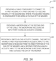
- FIG. 3A illustrates a flow diagram of a method 350 of forming a hearing assistance device, according to various embodiments of the present subject matter.
- the method 350 includes providing a cable configured to connect to a first housing at a first end and to a second housing at the second end, wherein the first housing is configured to be worn above an ear of a wearer and the second housing configured to be worn in the ear of the wearer, at step 352, and providing a microphone at the second end of the cable, the microphone including an input port facing an acoustic channel, at step 354.
- the method also includes providing a switch in the acoustic channel, the switch having a first position in which the acoustic channel is open towards an inner portion of the ear of the wearer and closed away from the inner portion of the ear of the wearer such that acoustic input to the microphone is received from the inner portion of the ear of the wearer, and a second position in which the acoustic channel is open away from the inner portion of the ear of the wearer and closed towards the inner portion of the ear of the wearer such that acoustic input to the microphone is received from an area outside the ear of the wearer.
- the switch includes an acoustic switch.
- the acoustic switch includes one or more of a sliding spool valve, a butterfly valve, a movable membrane valve, a ball valve, a gate valve, or a solenoid valve.
- the switch includes a third position in which the acoustic channel is open towards an inner portion of the ear of the wearer and open away from the inner portion of the ear of the wearer such that acoustic porting is open from the inner portion of the ear of the wearer to the area outside the ear of the wearer, and wherein acoustic input to the microphone is open to the acoustic channel.
- the switch includes a fourth position in which the acoustic channel is open towards an inner portion of the ear of the wearer and open away from the inner portion of the ear of the wearer such that acoustic porting is open from the inner portion of the ear of the wearer to the area outside the ear of the wearer, and wherein acoustic input to the microphone is closed to the acoustic channel.
- the hearing assistance device is a behind-the-ear (BTE) hearing aid, in some embodiments. In some embodiments, the hearing assistance device is a receiver-in-the-canal (RIC) hearing aid.
- a ferromagnetic material is provided and configured to maintain a position of the switch without drawing power from a power supply of the hearing assistance device.
- the switch such as a vent valve
- one or more ferromagnetic features within or outside of the switch or valve can maintain the valve state, without any power requirements from the hearing assistance device electronics. Power from the hearing assistance device electronics is only used briefly to change the vent state, in various embodiments.
- the ferromagnetic material or feature may be positioned to maintain the vent state without drawing power from the hearing aid electronics. For hearing aids with a strained power budget and a limited battery capacity, it is beneficial that the vent only consume power when the vent state is changed.
- FIG. 3B illustrates a flow diagram of a method of using a hearing assistance device, according to various embodiments of the present subject matter.
- the method 360 includes processing sound received through a first acoustic path of a microphone using a processor of a hearing assistance device, wherein the microphone is in a receiver housing configured to be placed in an ear of a wearer of the hearing assistance device, at step 362.
- the method includes actuating a switch in the receiver housing to shift from the first acoustic path to a second acoustic path of the microphone.
- the method further includes processing sound received through the second acoustic path using the processor of the hearing assistance device, at step 366.
- the first acoustic path is open towards an inner portion of the ear of the wearer and closed away from the inner portion of the ear of the wearer such that acoustic input to the microphone is received from the inner portion of the ear of the wearer.
- the second acoustic path is open away from an inner portion of the ear of the wearer and closed towards the inner portion of the ear of the wearer such that acoustic input to the microphone is received from an area outside the ear of the wearer, in various embodiments.
- the switch includes an acoustic switch, such as one or more of a sliding spool valve, a butterfly valve, a movable membrane valve, a ball valve, a gate valve, or a solenoid valve.
- the hearing assistance device may be a behind-the-ear (BTE) hearing aid or a receiver-in-the-canal (RIC) hearing aid, in some embodiments.
- the method may also include using a ferromagnetic material configured to maintain a position of the switch without drawing power from a power supply of the hearing assistance device.
- the microphone is situated on the RIC Cable in the ear canal.
- the microphone port faces into an acoustic channel.
- a switch or vent to change the porting of the acoustic channel to direct the microphone to be such that the sound port is in the "in position” or the "out position".
- the switch or vent can be either mechanically or electromechanically actuated to change the acoustic signal input, in various embodiments.
- the acoustic switch can be a sliding spool style valve, a butterfly style valve, a moveable membrane style valve, a ball style valve, a gate valve, and/or a solenoid style valve.
- the acoustic switch can open to an additional position such that the acoustic porting is fully open from the volume inside the ear to the outside world while the microphone porting is still open to the overall acoustic path.
- the acoustic switch can open such that the acoustic porting is fully open from the volume inside the ear to the outside world while the microphone porting is closed off to the overall acoustic path.
- the microphone and switch are incorporated to a "behind-the-ear" hearing aid, personal sound amplification product (PSAP), over the counter (OTC) hearing device, headphones, hearables, or the like.
- the microphone and switch are incorporated to a "in-the-ear" hearing aid, PSAP, OTC hearing device, headphones, hearables, or the like.
- a physical or mechanical switch or vent can be used.
- an electromechanical switch or vent can be used.
- Benefits of the present subject matter include providing both an inward and outward facing acoustic port using only one microphone.
- the present subject matter eliminates a microphone from the system saving space, and reducing number of microphone signal lines.
- the present subject matter reduces cost of the device, and reduces power consumption thus extending battery life.
- Using the acoustic vent or switch can reduce the number of components in the receiver housing as well as reduce the number of wires and therefore signals that need to be carried by the cable.
- the present subject matter can provide a lower cost of components, fewer data signal inputs, and lengthens an acoustic path to the microphone potentially reducing a likelihood of foreign material ingress to the component.
- the wireless communications may include standard or nonstandard communications.
- standard wireless communications include link protocols including, but not limited to, Bluetooth TM , Bluetooth TM Low Energy (BLE), IEEE 802.11 (wireless LANs), 802.15 (WPANs), 802.16 (WiMAX), cellular protocols including, but not limited to CDMA and GSM, ZigBee, and ultra-wideband (UWB) technologies.
- Such protocols support radio frequency communications and some support infrared communications.
- the present system is demonstrated as a radio system, it is possible that other forms of wireless communications may be used such as ultrasonic, optical, infrared, and others.
- the standards which may be used include past and present standards. It is also contemplated that future versions of these standards and new future standards may be employed without departing from the scope of the present subject matter.
- the wireless communications support a connection from other devices.
- Such connections include, but are not limited to, one or more mono or stereo connections or digital connections having link protocols including, but not limited to 802.3 (Ethernet), 802.4, 802.5, USB, SPI, PCM, ATM, Fibre-channel, Firewire or 1394, InfiniBand, or a native streaming interface.
- link protocols including, but not limited to 802.3 (Ethernet), 802.4, 802.5, USB, SPI, PCM, ATM, Fibre-channel, Firewire or 1394, InfiniBand, or a native streaming interface.
- such connections include all past and present link protocols. It is also contemplated that future versions of these protocols and new future standards may be employed without departing from the scope of the present subject matter.
- Hearing assistance devices typically include at least one enclosure or housing, a microphone, hearing assistance device electronics including processing electronics, and a speaker or "receiver.”
- Hearing assistance devices may include a power source, such as a battery.
- the battery is rechargeable.
- multiple energy sources are employed.
- the microphone is optional.
- the receiver is optional.
- Antenna configurations may vary and may be included within an enclosure for the electronics or be external to an enclosure for the electronics.
- digital hearing assistance devices include a processor.
- programmable gains may be employed to adjust the hearing assistance device output to a wearer's particular hearing impairment.
- the processor may be a digital signal processor (DSP), microprocessor, microcontroller, other digital logic, or combinations thereof.
- DSP digital signal processor
- the processing may be done by a single processor, or may be distributed over different devices.
- the processing of signals referenced in this application may be performed using the processor or over different devices. Processing may be done in the digital domain, the analog domain, or combinations thereof. Processing may be done using subband processing techniques. Processing may be done using frequency domain or time domain approaches. Some processing may involve both frequency and time domain aspects.
- drawings may omit certain blocks that perform frequency synthesis, frequency analysis, analog-to-digital conversion, digital-to-analog conversion, amplification, buffering, and certain types of filtering and processing.
- the processor is adapted to perform instructions stored in one or more memories, which may or may not be explicitly shown. Various types of memory may be used, including volatile and nonvolatile forms of memory.
- the processor or other processing devices execute instructions to perform a number of signal processing tasks. Such embodiments may include analog components in communication with the processor to perform signal processing tasks, such as sound reception by a microphone, or playing of sound using a receiver (i.e., in applications where such transducers are used).
- different realizations of the block diagrams, circuits, and processes set forth herein may be created by one of skill in the art without departing from the scope of the present subject matter.
- hearing assistance devices may embody the present subject matter without departing from the scope of the present disclosure.
- the devices depicted in the figures are intended to demonstrate the subject matter, but not necessarily in a limited, exhaustive, or exclusive sense. It is also understood that the present subject matter may be used with a device designed for use in the right ear or the left ear or both ears of the wearer.
- hearing assistance devices including hearing assistance devices, including but not limited to, behind-the-ear (BTE), in-the-ear (ITE), in-the-canal (ITC), receiver-in-canal (RIC), invisible-in-canal (IIC) or completely-in-the-canal (CIC) type hearing assistance devices.
- BTE behind-the-ear
- ITE in-the-ear
- ITC in-the-canal
- RIC receiver-in-canal
- IIC invisible-in-canal
- CIC completely-in-the-canal
- hearing assistance devices may include devices that reside substantially behind the ear or over the ear.
- Such devices may include hearing assistance devices with receivers associated with the electronics portion of the behind-the-ear device, or hearing assistance devices of the type having receivers in the ear canal of the user, including but not limited to receiver-in-canal (RIC) or receiver-in-the-ear (RITE) designs.
- the present subject matter may also be used in hearing assistance devices generally, such as cochlear implant type hearing devices.
- the present subject matter may also be used in deep insertion devices having a transducer, such as a receiver or microphone.
- the present subject matter may be used in devices whether such devices are standard or custom fit and whether they provide an open or an occlusive design. It is understood that other hearing assistance devices not expressly stated herein may be used in conjunction with the present subject matter.
Landscapes
- Engineering & Computer Science (AREA)
- Health & Medical Sciences (AREA)
- General Health & Medical Sciences (AREA)
- Neurosurgery (AREA)
- Otolaryngology (AREA)
- Physics & Mathematics (AREA)
- Acoustics & Sound (AREA)
- Signal Processing (AREA)
- Manufacturing & Machinery (AREA)
- Headphones And Earphones (AREA)
Claims (15)
- Dispositif d'assistance auditive, comprenant :un premier boîtier (321) configuré pour être porté au-dessus d'une oreille d'un porteur, le premier boîtier incluant des composants électroniques d'assistance auditive ;un second boîtier (328) configuré pour être porté dans l'oreille du porteur, le second boîtier incluant un récepteur configuré pour émettre des signaux traités par les composants électroniques d'assistance auditive ;un câble (323) configuré pour se connecter au premier boîtier à une première extrémité et au second boîtier (328) à la seconde extrémité ;un microphone (208) à la seconde extrémité du câble, le microphone incluant un port d'entrée faisant face à un canal acoustique ; etun commutateur (202) dans le canal acoustique, le commutateur présentant une première position dans laquelle le canal acoustique est ouvert vers une partie interne de l'oreille du porteur et fermé à l'écart de la partie interne de l'oreille du porteur de telle sorte que l'entrée acoustique au microphone (208) soit reçue à partir de la partie interne de l'oreille du porteur, et une deuxième position dans laquelle le canal acoustique est ouvert à l'écart de la partie interne de l'oreille du porteur et fermé vers la partie interne de l'oreille du porteur de telle sorte que l'entrée acoustique au microphone (208) soit reçue à partir d'une zone à l'extérieur de l'oreille du porteur.
- Dispositif selon la revendication 1, dans lequel :
le microphone (208), le canal acoustique et le commutateur (202) sont inclus dans le câble ; ou le microphone (208), le canal acoustique et le commutateur (202) sont inclus dans le second boîtier (328). - Dispositif selon la revendication 1, dans lequel au moins l'un du microphone (208), du canal acoustique et du commutateur (202) sont inclus dans le câble, et dans lequel au moins l'un du microphone (208), du canal acoustique et du commutateur (202) sont inclus dans le second boîtier (328).
- Dispositif selon l'une quelconque des revendications précédentes, dans lequel le commutateur (202) inclut un commutateur acoustique.
- Dispositif selon la revendication 4, dans lequel le commutateur acoustique inclut un ou plusieurs parmi une vanne à tiroir, une vanne papillon, une vanne à membrane mobile, une vanne à boisseau sphérique, une vanne à guillotine ou une électrovanne.
- Dispositif selon l'une quelconque des revendications 1 à 4, dans lequel le commutateur (202) inclut un évent acoustique.
- Dispositif selon l'une quelconque des revendications 1 à 4, dans lequel :le commutateur (202) est configuré pour être actionné mécaniquement ; oule commutateur (202) est configuré pour être actionné électromécaniquement.
- Dispositif selon l'une quelconque des revendications précédentes, dans lequel le premier boîtier (321) inclut un second microphone configuré pour recevoir une entrée acoustique destinée à être traitée par les composants électroniques d'assistance auditive.
- Dispositif selon l'une quelconque des revendications précédentes, dans lequel le commutateur (202) inclut une troisième position dans laquelle le canal acoustique est ouvert vers une partie interne de l'oreille du porteur et ouvert à l'écart de la partie interne de l'oreille du porteur de telle sorte que le port acoustique soit ouvert de la partie interne de l'oreille du porteur vers la zone à l'extérieur de l'oreille du porteur, et dans lequel l'entrée acoustique vers le microphone est ouverte au canal acoustique.
- Dispositif selon la revendication 9, dans lequel le commutateur (202) inclut une quatrième position dans laquelle le canal acoustique est ouvert vers une partie interne de l'oreille du porteur et ouvert à l'écart de la partie interne de l'oreille du porteur de telle sorte que le port acoustique soit ouvert de la partie interne de l'oreille du porteur vers la zone à l'extérieur de l'oreille du porteur, et dans lequel l'entrée acoustique vers le microphone est fermée au canal acoustique.
- Dispositif selon l'une quelconque des revendications précédentes, dans lequel le dispositif d'assistance auditive est une aide auditive à récepteur dans le canal (RIC).
- Procédé, comprenant :le traitement du son reçu par l'intermédiaire d'un premier trajet acoustique d'un microphone à l'aide d'un processeur d'un dispositif d'assistance auditive, dans lequel le microphone est dans un boîtier de récepteur (321) configuré pour être placé dans une oreille d'un porteur du dispositif d'assistance auditive ;l'actionnement d'un commutateur (202) dans le boîtier de récepteur pour passer du premier trajet acoustique à un second trajet acoustique du microphone ; etle traitement du son reçu par l'intermédiaire du second trajet acoustique à l'aide du processeur du dispositif d'assistance auditive ;dans lequel le premier trajet acoustique est ouvert vers une partie interne de l'oreille du porteur et fermé à l'écart de la partie interne de l'oreille du porteur de telle sorte que l'entrée acoustique vers le microphone soit reçue depuis la partie interne de l'oreille du porteur ; etdans lequel le second trajet acoustique est ouvert à l'écart d'une partie interne de l'oreille du porteur et fermé vers la partie interne de l'oreille du porteur de telle sorte que l'entrée acoustique vers le microphone soit reçue à partir d'une zone à l'extérieur de l'oreille du porteur.
- Procédé selon la revendication 12, dans lequel le commutateur (202) inclut un commutateur acoustique.
- Procédé selon la revendication 13, dans lequel le commutateur acoustique inclut un ou plusieurs parmi une vanne à tiroir, une vanne papillon, une vanne à membrane mobile, une vanne à boisseau sphérique, une vanne à guillotine ou une électrovanne.
- Procédé selon la revendication 12 ou la revendication 13, comprenant en outre :
l'utilisation d'un matériau ferromagnétique configuré pour maintenir une position du commutateur sans puiser dans l'alimentation électrique du dispositif d'assistance auditive.
Applications Claiming Priority (2)
| Application Number | Priority Date | Filing Date | Title |
|---|---|---|---|
| US201962937950P | 2019-11-20 | 2019-11-20 | |
| PCT/US2020/070808 WO2021102469A1 (fr) | 2019-11-20 | 2020-11-20 | Dispositif d'aide auditive avec microphone polyvalent |
Publications (2)
| Publication Number | Publication Date |
|---|---|
| EP4082225A1 EP4082225A1 (fr) | 2022-11-02 |
| EP4082225B1 true EP4082225B1 (fr) | 2024-10-09 |
Family
ID=73855000
Family Applications (1)
| Application Number | Title | Priority Date | Filing Date |
|---|---|---|---|
| EP20825408.6A Active EP4082225B1 (fr) | 2019-11-20 | 2020-11-20 | Dispositif d'aide auditive avec microphone polyvalent |
Country Status (3)
| Country | Link |
|---|---|
| US (1) | US11991503B2 (fr) |
| EP (1) | EP4082225B1 (fr) |
| WO (1) | WO2021102469A1 (fr) |
Families Citing this family (5)
| Publication number | Priority date | Publication date | Assignee | Title |
|---|---|---|---|---|
| EP4082225B1 (fr) | 2019-11-20 | 2024-10-09 | Starkey Laboratories, Inc. | Dispositif d'aide auditive avec microphone polyvalent |
| US12200425B2 (en) * | 2021-05-06 | 2025-01-14 | Gn Hearing A/S | Hearing device comprising a receiver module comprising a vent having a vent valve device |
| CN114598959B (zh) * | 2022-03-22 | 2025-08-19 | 听智慧科技(深圳)有限公司 | 入耳式可穿戴设备 |
| US12513475B2 (en) * | 2022-07-28 | 2025-12-30 | Starkey Laboratories, Inc. | Cable connector for hearing device |
| US12200427B1 (en) * | 2024-07-22 | 2025-01-14 | J & D Tech Inc | Audio cable with switchable transmission direction |
Family Cites Families (4)
| Publication number | Priority date | Publication date | Assignee | Title |
|---|---|---|---|---|
| US3798390A (en) | 1972-07-24 | 1974-03-19 | Gould Inc | Hearing aid with valved dual ports |
| EP2835987B1 (fr) * | 2013-12-06 | 2017-08-30 | Oticon A/s | Prothèse auditive à évent régulable |
| US11102576B2 (en) * | 2018-12-31 | 2021-08-24 | Knowles Electronicis, LLC | Audio device with audio signal processing based on acoustic valve state |
| EP4082225B1 (fr) | 2019-11-20 | 2024-10-09 | Starkey Laboratories, Inc. | Dispositif d'aide auditive avec microphone polyvalent |
-
2020
- 2020-11-20 EP EP20825408.6A patent/EP4082225B1/fr active Active
- 2020-11-20 WO PCT/US2020/070808 patent/WO2021102469A1/fr not_active Ceased
- 2020-11-20 US US17/756,220 patent/US11991503B2/en active Active
Also Published As
| Publication number | Publication date |
|---|---|
| EP4082225A1 (fr) | 2022-11-02 |
| US20220417683A1 (en) | 2022-12-29 |
| US11991503B2 (en) | 2024-05-21 |
| WO2021102469A1 (fr) | 2021-05-27 |
Similar Documents
| Publication | Publication Date | Title |
|---|---|---|
| EP4082225B1 (fr) | Dispositif d'aide auditive avec microphone polyvalent | |
| US12356155B2 (en) | Hearing device with neural network-based microphone signal processing | |
| EP3422734B1 (fr) | Embout auriculaire à bride et appareil auditif le comprenant | |
| US10284975B2 (en) | Self-fitting in-canal component and hearing assistance device | |
| EP2835987B1 (fr) | Prothèse auditive à évent régulable | |
| US10297910B2 (en) | Hearing device with bowtie antenna optimized for specific band | |
| EP3257265B1 (fr) | Communication binaurale utilisant un dispositif intermediaire | |
| US9774961B2 (en) | Hearing assistance device ear-to-ear communication using an intermediate device | |
| US10735871B2 (en) | Antenna system with adaptive configuration for hearing assistance device | |
| EP3099082A1 (fr) | Bras de rétention d'ajustement de confort à auto-alignement pour un dispositif d'aide auditive | |
| US9473859B2 (en) | Systems and methods of telecommunication for bilateral hearing instruments | |
| EP3136753B1 (fr) | Antenne à alimentation transversale évasée dans un dispositif d'aide auditive | |
| EP3994898A1 (fr) | Antenne en spirale à polarisation circulaire pour dispositifs d'aide auditive | |
| EP2866472A1 (fr) | Expansion de marge d'étage d'entrée pour des dispositifs d'assistance auditive | |
| US20250024211A1 (en) | Hearing aid and cochlear implant wireless system | |
| US8189836B2 (en) | Ear mold with vent opening through outer ear and corresponding ventilation method | |
| EP3024251A1 (fr) | Combiné de métal collé par frittage |
Legal Events
| Date | Code | Title | Description |
|---|---|---|---|
| STAA | Information on the status of an ep patent application or granted ep patent |
Free format text: STATUS: UNKNOWN |
|
| STAA | Information on the status of an ep patent application or granted ep patent |
Free format text: STATUS: THE INTERNATIONAL PUBLICATION HAS BEEN MADE |
|
| PUAI | Public reference made under article 153(3) epc to a published international application that has entered the european phase |
Free format text: ORIGINAL CODE: 0009012 |
|
| STAA | Information on the status of an ep patent application or granted ep patent |
Free format text: STATUS: REQUEST FOR EXAMINATION WAS MADE |
|
| 17P | Request for examination filed |
Effective date: 20220902 |
|
| AK | Designated contracting states |
Kind code of ref document: A1 Designated state(s): AL AT BE BG CH CY CZ DE DK EE ES FI FR GB GR HR HU IE IS IT LI LT LU LV MC MK MT NL NO PL PT RO RS SE SI SK SM TR |
|
| DAV | Request for validation of the european patent (deleted) | ||
| DAX | Request for extension of the european patent (deleted) | ||
| REG | Reference to a national code |
Ref country code: DE Ref legal event code: R079 Free format text: PREVIOUS MAIN CLASS: H04R0025000000 Ipc: H04R0025020000 Ref document number: 602020039237 Country of ref document: DE |
|
| GRAP | Despatch of communication of intention to grant a patent |
Free format text: ORIGINAL CODE: EPIDOSNIGR1 |
|
| STAA | Information on the status of an ep patent application or granted ep patent |
Free format text: STATUS: GRANT OF PATENT IS INTENDED |
|
| RIC1 | Information provided on ipc code assigned before grant |
Ipc: H04R 25/02 20060101AFI20240501BHEP |
|
| INTG | Intention to grant announced |
Effective date: 20240528 |
|
| GRAS | Grant fee paid |
Free format text: ORIGINAL CODE: EPIDOSNIGR3 |
|
| GRAA | (expected) grant |
Free format text: ORIGINAL CODE: 0009210 |
|
| STAA | Information on the status of an ep patent application or granted ep patent |
Free format text: STATUS: THE PATENT HAS BEEN GRANTED |
|
| P01 | Opt-out of the competence of the unified patent court (upc) registered |
Free format text: CASE NUMBER: APP_47076/2024 Effective date: 20240814 |
|
| AK | Designated contracting states |
Kind code of ref document: B1 Designated state(s): AL AT BE BG CH CY CZ DE DK EE ES FI FR GB GR HR HU IE IS IT LI LT LU LV MC MK MT NL NO PL PT RO RS SE SI SK SM TR |
|
| REG | Reference to a national code |
Ref country code: CH Ref legal event code: EP |
|
| REG | Reference to a national code |
Ref country code: DE Ref legal event code: R096 Ref document number: 602020039237 Country of ref document: DE |
|
| REG | Reference to a national code |
Ref country code: IE Ref legal event code: FG4D |
|
| REG | Reference to a national code |
Ref country code: LT Ref legal event code: MG9D |
|
| REG | Reference to a national code |
Ref country code: AT Ref legal event code: MK05 Ref document number: 1731930 Country of ref document: AT Kind code of ref document: T Effective date: 20241009 |
|
| PG25 | Lapsed in a contracting state [announced via postgrant information from national office to epo] |
Ref country code: NL Free format text: LAPSE BECAUSE OF FAILURE TO SUBMIT A TRANSLATION OF THE DESCRIPTION OR TO PAY THE FEE WITHIN THE PRESCRIBED TIME-LIMIT Effective date: 20241009 |
|
| PG25 | Lapsed in a contracting state [announced via postgrant information from national office to epo] |
Ref country code: NL Free format text: LAPSE BECAUSE OF FAILURE TO SUBMIT A TRANSLATION OF THE DESCRIPTION OR TO PAY THE FEE WITHIN THE PRESCRIBED TIME-LIMIT Effective date: 20241009 |
|
| PG25 | Lapsed in a contracting state [announced via postgrant information from national office to epo] |
Ref country code: IS Free format text: LAPSE BECAUSE OF FAILURE TO SUBMIT A TRANSLATION OF THE DESCRIPTION OR TO PAY THE FEE WITHIN THE PRESCRIBED TIME-LIMIT Effective date: 20250209 Ref country code: HR Free format text: LAPSE BECAUSE OF FAILURE TO SUBMIT A TRANSLATION OF THE DESCRIPTION OR TO PAY THE FEE WITHIN THE PRESCRIBED TIME-LIMIT Effective date: 20241009 Ref country code: PT Free format text: LAPSE BECAUSE OF FAILURE TO SUBMIT A TRANSLATION OF THE DESCRIPTION OR TO PAY THE FEE WITHIN THE PRESCRIBED TIME-LIMIT Effective date: 20250210 |
|
| PG25 | Lapsed in a contracting state [announced via postgrant information from national office to epo] |
Ref country code: FI Free format text: LAPSE BECAUSE OF FAILURE TO SUBMIT A TRANSLATION OF THE DESCRIPTION OR TO PAY THE FEE WITHIN THE PRESCRIBED TIME-LIMIT Effective date: 20241009 |
|
| PG25 | Lapsed in a contracting state [announced via postgrant information from national office to epo] |
Ref country code: BG Free format text: LAPSE BECAUSE OF FAILURE TO SUBMIT A TRANSLATION OF THE DESCRIPTION OR TO PAY THE FEE WITHIN THE PRESCRIBED TIME-LIMIT Effective date: 20241009 |
|
| PG25 | Lapsed in a contracting state [announced via postgrant information from national office to epo] |
Ref country code: ES Free format text: LAPSE BECAUSE OF FAILURE TO SUBMIT A TRANSLATION OF THE DESCRIPTION OR TO PAY THE FEE WITHIN THE PRESCRIBED TIME-LIMIT Effective date: 20241009 |
|
| PG25 | Lapsed in a contracting state [announced via postgrant information from national office to epo] |
Ref country code: NO Free format text: LAPSE BECAUSE OF FAILURE TO SUBMIT A TRANSLATION OF THE DESCRIPTION OR TO PAY THE FEE WITHIN THE PRESCRIBED TIME-LIMIT Effective date: 20250109 |
|
| PG25 | Lapsed in a contracting state [announced via postgrant information from national office to epo] |
Ref country code: LV Free format text: LAPSE BECAUSE OF FAILURE TO SUBMIT A TRANSLATION OF THE DESCRIPTION OR TO PAY THE FEE WITHIN THE PRESCRIBED TIME-LIMIT Effective date: 20241009 Ref country code: AT Free format text: LAPSE BECAUSE OF FAILURE TO SUBMIT A TRANSLATION OF THE DESCRIPTION OR TO PAY THE FEE WITHIN THE PRESCRIBED TIME-LIMIT Effective date: 20241009 Ref country code: GR Free format text: LAPSE BECAUSE OF FAILURE TO SUBMIT A TRANSLATION OF THE DESCRIPTION OR TO PAY THE FEE WITHIN THE PRESCRIBED TIME-LIMIT Effective date: 20250110 |
|
| PG25 | Lapsed in a contracting state [announced via postgrant information from national office to epo] |
Ref country code: PL Free format text: LAPSE BECAUSE OF FAILURE TO SUBMIT A TRANSLATION OF THE DESCRIPTION OR TO PAY THE FEE WITHIN THE PRESCRIBED TIME-LIMIT Effective date: 20241009 |
|
| PG25 | Lapsed in a contracting state [announced via postgrant information from national office to epo] |
Ref country code: RS Free format text: LAPSE BECAUSE OF FAILURE TO SUBMIT A TRANSLATION OF THE DESCRIPTION OR TO PAY THE FEE WITHIN THE PRESCRIBED TIME-LIMIT Effective date: 20250109 |
|
| REG | Reference to a national code |
Ref country code: CH Ref legal event code: PL |
|
| PG25 | Lapsed in a contracting state [announced via postgrant information from national office to epo] |
Ref country code: SM Free format text: LAPSE BECAUSE OF FAILURE TO SUBMIT A TRANSLATION OF THE DESCRIPTION OR TO PAY THE FEE WITHIN THE PRESCRIBED TIME-LIMIT Effective date: 20241009 |
|
| PG25 | Lapsed in a contracting state [announced via postgrant information from national office to epo] |
Ref country code: MC Free format text: LAPSE BECAUSE OF FAILURE TO SUBMIT A TRANSLATION OF THE DESCRIPTION OR TO PAY THE FEE WITHIN THE PRESCRIBED TIME-LIMIT Effective date: 20241009 |
|
| PG25 | Lapsed in a contracting state [announced via postgrant information from national office to epo] |
Ref country code: DK Free format text: LAPSE BECAUSE OF FAILURE TO SUBMIT A TRANSLATION OF THE DESCRIPTION OR TO PAY THE FEE WITHIN THE PRESCRIBED TIME-LIMIT Effective date: 20241009 |
|
| REG | Reference to a national code |
Ref country code: DE Ref legal event code: R097 Ref document number: 602020039237 Country of ref document: DE |
|
| PG25 | Lapsed in a contracting state [announced via postgrant information from national office to epo] |
Ref country code: LU Free format text: LAPSE BECAUSE OF NON-PAYMENT OF DUE FEES Effective date: 20241120 |
|
| REG | Reference to a national code |
Ref country code: CH Ref legal event code: PL |
|
| PG25 | Lapsed in a contracting state [announced via postgrant information from national office to epo] |
Ref country code: EE Free format text: LAPSE BECAUSE OF FAILURE TO SUBMIT A TRANSLATION OF THE DESCRIPTION OR TO PAY THE FEE WITHIN THE PRESCRIBED TIME-LIMIT Effective date: 20241009 |
|
| PG25 | Lapsed in a contracting state [announced via postgrant information from national office to epo] |
Ref country code: CH Free format text: LAPSE BECAUSE OF NON-PAYMENT OF DUE FEES Effective date: 20241130 |
|
| PG25 | Lapsed in a contracting state [announced via postgrant information from national office to epo] |
Ref country code: RO Free format text: LAPSE BECAUSE OF FAILURE TO SUBMIT A TRANSLATION OF THE DESCRIPTION OR TO PAY THE FEE WITHIN THE PRESCRIBED TIME-LIMIT Effective date: 20241009 |
|
| PG25 | Lapsed in a contracting state [announced via postgrant information from national office to epo] |
Ref country code: SK Free format text: LAPSE BECAUSE OF FAILURE TO SUBMIT A TRANSLATION OF THE DESCRIPTION OR TO PAY THE FEE WITHIN THE PRESCRIBED TIME-LIMIT Effective date: 20241009 |
|
| PG25 | Lapsed in a contracting state [announced via postgrant information from national office to epo] |
Ref country code: CZ Free format text: LAPSE BECAUSE OF FAILURE TO SUBMIT A TRANSLATION OF THE DESCRIPTION OR TO PAY THE FEE WITHIN THE PRESCRIBED TIME-LIMIT Effective date: 20241009 |
|
| PG25 | Lapsed in a contracting state [announced via postgrant information from national office to epo] |
Ref country code: IT Free format text: LAPSE BECAUSE OF FAILURE TO SUBMIT A TRANSLATION OF THE DESCRIPTION OR TO PAY THE FEE WITHIN THE PRESCRIBED TIME-LIMIT Effective date: 20241009 |
|
| PLBE | No opposition filed within time limit |
Free format text: ORIGINAL CODE: 0009261 |
|
| STAA | Information on the status of an ep patent application or granted ep patent |
Free format text: STATUS: NO OPPOSITION FILED WITHIN TIME LIMIT |
|
| REG | Reference to a national code |
Ref country code: BE Ref legal event code: MM Effective date: 20241130 |
|
| PG25 | Lapsed in a contracting state [announced via postgrant information from national office to epo] |
Ref country code: SE Free format text: LAPSE BECAUSE OF FAILURE TO SUBMIT A TRANSLATION OF THE DESCRIPTION OR TO PAY THE FEE WITHIN THE PRESCRIBED TIME-LIMIT Effective date: 20241009 |
|
| 26N | No opposition filed |
Effective date: 20250710 |
|
| GBPC | Gb: european patent ceased through non-payment of renewal fee |
Effective date: 20250109 |
|
| PG25 | Lapsed in a contracting state [announced via postgrant information from national office to epo] |
Ref country code: GB Free format text: LAPSE BECAUSE OF NON-PAYMENT OF DUE FEES Effective date: 20250109 Ref country code: BE Free format text: LAPSE BECAUSE OF NON-PAYMENT OF DUE FEES Effective date: 20241130 |
|
| PG25 | Lapsed in a contracting state [announced via postgrant information from national office to epo] |
Ref country code: IE Free format text: LAPSE BECAUSE OF NON-PAYMENT OF DUE FEES Effective date: 20241120 |
|
| PGFP | Annual fee paid to national office [announced via postgrant information from national office to epo] |
Ref country code: DE Payment date: 20251021 Year of fee payment: 6 |
|
| PGFP | Annual fee paid to national office [announced via postgrant information from national office to epo] |
Ref country code: FR Payment date: 20251112 Year of fee payment: 6 |
|
| PG25 | Lapsed in a contracting state [announced via postgrant information from national office to epo] |
Ref country code: HU Free format text: LAPSE BECAUSE OF FAILURE TO SUBMIT A TRANSLATION OF THE DESCRIPTION OR TO PAY THE FEE WITHIN THE PRESCRIBED TIME-LIMIT; INVALID AB INITIO Effective date: 20201120 |
|
| PG25 | Lapsed in a contracting state [announced via postgrant information from national office to epo] |
Ref country code: CY Free format text: LAPSE BECAUSE OF FAILURE TO SUBMIT A TRANSLATION OF THE DESCRIPTION OR TO PAY THE FEE WITHIN THE PRESCRIBED TIME-LIMIT; INVALID AB INITIO Effective date: 20201120 |