EP4082318B1 - Système de traitement extérieur - Google Patents
Système de traitement extérieur Download PDFInfo
- Publication number
- EP4082318B1 EP4082318B1 EP21171257.5A EP21171257A EP4082318B1 EP 4082318 B1 EP4082318 B1 EP 4082318B1 EP 21171257 A EP21171257 A EP 21171257A EP 4082318 B1 EP4082318 B1 EP 4082318B1
- Authority
- EP
- European Patent Office
- Prior art keywords
- movement
- travel
- detection
- outdoor
- designed
- Prior art date
- Legal status (The legal status is an assumption and is not a legal conclusion. Google has not performed a legal analysis and makes no representation as to the accuracy of the status listed.)
- Active
Links
Images


Classifications
-
- A—HUMAN NECESSITIES
- A01—AGRICULTURE; FORESTRY; ANIMAL HUSBANDRY; HUNTING; TRAPPING; FISHING
- A01D—HARVESTING; MOWING
- A01D34/00—Mowers; Mowing apparatus of harvesters
- A01D34/01—Mowers; Mowing apparatus of harvesters characterised by features relating to the type of cutting apparatus
- A01D34/412—Mowers; Mowing apparatus of harvesters characterised by features relating to the type of cutting apparatus having rotating cutters
- A01D34/63—Mowers; Mowing apparatus of harvesters characterised by features relating to the type of cutting apparatus having rotating cutters having cutters rotating about a vertical axis
- A01D34/64—Mowers; Mowing apparatus of harvesters characterised by features relating to the type of cutting apparatus having rotating cutters having cutters rotating about a vertical axis mounted on a vehicle, e.g. a tractor, or drawn by an animal or a vehicle
-
- A—HUMAN NECESSITIES
- A01—AGRICULTURE; FORESTRY; ANIMAL HUSBANDRY; HUNTING; TRAPPING; FISHING
- A01D—HARVESTING; MOWING
- A01D34/00—Mowers; Mowing apparatus of harvesters
- A01D34/006—Control or measuring arrangements
- A01D34/008—Control or measuring arrangements for automated or remotely controlled operation
-
- A—HUMAN NECESSITIES
- A01—AGRICULTURE; FORESTRY; ANIMAL HUSBANDRY; HUNTING; TRAPPING; FISHING
- A01D—HARVESTING; MOWING
- A01D34/00—Mowers; Mowing apparatus of harvesters
- A01D34/01—Mowers; Mowing apparatus of harvesters characterised by features relating to the type of cutting apparatus
- A01D34/412—Mowers; Mowing apparatus of harvesters characterised by features relating to the type of cutting apparatus having rotating cutters
- A01D34/63—Mowers; Mowing apparatus of harvesters characterised by features relating to the type of cutting apparatus having rotating cutters having cutters rotating about a vertical axis
- A01D34/81—Casings; Housings
-
- A—HUMAN NECESSITIES
- A01—AGRICULTURE; FORESTRY; ANIMAL HUSBANDRY; HUNTING; TRAPPING; FISHING
- A01D—HARVESTING; MOWING
- A01D75/00—Accessories for harvesters or mowers
- A01D75/18—Safety devices for parts of the machines
- A01D75/185—Avoiding collisions with obstacles
-
- G—PHYSICS
- G05—CONTROLLING; REGULATING
- G05D—SYSTEMS FOR CONTROLLING OR REGULATING NON-ELECTRIC VARIABLES
- G05D1/00—Control of position, course, altitude or attitude of land, water, air or space vehicles, e.g. using automatic pilots
- G05D1/02—Control of position or course in two dimensions
- G05D1/021—Control of position or course in two dimensions specially adapted to land vehicles
- G05D1/0227—Control of position or course in two dimensions specially adapted to land vehicles using mechanical sensing means, e.g. for sensing treated area
-
- G—PHYSICS
- G05—CONTROLLING; REGULATING
- G05D—SYSTEMS FOR CONTROLLING OR REGULATING NON-ELECTRIC VARIABLES
- G05D1/00—Control of position, course, altitude or attitude of land, water, air or space vehicles, e.g. using automatic pilots
- G05D1/02—Control of position or course in two dimensions
- G05D1/021—Control of position or course in two dimensions specially adapted to land vehicles
- G05D1/0231—Control of position or course in two dimensions specially adapted to land vehicles using optical position detecting means
- G05D1/0238—Control of position or course in two dimensions specially adapted to land vehicles using optical position detecting means using obstacle or wall sensors
-
- G—PHYSICS
- G05—CONTROLLING; REGULATING
- G05D—SYSTEMS FOR CONTROLLING OR REGULATING NON-ELECTRIC VARIABLES
- G05D1/00—Control of position, course, altitude or attitude of land, water, air or space vehicles, e.g. using automatic pilots
- G05D1/20—Control system inputs
- G05D1/24—Arrangements for determining position or orientation
- G05D1/241—Means for detecting physical contact, e.g. touch sensors or bump sensors
-
- A—HUMAN NECESSITIES
- A01—AGRICULTURE; FORESTRY; ANIMAL HUSBANDRY; HUNTING; TRAPPING; FISHING
- A01D—HARVESTING; MOWING
- A01D2101/00—Lawn-mowers
Definitions
- the invention relates to an outdoor processing system.
- the DE 20 2012 102 637 U1 discloses a self-propelled soil tillage device, in particular a robotic lawnmower, wherein the soil tillage device has a chassis, a chassis with a travel drive, a driven processing tool, a controller, a support for a cover movably resting on the chassis and a detection device cooperating with the cover for detecting cover movements, wherein the support has a plurality of bearing points arranged on the chassis, wherein the detection device is arranged functionally and spatially separate from the bearing points.
- the outdoor processing system has an autonomous mobile outdoor processing robot and a sensor and control device.
- the outdoor processing robot has a chassis and a contact element.
- the chassis is designed for a travel movement of the outdoor processing robot in a direction of travel.
- the contact element is designed for an evasive movement in an evasive direction through the travel movement in the direction of travel and a, in particular direct, obstacle contact with a lower contact point below a height limit, and is movably mounted relative to the chassis.
- the contact element is designed for a detection movement in a detection direction through the travel movement in the direction of travel and a, in particular direct, obstacle contact with an upper contact point at or above the height limit, designed and mounted so as to be movable relative to the chassis.
- the evasive direction and the detection direction are, in particular, different from one another.
- the sensor and control device is designed for, in particular, automatic detection, in particular only, the detection movement or a movement caused by the detection movement and for, in particular, automatic control of a protective function of the outdoor processing robot, in particular only or solely triggered by, in particular only, the detected detection movement or the detected movement.
- the sensor and control device does not detect or evaluate the evasive movement or a movement caused by the evasive movement.
- the sensor and control device is not designed to detect the evasive movement or a movement caused by the evasive movement and/or not to control the protective function triggered by the detected evasive movement or the detected movement.
- This enables control of the protective function filtered according to the height of the obstacle.
- This enables, on the one hand, a more robust operation of the outdoor processing robot, especially when touching a high obstacle, and, on the other hand, an undisturbed or unaffected operation of the outdoor processing robot, especially when touching a low obstacle, such as a negligibly small object, in particular by reducing false triggering of the sensor and control device.
- This therefore enables improved operation of the outdoor processing robot.
- the outdoor processing system, the outdoor processing robot and/or the sensor and control device can be electrical.
- the outdoor processing robot can have the sensor and control device.
- Autonomous mobile outdoor processing robot can mean that the outdoor processing robot can be designed to move automatically, independently or self-controlled and/or independently of a user, in particular on an area that can be predetermined and/or limited, and/or to process automatically, independently or self-controlled and/or independently of the user, in particular the area, in particular to start and/or finish the processing.
- the outdoor processing system can be an open or outdoor area processing system or a green area processing system. Additionally or alternatively, the An outdoor processing robot can be an open-air or outdoor area processing robot or a green area processing robot. Additionally or alternatively, the outdoor processing robot can be a garden and/or terrace processing device.
- the chassis can have at least one driven wheel and at least one non-driven wheel for the travel movement of the outdoor processing robot, in particular on the surface.
- At least the non-driven wheel can be arranged in front of at least the driven wheel in the direction of travel, in particular.
- the driving movement in the direction of travel can be a forward movement.
- contact part can be used synonymously for the term “contact element”.
- the obstacle contact can be with a side or front of the contact element facing in the direction of travel or forward.
- the height limit can be defined by at least one section of a shape or a contour or an outline of the contact element. Additionally or alternatively, the height limit can have, in particular be, a contour line. Further additionally or alternatively, the height limit can be referred to as a filter limit.
- the avoidance direction and the detection direction can be opposite to each other.
- the evasive direction is, in particular, at least partially, upwards. Additionally or alternatively, the detection direction is, in particular, at least partially, downwards. This, in particular the evasive direction upwards, makes it possible to avoid the low obstacle.
- the chassis defines or has a driving plane.
- the lower contact point and the upper contact point are arranged along a height direction that is orthogonal to the driving plane.
- the height limit is arranged above the driving plane, in particular in the height direction.
- the avoidance direction is in particular non-orthogonal, in particular parallel, with respect to the height direction, away from the driving plane.
- the detection direction is in particular non-orthogonal, in particular anti-parallel, with respect to the height direction, towards the driving plane.
- the chassis can have running wheels for the driving movement of the outdoor processing robot, in particular on the surface. The running wheels can define the driving plane.
- the driving plane can be horizontal.
- the height direction can be vertical.
- non-orthogonal can mean a deviation, in particular an angular deviation, of a maximum of 30 ° (degrees), in particular a maximum of 20 °, in particular a maximum of 10 °, and/or a minimum of 150 °, in particular a minimum of 160 °, in particular a minimum of 170 °.
- the outdoor processing robot has at least one element swing arm. At least the element swing arm is mounted so as to be rotatable around a rotation axis.
- the rotation axis is arranged non-parallel, in particular orthogonal, with respect to the direction of travel.
- the Contact element connected in such a way that the evasive movement in the evasive direction causes an evasive rotational movement of at least the element swing around the axis of rotation in an evasive rotational direction, in particular directly, and the detection movement in the detection direction causes a detection rotational movement of at least the element swing around the axis of rotation in a detection rotational direction, in particular directly.
- the evasive rotational direction and the detection rotational direction are, in particular, different from one another.
- the sensor and control device is designed for, in particular automatically, detection, in particular only, the detection rotational movement or a movement caused by the detection rotational movement and for, in particular automatically, control of the protective function, in particular only or solely, triggered by, in particular only, the detected detection rotational movement or the detected movement. Furthermore, the sensor and control device does not detect or evaluate the evasive rotational movement or a movement caused by the evasive rotational movement.
- the sensor and control device is not designed to detect the evasive rotational movement or a movement caused by the evasive rotational movement and/or not to control the protective function triggered by the detected evasive rotational movement or the detected movement.
- This enables at least one movement in at least one direction other than above and/or below and/or the height direction.
- the movement in the direction can be easy to detect.
- the term "element carrier” or "element arm” can be used synonymously for the term "element swing arm”.
- at least the element swing arm can be mounted so that it can rotate relative to the chassis.
- non-parallel can mean a deviation, in particular an angular deviation, of at least 60 °, in particular at least 70 °, in particular at least 80 °, and/or at most 120 °, in particular at most 110 °, in particular at most 100 °.
- the axis of rotation can be arranged non-orthogonally, in particular parallel, in relation to the driving plane.
- the axis of rotation can be horizontal.
- the contact element can be connected to at least one free end of at least the element swing arm.
- the contact element can be connected mechanically and/or directly and/or rigidly or firmly to at least the element swing arm.
- at least the element swing arm and the contact element can be integrally formed or in one piece, in particular with one another.
- the evasive direction of rotation and the detection direction of rotation can be opposite to one another.
- At least the element swing is a pushed element swing.
- the axis of rotation is arranged above the height limit, in particular when there is no contact with an obstacle.
- the pushed element swing enables the obstacle to be contacted by the contact element.
- this, in particular the axis of rotation above the height limit enables the avoidance direction and the detection direction to be different.
- the contact element can be arranged in front of the axis of rotation, in particular in the direction of travel.
- the contact element below the height limit has a particularly oblique course from the front top to the bottom and back, particularly against the direction of travel, or is shaped to run from the front top to the bottom and back, particularly when there is no contact with an obstacle.
- the course has an angle to the direction of travel of a maximum of 60°, particularly a maximum of 45°, particularly 30°, and/or a minimum of 10°.
- the contact element on or above the height limit has a course from the front bottom to the top, particularly behind, particularly against the direction of travel, or is shaped to run from the front bottom to the top, particularly behind, particularly when there is no contact with an obstacle.
- At least the course enables, in particular the different courses enable, the evasive movement in the evasive direction and/or the detection movement in the, in particular different, detection direction.
- the course from the front top to the bottom and back can be straight or, in particular outwards, convex.
- the outdoor processing robot has a cover hood.
- the cover hood is arranged above the contact element, in particular.
- the cover hood is mounted movably relative to the chassis, in particular directly.
- the contact element is mounted movably relative to the cover hood in such a way that the detection movement causes a hood movement, in particular against the direction of travel, of the cover hood relative to the chassis, in particular and does not cause the evasive movement.
- the sensor and control device is designed for, in particular automatically, detection of the hood movement or a movement caused by the hood movement and for, in particular automatically, control of the protective function, in particular only or solely triggered by the detected hood movement or the detected movement. This, in particular the hood movement, enables simple detection.
- the cover hood enables protection of the outdoor processing robot, in particular the chassis and/or the sensor and Control device.
- the term "protective hood” can be used synonymously with the term “cover hood”.
- the cover hood can be arranged behind the contact element, in particular against the direction of travel, at the same height and/or below the contact element.
- at least the element rocker can be mounted so that it can rotate, in particular directly, on the cover hood.
- the detection rotary movement can cause the hood movement, in particular directly.
- the evasive rotary movement does not need to or cannot cause the hood movement.
- the wording "to the rear” can be used synonymously with the wording "against the direction of travel”.
- the cover hood is designed, in particular shaped, for the hood movement caused by the driving movement in the direction of travel and a, in particular direct, obstacle contact with a hood point.
- This enables the control of the protective function when touching a particularly high obstacle and/or, in particular thus, a synergy effect.
- the hood point can be arranged above the upper contact point, in particular.
- the cover hood can be designed for the hood movement only or alone and/or directly and/or mechanically and/or caused by the driving movement in the direction of travel and the obstacle contact and/or by the driving movement in the direction of travel and the obstacle contact simultaneously or together or with one another.
- the contact element is suspended by means of a spring and/or on the cover, if present.
- the contact element is designed to, in particular directly, touch or rest on a surface, in particular the surface to be worked on.
- the suspension makes it easier to make the evasive movement in the evasive direction, in particular upwards.
- this, in particular the contact with the surface makes it possible to define the height limit, in particular above the driving level.
- the spring can be a helical and/or tension spring.
- the surface can be worked on using the outdoor processing robot.
- the surface can be an open space, in particular an unsealed floor, or a green space, such as a meadow with grass.
- the surface can be an area with paving slabs, patio tiles and/or paving stones.
- the contact element is designed to slide, in particular to glide, on the surface, in particular as a runner. Additionally or alternatively, the contact element is designed to roll on the surface, in particular as a roller.
- the term “slide” can be used synonymously with the term "runner”.
- the outdoor processing robot has a processing tool.
- the contact element is arranged in front of the processing tool, in particular in the direction of travel. This enables the control of the protective function for more robust operation, in particular when moving in the direction of travel.
- the processing tool can be designed to process the surface.
- the processing tool can have, in particular be, a cutting tool.
- the processing tool can have, in particular be, a cleaning tool, in particular a wire brush.
- the outdoor processing robot has a processing tool, in particular the processing tool.
- the processing tool has a lawn mowing tool, in particular the lawn mowing tool.
- the outdoor processing robot is designed as a lawn mowing robot.
- the lawn mowing tool can be designed to mow the area.
- the lawn mowing tool can have at least one mowing line, at least one plastic blade, at least one metal blade and/or a metal cutting blade with at least one cutting edge and/or with at least one cutting tooth.
- the lawn mowing robot can be a mulching mowing robot.
- the outdoor processing robot has a tool system.
- the tool system has a processing tool, in particular the processing tool.
- the sensor and control device is designed for, in particular, automatic control, in particular for deactivation, of the tool system as the protective function.
- the outdoor processing robot has a driving system.
- the driving system has the chassis.
- the sensor and control device is designed for, in particular, automatic control, in particular for deactivation, of the driving system as the protective function. This enables more robust operation.
- the tool system and/or the driving system can be electrical and/or controllable.
- the tool system can have a, in particular electrical and/or controllable, drive motor for driving and/or moving the processing tool.
- the processing tool can be drivable and/or movable. In addition or alternatively, the processing tool can be designed to process the surface. In addition or alternatively, the processing tool can have, in particular, a cutting tool. In addition or alternatively, the processing tool can have, in particular, a cleaning tool, in particular a wire brush.
- the driving system can have a drive motor, in particular an electric and/or controllable one, for driving and/or moving at least the driven impeller.
- the sensor and control device for controlling the driving system for movement around the, in particular high, obstacle and/or away from the, in particular high, obstacle can be designed as the protective function.
- the term "stopping" can be used synonymously for the term "deactivation".
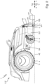
- Fig. 1 to 4 show an outdoor processing system 1 according to the invention.
- the outdoor processing system 1 has an autonomous mobile outdoor processing robot 2 and a sensor and control device 3.
- the outdoor processing robot 2 has a chassis 4 and a contact element 5.
- the chassis 4 is designed for a travel movement of the outdoor processing robot 2 in a, in particular horizontal, direction of travel x, in particular moves and drives.
- the contact element 5 is designed for an evasive movement in an evasive direction z through the travel movement in the direction of travel x and an obstacle contact or a contact with an, in particular low, obstacle uH with a lower contact point uP below a height limit HG and is movably mounted relative to the chassis 4, in particular touches and moves and thus evades.
- the contact element 5 is designed for a detection movement in a detection direction -z through the travel movement in the direction of travel x and an obstacle contact or a contact with a, in particular high, obstacle oH with an upper contact point oP at or above the height limit HG and is movably mounted relative to the chassis 4, in particular touches and moves and thus detects.
- the evasive direction z and the detection direction -z are different.
- the sensor and control device 3 is designed to detect the detection movement or a movement caused by the detection movement and to control a protective function SF of the outdoor processing robot 2 triggered by the detected detection movement or the detected movement, in particular detects and thus controls. In addition, the sensor and control device 3 does not detect or evaluate the evasive movement or a movement caused by the evasive movement.
- the avoidance direction z is upwards.
- the detection direction is -z downwards.
- chassis 4 has a driving plane 4E.
- the lower contact point uP and the upper contact point oP are along a height direction z that is orthogonal to the driving plane 4E.
- the height limit HG in particular in the height direction z, is above the driving level 4E.
- the avoidance direction z is in particular non-orthogonal, in particular parallel, with respect to the height direction z, away from the driving plane 4E.
- the detection direction -z is in particular non-orthogonal, in particular antiparallel, with respect to the height direction z, towards the driving plane 4E.
- the outdoor processing robot 2 has at least one element swing arm 6. At least the element swing arm 6 is mounted so as to be rotatable about an axis of rotation 6A.
- the axis of rotation 6A is non-parallel, in particular orthogonal, with respect to the direction of travel x.
- the contact element 5 is connected to at least the element swing arm 6 in such a way that the evasive movement in the evasive direction z causes an evasive rotational movement of at least the element swing arm 6 around the axis of rotation 6A in an evasive rotational direction r and the detection movement in the detection direction -z causes a detection rotational movement of at least the element swing arm 6 around the axis of rotation 6A in a detection rotational direction -r.
- the evasive rotational direction r and the detection rotational direction -r are different.
- the sensor and control device 3 is designed to detect the detection rotary movement or a movement caused by the detection rotary movement and to control the protective function SF triggered by the detected detection rotary movement or the detected movement, in particular it detects and controls it. Furthermore, the sensor and control device 3 does not detect or evaluate the evasive rotary movement or a movement caused by the evasive rotary movement.
- the outdoor processing robot 2 has two element swings 6. In alternative embodiments, the outdoor processing robot can have only a single element swing or at least three element swings.
- At least the element swing arm 6 is a pushed element swing arm 6 ⁇ .
- the rotation axis 6A is above the height limit HG, in particular when there is no contact with an obstacle.
- the contact element 5 extends from the right, in particular a right side, to the left, in particular to a left side, of the outdoor processing robot 2 or non-parallel, in particular orthogonal, with respect to the direction of travel x and/or non-parallel, in particular orthogonal, with respect to the height direction z and/or non-orthogonal, in particular parallel, with respect to the travel plane 4E and/or the axis of rotation 6A.
- the contact element below the height limit HG has a course from the front top to the bottom rear, in particular against the direction of travel -x, in particular when there is no contact with an obstacle.
- the course has at least an angle ⁇ to the, in particular horizontal, direction of travel x of at least 10 ° and/or a maximum of 60 °, in particular when there is no contact with an obstacle.
- the course has a length L of at least 5 mm (millimeters) and/or a maximum of 100 mm.
- the contact element 5 on or above the height limit HG has a course from the front bottom to the top, in particular to the rear, in particular against the direction of travel -x, in particular when there is no contact with an obstacle.
- the outdoor processing robot 2 has a cover 7.
- the cover 7 is above the contact element 5.
- the cover 7 is movably mounted relative to the chassis 4.
- the contact element 5 is movably mounted relative to the cover 7 such that the detection movement causes a hood movement, in particular against the direction of travel -x, of the cover 7 relative to the chassis 4, and in particular does not cause the evasive movement.
- the sensor and control device 3 is designed to detect the hood movement or a movement caused by the hood movement and to control the protective function SF triggered by the detected hood movement or the detected movement, in particular detects and thus controls.
- the cover hood 7 is designed for the hood movement through the travel movement in the direction of travel x and an obstacle contact with a hood point 7P.
- At least the element swing arm 6 is rotatably mounted on the cover hood 7, in particular by means of at least one rotary joint.
- the detection rotational movement causes the hood movement, in particular and does not cause the evasive rotational movement.
- the sensor and control device 3 has a Hall sensor, which in the embodiment shown is fixedly arranged relative to the chassis 4, in particular is attached to it.
- the sensor and control device 3 also has a magnet, which in the embodiment shown is fixedly arranged relative to the cover 7, in particular is attached to it.
- the Hall sensor is designed, in particular, to detect a relative movement of the magnet, in particular to detect the hood movement.
- the Hall sensor can be fixedly arranged relative to the cover and the magnet can be fixedly arranged relative to the chassis.
- the sensor and control device can have a switch and/or a button.
- the contact element 5 is suspended by means of a spring 8 and/or on the cover 7.
- the contact element 5 is designed to contact, in particular touch, a surface 100 to be processed.
- the contact element 5 is designed to slide on the surface 100, in particular as a runner 5', in particular slides.
- the contact element can be designed to roll on the surface, in particular as a roller, in particular wherein the roller, due to its diameter, rolls in particular only over the low obstacle and not over the high obstacle.
- the outdoor processing robot 2 has a processing tool 9.
- the contact element 5 is in front of the machining tool 9, in particular in the direction of travel x.
- the processing tool 9 has a lawn mowing tool 9'.
- the outdoor processing robot 2 is designed as a lawn mower robot 2'.
- the outdoor processing robot 2 has a tool system 10.
- the tool system 10 has a processing tool 9.
- the sensor and control device 3 is designed to control, in particular to deactivate, the tool system 10 as the protective function SF, in particular controls, in particular deactivates.
- the outdoor processing robot 2 has a driving system 11.
- the driving system 11 has the chassis 4.
- the sensor and control device 3 is designed to control, in particular to deactivate, the driving system 11 as the protective function SF, in particular controls, in particular deactivates.
- the sensor and control device 3 for controlling the driving system 11 for movement around the, in particular high, obstacle oH and/or away from the, in particular high, obstacle oH is designed as the protective function SF.
- the skid 5' When the high or steeply rising obstacle oH is touched, the skid 5' does not drive over it, but is pushed downwards by it, in particular by the continued travel of the chassis 4, at least the element swing 6 locks, the cover 7 is moved or swung out or deflected, in particular to the rear, and the sensor and control device 3 detects and controls or strikes. In particular, the sensor and control device 3 recognizes or detects this as a collision and changes the direction of movement of the outdoor processing robot 2, in particular turns and moves it away from the high obstacle oH. Thus, the processing tool 9, in particular the lawn mowing tool 9', does not process the high obstacle oH.
- the skid 5' moves over it or is pushed upwards by it, in particular by the continued travel of the chassis 4, at least the element swing arm 6 pivots, the cover hood 7 is not moved and the sensor and control device 3 does not detect anything and/or control anything.
- the invention provides an advantageous outdoor processing system which has improved properties in particular enables improved operation of an outdoor processing robot.
Landscapes
- Life Sciences & Earth Sciences (AREA)
- Environmental Sciences (AREA)
- Engineering & Computer Science (AREA)
- Physics & Mathematics (AREA)
- Aviation & Aerospace Engineering (AREA)
- Radar, Positioning & Navigation (AREA)
- Remote Sensing (AREA)
- General Physics & Mathematics (AREA)
- Automation & Control Theory (AREA)
- Electromagnetism (AREA)
- Control Of Position, Course, Altitude, Or Attitude Of Moving Bodies (AREA)
Claims (13)
- Système de traitement en extérieur (1),- le système de traitement en extérieur (1) possédant un robot de traitement en extérieur (2) mobile autonome et un dispositif capteur et de commande (3),- le robot de traitement en extérieur (2) possédant un châssis roulant (4) et un élément de contact (5),- le châssis roulant (4) étant configuré pour un mouvement de déplacement du robot de traitement en extérieur (2) dans une direction de déplacement (x), et- l'élément de contact (5) étant configuré pour un mouvement d'évitement dans une direction d'évitement (z) par le mouvement de déplacement dans la direction de déplacement (x) et un contact d'obstacle avec un point de contact inférieur (uP) en dessous d'une limite de hauteur (HG) et pour un mouvement de détection dans une direction de détection (-z) par le mouvement de déplacement dans la direction de déplacement (x) et un contact d'obstacle avec un point de contact supérieur (oP) sur ou au-dessus de la limite de hauteur (HG) et étant monté mobile par rapport au châssis roulant (4), la direction d'évitement (z) et la direction de détection (-z) étant différentes, caractérisé en ce que le dispositif capteur et de commande (3) est configuré pour détecter le mouvement de détection de l'élément de contact (5) ou un mouvement provoqué par le mouvement de détection et pour commander une fonction de protection (SF) du robot de traitement en extérieur (2) déclenchée par le mouvement de détection détecté ou le mouvement détecté, et- le dispositif capteur et de commande (3) est configuré pour ne pas détecter ou ne pas évaluer le mouvement d'évitement de l'élément de contact (5) ou un mouvement provoqué par le mouvement d'évitement.
- Système de traitement en extérieur (1) selon la revendication 1,- la direction d'évitement (z) étant vers le haut, et/ou- la direction de détection (-z) étant vers le bas.
- Système de traitement en extérieur (1) selon l'une des revendications précédentes,- le châssis roulant (4) possédant un plan de déplacement (4E), et- le point de contact inférieur (uP) et le point de contact supérieur (oP) étant le long d'un sens de la hauteur (z) qui est orthogonal par rapport au plan de déplacement (4E), et/ou- la limite de hauteur (HG), notamment dans le sens de la hauteur (z), se trouvant au-dessus du plan de déplacement (4E), et/ou- la direction d'évitement (z), notamment non orthogonale, en particulier parallèle, par rapport au sens de la hauteur (z), s'éloignant du plan de déplacement (4E), et/ou- la direction de détection (-z), notamment non orthogonale, en particulier antiparallèle, par rapport au sens de la hauteur (z), se rapprochant du plan de déplacement (4E).
- Système de traitement en extérieur (1) selon l'une des revendications précédentes,- le robot de traitement en extérieur (2) possédant au moins un bras oscillant d'élément (6),- au moins le bras oscillant d'élément (6) étant monté mobile en rotation autour d'un axe de rotation (6A), l'axe de rotation (6A) étant non parallèle, notamment orthogonal, par rapport à la direction de déplacement (x), et- l'élément de contact (5) étant relié au moins au bras oscillant d'élément (6) de telle sorte que le mouvement d'évitement dans la direction d'évitement (z) provoque un mouvement de rotation d'évitement d'au moins le bras oscillant d'élément (6) autour de l'axe de rotation (6A) dans un sens de rotation d'évitement (r) et le mouvement de détection dans la direction de détection (-z) provoque un mouvement de rotation de détection d'au moins le bras oscillant d'élément (6) autour de l'axe de rotation (6A) dans un sens de rotation de détection (-r), le sens de rotation d'évitement (r) et le sens de rotation de détection (-r) étant différents, et- le dispositif capteur et de commande (3) étant configuré pour détecter le mouvement de rotation de détection ou un mouvement provoqué par le mouvement de rotation de détection et pour commander la fonction de protection (SF) déclenchée par le mouvement de rotation de détection détecté ou le mouvement détecté, et- le dispositif capteur et de commande (3) ne détectant pas ou n'évaluant pas le mouvement de rotation d'évitement ou un mouvement provoqué par le mouvement de rotation d'évitement.
- Système de traitement en extérieur (1) selon la revendication 4,- au moins le bras oscillant d'élément (6) étant un bras oscillant d'élément poussé (6'), et/ou- l'axe de rotation (6A) se trouvant au-dessus de la limite de hauteur (HG), notamment lorsqu'il n'y a pas de contact d'obstacle.
- Système de traitement en extérieur (1) selon l'une des revendications précédentes,- l'élément de contact (5) présentant, en dessous de la limite de hauteur (HG), un tracé de l'avant en haut vers l'arrière en bas, notamment à l'opposé de la direction de déplacement (-x), en particulier avec un angle (α) par rapport à la direction de déplacement (x) au maximum de 60°, notamment au maximum de 45°, notamment de 30°, notamment lorsqu'il n'y a pas de contact d'obstacle, et/ou- l'élément de contact (5) présentant, sur ou au-dessus de la limite de hauteur (HG), un tracé de l'avant en bas vers le haut, notamment vers l'arrière, notamment à l'opposé de la direction de déplacement (-x), notamment lorsqu'il n'y a pas de contact d'obstacle.
- Système de traitement en extérieur (1) selon l'une des revendications précédentes,- le robot de traitement en extérieur (2) possédant un capot de protection (7),- le capot de protection (7) se trouvant au-dessus de l'élément de contact (5) et étant monté mobile par rapport au châssis roulant (4), et- l'élément de contact (5) étant monté mobile par rapport au capot de protection (7) de telle sorte que le mouvement de détection provoque un mouvement de capot, notamment à l'opposé de la direction de déplacement (-x), du capot de protection (7) par rapport au châssis roulant (4), en particulier et pas le mouvement d'évitement, et- le dispositif capteur et de commande (3) étant configuré pour détecter le mouvement de capot ou un mouvement provoqué par le mouvement de capot et pour commander la fonction de protection (SF) déclenchée par le mouvement de capot détecté ou le mouvement détecté.
- Système de traitement en extérieur (1) selon la revendication 7,- le capot de protection (7) étant configuré pour le mouvement de capot par le mouvement de déplacement dans la direction de déplacement (x) et un contact d'obstacle avec un point de capot (7P).
- Système de traitement en extérieur (1) selon l'une des revendications précédentes, notamment selon la revendication 7 ou 8,- l'élément de contact (5) étant suspendu au moyen d'un ressort (8) et/ou au capot de protection (7), et/ou- l'élément de contact (5) étant configuré pour un contact avec une surface (100) à traiter.
- Système de traitement en extérieur (1) selon la revendication 9,- l'élément de contact (5) étant configuré pour glisser sur la surface (100), notamment sous la forme d'un patin (5'), et/ou- l'élément de contact (5) étant configuré pour rouler sur la surface (100), notamment sous la forme d'un rouleau.
- Système de traitement en extérieur (1) selon l'une des revendications précédentes,- le robot de traitement en extérieur (2) possédant un outil de traitement (9),- l'élément de contact (5) se trouvant devant l'outil de traitement (9), notamment dans la direction de déplacement (x).
- Système de traitement en extérieur (1) selon l'une des revendications précédentes,- le robot de traitement en extérieur (2) possédant un outil de traitement (9), l'outil de traitement (9) possédant un outil de tonte de gazon (9'), et/ou- le robot de traitement en extérieur (2) étant réalisé sous la forme d'un robot de tonte de gazon (2').
- Système de traitement en extérieur (1) selon l'une des revendications précédentes,- le robot de traitement en extérieur (2) possédant un système d'outils (10), le système d'outils (10) possédant un outil de traitement (9), et le dispositif capteur et de commande (3) étant configuré pour commander, notamment pour désactiver, le système d'outils (10) en tant que fonction de protection (SF), et/ou- le robot de traitement en extérieur (2) possédant un système de déplacement (11), le système de déplacement (11) possédant le châssis roulant (4), et le dispositif capteur et de commande (3) étant configuré pour commander, notamment pour désactiver, le système de déplacement (11) en tant que fonction de protection (SF).
Priority Applications (3)
| Application Number | Priority Date | Filing Date | Title |
|---|---|---|---|
| EP21171257.5A EP4082318B1 (fr) | 2021-04-29 | 2021-04-29 | Système de traitement extérieur |
| US17/731,848 US12178153B2 (en) | 2021-04-29 | 2022-04-28 | Outdoor treatment system with robot contact element for avoidance movement |
| CN202210464264.7A CN115250723A (zh) | 2021-04-29 | 2022-04-29 | 户外加工系统 |
Applications Claiming Priority (1)
| Application Number | Priority Date | Filing Date | Title |
|---|---|---|---|
| EP21171257.5A EP4082318B1 (fr) | 2021-04-29 | 2021-04-29 | Système de traitement extérieur |
Publications (2)
| Publication Number | Publication Date |
|---|---|
| EP4082318A1 EP4082318A1 (fr) | 2022-11-02 |
| EP4082318B1 true EP4082318B1 (fr) | 2024-11-20 |
Family
ID=75746295
Family Applications (1)
| Application Number | Title | Priority Date | Filing Date |
|---|---|---|---|
| EP21171257.5A Active EP4082318B1 (fr) | 2021-04-29 | 2021-04-29 | Système de traitement extérieur |
Country Status (3)
| Country | Link |
|---|---|
| US (1) | US12178153B2 (fr) |
| EP (1) | EP4082318B1 (fr) |
| CN (1) | CN115250723A (fr) |
Families Citing this family (1)
| Publication number | Priority date | Publication date | Assignee | Title |
|---|---|---|---|---|
| WO2022195840A1 (fr) * | 2021-03-19 | 2022-09-22 | 本田技研工業株式会社 | Robot |
Family Cites Families (20)
| Publication number | Priority date | Publication date | Assignee | Title |
|---|---|---|---|---|
| DE2210781A1 (de) | 1972-03-07 | 1973-09-13 | Lutz Dipl Ing Schieferdecker | Rasenmaeher |
| GB9310526D0 (en) | 1993-05-21 | 1993-07-07 | Siron Dev Limited | Grass cutting device |
| JP2000139156A (ja) * | 1998-11-02 | 2000-05-23 | Kochi Prefecture | 刈り払い装置及び刈り払い方法 |
| JP2005176792A (ja) * | 2003-12-24 | 2005-07-07 | Atex Co Ltd | 乗用草刈機 |
| DE102006038553A1 (de) | 2006-08-17 | 2008-02-21 | Robert Bosch Gmbh | Autonom arbeitender Rasenmäher |
| JP4886569B2 (ja) * | 2007-03-28 | 2012-02-29 | 株式会社クボタ | 刈取収穫機の刈取昇降制御装置 |
| DE202012102637U1 (de) * | 2012-07-17 | 2013-10-21 | Al-Ko Kober Se | Selbstfahrendes Bodenbearbeitungsgerät |
| EP2803255B1 (fr) | 2013-05-15 | 2017-07-05 | Viking GmbH | Appareil de travail automobile avec détection d'obstacles |
| GB2529849B (en) * | 2014-09-03 | 2017-06-14 | Dyson Technology Ltd | A robot cleaner |
| US9807930B1 (en) | 2016-08-25 | 2017-11-07 | Irobot Corporation | Blade guard for a robot lawnmower |
| EP3508048B1 (fr) * | 2016-08-31 | 2023-10-18 | Positec Power Tools (Suzhou) Co., Ltd | Tondeuse à gazon autonome et procédé de reconnaissance d'un obstacle par une tondeuse à gazon autonome |
| JP7023530B2 (ja) * | 2017-06-07 | 2022-02-22 | 学校法人千葉工業大学 | 自走式掃除機 |
| CN212278869U (zh) | 2017-11-14 | 2021-01-05 | 苏州宝时得电动工具有限公司 | 自移动设备及智能割草机 |
| AU2018438158B2 (en) * | 2018-08-28 | 2024-05-30 | Techtronic Cordless Gp | An autonomous lawn mower and a system for navigating thereof |
| US11934196B1 (en) * | 2018-12-13 | 2024-03-19 | Hydro-Gear Limited Partnership | Visual identifiers for docking and zoning an autonomous mower |
| CN212164220U (zh) * | 2019-09-10 | 2020-12-18 | 丰疆智能科技股份有限公司 | 割草机械 |
| CN112449843A (zh) * | 2019-11-15 | 2021-03-09 | 丰疆智能科技股份有限公司 | 调高装置和带有调高装置的割草机 |
| JP2021101619A (ja) * | 2019-12-24 | 2021-07-15 | 本田技研工業株式会社 | 自律走行作業機 |
| CN112425344A (zh) * | 2020-11-25 | 2021-03-02 | 西南大学 | 一种果园自走式除草机及其自主导航避障方法 |
| CN112586194B (zh) * | 2020-12-24 | 2021-12-14 | 秦宝贵 | 一种方便避开障碍物的草坪修剪机 |
-
2021
- 2021-04-29 EP EP21171257.5A patent/EP4082318B1/fr active Active
-
2022
- 2022-04-28 US US17/731,848 patent/US12178153B2/en active Active
- 2022-04-29 CN CN202210464264.7A patent/CN115250723A/zh active Pending
Also Published As
| Publication number | Publication date |
|---|---|
| EP4082318A1 (fr) | 2022-11-02 |
| US12178153B2 (en) | 2024-12-31 |
| CN115250723A (zh) | 2022-11-01 |
| US20220346309A1 (en) | 2022-11-03 |
Similar Documents
| Publication | Publication Date | Title |
|---|---|---|
| EP3412129B1 (fr) | Robot de traitement d'espaces verts mobile, autonome | |
| EP2687077B1 (fr) | Tondeuse robotisée | |
| DE202018100828U1 (de) | Rasenmäher | |
| DE202020005783U1 (de) | Automatischer Rasenmäher | |
| EP4082318B1 (fr) | Système de traitement extérieur | |
| DE112022001682T5 (de) | Mähroboter | |
| DE60205226T2 (de) | Buschmäherfahrzeug | |
| EP2849620B1 (fr) | Appareil de nettoyage du sol se déplaçant et se dirigeant de manière autonome ainsi que procédé destiné à commander son déplacement | |
| DE202007001567U1 (de) | Schutzring für Pfosten-Freimäher | |
| DE69403511T2 (de) | Heuwerbungsmaschine | |
| DE10139989A1 (de) | Vorrichtung zum mechanischen Abtragen von Wildkraut | |
| EP3975716B1 (fr) | Dispositif pour traiter des plantes au moyen d'un applicateur agencé sur un bras tiré et/ou poussé par un véhicule, véhicule pourvu d'un dispositif de ce type et utilisation d'un dispositif de ce type | |
| EP3923696A1 (fr) | Dispositif, de préférence dispositif robotique autonome, destiné à tondre le gazon | |
| EP4338650A1 (fr) | Procédé de fonctionnement d'un engin mobile automoteur | |
| DE102009052182B4 (de) | Flächen- und Kantenschneider für Grünflächen | |
| EP2481333B1 (fr) | Appareil de traitement de surface mobile, prenant un chemin aléatoire | |
| DE2456383A1 (de) | Ackerbaugeraet mit rotierenden bearbeitungsorganen und einem verbesserten abstuetzorgan fuer dieselben | |
| DE10139990A1 (de) | Vorrichtung zum mechanischen Abtragen von Wildkraut | |
| EP1327383B1 (fr) | Debroussailleuse | |
| DE29918769U1 (de) | Kehrmaschine | |
| EP3735812A1 (fr) | Moissonneuse | |
| DE1482175B2 (de) | Kreiselheuwerbungsmaschine | |
| DE1507302A1 (de) | Maehmaschine | |
| DE2006747A1 (de) | Fahrbare Kehrsaugmaschine | |
| EP3208383A1 (fr) | Balayeuse manuelle |
Legal Events
| Date | Code | Title | Description |
|---|---|---|---|
| PUAI | Public reference made under article 153(3) epc to a published international application that has entered the european phase |
Free format text: ORIGINAL CODE: 0009012 |
|
| STAA | Information on the status of an ep patent application or granted ep patent |
Free format text: STATUS: THE APPLICATION HAS BEEN PUBLISHED |
|
| AK | Designated contracting states |
Kind code of ref document: A1 Designated state(s): AL AT BE BG CH CY CZ DE DK EE ES FI FR GB GR HR HU IE IS IT LI LT LU LV MC MK MT NL NO PL PT RO RS SE SI SK SM TR |
|
| STAA | Information on the status of an ep patent application or granted ep patent |
Free format text: STATUS: REQUEST FOR EXAMINATION WAS MADE |
|
| 17P | Request for examination filed |
Effective date: 20230414 |
|
| RBV | Designated contracting states (corrected) |
Designated state(s): AL AT BE BG CH CY CZ DE DK EE ES FI FR GB GR HR HU IE IS IT LI LT LU LV MC MK MT NL NO PL PT RO RS SE SI SK SM TR |
|
| REG | Reference to a national code |
Ref country code: DE Ref legal event code: R079 Free format text: PREVIOUS MAIN CLASS: A01D0034000000 Ipc: G05D0001000000 Ref country code: DE Ref legal event code: R079 Ref document number: 502021005840 Country of ref document: DE Free format text: PREVIOUS MAIN CLASS: A01D0034000000 Ipc: G05D0001000000 |
|
| GRAP | Despatch of communication of intention to grant a patent |
Free format text: ORIGINAL CODE: EPIDOSNIGR1 |
|
| STAA | Information on the status of an ep patent application or granted ep patent |
Free format text: STATUS: GRANT OF PATENT IS INTENDED |
|
| RIC1 | Information provided on ipc code assigned before grant |
Ipc: A01D 75/18 20060101ALI20240524BHEP Ipc: A01D 34/00 20060101ALI20240524BHEP Ipc: G05D 1/00 20060101AFI20240524BHEP |
|
| INTG | Intention to grant announced |
Effective date: 20240620 |
|
| GRAS | Grant fee paid |
Free format text: ORIGINAL CODE: EPIDOSNIGR3 |
|
| GRAA | (expected) grant |
Free format text: ORIGINAL CODE: 0009210 |
|
| STAA | Information on the status of an ep patent application or granted ep patent |
Free format text: STATUS: THE PATENT HAS BEEN GRANTED |
|
| AK | Designated contracting states |
Kind code of ref document: B1 Designated state(s): AL AT BE BG CH CY CZ DE DK EE ES FI FR GB GR HR HU IE IS IT LI LT LU LV MC MK MT NL NO PL PT RO RS SE SI SK SM TR |
|
| REG | Reference to a national code |
Ref country code: GB Ref legal event code: FG4D Free format text: NOT ENGLISH |
|
| REG | Reference to a national code |
Ref country code: CH Ref legal event code: EP |
|
| REG | Reference to a national code |
Ref country code: DE Ref legal event code: R096 Ref document number: 502021005840 Country of ref document: DE |
|
| REG | Reference to a national code |
Ref country code: IE Ref legal event code: FG4D Free format text: LANGUAGE OF EP DOCUMENT: GERMAN |
|
| REG | Reference to a national code |
Ref country code: LT Ref legal event code: MG9D |
|
| REG | Reference to a national code |
Ref country code: NL Ref legal event code: MP Effective date: 20241120 |
|
| PG25 | Lapsed in a contracting state [announced via postgrant information from national office to epo] |
Ref country code: IS Free format text: LAPSE BECAUSE OF FAILURE TO SUBMIT A TRANSLATION OF THE DESCRIPTION OR TO PAY THE FEE WITHIN THE PRESCRIBED TIME-LIMIT Effective date: 20250320 Ref country code: PT Free format text: LAPSE BECAUSE OF FAILURE TO SUBMIT A TRANSLATION OF THE DESCRIPTION OR TO PAY THE FEE WITHIN THE PRESCRIBED TIME-LIMIT Effective date: 20250320 Ref country code: HR Free format text: LAPSE BECAUSE OF FAILURE TO SUBMIT A TRANSLATION OF THE DESCRIPTION OR TO PAY THE FEE WITHIN THE PRESCRIBED TIME-LIMIT Effective date: 20241120 |
|
| PG25 | Lapsed in a contracting state [announced via postgrant information from national office to epo] |
Ref country code: FI Free format text: LAPSE BECAUSE OF FAILURE TO SUBMIT A TRANSLATION OF THE DESCRIPTION OR TO PAY THE FEE WITHIN THE PRESCRIBED TIME-LIMIT Effective date: 20241120 Ref country code: NL Free format text: LAPSE BECAUSE OF FAILURE TO SUBMIT A TRANSLATION OF THE DESCRIPTION OR TO PAY THE FEE WITHIN THE PRESCRIBED TIME-LIMIT Effective date: 20241120 |
|
| PG25 | Lapsed in a contracting state [announced via postgrant information from national office to epo] |
Ref country code: BG Free format text: LAPSE BECAUSE OF FAILURE TO SUBMIT A TRANSLATION OF THE DESCRIPTION OR TO PAY THE FEE WITHIN THE PRESCRIBED TIME-LIMIT Effective date: 20241120 |
|
| PG25 | Lapsed in a contracting state [announced via postgrant information from national office to epo] |
Ref country code: ES Free format text: LAPSE BECAUSE OF FAILURE TO SUBMIT A TRANSLATION OF THE DESCRIPTION OR TO PAY THE FEE WITHIN THE PRESCRIBED TIME-LIMIT Effective date: 20241120 |
|
| PG25 | Lapsed in a contracting state [announced via postgrant information from national office to epo] |
Ref country code: NO Free format text: LAPSE BECAUSE OF FAILURE TO SUBMIT A TRANSLATION OF THE DESCRIPTION OR TO PAY THE FEE WITHIN THE PRESCRIBED TIME-LIMIT Effective date: 20250220 |
|
| PG25 | Lapsed in a contracting state [announced via postgrant information from national office to epo] |
Ref country code: GR Free format text: LAPSE BECAUSE OF FAILURE TO SUBMIT A TRANSLATION OF THE DESCRIPTION OR TO PAY THE FEE WITHIN THE PRESCRIBED TIME-LIMIT Effective date: 20250221 Ref country code: LV Free format text: LAPSE BECAUSE OF FAILURE TO SUBMIT A TRANSLATION OF THE DESCRIPTION OR TO PAY THE FEE WITHIN THE PRESCRIBED TIME-LIMIT Effective date: 20241120 |
|
| PG25 | Lapsed in a contracting state [announced via postgrant information from national office to epo] |
Ref country code: PL Free format text: LAPSE BECAUSE OF FAILURE TO SUBMIT A TRANSLATION OF THE DESCRIPTION OR TO PAY THE FEE WITHIN THE PRESCRIBED TIME-LIMIT Effective date: 20241120 |
|
| PG25 | Lapsed in a contracting state [announced via postgrant information from national office to epo] |
Ref country code: RS Free format text: LAPSE BECAUSE OF FAILURE TO SUBMIT A TRANSLATION OF THE DESCRIPTION OR TO PAY THE FEE WITHIN THE PRESCRIBED TIME-LIMIT Effective date: 20250220 |
|
| PG25 | Lapsed in a contracting state [announced via postgrant information from national office to epo] |
Ref country code: SM Free format text: LAPSE BECAUSE OF FAILURE TO SUBMIT A TRANSLATION OF THE DESCRIPTION OR TO PAY THE FEE WITHIN THE PRESCRIBED TIME-LIMIT Effective date: 20241120 |
|
| PGFP | Annual fee paid to national office [announced via postgrant information from national office to epo] |
Ref country code: DE Payment date: 20250428 Year of fee payment: 5 |
|
| PG25 | Lapsed in a contracting state [announced via postgrant information from national office to epo] |
Ref country code: DK Free format text: LAPSE BECAUSE OF FAILURE TO SUBMIT A TRANSLATION OF THE DESCRIPTION OR TO PAY THE FEE WITHIN THE PRESCRIBED TIME-LIMIT Effective date: 20241120 |
|
| PG25 | Lapsed in a contracting state [announced via postgrant information from national office to epo] |
Ref country code: EE Free format text: LAPSE BECAUSE OF FAILURE TO SUBMIT A TRANSLATION OF THE DESCRIPTION OR TO PAY THE FEE WITHIN THE PRESCRIBED TIME-LIMIT Effective date: 20241120 |
|
| PGFP | Annual fee paid to national office [announced via postgrant information from national office to epo] |
Ref country code: FR Payment date: 20250424 Year of fee payment: 5 |
|
| PG25 | Lapsed in a contracting state [announced via postgrant information from national office to epo] |
Ref country code: RO Free format text: LAPSE BECAUSE OF FAILURE TO SUBMIT A TRANSLATION OF THE DESCRIPTION OR TO PAY THE FEE WITHIN THE PRESCRIBED TIME-LIMIT Effective date: 20241120 |
|
| PGFP | Annual fee paid to national office [announced via postgrant information from national office to epo] |
Ref country code: AT Payment date: 20250721 Year of fee payment: 5 |
|
| PG25 | Lapsed in a contracting state [announced via postgrant information from national office to epo] |
Ref country code: SK Free format text: LAPSE BECAUSE OF FAILURE TO SUBMIT A TRANSLATION OF THE DESCRIPTION OR TO PAY THE FEE WITHIN THE PRESCRIBED TIME-LIMIT Effective date: 20241120 |
|
| PG25 | Lapsed in a contracting state [announced via postgrant information from national office to epo] |
Ref country code: CZ Free format text: LAPSE BECAUSE OF FAILURE TO SUBMIT A TRANSLATION OF THE DESCRIPTION OR TO PAY THE FEE WITHIN THE PRESCRIBED TIME-LIMIT Effective date: 20241120 |
|
| PG25 | Lapsed in a contracting state [announced via postgrant information from national office to epo] |
Ref country code: IT Free format text: LAPSE BECAUSE OF FAILURE TO SUBMIT A TRANSLATION OF THE DESCRIPTION OR TO PAY THE FEE WITHIN THE PRESCRIBED TIME-LIMIT Effective date: 20241120 |
|
| REG | Reference to a national code |
Ref country code: DE Ref legal event code: R097 Ref document number: 502021005840 Country of ref document: DE |
|
| PG25 | Lapsed in a contracting state [announced via postgrant information from national office to epo] |
Ref country code: SE Free format text: LAPSE BECAUSE OF FAILURE TO SUBMIT A TRANSLATION OF THE DESCRIPTION OR TO PAY THE FEE WITHIN THE PRESCRIBED TIME-LIMIT Effective date: 20241120 |
|
| PLBE | No opposition filed within time limit |
Free format text: ORIGINAL CODE: 0009261 |
|
| STAA | Information on the status of an ep patent application or granted ep patent |
Free format text: STATUS: NO OPPOSITION FILED WITHIN TIME LIMIT |
|
| 26N | No opposition filed |
Effective date: 20250821 |
|
| REG | Reference to a national code |
Ref country code: CH Ref legal event code: H13 Free format text: ST27 STATUS EVENT CODE: U-0-0-H10-H13 (AS PROVIDED BY THE NATIONAL OFFICE) Effective date: 20251125 |
|
| PG25 | Lapsed in a contracting state [announced via postgrant information from national office to epo] |
Ref country code: LU Free format text: LAPSE BECAUSE OF NON-PAYMENT OF DUE FEES Effective date: 20250429 |
|
| PG25 | Lapsed in a contracting state [announced via postgrant information from national office to epo] |
Ref country code: MC Free format text: LAPSE BECAUSE OF FAILURE TO SUBMIT A TRANSLATION OF THE DESCRIPTION OR TO PAY THE FEE WITHIN THE PRESCRIBED TIME-LIMIT Effective date: 20241120 |
|
| GBPC | Gb: european patent ceased through non-payment of renewal fee |
Effective date: 20250429 |
|
| REG | Reference to a national code |
Ref country code: BE Ref legal event code: MM Effective date: 20250430 |
|
| PG25 | Lapsed in a contracting state [announced via postgrant information from national office to epo] |
Ref country code: GB Free format text: LAPSE BECAUSE OF NON-PAYMENT OF DUE FEES Effective date: 20250429 |
|
| PG25 | Lapsed in a contracting state [announced via postgrant information from national office to epo] |
Ref country code: BE Free format text: LAPSE BECAUSE OF NON-PAYMENT OF DUE FEES Effective date: 20250430 |
|
| PG25 | Lapsed in a contracting state [announced via postgrant information from national office to epo] |
Ref country code: CH Free format text: LAPSE BECAUSE OF NON-PAYMENT OF DUE FEES Effective date: 20250430 |
|
| PG25 | Lapsed in a contracting state [announced via postgrant information from national office to epo] |
Ref country code: IE Free format text: LAPSE BECAUSE OF NON-PAYMENT OF DUE FEES Effective date: 20250429 |