EP4082413A1 - Porte-savon - Google Patents
Porte-savon Download PDFInfo
- Publication number
- EP4082413A1 EP4082413A1 EP22170197.2A EP22170197A EP4082413A1 EP 4082413 A1 EP4082413 A1 EP 4082413A1 EP 22170197 A EP22170197 A EP 22170197A EP 4082413 A1 EP4082413 A1 EP 4082413A1
- Authority
- EP
- European Patent Office
- Prior art keywords
- soap
- soap holder
- holder
- elongate body
- holding element
- Prior art date
- Legal status (The legal status is an assumption and is not a legal conclusion. Google has not performed a legal analysis and makes no representation as to the accuracy of the status listed.)
- Pending
Links
Images


Classifications
-
- A—HUMAN NECESSITIES
- A47—FURNITURE; DOMESTIC ARTICLES OR APPLIANCES; COFFEE MILLS; SPICE MILLS; SUCTION CLEANERS IN GENERAL
- A47K—SANITARY EQUIPMENT; ACCESSORIES THEREFOR, e.g. TOILET ACCESSORIES
- A47K5/00—Holders or dispensers for soap, toothpaste or the like
- A47K5/04—Other soap-cake holders
- A47K5/05—Other soap-cake holders having fixing devices for cakes of soap, e.g. clamps, pins, magnets
Definitions
- the present invention relates to a soap holder, of the type specified in the preamble to the first claim.
- the soap bar must be fitted with a magnetic plate to be attracted, inserted manually by force into it, with obvious problems of precision of placement and inconvenience of installation for the user, not to mention the fact that, with use, when the soap bar itself gradually wears out, the plate embedded in it tends to detach.
- the purpose of the present invention is to solve the aforementioned problems of the prior art, by providing a soap holder suitable to be made in a variety of configurations, to be adaptable to any type of sink or washbasin, bathtub or shower, whether for indoor or outdoor use, and to be capable of functioning with any type of soap holder.
- a further purpose of the present invention is to provide a soap holder as set forth above that allows maximum use of the soap holder attached thereto, without problems of soiling of related sinks and without inconvenience of placing and maintaining, within a soap holder, more or less reliable sealing equipment.
- a further purpose of the present invention is to provide a soap holder that can also be used by persons with reduced manual dexterity, for example handicapped persons or children.
- the measurements, values, shapes and geometric references (such as perpendicularity and parallelism), when associated with words like "about” or other similar terms such as “approximately” or “substantially”, are to be considered as except for measurement errors or inaccuracies due to production and/or manufacturing errors, and, above all, except for a slight divergence from the value, measurements, shape, or geometric reference with which it is associated.
- these terms if associated with a value, preferably indicate a divergence of not more than 10% of the value.
- treatment refers to the action and/or processes of a computer or similar electronic calculation device that manipulates and/or transforms data represented as physical, such as electronic quantities of registers of a computer system and/or memories in, other data similarly represented as physical quantities within computer systems, registers or other storage, transmission or information displaying devices.
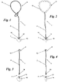
- the soap holder 1 of the present invention is suitable for supporting a soap bar 3, preferably by suspending it vertically, comprising a through-hole 3a.
- the through-hole 3a preferably does not pass through the shorter size but one of the two larger sizes, preferably the larger size of the others, or alternatively the second larger size.
- the soap holder 1 is preferably constrained to a support element 15, 20 , hereinafter described.
- the soap holder 1 and the support element 15, 20 together form a soap holder apparatus 100 .
- the soap holder 1 found substantially comprises:
- connection means 7 preferably comprise, and more preferably are, permanent magnets.
- the elongated body 2 may comprise a wire 2, made of steel, plastic or any other suitable material to ensure its flexibility.
- the elongated body 2 could be constituted in other preferable ways, for example a small plastic tube or other flexible material (not illustrated), in various configurations suitable for the purpose, or again in rigid, non-flexible material (such as, for example, an asti-form metal rod: in this solution, a joint, placed in the upper part of the body, could allow the movement of the rod in the desired directions).
- a small plastic tube or other flexible material not illustrated
- rigid, non-flexible material such as, for example, an asti-form metal rod: in this solution, a joint, placed in the upper part of the body, could allow the movement of the rod in the desired directions.
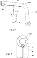
- the support element 15, 20 may comprise a tap 15, as illustrated in Fig. 5 , or a support 20 suitable to be placed on a plane ( Fig. 6 ) or a wall ( Fig. 7 ) for supporting the soap holder 1, if it is not considered useful to connect it directly to a tap 15.
- the support 20 may be provided, again as illustrated in Figures 6 and 7 , with at least one contact element 22 (e.g. a suction cup, common screws, double-sided adhesive tape) enabling the support 20 to be attached precisely to a plane or a wall.
- the attachment means 5 comprise a ring 9 made seamlessly with the cable 2, obtained by re-knotting the cable 2 on itself.
- the coupling means 5 comprise a ring 11 , preferably made of a plastic material, within which the cable 2 passes, or operatively connected to the cable 2.
- the coupling means 5 instead comprise at least one first threaded socket 13 suitable for being screwed into a corresponding first cavity 14 of the support element 15, 20.
- the attachment means 5 comprise a cavity 80 , preferably arranged on the lower surface of the sink, and a slider 81 , suitable for sliding within said cavity.
- the elongated body 2 is constrained to said slider.
- the connection means 7 comprise, in a known manner, at least a second threaded socket 16 apt to be screwed into a corresponding second cavity 17 of the holding elements 18, 18' .
- the soap holder 1 comprises, preferably, an elongated body 2 comprising an upper portion 50 and a lower portion 51 .
- the lower portion 51 is, preferably, in one piece with the holding element 18, 18', or integrally constrained thereto.
- the upper portion 50 comprises connection means 7 comprising an upper magnet 70
- the lower portion 51 comprises connection means 7 comprising a lower magnet 71 .
- the two magnets 70and 71 are preferably capable of being bound to each other, obviously by magnetic attraction.
- the upper magnet 70 and the lower magnet 71 are preferably housed within respective cavities 50a, 50b present in the upper and lower portions 50, 51.
- the upper magnet 70 and the lower magnet 71 when the device 1 is in a spare configuration, are facing outwards from the respective cavities 50a, 50b.
- the outwardly facing portions of the upper and lower magnets 70, 71 are preferably coated with powder coating.
- the elongated body 2 is preferably circular in cross-section. It also preferably has an average diameter between 0.5 mm and 1 cm and in particular between 5 mm and 1 cm.
- the attachment means 5 preferably comprise a support cable 60 constrained to the upper portion 50.
- the first hexagon socket 13 may be replaced by equivalent elements, which perform the functions of the coupling means 5.
- the coupling means 5 could be replaced by at least one hook (not illustrated) capable of being operatively inserted into a cavity (not illustrated) provided by the support element 15, 20.
- the attachment means 5 could be at least one magnetic element (not illustrated), also capable of being operatively coupled (in a manner known or within the reach of an average branch technician) to the support element 15, 20.
- soap holder 1 it is therefore possible to connect the soap holder 1 to a tap 15 or a surface or wall, and to use the soap 3 connected to it, before washing. Soiling of the washbasin, sink or other sanitary fixture is also prevented, as the wet soap drips briefly into the drainage basin and then dries in the air, without soiling external walls. Furthermore, soap 3 can be easily replaced, depending on the user's operational or even just aesthetic needs.
- the conceptual flexibility of the inventive soap holder 1 also allows it to be installed on a tap 15 which has been prepared for this purpose by means of the simple hole 14 in it: here, also, it is easy to screw and unscrew the soap holder 1 should one wish to insert it on the tap 15 or not, and it is just as easy to unscrew the holding element 18 should one wish to replace the soap 3 held by it in the soap holder 1.
- the use of the soap holder 1 of the present invention will also be open to persons with reduced manual abilities, for example handicapped persons or children, for whom the screwing of the various components in the traditional version would have been difficult to accomplish: in this case, the simple coupling of the soap holder 3 to the soap holder 1 allows the mutual magnetic coupling, in a simple, easy and reproducible manner in any configuration.
- the first lug 13 can be replaced by equivalent elements, which perform the functions of the attachment means 5.
- the attachment means 5 could be replaced by at least one hook (not illustrated) capable of being operatively inserted into a cavity (not illustrated) provided by the support element 15, 20.
- the attachment means 5 could be at least one magnetic element (not illustrated), also capable of being operatively coupled (in a manner known or within the reach of an average branch technician) to the support element 15, 20.
- the flexibility of the inventive soap holder 1 also allows it to be installed on a tap 15 prepared for the purpose by means of the simple hole 14 cut in it: here too, it is easy to screw and unscrew the soap holder 1 should one wish to insert it or not on the tap 15, and it is just as easy to unscrew the holding element 25 should one wish to replace the soap 3 supported by it in the soap holder.
Landscapes
- Health & Medical Sciences (AREA)
- Public Health (AREA)
- Detergent Compositions (AREA)
- Supports Or Holders For Household Use (AREA)
Applications Claiming Priority (1)
| Application Number | Priority Date | Filing Date | Title |
|---|---|---|---|
| IT202021000002267U IT202100002267U1 (it) | 2021-04-28 | 2021-04-28 | Portasaponetta flessibile |
Publications (1)
| Publication Number | Publication Date |
|---|---|
| EP4082413A1 true EP4082413A1 (fr) | 2022-11-02 |
Family
ID=81750684
Family Applications (1)
| Application Number | Title | Priority Date | Filing Date |
|---|---|---|---|
| EP22170197.2A Pending EP4082413A1 (fr) | 2021-04-28 | 2022-04-27 | Porte-savon |
Country Status (2)
| Country | Link |
|---|---|
| EP (1) | EP4082413A1 (fr) |
| IT (1) | IT202100002267U1 (fr) |
Citations (14)
| Publication number | Priority date | Publication date | Assignee | Title |
|---|---|---|---|---|
| FR387743A (fr) | 1908-03-03 | 1908-07-21 | Henri Schyrr | Savon avec trou central en vue de sa suspension |
| FR588556A (fr) | 1924-11-06 | 1925-05-12 | Savon et porte-savon combinés | |
| FR599967A (fr) | 1925-06-20 | 1926-01-27 | Ardanaz | Appareil porte-savon |
| FR754825A (fr) | 1933-04-27 | 1933-11-14 | Porte-savon et accessoire | |
| CH174319A (fr) | 1933-10-05 | 1935-01-15 | Scala G Pere | Appareil de suspension pour savons. |
| CH317014A (de) | 1953-10-14 | 1956-10-31 | Schnyder & Cie Ag Geb | Beweglicher Seifenträger |
| JPS569294U (fr) * | 1979-07-04 | 1981-01-27 | ||
| CN2047171U (zh) | 1989-01-24 | 1989-11-08 | 江晓伟 | 悬挂式肥皂架 |
| CN2061028U (zh) | 1990-01-13 | 1990-08-29 | 合肥工具厂 | 悬空肥皂架 |
| CN2267750Y (zh) | 1996-10-28 | 1997-11-19 | 王承志 | 一种皂挂 |
| DE19963449A1 (de) | 1999-12-28 | 2000-08-31 | Helga Frick | Halterung für Seife |
| DE19958433A1 (de) | 1999-12-03 | 2001-06-07 | Toni Becker | Seifenhalter |
| CN2482374Y (zh) | 2001-04-12 | 2002-03-20 | 王承刚 | 一种悬挂式肥皂架 |
| ITTO20111252A1 (it) * | 2011-12-31 | 2012-03-31 | Maria Teresa Zenone | Portasaponette flessibile |
-
2021
- 2021-04-28 IT IT202021000002267U patent/IT202100002267U1/it unknown
-
2022
- 2022-04-27 EP EP22170197.2A patent/EP4082413A1/fr active Pending
Patent Citations (14)
| Publication number | Priority date | Publication date | Assignee | Title |
|---|---|---|---|---|
| FR387743A (fr) | 1908-03-03 | 1908-07-21 | Henri Schyrr | Savon avec trou central en vue de sa suspension |
| FR588556A (fr) | 1924-11-06 | 1925-05-12 | Savon et porte-savon combinés | |
| FR599967A (fr) | 1925-06-20 | 1926-01-27 | Ardanaz | Appareil porte-savon |
| FR754825A (fr) | 1933-04-27 | 1933-11-14 | Porte-savon et accessoire | |
| CH174319A (fr) | 1933-10-05 | 1935-01-15 | Scala G Pere | Appareil de suspension pour savons. |
| CH317014A (de) | 1953-10-14 | 1956-10-31 | Schnyder & Cie Ag Geb | Beweglicher Seifenträger |
| JPS569294U (fr) * | 1979-07-04 | 1981-01-27 | ||
| CN2047171U (zh) | 1989-01-24 | 1989-11-08 | 江晓伟 | 悬挂式肥皂架 |
| CN2061028U (zh) | 1990-01-13 | 1990-08-29 | 合肥工具厂 | 悬空肥皂架 |
| CN2267750Y (zh) | 1996-10-28 | 1997-11-19 | 王承志 | 一种皂挂 |
| DE19958433A1 (de) | 1999-12-03 | 2001-06-07 | Toni Becker | Seifenhalter |
| DE19963449A1 (de) | 1999-12-28 | 2000-08-31 | Helga Frick | Halterung für Seife |
| CN2482374Y (zh) | 2001-04-12 | 2002-03-20 | 王承刚 | 一种悬挂式肥皂架 |
| ITTO20111252A1 (it) * | 2011-12-31 | 2012-03-31 | Maria Teresa Zenone | Portasaponette flessibile |
Also Published As
| Publication number | Publication date |
|---|---|
| IT202100002267U1 (it) | 2021-07-28 |
Similar Documents
| Publication | Publication Date | Title |
|---|---|---|
| US20150122961A1 (en) | Suspended Tool Holder and Modified Tool | |
| CN210994956U (zh) | 一种花洒固定装置 | |
| US12324548B2 (en) | Soap holder | |
| TWI840418B (zh) | 手持淋浴裝置 | |
| CA2813182C (fr) | Systeme d'installation d'un raccord d'accessoire de plomberie comportant un support et une garniture | |
| KR100438021B1 (ko) | 세면도구 걸이 | |
| AU2011231147B2 (en) | Waste fitting | |
| US9493935B2 (en) | Magnetic sink flange retainer and method | |
| WO2013098865A1 (fr) | Porte-savon flexible | |
| US20160038955A1 (en) | Shower spa attachment | |
| CN211973697U (zh) | 水槽、脸盆和浴缸 | |
| JP7738900B2 (ja) | 吸着磁石装置 | |
| JP2008136578A (ja) | コップ支持装置、石鹸支持装置及び支持装置 | |
| KR200306555Y1 (ko) | 칫솔대 | |
| KR200262369Y1 (ko) | 샤워기 | |
| JP4554050B2 (ja) | 仮設給水器具 | |
| CN213038732U (zh) | 卫浴装饰墙体以及适用于该墙体的卫浴配件 | |
| KR20210072329A (ko) | 탈부착식 샤워헤드 커버 | |
| JP3059258U (ja) | 洗面器用掛け具 | |
| SK500062019U1 (sk) | Magnetický úchytný systém | |
| KR20100009121U (ko) | 샤워기 자석 고정장치 | |
| KR20120127764A (ko) | 샤워기 부착구 | |
| JP5448764B2 (ja) | 水栓 | |
| JPH11229460A (ja) | 2ホール型の水栓取付構造 | |
| JP2008062007A (ja) | 転倒防止付家具 |
Legal Events
| Date | Code | Title | Description |
|---|---|---|---|
| PUAI | Public reference made under article 153(3) epc to a published international application that has entered the european phase |
Free format text: ORIGINAL CODE: 0009012 |
|
| STAA | Information on the status of an ep patent application or granted ep patent |
Free format text: STATUS: THE APPLICATION HAS BEEN PUBLISHED |
|
| AK | Designated contracting states |
Kind code of ref document: A1 Designated state(s): AL AT BE BG CH CY CZ DE DK EE ES FI FR GB GR HR HU IE IS IT LI LT LU LV MC MK MT NL NO PL PT RO RS SE SI SK SM TR |
|
| STAA | Information on the status of an ep patent application or granted ep patent |
Free format text: STATUS: REQUEST FOR EXAMINATION WAS MADE |
|
| 17P | Request for examination filed |
Effective date: 20230428 |
|
| RBV | Designated contracting states (corrected) |
Designated state(s): AL AT BE BG CH CY CZ DE DK EE ES FI FR GB GR HR HU IE IS IT LI LT LU LV MC MK MT NL NO PL PT RO RS SE SI SK SM TR |