EP4082452B1 - Chirurgische schneidführung - Google Patents
Chirurgische schneidführung Download PDFInfo
- Publication number
- EP4082452B1 EP4082452B1 EP21171090.0A EP21171090A EP4082452B1 EP 4082452 B1 EP4082452 B1 EP 4082452B1 EP 21171090 A EP21171090 A EP 21171090A EP 4082452 B1 EP4082452 B1 EP 4082452B1
- Authority
- EP
- European Patent Office
- Prior art keywords
- wall portion
- cutting guide
- cutting
- body segment
- surgical cutting
- Prior art date
- Legal status (The legal status is an assumption and is not a legal conclusion. Google has not performed a legal analysis and makes no representation as to the accuracy of the status listed.)
- Active
Links
Images



Classifications
-
- A—HUMAN NECESSITIES
- A61—MEDICAL OR VETERINARY SCIENCE; HYGIENE
- A61B—DIAGNOSIS; SURGERY; IDENTIFICATION
- A61B17/00—Surgical instruments, devices or methods
- A61B17/14—Surgical saws
- A61B17/15—Guides therefor
-
- A—HUMAN NECESSITIES
- A61—MEDICAL OR VETERINARY SCIENCE; HYGIENE
- A61B—DIAGNOSIS; SURGERY; IDENTIFICATION
- A61B17/00—Surgical instruments, devices or methods
- A61B17/14—Surgical saws
- A61B17/15—Guides therefor
- A61B17/154—Guides therefor for preparing bone for knee prosthesis
- A61B17/155—Cutting femur
-
- A—HUMAN NECESSITIES
- A61—MEDICAL OR VETERINARY SCIENCE; HYGIENE
- A61B—DIAGNOSIS; SURGERY; IDENTIFICATION
- A61B17/00—Surgical instruments, devices or methods
- A61B2017/00526—Methods of manufacturing
Definitions
- the invention relates to a surgical cutting guide according to claim 1
- Surgical cutting guides are used during orthopedic surgical procedures to assist the surgeon in executing proper bone cuts.
- a surgeon performing a total knee arthroplasty can make one or several cuts on the distal end of the femur, such as to properly fit a prosthetic femoral component.
- the surgical cutting guide allows executing more accurate cuts by guiding the used surgical cutting instrument.
- EP 2 774 554 A1 discloses a surgical cutting guide having a cutting slot formed between a first cutting guide surface and a second cutting guide surface. Said cutting guide surfaces are opposite each other in transverse direction of the cutting slot. The cutting slot extends in longitudinal direction between two opposing end stop surfaces. Said end stop surfaces a formed by outer surfaces of cylindrical bushings. The outer surfaces of said cylindrical bushings are convex with respect to the transverse direction of the cutting slot and flat with respect to a height direction of the cutting slot.
- WO 2015/112566 A1 discloses a surgical cutting guide with a convex cutting guide surface and with end stop surfaces. Said end stop surfaces are concave with respect to the transverse direction of the cutting slot and flat with respect to the height direction of the cutting slot.
- EP 3 649 968 A1 discloses a surgical cutting guide comprising cutting guide surfaces with concave recesses for reduced frictional contact with the cutting instrument.
- US 2013/0325017 A1 discloses a surgical cutting guide including a body with a cutting slot configured to receive a surgical cutting instrument.
- the cutting slot is formed between two opposing cutting guide surfaces and extends longitudinally between a first end stop surface and an opposing second end stop surface.
- the opposing end stop surfaces each have a flat surface contour.
- the first end stop surface has a first convex surface contour and/or the second end stop surface has a second convex surface contour.
- the present inventors have recognized that providing at least one of the two end stop surfaces with a convex surface contour helps to avoid friction and friction-induced wear between the surgical cutting instrument and the first cutting slot. Moreover, providing at least one of the end stop surfaces with a convex surface contour enables a larger longitudinal inclination angle of the surgical cutting instrument within the first cutting slot in comparison to a cutting slot having the same length, but flat end stop surfaces. These benefits result in an improved guiding of the cutting instrument.
- the first convex surface contour and/or the second convex surface contour are curved in vertical direction of the first cutting slot.
- the surgical cutting guide is for use during a surgical procedure.
- the at least one first cutting slot is configured to receive a surgical cutting instrument.
- the first cutting guide surface and the second cutting guide surface each can be sized, shaped, or otherwise configured to accommodate the surgical cutting instrument placed against it.
- the first cutting guide surface and the second cutting guide surface each have a flat surface contour.
- the first cutting guide surface and the second cutting guide surface oppose each other in transverse direction of the first cutting slot.
- the first cutting guide surface and the second cutting guide surface are parallel to each other.
- the body is formed integrally, i.e. as a single piece of material.
- the body can comprise a plurality of separate body parts, which are fixedly or releasably joined together.
- the body can be manufactured of a metal material and/or a plastic material.
- the first convex surface contour and/or the second convex surface contour is formed by at least one radius, the radius being between 10 mm and 30 mm. In one embodiment, the radius is between 15 mm and 25 mm. In one embodiment, the radius is 18 mm.
- the present inventors have recognized that a radius between 10 mm and 30 mm has the benefit of providing reduced friction and friction-induced wear for many different common types and/or sizes of surgical cutting instruments. In this context it was found that a radius between 15 mm and 25 mm is particularly advantageous for surgical cutting instruments used during total knee arthroplasty.
- the first convex surface contour and the second convex surface contour have the same radius. In other embodiments, the first convex surface contour is formed by a first radius and the second convex surface contour is formed by a different second radius.
- the first convex surface contour and/or the second convex surface contour is defined by a plurality of tangential radii. This allows an improved adaption of the first convex surface contour and/or the second convex surface contour to a specific cutting procedure and/or a specific surgical cutting instrument to be used.
- the radii are within the intervals mentioned in the context of the previous embodiment.
- the first cutting guide surface is formed on an inner side of a first wall portion, included in or coupled to the body, and the second cutting guide surface is formed on an opposing inner side of a second wall portion, included in or coupled to the body.
- the inner side of the first wall portion and the inner side of the second wall portion face each other in transverse direction of the first cutting slot.
- the first wall portion and the second wall portion form an integral body segment of the body.
- the first wall portion and the second wall portion are formed as separate parts being fixedly or releasably joined together.
- the first end stop surface is formed on an inner side of a third wall portion, included in or coupled to the body, and the second end stop surface is formed on an inner side of a fourth wall portion, included in or coupled to the body, wherein the third wall portion and the fourth wall portion each extend in transverse direction of the first cutting slot between the first wall portion and the second wall portion.
- the inner side of the third wall portion and the inner side of the fourth wall portion face each other in longitudinal direction of the first cutting slot.
- the first wall portion, the second wall portion, the third wall portion and the fourth wall portion form an integral body segment of the body.
- at least one of said wall portions is formed as a separate body part and fixedly or releasably joined together with at least one other of said wall portions.
- the first wall portion has at least one first surface reduction recess extending between the inner side and an opposing outer side of the first wall portion and/or the second wall portion has at least one second surface reduction recess extending between the inner side and an opposing outer side of the second wall portion.
- the first surface reduction recess causes a reduction of the first cutting guide surface.
- the second reduction recess causes a reduction of the second cutting guide surface.
- the reduction of the first cutting guide surface and/or second cutting guide surface leads to a further reduction of friction and friction-induced wear between the surgical cutting instrument and the first cutting slot.
- the first surface reduction recess extends into the first wall portion in transverse direction of the first cutting slot.
- the first surface reduction recess is formed as a pocket countersunk into the inner side of the first wall portion. In another embodiment, the first surface reduction recess is formed as an aperture within the first wall portion. The same holds analogously with respect to the second surface reduction recess.
- the first surface reduction recess forms a first aperture and/or the second surface reduction recess forms a second aperture.
- the first aperture extends from the inner side to the outer side of the first wall portion in transverse direction of the first cutting slot.
- the second aperture extends from the inner side to the outer side of the second wall portion in transverse direction of the first cutting slot.
- the first wall portion has a plurality of surface reduction recesses defining a first recess pattern and the second wall portion has a plurality of second surface reduction recesses defining a different second recess pattern.
- the different recess patterns ensure that the surgical cutting instrument is in contact with and guided by at least one of the first cutting guide surface or the second cutting guide surface. In contrast to this, equal recess patterns can lead to opposite areas of the surgical cutting instrument having no contact at the same time. This can be disadvantageous under certain circumstances.
- at least one of the first and second recess patterns is formed as aperture pattern having a plurality of surface reduction apertures.
- the first cutting slot body segment - in a viewing direction normal to the outer side of the first wall portion - has an outer contour comprising a flat inferior contour portion and a convex superior contour portion.
- the flat inferior contour portion ensures that the first cutting slot body segment can be placed flat and securely positioned on the bone to be cut.
- the convex superior contour portion allows for an improved handling of the surgical cutting guide by the operating surgeon. In addition, material and thus weight can be saved. This allows for an even easier handling.
- the convex superior contour portion causes a variable height of the first cutting slot body segment along the longitudinal direction of the first cutting slot. In the area of the third and the fourth wall portion - and therefore at the ends of the first cutting slot - the height of the first cutting slot body segment is comparatively low. The height is comparatively high in a longitudinally central area of the first cutting slot.
- the body comprises a bone engagement body segment having an inferior bone engagement surface, the bone engagement body segment and the first cutting slot body segment being spaced apart from each other to form at least one bone viewing aperture.
- the at least one bone viewing aperture allows for an improved visibility of the target bone below the surgical cutting guide. This improved visibility helps the operating surgeon to align and position the surgical cutting guide on the bone to be cut.
- the at least one bone viewing aperture allows for a further reduction of material and thus less weight. This leads to further reduced manufacturing costs and improved manual handling.
- the inferior bone engagement surface is configured to engage with the bone to be cut.
- the bone engagement body segment comprises at least one through-hole configured for receiving a fixation element for fixing the bone engagement body segment to the bone to be cut.
- the bone engagement body segment and the first cutting slot body segment form an integral portion of the body.
- the bone engagement body segment and the first cutting slot body segment are formed as separate parts of the body.
- the bone engagement body segment and the first cutting slot body segment can be fixedly or releasably joined together.
- the bone engagement body segment and the first cutting slot body segment are spaced apart from each other in transverse direction of the first cutting slot.
- the bone engagement body segment has a block-like shape and the first cutting slot body segment has a ledge-like form.
- the first cutting slot body segment and the bone engagement body segment are connected by means of a strut body segment having at least a first strut and a second strut spaced apart from each other in longitudinal direction of the first cutting slot to form the at least one bone viewing aperture.
- the first strut and the second strut each are elongated in transverse direction of the first cutting slot.
- a first end of the first strut is connected to the bone engagement body segment and a second end of the first strut is connected to the first cutting slot body segment.
- This embodiment helps to further reduce the weight of the body and allows for a comparatively large bone viewing aperture.
- the first cutting slot body segment, the bone engagement body segment and the strut body segment form an integral body portion of the body.
- at least one of said body segments is formed as separate body part and fixedly or releasably joined together with at least one other of said body segments.
- a surgical cutting guide 1 is provided for use in a surgical procedure.
- the surgical cutting guide 1 can be used to prepare the distal end of a femur B ( fig. 4 ) for a total knee arthroplasty procedure.
- a surgeon performing such a total knee arthroplasty can make several cuts on the distal end of the femur B, in order to properly fit a prosthetic femoral component.
- the surgical cutting guide 1 is configured to guide an according surgical cutting instrument, such as a saw or the like. Guiding the surgical cutting instrument by means of the surgical cutting guide 1 allows for an improved accuracy of the delivered cuts.
- the first cutting slot 3 is configured to receive the surgical cutting instrument in its vertical direction. Once inserted into the first cutting slot 3, the surgical cutting instrument fits snugly between the first cutting guide surface 4 and the second cutting guide surface 5 in transverse direction Y.
- the first cutting guide surface 4 and the second cutting guide surface 5 guide the surgical cutting instrument along the longitudinal direction X and vertically, wherein the first end stop surface 6 and the second end stop surface 7 prevent the surgical cutting instrument from escaping the first cutting slot 3.
- the surgical cutting instrument moves relatively to the first and second cutting guide surfaces 4, 5 and the first and second end stop surfaces 6, 7. This relative movement causes friction as well as friction-induced wear.
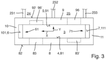
- both end stop surfaces 6, 7 have a convex surface contour.
- the first end stop surface 6 has a first convex surface contour 61 and the second end stop surface 7 has a second convex surface contour 71. Due to their convex shape, the first end stop surface 6 and the second end stop surface 7 are each curved along the vertical direction of the first cutting slot 3. In other words the first end stop surface 6 and the second end stop surface 7 each curve inwards the first cutting slot 3 with respect to the longitudinal direction X.
- Fig. 6 illustrates further benefits of the first and second convex surface contours 61, 71.
- two exemplary configurations are schematically superimposed:
- an exemplary surgical cutting instrument C is inserted into the first cutting slot 3 and inclined along the longitudinal direction X. Because of said inclination, opposing edges of the surgical cutting instrument C contact the first convex surface contour 61 and the second convex surface contour 72, respectively.
- the surgical cutting instrument is inserted in a cutting slot 3' having opposing flat end stop surfaces 6', 7'.
- the surgical cutting instrument is referenced as C'.
- a comparison of the first configuration and the second configuration illustrates that providing the end stop surfaces with convex surface contours allows for a greater inclination angle in comparison to a cutting slot having the same length and flat end stop surfaces.
- the convex surface contours allow for a reduction of the cutting slot length by approximately 10 % in comparison to flat end stop surfaces.
- the present inventors have further recognized that the convex surface contours 61, 71 help to stabilize the surgical cutting instrument C during cutting in its inclined orientation.
- the convex surface contours 61, 71 help to decrease the contact load on the opposing edges of the surgical cutting instrument C. Decreasing the contact load leads to the already mentioned reduction of friction and friction-induced wear. In contrast to this, inclining the surgical cutting instrument C' between the flat end stop surfaces 6', 7' leads to a sharp point contact, which can result in increased friction and wear.
- the first convex surface contour 61 is formed by a radius R, the radius being 18 mm. In other embodiments, the radius can range between 10 mm and 30 mm. The same may apply with respect to the second convex surface contour 71. However, in the embodiment shown, the second convex surface contour 71 is defined by a plurality of tangential radii R1, R2, R3. Said radii R1, R2, R3 range between 10 mm and 30 mm. In other embodiments, the first convex surface contour 61 and the second convex surface contour 71 are formed by one and the same radius.
- the first end stop surface 6 is formed on an inner side 101 of a third wall portion 10.
- the second end stop surface 7 is formed on an inner side 111 of a fourth wall portion 11.
- the third wall portion 10 and the fourth wall portion 11 oppose each other in longitudinal direction X of the first cutting slot 3.
- the third wall portion 10 and the fourth wall portion 11 each extend in transverse direction Y of the first cutting slot 3 between the first wall portion 8 and the second wall portion 9. Both, the third wall portion 10 and the fourth wall portion 11, can be included in or coupled to the body 2, which will be described in more detail below.
- the first wall portion 8 has a plurality of surface reduction apertures 83, 84, 85, 86 defining a first aperture pattern within the first wall portion 8.
- Said surface apertures recesses 83, 84, 85, 86 can also be denoted as windows, breakthroughs or the like.
- the second wall portion 9 comprises a plurality of surface reduction apertures 93, 94, 95, 96, 97 defining a second aperture pattern.
- the apertures 93, 94, 95, 96, 97 form windows and/or breakthroughs within the second wall portion 9.
- only one of the first and the second wall portions 8, 9 comprises one or more apertures.
- the apertures 83, 84, 85, 86 within the first wall portion 8 serve to reduce the amount of contact between the surgical cutting instrument and the first cutting guide surface 4.
- said apertures 83, 84, 85, 86 reduce the first cutting guide surface 4 in comparison to an embodiment that does not comprise apertures within the first wall portion.
- providing said apertures 83 to 86 and 93 to 97 helps to reduce the overall weight of the surgical cutting guide 1, which improves manual handling during the surgical procedure.
- the body 2 comprises, in the embodiment shown, a bone engagement body segment 22, which is configured for engagement with the bone to be cut, in this case the distal femur B.
- the bone engagement body segment 22 comprises an inferior bone engagement surface 221 (see fig. 1 ), which opposes a superior surface 222.
- the inferior bone engagement surface 221 and the superior surface 222 oppose each other in vertical direction of the first cutting slot 3.
- the inferior bone engagement surface 221 can comprise a post, bolt or other fixation element for releasable fixation of the surgical cutting guide 1 to the target bone.
- the bone engagement body segment 22 comprises a plurality of through-holes 223 which extend between the superior surface 222 and the inferior bone engagement surface 221. Said through-holes 223 are configured to receive a fixation element or the like.
- the bone engagement body segment 22, in the embodiment shown, is formed as a single and/or unitary piece of material.
- the first cutting slot body segment 21 and the bone engagement body segment 22 are spaced apart from each other to form at least one bone viewing aperture 24, 25.
- two bone viewing apertures 24, 25 are formed, which can be denoted as first bone viewing aperture 24 and second bone viewing aperture 25.
- the bone engagement body segment 22 and the first cutting slot body segment 21 are spaced apart along the transverse direction Y of the first cutting slot 3.
- the bone viewing apertures 24, 25 allow for an improved visibility of the target bone and thus for an improved positioning and alignment of the surgical cutting guide 1.
- providing the bone viewing apertures 24, 25 further helps to reduce the overall weight of the surgical cutting guide 1.
- first cutting slot body segment 21 and the bone engagement body segment 22 are connected by means of a strut body segment 23 of the body 2.
- the strut body segment 23 in the embodiment shown, comprises a first strut 231, a second strut 232 and a third strut 233 which are spaced apart from each other in longitudinal direction X of the first cutting slot 3.
- the strut body segment 23 comprises only a single, two or more than three struts.
- the first strut 231, the second strut 232 and the third strut 233 each have an elongated and/or slender shape.
- the first strut element 231, the second strut element 232 and the third strut element 233 each extend in transverse direction Y of the first cutting slot 3, wherein a first end of each of the struts is connected to the bone engagement body segment 22 and a second end of each strut is connected to the first cutting slot body segment 21.
- the first bone viewing aperture 24 extends between the first strut 231 and the second strut 232 in longitudinal direction X and between the first cutting slot body segment 21 and the bone engagement body segment 22 in transverse direction Y of the first cutting slot 3.
- the second bone viewing aperture 25 extends between the second strut 232 and the third strut 233 in longitudinal direction X and between the first cutting slot body segment 21 and the bone engagement body segment 22 in transverse direction Y of the first cutting slot 3.
- the first cutting slot body segment 21 has an outer contour 211, 212, 213, 214 (see fig. 5 ), which comprises a convex superior contour portion 211, a flat inferior contour portion 213 and opposing outer end contour portions 212, 214.
- the convex superior contour portion 211 and the flat inferior contour portion 213 oppose each other in vertical direction of the first cutting slot 3.
- the outer end contour portions 212, 214 oppose each other in longitudinal direction X of the first cutting slot 3.
- the outer end contour portions 212, 214 each have a convex shape.
- the flat inferior contour portion 213 allows for an improved alignment and positioning of the surgical cutting guide 1 on the target bone.
- the convex superior contour portion 211 helps to reduce the bulkiness of the body.
- the convex shape of the superior contour portion 211 as well as the convex shape of the outer end contour portions 212, 214 causes less impairment and/or injury of body tissue during the surgical procedure in comparison to a flat contour shape.
- the body 2 comprises a second cutting slot body segment 21'. In other embodiments, only a single cutting slot body segment or more than two cutting slot body segments are provided.
- the second cutting slot body segment 21' opposes the first cutting slot body segment 21 in transverse direction Y and is arranged on an opposing side of the bone engagement body segment 22.
- the second cutting slot body segment 21' is, in the embodiment shown, slightly longer than the first cutting slot body segment 21. Apart from this, the second cutting slot body segment 21' is identical. Hence, what has been disclosed with regard to the first cutting slot body segment 21 also applies mutatis mutandis with regard to the second cutting slot body segment 21'. Therefore, further explanations in regard of the second cutting slot body segment 21' are not necessary.
- Fig. 8 shows a surgical cutting guide 500 known from prior art.
- the surgical cutting guide 500 has a rather bulky shape S', which can cause a rather high weight and thus, high material cost and suboptimal handling during the surgical procedure.
- the surgical cutting guide 1 has a reduced bulkiness, which allows for a reduced weight, reduced material costs, improved handling and improved bone visibility during the surgical procedure.
Landscapes
- Health & Medical Sciences (AREA)
- Surgery (AREA)
- Life Sciences & Earth Sciences (AREA)
- Biomedical Technology (AREA)
- Public Health (AREA)
- Oral & Maxillofacial Surgery (AREA)
- Nuclear Medicine, Radiotherapy & Molecular Imaging (AREA)
- Veterinary Medicine (AREA)
- Dentistry (AREA)
- Engineering & Computer Science (AREA)
- General Health & Medical Sciences (AREA)
- Heart & Thoracic Surgery (AREA)
- Medical Informatics (AREA)
- Molecular Biology (AREA)
- Animal Behavior & Ethology (AREA)
- Orthopedic Medicine & Surgery (AREA)
- Physical Education & Sports Medicine (AREA)
- Transplantation (AREA)
- Surgical Instruments (AREA)
- Laser Surgery Devices (AREA)
Claims (13)
- Chirurgische Schneidführung (1), umfassend:einen Körper (2) mit mindestens einem ersten Schneidschlitz (3),wobei der erste Schneidschlitz (3) zwischen einer ersten Schneidführungsfläche (4) und einer gegenüberliegenden zweiten Schneidführungsfläche (5) ausgebildet ist,wobei sich der erste Schneidschlitz (3) in Längsrichtung zwischen einer ersten Endanschlagfläche (6) und einer gegenüberliegenden zweiten Endanschlagfläche (7) erstreckt,und wobei die erste Endanschlagfläche (6) eine erste konvexe Oberflächenkontur (61) aufweist und/oder die zweite Endanschlagfläche (7) eine zweite konvexe Oberflächenkontur (71) aufweist,dadurch gekennzeichnet, dass die erste konvexe Oberflächenkontur (61) und/oder die zweite konvexe Oberflächenkontur (71) durch mindestens einen Radius (R) gebildet ist, wobei der Radius (R) zwischen 10 mm und 30 mm beträgt.
- Chirurgische Schneidführung (1) nach Anspruch 1, dadurch gekennzeichnet, dass der Radius (R) zwischen 15 mm und 25 mm beträgt.
- Chirurgische Schneidführung (1) nach Anspruch 1 oder 2, dadurch gekennzeichnet, dass der Radius (R) 18 mm beträgt.
- Chirurgische Schneidführung (1) nach einem der vorhergehenden Ansprüche, dadurch gekennzeichnet, dass die erste konvexe Oberflächenkontur (61) und/oder die zweite konvexe Oberflächenkontur (71) durch eine Vielzahl von Tangentialradien (R1, R2, R3) definiert ist.
- Chirurgische Schneidführung (1) nach einem der vorhergehenden Ansprüche, dadurch gekennzeichnet, dass die erste Schneidführungsfläche (4) an einer Innenseite (81) eines ersten Wandabschnitts (8) ausgebildet ist, der in dem Körper (2) enthalten oder an diesen gekoppelt ist, und die zweite Schneidführungsfläche (5) an einer gegenüberliegenden Innenseite (91) eines zweiten Wandabschnitts (9) ausgebildet ist, der in dem Körper (2) enthalten oder an diesen gekoppelt ist.
- Chirurgische Schneidführung (1) nach Anspruch 5, dadurch gekennzeichnet, dass die erste Endanschlagfläche (6) an einer Innenseite (101) eines dritten Wandabschnitts (10) ausgebildet ist, der in dem Körper (2) enthalten oder an diesen gekoppelt ist, und die zweite Endanschlagfläche (7) an einer Innenseite (111) eines vierten Wandabschnitts (11) ausgebildet ist, der in dem Körper (2) enthalten oder an diesen gekoppelt ist, wobei sich der dritte Wandabschnitt (10) und der vierte Wandabschnitt (11) jeweils in einer Querrichtung (Y) des ersten Schneidschlitzes (3) zwischen dem ersten Wandabschnitt (8) und dem zweiten Wandabschnitt (9) erstrecken.
- Chirurgische Schneidführung (1) nach Anspruch 5 oder 6, dadurch gekennzeichnet, dass der erste Wandabschnitt (8) mindestens eine erste Oberflächenreduzierungsaussparung (83') aufweist, die sich zwischen der Innenseite (81) und einer gegenüberliegenden Außenseite (82) des ersten Wandabschnitts (8) erstreckt, und/oder der zweite Wandabschnitt (9) mindestens eine zweite Oberflächenreduzierungsaussparung (96') aufweist, die sich zwischen der Innenseite (91) und einer gegenüberliegenden Außenseite (92) des zweiten Wandabschnitts (9) erstreckt.
- Chirurgische Schneidführung (1) nach Anspruch 7, dadurch gekennzeichnet, dass die erste Oberflächenreduzierungsaussparung (83') eine erste Öffnung (83) bildet und/oder die zweite Oberflächenreduzierungsaussparung (96') eine zweite Öffnung (96) bildet.
- Chirurgische Schneidführung (1) nach Anspruch 7 oder 8, dadurch gekennzeichnet, dass der erste Wandabschnitt (8) eine Vielzahl von Oberflächenreduzierungsaussparungen (83, 84, 85, 86) aufweist, die ein erstes Aussparungsmuster definieren, und der zweite Wandabschnitt (9) eine Vielzahl von zweiten Oberflächenreduzierungsaussparungen (93, 94, 95, 96, 97) aufweist, die ein unterschiedliches zweites Aussparungsmuster definieren.
- Chirurgische Schneidführung (1) nach Anspruch 6 oder nach einem der Ansprüche 7 bis 9, wenn sie von Anspruch 6 abhängen, dadurch gekennzeichnet, dass der erste Wandabschnitt (8), der zweite Wandabschnitt (9), der dritte Wandabschnitt (10) und der vierte Wandabschnitt (11) ein integrales erstes Schneidschlitzkörpersegment (21) des Körpers (2) bilden.
- Chirurgische Schneidführung (1) nach Anspruch 10, dadurch gekennzeichnet, dass das erste Schneidschlitzkörpersegment (21) - in einer orthogonal zu der Außenseite (82) des ersten Wandabschnitts (8) verlaufenden Blickrichtung - eine Außenkontur (211, 212, 213, 214) aufweist, die einen flachen unteren Konturabschnitt (213) und einen konvexen oberen Konturabschnitt (211) umfasst.
- Chirurgische Schneidführung (1) nach Anspruch 10 oder 11, dadurch gekennzeichnet, dass der Körper (2) ein Knocheneingriffskörpersegment (22) mit einer unteren Knocheneingriffsfläche (221) umfasst, wobei das Knocheneingriffskörpersegment (22) und das erste Schneidschlitzkörpersegment (21) voneinander beabstandet sind, um mindestens eine Knochenbetrachtungsöffnung (24, 25) zu bilden.
- Chirurgische Schneidführung (1) nach Anspruch 12, dadurch gekennzeichnet, dass das erste Schneidschlitzkörpersegment (21) und das Knocheneingriffskörpersegment (22) mittels eines Strebenkörpersegments (23) verbunden sind, das mindestens eine erste Strebe (231) und eine zweite Strebe (232) aufweist, die in Längsrichtung (X) des ersten Schneidschlitzes (3) voneinander beabstandet sind, um die mindestens eine Knochenbetrachtungsöffnung (24, 25) zu bilden.
Priority Applications (6)
| Application Number | Priority Date | Filing Date | Title |
|---|---|---|---|
| EP21171090.0A EP4082452B1 (de) | 2021-04-29 | 2021-04-29 | Chirurgische schneidführung |
| JP2023566727A JP2024519476A (ja) | 2021-04-29 | 2022-04-29 | 外科用切断ガイド |
| PCT/EP2022/061444 WO2022229369A1 (en) | 2021-04-29 | 2022-04-29 | Surgical cutting guide |
| EP22726438.9A EP4329639A1 (de) | 2021-04-29 | 2022-04-29 | Chirurgische schneidführung |
| US18/555,788 US12558104B2 (en) | 2021-04-29 | 2022-04-29 | Surgical cutting guide |
| AU2022263627A AU2022263627A1 (en) | 2021-04-29 | 2022-04-29 | Surgical cutting guide |
Applications Claiming Priority (1)
| Application Number | Priority Date | Filing Date | Title |
|---|---|---|---|
| EP21171090.0A EP4082452B1 (de) | 2021-04-29 | 2021-04-29 | Chirurgische schneidführung |
Publications (2)
| Publication Number | Publication Date |
|---|---|
| EP4082452A1 EP4082452A1 (de) | 2022-11-02 |
| EP4082452B1 true EP4082452B1 (de) | 2025-01-15 |
Family
ID=75746182
Family Applications (2)
| Application Number | Title | Priority Date | Filing Date |
|---|---|---|---|
| EP21171090.0A Active EP4082452B1 (de) | 2021-04-29 | 2021-04-29 | Chirurgische schneidführung |
| EP22726438.9A Pending EP4329639A1 (de) | 2021-04-29 | 2022-04-29 | Chirurgische schneidführung |
Family Applications After (1)
| Application Number | Title | Priority Date | Filing Date |
|---|---|---|---|
| EP22726438.9A Pending EP4329639A1 (de) | 2021-04-29 | 2022-04-29 | Chirurgische schneidführung |
Country Status (5)
| Country | Link |
|---|---|
| US (1) | US12558104B2 (de) |
| EP (2) | EP4082452B1 (de) |
| JP (1) | JP2024519476A (de) |
| AU (1) | AU2022263627A1 (de) |
| WO (1) | WO2022229369A1 (de) |
Families Citing this family (2)
| Publication number | Priority date | Publication date | Assignee | Title |
|---|---|---|---|---|
| USD915588S1 (en) * | 2019-04-09 | 2021-04-06 | Paragon 28, Inc. | Cutting guide |
| USD904609S1 (en) | 2019-04-09 | 2020-12-08 | Paragon 28, Inc. | Cutting guide |
Family Cites Families (5)
| Publication number | Priority date | Publication date | Assignee | Title |
|---|---|---|---|---|
| DE102005026789A1 (de) | 2005-06-10 | 2006-12-21 | Aesculap Ag & Co. Kg | Chirurgische Sägeschablone |
| US20130325017A1 (en) | 2012-05-29 | 2013-12-05 | Zimmer, Inc. | Surgical cutting guide and method |
| US10022130B2 (en) * | 2013-03-05 | 2018-07-17 | Depuy Ireland Unlimited Company | Polymer 4-in-1 femoral cutting block |
| US10588639B2 (en) * | 2014-01-23 | 2020-03-17 | Conformis, Inc. | Spring-fit surgical guides |
| US11446041B2 (en) * | 2018-11-07 | 2022-09-20 | Cilag Gmbh International | Knee chamfer block guide with 3D printed undercut saw slot |
-
2021
- 2021-04-29 EP EP21171090.0A patent/EP4082452B1/de active Active
-
2022
- 2022-04-29 AU AU2022263627A patent/AU2022263627A1/en active Pending
- 2022-04-29 EP EP22726438.9A patent/EP4329639A1/de active Pending
- 2022-04-29 WO PCT/EP2022/061444 patent/WO2022229369A1/en not_active Ceased
- 2022-04-29 JP JP2023566727A patent/JP2024519476A/ja active Pending
- 2022-04-29 US US18/555,788 patent/US12558104B2/en active Active
Also Published As
| Publication number | Publication date |
|---|---|
| EP4329639A1 (de) | 2024-03-06 |
| JP2024519476A (ja) | 2024-05-14 |
| US20240197337A1 (en) | 2024-06-20 |
| US12558104B2 (en) | 2026-02-24 |
| WO2022229369A1 (en) | 2022-11-03 |
| AU2022263627A1 (en) | 2023-10-26 |
| EP4082452A1 (de) | 2022-11-02 |
Similar Documents
| Publication | Publication Date | Title |
|---|---|---|
| JP2609411B2 (ja) | 大腿骨切断ガイド | |
| US7452381B2 (en) | Radial head replacement system | |
| EP2623044B1 (de) | Chirurgischer Schnittblock | |
| CA1323730C (en) | Prosthetic knee joint with improved patellar component tracking | |
| US5041117A (en) | Elbow arthroplasty instrumentation and surgical procedure | |
| EP4082452B1 (de) | Chirurgische schneidführung | |
| US5405349A (en) | Cutting jig for posterior stabilized knee prosthesis | |
| US7628794B2 (en) | Prosthetic revision knee system | |
| US7938862B2 (en) | Artificial joint and a joint part intended for this purpose | |
| US9522007B2 (en) | Orthopedic saw blade | |
| KR20140061466A (ko) | 관절 인공 삽입물을 위한 외형 윤곽을 형성하는 절단 가이드 | |
| WO1999038448A1 (en) | A fixation device for a bone fracture | |
| RU2677917C2 (ru) | Система для использования в операции на коленном суставе | |
| EP2953583B1 (de) | Konische wadenbeinverstärkung | |
| EP2777620A1 (de) | Orthopädische Knieprothese | |
| EP2574290B1 (de) | Patellaresektionsanordnung | |
| EP1052946A1 (de) | Vorrichtung zur fixierung von knochenbrüchen | |
| KR20170134473A (ko) | 세라믹으로 제조되는 톱날 안내부를 갖는 플라스틱으로 제조되는 커팅 블록 | |
| ES2361486T3 (es) | Plantilla de sierra para realizar una resección ósea. | |
| US12208013B2 (en) | Implant systems for repair of a humeral head | |
| US10188404B2 (en) | Orthopedic instrumentation | |
| US20240293113A1 (en) | Retractor device | |
| US20180132867A1 (en) | System for orthopedic implantation preparation | |
| WO2015123270A1 (en) | Femoral and tibial cutting blocks | |
| US6190418B1 (en) | Endoprosthesis with anchoring shaft |
Legal Events
| Date | Code | Title | Description |
|---|---|---|---|
| PUAI | Public reference made under article 153(3) epc to a published international application that has entered the european phase |
Free format text: ORIGINAL CODE: 0009012 |
|
| STAA | Information on the status of an ep patent application or granted ep patent |
Free format text: STATUS: THE APPLICATION HAS BEEN PUBLISHED |
|
| AK | Designated contracting states |
Kind code of ref document: A1 Designated state(s): AL AT BE BG CH CY CZ DE DK EE ES FI FR GB GR HR HU IE IS IT LI LT LU LV MC MK MT NL NO PL PT RO RS SE SI SK SM TR |
|
| RAP1 | Party data changed (applicant data changed or rights of an application transferred) |
Owner name: AESCULAP AG |
|
| STAA | Information on the status of an ep patent application or granted ep patent |
Free format text: STATUS: REQUEST FOR EXAMINATION WAS MADE |
|
| 17P | Request for examination filed |
Effective date: 20230428 |
|
| RBV | Designated contracting states (corrected) |
Designated state(s): AL AT BE BG CH CY CZ DE DK EE ES FI FR GB GR HR HU IE IS IT LI LT LU LV MC MK MT NL NO PL PT RO RS SE SI SK SM TR |
|
| GRAP | Despatch of communication of intention to grant a patent |
Free format text: ORIGINAL CODE: EPIDOSNIGR1 |
|
| STAA | Information on the status of an ep patent application or granted ep patent |
Free format text: STATUS: GRANT OF PATENT IS INTENDED |
|
| INTG | Intention to grant announced |
Effective date: 20241030 |
|
| GRAS | Grant fee paid |
Free format text: ORIGINAL CODE: EPIDOSNIGR3 |
|
| GRAA | (expected) grant |
Free format text: ORIGINAL CODE: 0009210 |
|
| STAA | Information on the status of an ep patent application or granted ep patent |
Free format text: STATUS: THE PATENT HAS BEEN GRANTED |
|
| AK | Designated contracting states |
Kind code of ref document: B1 Designated state(s): AL AT BE BG CH CY CZ DE DK EE ES FI FR GB GR HR HU IE IS IT LI LT LU LV MC MK MT NL NO PL PT RO RS SE SI SK SM TR |
|
| REG | Reference to a national code |
Ref country code: CH Ref legal event code: EP Ref country code: GB Ref legal event code: FG4D |
|
| REG | Reference to a national code |
Ref country code: DE Ref legal event code: R096 Ref document number: 602021024868 Country of ref document: DE |
|
| REG | Reference to a national code |
Ref country code: IE Ref legal event code: FG4D |
|
| P01 | Opt-out of the competence of the unified patent court (upc) registered |
Free format text: CASE NUMBER: APP_3899/2025 Effective date: 20250124 |
|
| REG | Reference to a national code |
Ref country code: NL Ref legal event code: MP Effective date: 20250115 |
|
| PG25 | Lapsed in a contracting state [announced via postgrant information from national office to epo] |
Ref country code: NL Free format text: LAPSE BECAUSE OF FAILURE TO SUBMIT A TRANSLATION OF THE DESCRIPTION OR TO PAY THE FEE WITHIN THE PRESCRIBED TIME-LIMIT Effective date: 20250115 |
|
| PG25 | Lapsed in a contracting state [announced via postgrant information from national office to epo] |
Ref country code: RS Free format text: LAPSE BECAUSE OF FAILURE TO SUBMIT A TRANSLATION OF THE DESCRIPTION OR TO PAY THE FEE WITHIN THE PRESCRIBED TIME-LIMIT Effective date: 20250415 |
|
| PG25 | Lapsed in a contracting state [announced via postgrant information from national office to epo] |
Ref country code: FI Free format text: LAPSE BECAUSE OF FAILURE TO SUBMIT A TRANSLATION OF THE DESCRIPTION OR TO PAY THE FEE WITHIN THE PRESCRIBED TIME-LIMIT Effective date: 20250115 |
|
| PG25 | Lapsed in a contracting state [announced via postgrant information from national office to epo] |
Ref country code: PL Free format text: LAPSE BECAUSE OF FAILURE TO SUBMIT A TRANSLATION OF THE DESCRIPTION OR TO PAY THE FEE WITHIN THE PRESCRIBED TIME-LIMIT Effective date: 20250115 |
|
| PGFP | Annual fee paid to national office [announced via postgrant information from national office to epo] |
Ref country code: DE Payment date: 20250417 Year of fee payment: 5 |
|
| PG25 | Lapsed in a contracting state [announced via postgrant information from national office to epo] |
Ref country code: ES Free format text: LAPSE BECAUSE OF FAILURE TO SUBMIT A TRANSLATION OF THE DESCRIPTION OR TO PAY THE FEE WITHIN THE PRESCRIBED TIME-LIMIT Effective date: 20250115 |
|
| REG | Reference to a national code |
Ref country code: LT Ref legal event code: MG9D |
|
| PG25 | Lapsed in a contracting state [announced via postgrant information from national office to epo] |
Ref country code: IS Free format text: LAPSE BECAUSE OF FAILURE TO SUBMIT A TRANSLATION OF THE DESCRIPTION OR TO PAY THE FEE WITHIN THE PRESCRIBED TIME-LIMIT Effective date: 20250515 Ref country code: NO Free format text: LAPSE BECAUSE OF FAILURE TO SUBMIT A TRANSLATION OF THE DESCRIPTION OR TO PAY THE FEE WITHIN THE PRESCRIBED TIME-LIMIT Effective date: 20250415 |
|
| REG | Reference to a national code |
Ref country code: AT Ref legal event code: MK05 Ref document number: 1759323 Country of ref document: AT Kind code of ref document: T Effective date: 20250115 |
|
| PG25 | Lapsed in a contracting state [announced via postgrant information from national office to epo] |
Ref country code: HR Free format text: LAPSE BECAUSE OF FAILURE TO SUBMIT A TRANSLATION OF THE DESCRIPTION OR TO PAY THE FEE WITHIN THE PRESCRIBED TIME-LIMIT Effective date: 20250115 |
|
| PG25 | Lapsed in a contracting state [announced via postgrant information from national office to epo] |
Ref country code: PT Free format text: LAPSE BECAUSE OF FAILURE TO SUBMIT A TRANSLATION OF THE DESCRIPTION OR TO PAY THE FEE WITHIN THE PRESCRIBED TIME-LIMIT Effective date: 20250515 Ref country code: LV Free format text: LAPSE BECAUSE OF FAILURE TO SUBMIT A TRANSLATION OF THE DESCRIPTION OR TO PAY THE FEE WITHIN THE PRESCRIBED TIME-LIMIT Effective date: 20250115 |
|
| PGFP | Annual fee paid to national office [announced via postgrant information from national office to epo] |
Ref country code: FR Payment date: 20250422 Year of fee payment: 5 |
|
| PG25 | Lapsed in a contracting state [announced via postgrant information from national office to epo] |
Ref country code: GR Free format text: LAPSE BECAUSE OF FAILURE TO SUBMIT A TRANSLATION OF THE DESCRIPTION OR TO PAY THE FEE WITHIN THE PRESCRIBED TIME-LIMIT Effective date: 20250416 Ref country code: BG Free format text: LAPSE BECAUSE OF FAILURE TO SUBMIT A TRANSLATION OF THE DESCRIPTION OR TO PAY THE FEE WITHIN THE PRESCRIBED TIME-LIMIT Effective date: 20250115 |
|
| PG25 | Lapsed in a contracting state [announced via postgrant information from national office to epo] |
Ref country code: AT Free format text: LAPSE BECAUSE OF FAILURE TO SUBMIT A TRANSLATION OF THE DESCRIPTION OR TO PAY THE FEE WITHIN THE PRESCRIBED TIME-LIMIT Effective date: 20250115 |
|
| PGFP | Annual fee paid to national office [announced via postgrant information from national office to epo] |
Ref country code: IE Payment date: 20250428 Year of fee payment: 5 |
|
| PG25 | Lapsed in a contracting state [announced via postgrant information from national office to epo] |
Ref country code: SE Free format text: LAPSE BECAUSE OF FAILURE TO SUBMIT A TRANSLATION OF THE DESCRIPTION OR TO PAY THE FEE WITHIN THE PRESCRIBED TIME-LIMIT Effective date: 20250115 |
|
| PG25 | Lapsed in a contracting state [announced via postgrant information from national office to epo] |
Ref country code: SM Free format text: LAPSE BECAUSE OF FAILURE TO SUBMIT A TRANSLATION OF THE DESCRIPTION OR TO PAY THE FEE WITHIN THE PRESCRIBED TIME-LIMIT Effective date: 20250115 |
|
| PG25 | Lapsed in a contracting state [announced via postgrant information from national office to epo] |
Ref country code: DK Free format text: LAPSE BECAUSE OF FAILURE TO SUBMIT A TRANSLATION OF THE DESCRIPTION OR TO PAY THE FEE WITHIN THE PRESCRIBED TIME-LIMIT Effective date: 20250115 |
|
| PG25 | Lapsed in a contracting state [announced via postgrant information from national office to epo] |
Ref country code: IT Free format text: LAPSE BECAUSE OF FAILURE TO SUBMIT A TRANSLATION OF THE DESCRIPTION OR TO PAY THE FEE WITHIN THE PRESCRIBED TIME-LIMIT Effective date: 20250115 |
|
| REG | Reference to a national code |
Ref country code: DE Ref legal event code: R097 Ref document number: 602021024868 Country of ref document: DE |
|
| PG25 | Lapsed in a contracting state [announced via postgrant information from national office to epo] |
Ref country code: CZ Free format text: LAPSE BECAUSE OF FAILURE TO SUBMIT A TRANSLATION OF THE DESCRIPTION OR TO PAY THE FEE WITHIN THE PRESCRIBED TIME-LIMIT Effective date: 20250115 Ref country code: EE Free format text: LAPSE BECAUSE OF FAILURE TO SUBMIT A TRANSLATION OF THE DESCRIPTION OR TO PAY THE FEE WITHIN THE PRESCRIBED TIME-LIMIT Effective date: 20250115 |
|
| PG25 | Lapsed in a contracting state [announced via postgrant information from national office to epo] |
Ref country code: RO Free format text: LAPSE BECAUSE OF FAILURE TO SUBMIT A TRANSLATION OF THE DESCRIPTION OR TO PAY THE FEE WITHIN THE PRESCRIBED TIME-LIMIT Effective date: 20250115 |
|
| PG25 | Lapsed in a contracting state [announced via postgrant information from national office to epo] |
Ref country code: SK Free format text: LAPSE BECAUSE OF FAILURE TO SUBMIT A TRANSLATION OF THE DESCRIPTION OR TO PAY THE FEE WITHIN THE PRESCRIBED TIME-LIMIT Effective date: 20250115 |
|
| PLBE | No opposition filed within time limit |
Free format text: ORIGINAL CODE: 0009261 |
|
| STAA | Information on the status of an ep patent application or granted ep patent |
Free format text: STATUS: NO OPPOSITION FILED WITHIN TIME LIMIT |
|
| REG | Reference to a national code |
Ref country code: CH Ref legal event code: H13 Free format text: ST27 STATUS EVENT CODE: U-0-0-H10-H13 (AS PROVIDED BY THE NATIONAL OFFICE) Effective date: 20251125 |
|
| REG | Reference to a national code |
Ref country code: CH Ref legal event code: L10 Free format text: ST27 STATUS EVENT CODE: U-0-0-L10-L00 (AS PROVIDED BY THE NATIONAL OFFICE) Effective date: 20251126 |
|
| PG25 | Lapsed in a contracting state [announced via postgrant information from national office to epo] |
Ref country code: LU Free format text: LAPSE BECAUSE OF NON-PAYMENT OF DUE FEES Effective date: 20250429 |
|
| PG25 | Lapsed in a contracting state [announced via postgrant information from national office to epo] |
Ref country code: MC Free format text: LAPSE BECAUSE OF FAILURE TO SUBMIT A TRANSLATION OF THE DESCRIPTION OR TO PAY THE FEE WITHIN THE PRESCRIBED TIME-LIMIT Effective date: 20250115 |
|
| 26N | No opposition filed |
Effective date: 20251016 |
|
| REG | Reference to a national code |
Ref country code: BE Ref legal event code: MM Effective date: 20250430 |
|
| PG25 | Lapsed in a contracting state [announced via postgrant information from national office to epo] |
Ref country code: BE Free format text: LAPSE BECAUSE OF NON-PAYMENT OF DUE FEES Effective date: 20250430 |
|
| PG25 | Lapsed in a contracting state [announced via postgrant information from national office to epo] |
Ref country code: CH Free format text: LAPSE BECAUSE OF NON-PAYMENT OF DUE FEES Effective date: 20250430 |
|
| PGFP | Annual fee paid to national office [announced via postgrant information from national office to epo] |
Ref country code: GB Payment date: 20260324 Year of fee payment: 6 |