EP4082501B1 - Système hydraulique pour un brancard de sauvetage mobile et brancard de sauvetage mobile - Google Patents
Système hydraulique pour un brancard de sauvetage mobile et brancard de sauvetage mobile Download PDFInfo
- Publication number
- EP4082501B1 EP4082501B1 EP22162064.4A EP22162064A EP4082501B1 EP 4082501 B1 EP4082501 B1 EP 4082501B1 EP 22162064 A EP22162064 A EP 22162064A EP 4082501 B1 EP4082501 B1 EP 4082501B1
- Authority
- EP
- European Patent Office
- Prior art keywords
- working chamber
- line
- pressure
- check valve
- line arrangement
- Prior art date
- Legal status (The legal status is an assumption and is not a legal conclusion. Google has not performed a legal analysis and makes no representation as to the accuracy of the status listed.)
- Active
Links
Images

Classifications
-
- F—MECHANICAL ENGINEERING; LIGHTING; HEATING; WEAPONS; BLASTING
- F15—FLUID-PRESSURE ACTUATORS; HYDRAULICS OR PNEUMATICS IN GENERAL
- F15B—SYSTEMS ACTING BY MEANS OF FLUIDS IN GENERAL; FLUID-PRESSURE ACTUATORS, e.g. SERVOMOTORS; DETAILS OF FLUID-PRESSURE SYSTEMS, NOT OTHERWISE PROVIDED FOR
- F15B11/00—Servomotor systems without provision for follow-up action; Circuits therefor
- F15B11/08—Servomotor systems without provision for follow-up action; Circuits therefor with only one servomotor
-
- A—HUMAN NECESSITIES
- A61—MEDICAL OR VETERINARY SCIENCE; HYGIENE
- A61G—TRANSPORT, PERSONAL CONVEYANCES, OR ACCOMMODATION SPECIALLY ADAPTED FOR PATIENTS OR DISABLED PERSONS; OPERATING TABLES OR CHAIRS; CHAIRS FOR DENTISTRY; FUNERAL DEVICES
- A61G1/00—Stretchers
- A61G1/02—Stretchers with wheels
- A61G1/0237—Stretchers with wheels having at least one swivelling wheel, e.g. castors
-
- A—HUMAN NECESSITIES
- A61—MEDICAL OR VETERINARY SCIENCE; HYGIENE
- A61G—TRANSPORT, PERSONAL CONVEYANCES, OR ACCOMMODATION SPECIALLY ADAPTED FOR PATIENTS OR DISABLED PERSONS; OPERATING TABLES OR CHAIRS; CHAIRS FOR DENTISTRY; FUNERAL DEVICES
- A61G1/00—Stretchers
- A61G1/04—Parts, details or accessories, e.g. head-, foot-, or like rests specially adapted for stretchers
-
- F—MECHANICAL ENGINEERING; LIGHTING; HEATING; WEAPONS; BLASTING
- F15—FLUID-PRESSURE ACTUATORS; HYDRAULICS OR PNEUMATICS IN GENERAL
- F15B—SYSTEMS ACTING BY MEANS OF FLUIDS IN GENERAL; FLUID-PRESSURE ACTUATORS, e.g. SERVOMOTORS; DETAILS OF FLUID-PRESSURE SYSTEMS, NOT OTHERWISE PROVIDED FOR
- F15B13/00—Details of servomotor systems ; Valves for servomotor systems
- F15B13/02—Fluid distribution or supply devices characterised by their adaptation to the control of servomotors
-
- F—MECHANICAL ENGINEERING; LIGHTING; HEATING; WEAPONS; BLASTING
- F15—FLUID-PRESSURE ACTUATORS; HYDRAULICS OR PNEUMATICS IN GENERAL
- F15B—SYSTEMS ACTING BY MEANS OF FLUIDS IN GENERAL; FLUID-PRESSURE ACTUATORS, e.g. SERVOMOTORS; DETAILS OF FLUID-PRESSURE SYSTEMS, NOT OTHERWISE PROVIDED FOR
- F15B13/00—Details of servomotor systems ; Valves for servomotor systems
- F15B13/02—Fluid distribution or supply devices characterised by their adaptation to the control of servomotors
- F15B13/025—Pressure reducing valves
-
- F—MECHANICAL ENGINEERING; LIGHTING; HEATING; WEAPONS; BLASTING
- F15—FLUID-PRESSURE ACTUATORS; HYDRAULICS OR PNEUMATICS IN GENERAL
- F15B—SYSTEMS ACTING BY MEANS OF FLUIDS IN GENERAL; FLUID-PRESSURE ACTUATORS, e.g. SERVOMOTORS; DETAILS OF FLUID-PRESSURE SYSTEMS, NOT OTHERWISE PROVIDED FOR
- F15B13/00—Details of servomotor systems ; Valves for servomotor systems
- F15B13/02—Fluid distribution or supply devices characterised by their adaptation to the control of servomotors
- F15B13/027—Check valves
-
- F—MECHANICAL ENGINEERING; LIGHTING; HEATING; WEAPONS; BLASTING
- F15—FLUID-PRESSURE ACTUATORS; HYDRAULICS OR PNEUMATICS IN GENERAL
- F15B—SYSTEMS ACTING BY MEANS OF FLUIDS IN GENERAL; FLUID-PRESSURE ACTUATORS, e.g. SERVOMOTORS; DETAILS OF FLUID-PRESSURE SYSTEMS, NOT OTHERWISE PROVIDED FOR
- F15B7/00—Systems in which the movement produced is definitely related to the output of a volumetric pump; Telemotors
- F15B7/005—With rotary or crank input
- F15B7/006—Rotary pump input
-
- A—HUMAN NECESSITIES
- A61—MEDICAL OR VETERINARY SCIENCE; HYGIENE
- A61G—TRANSPORT, PERSONAL CONVEYANCES, OR ACCOMMODATION SPECIALLY ADAPTED FOR PATIENTS OR DISABLED PERSONS; OPERATING TABLES OR CHAIRS; CHAIRS FOR DENTISTRY; FUNERAL DEVICES
- A61G1/00—Stretchers
- A61G1/02—Stretchers with wheels
-
- A—HUMAN NECESSITIES
- A61—MEDICAL OR VETERINARY SCIENCE; HYGIENE
- A61G—TRANSPORT, PERSONAL CONVEYANCES, OR ACCOMMODATION SPECIALLY ADAPTED FOR PATIENTS OR DISABLED PERSONS; OPERATING TABLES OR CHAIRS; CHAIRS FOR DENTISTRY; FUNERAL DEVICES
- A61G1/00—Stretchers
- A61G1/04—Parts, details or accessories, e.g. head-, foot-, or like rests specially adapted for stretchers
- A61G1/052—Struts, spars or legs
- A61G1/056—Swivelling legs
- A61G1/0565—Swivelling legs simultaneously folding, e.g. parallelogram structures
- A61G1/0567—Swivelling legs simultaneously folding, e.g. parallelogram structures folding in x-shape
-
- F—MECHANICAL ENGINEERING; LIGHTING; HEATING; WEAPONS; BLASTING
- F15—FLUID-PRESSURE ACTUATORS; HYDRAULICS OR PNEUMATICS IN GENERAL
- F15B—SYSTEMS ACTING BY MEANS OF FLUIDS IN GENERAL; FLUID-PRESSURE ACTUATORS, e.g. SERVOMOTORS; DETAILS OF FLUID-PRESSURE SYSTEMS, NOT OTHERWISE PROVIDED FOR
- F15B2211/00—Circuits for servomotor systems
- F15B2211/20—Fluid pressure source, e.g. accumulator or variable axial piston pump
- F15B2211/205—Systems with pumps
- F15B2211/20507—Type of prime mover
- F15B2211/20515—Electric motor
-
- F—MECHANICAL ENGINEERING; LIGHTING; HEATING; WEAPONS; BLASTING
- F15—FLUID-PRESSURE ACTUATORS; HYDRAULICS OR PNEUMATICS IN GENERAL
- F15B—SYSTEMS ACTING BY MEANS OF FLUIDS IN GENERAL; FLUID-PRESSURE ACTUATORS, e.g. SERVOMOTORS; DETAILS OF FLUID-PRESSURE SYSTEMS, NOT OTHERWISE PROVIDED FOR
- F15B2211/00—Circuits for servomotor systems
- F15B2211/20—Fluid pressure source, e.g. accumulator or variable axial piston pump
- F15B2211/205—Systems with pumps
- F15B2211/2053—Type of pump
- F15B2211/20561—Type of pump reversible
-
- F—MECHANICAL ENGINEERING; LIGHTING; HEATING; WEAPONS; BLASTING
- F15—FLUID-PRESSURE ACTUATORS; HYDRAULICS OR PNEUMATICS IN GENERAL
- F15B—SYSTEMS ACTING BY MEANS OF FLUIDS IN GENERAL; FLUID-PRESSURE ACTUATORS, e.g. SERVOMOTORS; DETAILS OF FLUID-PRESSURE SYSTEMS, NOT OTHERWISE PROVIDED FOR
- F15B2211/00—Circuits for servomotor systems
- F15B2211/20—Fluid pressure source, e.g. accumulator or variable axial piston pump
- F15B2211/27—Directional control by means of the pressure source
-
- F—MECHANICAL ENGINEERING; LIGHTING; HEATING; WEAPONS; BLASTING
- F15—FLUID-PRESSURE ACTUATORS; HYDRAULICS OR PNEUMATICS IN GENERAL
- F15B—SYSTEMS ACTING BY MEANS OF FLUIDS IN GENERAL; FLUID-PRESSURE ACTUATORS, e.g. SERVOMOTORS; DETAILS OF FLUID-PRESSURE SYSTEMS, NOT OTHERWISE PROVIDED FOR
- F15B2211/00—Circuits for servomotor systems
- F15B2211/30—Directional control
- F15B2211/305—Directional control characterised by the type of valves
- F15B2211/30505—Non-return valves, i.e. check valves
- F15B2211/3051—Cross-check valves
-
- F—MECHANICAL ENGINEERING; LIGHTING; HEATING; WEAPONS; BLASTING
- F15—FLUID-PRESSURE ACTUATORS; HYDRAULICS OR PNEUMATICS IN GENERAL
- F15B—SYSTEMS ACTING BY MEANS OF FLUIDS IN GENERAL; FLUID-PRESSURE ACTUATORS, e.g. SERVOMOTORS; DETAILS OF FLUID-PRESSURE SYSTEMS, NOT OTHERWISE PROVIDED FOR
- F15B2211/00—Circuits for servomotor systems
- F15B2211/50—Pressure control
- F15B2211/505—Pressure control characterised by the type of pressure control means
- F15B2211/50509—Pressure control characterised by the type of pressure control means the pressure control means controlling a pressure upstream of the pressure control means
- F15B2211/50518—Pressure control characterised by the type of pressure control means the pressure control means controlling a pressure upstream of the pressure control means using pressure relief valves
-
- F—MECHANICAL ENGINEERING; LIGHTING; HEATING; WEAPONS; BLASTING
- F15—FLUID-PRESSURE ACTUATORS; HYDRAULICS OR PNEUMATICS IN GENERAL
- F15B—SYSTEMS ACTING BY MEANS OF FLUIDS IN GENERAL; FLUID-PRESSURE ACTUATORS, e.g. SERVOMOTORS; DETAILS OF FLUID-PRESSURE SYSTEMS, NOT OTHERWISE PROVIDED FOR
- F15B2211/00—Circuits for servomotor systems
- F15B2211/50—Pressure control
- F15B2211/515—Pressure control characterised by the connections of the pressure control means in the circuit
- F15B2211/5159—Pressure control characterised by the connections of the pressure control means in the circuit being connected to an output member and a return line
-
- F—MECHANICAL ENGINEERING; LIGHTING; HEATING; WEAPONS; BLASTING
- F15—FLUID-PRESSURE ACTUATORS; HYDRAULICS OR PNEUMATICS IN GENERAL
- F15B—SYSTEMS ACTING BY MEANS OF FLUIDS IN GENERAL; FLUID-PRESSURE ACTUATORS, e.g. SERVOMOTORS; DETAILS OF FLUID-PRESSURE SYSTEMS, NOT OTHERWISE PROVIDED FOR
- F15B2211/00—Circuits for servomotor systems
- F15B2211/70—Output members, e.g. hydraulic motors or cylinders or control therefor
- F15B2211/705—Output members, e.g. hydraulic motors or cylinders or control therefor characterised by the type of output members or actuators
- F15B2211/7051—Linear output members
- F15B2211/7053—Double-acting output members
-
- F—MECHANICAL ENGINEERING; LIGHTING; HEATING; WEAPONS; BLASTING
- F15—FLUID-PRESSURE ACTUATORS; HYDRAULICS OR PNEUMATICS IN GENERAL
- F15B—SYSTEMS ACTING BY MEANS OF FLUIDS IN GENERAL; FLUID-PRESSURE ACTUATORS, e.g. SERVOMOTORS; DETAILS OF FLUID-PRESSURE SYSTEMS, NOT OTHERWISE PROVIDED FOR
- F15B2211/00—Circuits for servomotor systems
- F15B2211/70—Output members, e.g. hydraulic motors or cylinders or control therefor
- F15B2211/76—Control of force or torque of the output member
- F15B2211/761—Control of a negative load, i.e. of a load generating hydraulic energy
-
- F—MECHANICAL ENGINEERING; LIGHTING; HEATING; WEAPONS; BLASTING
- F15—FLUID-PRESSURE ACTUATORS; HYDRAULICS OR PNEUMATICS IN GENERAL
- F15B—SYSTEMS ACTING BY MEANS OF FLUIDS IN GENERAL; FLUID-PRESSURE ACTUATORS, e.g. SERVOMOTORS; DETAILS OF FLUID-PRESSURE SYSTEMS, NOT OTHERWISE PROVIDED FOR
- F15B2211/00—Circuits for servomotor systems
- F15B2211/70—Output members, e.g. hydraulic motors or cylinders or control therefor
- F15B2211/785—Compensation of the difference in flow rate in closed fluid circuits using differential actuators
-
- F—MECHANICAL ENGINEERING; LIGHTING; HEATING; WEAPONS; BLASTING
- F15—FLUID-PRESSURE ACTUATORS; HYDRAULICS OR PNEUMATICS IN GENERAL
- F15B—SYSTEMS ACTING BY MEANS OF FLUIDS IN GENERAL; FLUID-PRESSURE ACTUATORS, e.g. SERVOMOTORS; DETAILS OF FLUID-PRESSURE SYSTEMS, NOT OTHERWISE PROVIDED FOR
- F15B2211/00—Circuits for servomotor systems
- F15B2211/80—Other types of control related to particular problems or conditions
- F15B2211/895—Manual override
Definitions
- the present invention relates to a hydraulic system for a mobile rescue stretcher with a hydraulic cylinder, a tank and a pump.
- the invention further relates to a mobile rescue stretcher with such a hydraulic system.
- the hydraulic cylinder usually has a piston with at least one piston rod, a first working chamber and a second working chamber separated from the first working chamber by the piston.
- the first working chamber is usually the piston working chamber and the second working chamber is usually the rod working chamber.
- the first working chamber is connected to the pump via a first line arrangement and the second working chamber is connected to the pump via a second line arrangement.
- the first working chamber can be pressurized via the first line arrangement or the second working chamber via the second line arrangement by the pump.
- hydraulic fluid can flow out of the first working chamber via the first line arrangement in that the first line arrangement has a first check valve that can be opened when pressurization of the second line arrangement is applied.
- hydraulic fluid flows out of the second working chamber via the second line arrangement. The hydraulic fluid flowing out of the working chambers flows to the tank or is sucked back in directly by the pump.
- Such a hydraulic cylinder is used, for example, in the hydraulic system of US 2015 0 260 204 A1 revealed.
- Such hydraulic systems are used to change the height of a patient stretcher in relation to a chassis of the rescue stretcher.
- Such rescue stretchers usually have a scissor lift construction, which is connected to the patient stretcher on the one hand and to the chassis on the other.
- the hydraulic cylinder is extended or retracted accordingly.
- Such a rescue stretcher is, for example, from the WO 2019/ 201579 A1 , the US 2018 0 303 685 A1 and the US 2006 0 075 558 A1 known.
- the first check valve may "stutter" if an additional force acts in the direction in which the hydraulic cylinder is retracted. This condition is referred to below as a pulling load and can be caused, for example, by a patient lying on the patient bed.
- the control pressure for opening the first check valve is generated by pressurizing the second line arrangement and thus the second working chamber (i.e. the rod working chamber).
- the volume of hydraulic fluid displaced from the first working chamber i.e. from the piston working chamber
- the excess volume must be taken from the circuit and fed into the tank.
- the pump volume flow generated by the pump may no longer be sufficient to pump the required volume of hydraulic fluid for the second working chamber. This causes the control pressure on the first check valve to collapse and the first check valve to close.
- This stuttering of the first check valve can cause damage to the valve seat and cause the entire hydraulic system to oscillate. It also creates an unpleasant situation for the operator and the patient.
- a nozzle can be integrated in the first line arrangement to reduce the retraction speed of the hydraulic cylinder.
- An example hydraulic circuit diagram is shown here in Fig. 1 shown.
- the hydraulic system 101 has a hydraulic cylinder 102, a tank 103 and a pump 104.
- the hydraulic cylinder 102 has a piston 105 with a piston rod 106, which separates a first working chamber 107 from a second working chamber 108.
- the first working chamber 107 is here the piston working chamber and the second working chamber 108 is the rod working chamber.
- the piston rod 106 is connected to the patient bed (not shown) in order to change its height relative to the chassis (not shown).
- the piston working chamber 107 can be connected either to the pump 104 or the tank 103 via a first line arrangement 109.
- the rod working chamber 108 can also be connected to the pump 104 or the tank 103 via a second line arrangement 110.
- the connection between the line arrangements 109, 110 and the tank 103 or the pump 104 is made via corresponding valves, although other solutions are also conceivable, such as those from the WO 2019/ 201579 A1 known.
- a first check valve 111 is arranged in the first line arrangement 109 and a second check valve 112 is arranged in the second line arrangement 110.
- the first The check valve 111 is connected to the second line arrangement 110 via a first control line 113 and the second check valve 112 is connected to the first line arrangement 109 via a second control line 114, so that the respective check valve 111, 112 is opened when the respective line arrangement 109, 110 is pressurized.
- the second line arrangement 110 is pressurized in order to retract the hydraulic cylinder 102, the pressure in the second line arrangement 110 is reported to the first check valve 111 via the first control line 113 and the latter is thus opened.
- the hydraulic fluid volume from the piston working chamber 107 can thus flow to the tank 103 via the first line arrangement 109. Furthermore, a nozzle 115 is arranged in the first line arrangement 109 between the first check valve 111 and the piston working chamber 107. The volume flow is limited via this nozzle 115, so that the retraction speed of the hydraulic cylinder 102 is limited.
- the related Fig. 1 The solution described effectively prevents the stuttering of the first check valve.
- the nozzle 115 is active both when the hydraulic cylinder 102 is retracted and when it is extended.
- the nozzle is active not only when the patient bed is lowered with the patient lying on it (the so-called “lower load”) but also when the chassis is quickly retracted, for example when the patient bed is to be hooked into an ambulance (the so-called "retract"). This consumes unnecessary energy, generates heat and reduces the speed during the retraction.
- the hydraulic system according to the invention is distinguished from the solutions known from the prior art in particular by the fact that the second line arrangement has a first branch line and a second branch line.
- the first branch line is connected to the pump and the second branch line is connected to the tank.
- a pressure valve is arranged in the second branch line, which opens when the second line arrangement is pressurized via the pump, so that the pressure in the second line arrangement is limited to a pressure sufficient to open the first check valve.
- the pressure in the second line arrangement is thus limited to the pressure set on the pressure valve, which is below the pump pressure. This limited pressure is sufficient to open the first check valve.
- the excess volume flow can be directed to the tank via the pressure valve and thus removed from the circuit.
- a second check valve is arranged in the first branch line, with the second branch line branching off from the second line arrangement downstream of the second check valve as seen in the flow direction from the pump to the hydraulic cylinder.
- the second check valve ensures that when the hydraulic cylinder is extended, the piston rod working space is relieved via the pressure valve to the tank.
- the pressure valve is preferably a pressure relief valve and preferably opens at a pressure of at most 100 bar, in particular at most 75 bar.
- the second line arrangement has a third branch line, wherein the third branch line is connected to the tank and branches off from the first branch line.
- a nozzle is arranged in the third branch line. This nozzle can ensure that the control pressure for opening the first check valve is safely reduced when the cylinder stops retracting and the first check valve closes safely. This can effectively prevent the patient bed from sagging.
- the third branch line expediently has a bypass line that bypasses the nozzle and has a fourth check valve. This means that when the first working chamber is pressurized, a larger volume of hydraulic fluid can be sucked in from the tank via the pump.
- the first line arrangement has a fourth branch line connected to the tank, wherein a fourth check valve that can be opened when the second line arrangement is pressurized is arranged in the fourth branch line.
- a hydraulic resistance is arranged in the fourth branch line in the flow direction from the first working chamber to the tank upstream of the fourth check valve in the fourth branch line, wherein the hydraulic resistance is in particular a nozzle. This ensures that a partial volume flow of the excess volume flow is diverted directly into the tank. This allows the overall power loss to be reduced, since the entire excess volume flow does not have to flow to the tank via the pressure valve.
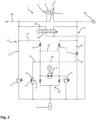
- Fig. 2 is a hydraulic circuit diagram of a hydraulic system 1 according to the invention for a mobile rescue stretcher 50.
- the rescue stretcher 50 is described below with reference to Fig. 3 described in more detail.
- the hydraulic system 1 has a hydraulic cylinder 2, a tank 3 and a pump 4.
- the tank 3 is designed as a hydraulic accumulator, although other designs are also conceivable, for example as in Fig. 1 shown.
- the hydraulic cylinder 2 has a piston 5 with a piston rod 6, which separates a first working chamber 7 and a second working chamber 8.
- the first working chamber 7 is the piston working chamber and the second working chamber 8 is the rod working chamber.
- the piston working chamber 7 is connected to the pump 4 via a first line arrangement 9 and the rod working chamber 8 is connected to the pump 4 via a second line arrangement 10.
- the pump 4 is designed such that either the piston working chamber 7 can be pressurized via the first line arrangement 9 or the rod working chamber 8 can be pressurized via the second line arrangement 10. Accordingly, the hydraulic fluid from the other, non-pressurized working chamber 7, 8 flows out via the respective line arrangement 9, 10.
- the hydraulic system 1 has a first check valve 11 arranged in the first line arrangement.
- the first check valve 11 is designed as a spring-loaded check valve and is connected to the second line arrangement 10 via a first control line 23 such that the first check valve 11 is opened when the second line arrangement 10 or the rod working chamber 8 is pressurized to retract the hydraulic cylinder 2.
- the hydraulic fluid displaced from the piston working chamber 7 can thus be sucked in directly, at least partially, via the first line arrangement 9 and the pump 4.
- the second line arrangement 10 has a first branch line 13 and a second branch line 14.
- the first branch line 13 is connected to the pump 4 and a second check valve 12 is arranged in the first branch line 13.
- the second check valve 12 is also designed as a spring-loaded check valve in this embodiment.
- the second branch line 14 branches off downstream of the second check valve 12.
- the first control line 23 branches off upstream of the second check valve 12.
- the second branch line 14 is connected to the tank and a pressure valve 15 designed as a pressure relief valve is arranged in the second branch line 14.
- the pressure relief valve 15 limits the pressure in the second line arrangement 10 to a maximum of 100 bar, in particular to a maximum of 75 bar. This pressure is sufficient to open the first check valve 11 via the first control line 23.
- the excess hydraulic fluid volume is diverted to the tank via the pressure relief valve 15 when the hydraulic cylinder 2 is retracted. This prevents the first check valve 11 from stuttering due to a collapsing control pressure in the first control line 23.
- the second line arrangement 10 has a third branch line 16 which branches off from the first branch line 13 between the pump 3 and the second check valve 12 and is connected to the tank 3.
- a nozzle 17 is arranged in the third branch line 16. This nozzle 17 is selected to be very small.
- the third branch line 16 has a bypass line 18 which bypasses the nozzle 17 and has a third check valve 19 which is also designed as a spring-loaded check valve.
- the first line arrangement 9 has a fourth branch line 20 which is connected to the tank 3.
- the fourth branch line 18 branches off in the flow direction from the pump 3 to the piston working chamber 7 downstream of the first check valve 11.
- the fourth branch line 20 is a fourth, also spring-loaded check valve 21, which is connected to the second line arrangement 10 via a second control line 24 in such a way that it is opened when the second line arrangement 10 is pressurized.
- the second control line 24 branches off from the second line arrangement 10 or the first branch line 13 between the pump 3 and the second check valve 12.
- a hydraulic resistance 22 designed as a nozzle is arranged in front of the fourth check valve 21. This allows a defined partial volume of the hydraulic fluid volume displaced from the piston working chamber 7 to be removed from the circuit when the hydraulic cylinder 2 is retracted. This enables the hydraulic cylinder 2 to be retracted more quickly overall.
- the hydraulic system 1 has a manually operable emergency valve 25 which connects the piston working chamber 7 and the rod working chamber 8 directly to the tank 3.
- a nozzle 26 is arranged between the rod working chamber 8 and the emergency valve 25.
- the hydraulic system 1 also has an emergency pressure relief valve 27, which connects the first line arrangement 9 to the tank 3.
- the emergency pressure relief valve 27 is set to a pressure of more than 200 bar and prevents damage to the hydraulic system 1 that could otherwise occur if the hydraulic cylinder 2 is blocked from the outside or if the hydraulic cylinder 2 moves to the end stop. Furthermore, this could also occur if pressure increases could occur due to temperature or sunlight, for example.
- the hydraulic system 1 also has an optional external connection 28 and an optional pressure gauge 29.
- the hydraulic system 1 further comprises a suction arrangement 30, via which the pump 4 can directly suck in hydraulic fluid from the tank 3.
- a suction arrangement 30 via which the pump 4 can directly suck in hydraulic fluid from the tank 3.
- a variant with two spring-loaded check valves is shown, although other variants are also conceivable, for example with a shuttle valve.
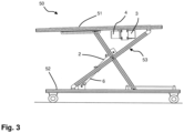
- a side view of a mobile rescue stretcher 50 according to the invention is shown.
- the rescue stretcher 50 has a patient stretcher 51, a chassis 52, a scissor lift construction 53 and a hydraulic system 1 described above.
- the hydraulic cylinder 2 is attached to the scissor lift construction 53 and the chassis 52 in such a way that pressurization of the first line arrangement 9 and thus the piston working chamber 7 raises the patient stretcher 51 relative to the chassis 52. Accordingly, the patient stretcher 51 is lowered relative to the chassis 52 when pressurization of the second line arrangement 10 and thus the rod working chamber 8 is applied.
- the pump 4 is controlled so that the first line arrangement 9 is subjected to pressure.
- the hydraulic fluid displaced from the rod working chamber 8 can flow to the tank 3 via the second line arrangement 10 and the second branch line 14, since the pressure exceeds the pressure set on the pressure relief valve 15 and the pressure relief valve 15 therefore opens.
- the pump 3 sucks hydraulic fluid from the tank 3 via the fourth branch line 16 and the bypass line 18 as well as via the suction arrangement 30.
- the pump 3 is turned off and the position of the hydraulic cylinder 2 is held via the first check valve 11 and the fourth check valve 21.
- the pump 4 is controlled so that the second line arrangement 10 is pressurized.
- the first check valve 11 and the fourth check valve 21 are opened via the control pressure reported by the first and second control lines 23, 24.
- the hydraulic fluid displaced from the piston working chamber 7 can thus be sucked in again directly via the pump 4 or partially flow off to the tank 3 via the fourth branch line 20.
- the pressure in the second line arrangement 10 or in the first branch line 13 opens the second check valve 12 and hydraulic fluid can flow into the rod working chamber 8.
- the excess volume of the hydraulic fluid flowing out of the piston working chamber 7 is diverted to the tank 3 via the pressure relief valve 15 and the pressure in the second line arrangement 9 is limited to the pressure set on the pressure relief valve 15.
- the pump 4 is stopped.
- the second check valve 12 closes and control pressure in the first control line 23 and in the second control line 24 is relieved via the third branch line 16 and the nozzle 17 to the tank 3.
- the first check valve 11 and the fourth check valve 21 close and the position of the patient bed 51 is maintained.
- the above functional descriptions of the mobile rescue stretcher 50 also apply accordingly to a quick retraction ("retract”) or extension ("extend”) of the chassis 51, i.e. for a situation in which no patient is on the patient stretcher 51. This is necessary, for example, if the rescue stretcher 51 is to be hung in an ambulance or removed from the ambulance.
Landscapes
- Engineering & Computer Science (AREA)
- Physics & Mathematics (AREA)
- Fluid Mechanics (AREA)
- Mechanical Engineering (AREA)
- General Engineering & Computer Science (AREA)
- Health & Medical Sciences (AREA)
- Life Sciences & Earth Sciences (AREA)
- Animal Behavior & Ethology (AREA)
- General Health & Medical Sciences (AREA)
- Public Health (AREA)
- Veterinary Medicine (AREA)
- Invalid Beds And Related Equipment (AREA)
Claims (9)
- Système hydraulique (1) pour un brancard de sauvetage mobile (50) comprenant un vérin hydraulique (2), un réservoir (3) et une pompe (4),le vérin hydraulique (2) comprenant un piston (5) comportant au moins une tige de piston (6), un premier espace de travail (7) et un deuxième espace de travail (7) séparé du premier espace de travail (7) par le piston (5),le premier espace de travail (7) étant connecté à la pompe (4) par un premier ensemble de conduits (9) et le deuxième espace de travail (8) étant connecté à la pompe (4) par un deuxième ensemble de conduits (10),le premier espace de travail (7) par le premier ensemble de conduits (9) ou le deuxième espace de travail (8) par le deuxième ensemble de conduits (10) étant destiné à être pressurisé sélectivement par la pompe (4),lors d'une pressurisation du deuxième espace de travail (8), du fluide hydraulique étant déchargé du premier espace de travail (7) par le premier ensemble de conduits (9) ce qui est effectué par le fait que le premier ensemble de conduits (9) est doté d'un premier clapet anti-retour (11) dont l'ouverture est commandée lors d'une pressurisation du deuxième ensemble de conduits (10), etlors d'une pressurisation du premier espace de travail (7), du fluide hydraulique étant déchargé du deuxième espace de travail (8) par le deuxième ensemble de conduits (10), caractérisé en ce quele deuxième ensemble de conduits (10) comprend un premier conduit de dérivation (13) connecté à la pompe (4) et un deuxième conduit de dérivation (14) connecté au réservoir (3), une soupape de pression (15) étant disposée dans le deuxième conduit de dérivation (14) et étant destinée à ouvrir lors d'une pressurisation du deuxième ensemble de conduits (10) de sorte que la pression dans le deuxième ensemble de conduits (10) est limitée à une pression qui est préréglée sur la soupape et qui est suffisante pour commander l'ouverture du premier clapet anti-retour (11) et un débit volumique excédentaire est amené au réservoir (3) via ladite soupape de pression (15), la pression préréglée sur ladite soupape de pression (15) étant inférieure à la pression de refoulement de la pompe, etun deuxième clapet anti-retour (12) étant disposée dans le premier conduit de dérivation (13) de sorte que lors de la sortie du vérin hydraulique (2) le deuxième espace de travail (10) est décomprimé vers le réservoir (3) via la soupape de pression (15).
- Système hydraulique (1) selon la revendication 1,
caractérisé en ce que
la soupape de pression (15) est une soupape de limitation de pression. - Système hydraulique (1) selon la revendication 1 ou 2,
caractérisé en ce que
la soupape de pression (15) est destinée à ouvrir sous une pression de 100 bar au maximum, en particulier sous une pression de 75 bar au maximum. - Système hydraulique (1) selon l'une quelconque des revendications précédentes, caractérisé en ce que
le deuxième ensemble de conduits (10) comprend un troisième conduit de dérivation (16) connecté au réservoir (3), le troisième conduit de dérivation (16) bifurquant du premier conduit de dérivation (13) et une buse (17) étant disposée dans le troisième conduit de dérivation (16). - Système hydraulique (1) selon la revendication 4,
caractérisé en ce que
le troisième conduit de dérivation (16) comprend un conduit de contournement (18) qui contourne la buse (17) et qui comprend un troisième clapet anti-retour (19). - Système hydraulique (1) selon l'une quelconque des revendications précédentes, caractérisé en ce que
le premier ensemble de conduits (9) comprend un quatrième conduit de dérivation (20) connecté au réservoir (3), un quatrième clapet anti-retour (21) dont l'ouverture est commandée lors d'une pressurisation du deuxième ensemble de conduits (10) étant disposée dans le quatrième conduit de dérivation (20). - Système hydraulique (1) selon la revendication 6,
caractérisé en ce que
une résistance hydraulique (22) est disposée dans le quatrième conduit de dérivation (20), ladite résistance hydraulique (22) étant en particulier une buse. - Système hydraulique (1) selon la revendication 7,
caractérisé en ce que
ladite résistance hydraulique (22) est, en direction d'écoulement depuis le premier espace de travail (7) vers le réservoir (3), disposée en amont du quatrième clapet anti-retour (21) dans le quatrième conduit de dérivation (20). - Brancard de sauvetage mobile (50) comprenant un système hydraulique (1) selon l'une quelconque des revendications précédentes.
Applications Claiming Priority (1)
| Application Number | Priority Date | Filing Date | Title |
|---|---|---|---|
| DE102021204291.0A DE102021204291B3 (de) | 2021-04-29 | 2021-04-29 | Hydrauliksystem für eine fahrbare Rettungsliege und fahrbare Rettungsliege |
Publications (2)
| Publication Number | Publication Date |
|---|---|
| EP4082501A1 EP4082501A1 (fr) | 2022-11-02 |
| EP4082501B1 true EP4082501B1 (fr) | 2024-10-30 |
Family
ID=80780460
Family Applications (1)
| Application Number | Title | Priority Date | Filing Date |
|---|---|---|---|
| EP22162064.4A Active EP4082501B1 (fr) | 2021-04-29 | 2022-03-15 | Système hydraulique pour un brancard de sauvetage mobile et brancard de sauvetage mobile |
Country Status (4)
| Country | Link |
|---|---|
| US (1) | US11679043B2 (fr) |
| EP (1) | EP4082501B1 (fr) |
| CN (1) | CN115263829B (fr) |
| DE (1) | DE102021204291B3 (fr) |
Family Cites Families (11)
| Publication number | Priority date | Publication date | Assignee | Title |
|---|---|---|---|---|
| AT409656B (de) * | 1999-10-18 | 2002-10-25 | Hoerbiger Hydraulik | Hydraulische betätigungsanordnung |
| US7996939B2 (en) * | 2004-06-14 | 2011-08-16 | Ferno-Washington, Inc. | Electro-hydraulically powered lift ambulance cot |
| US7398571B2 (en) | 2004-09-24 | 2008-07-15 | Stryker Corporation | Ambulance cot and hydraulic elevating mechanism therefor |
| DE102004048642A1 (de) * | 2004-10-04 | 2006-04-06 | Bosch Rexroth Aktiengesellschaft | Hydraulische Steueranordnung |
| US7254945B1 (en) * | 2006-02-27 | 2007-08-14 | Kayaba Industry Co., Ltd. | Operate check valve and hydraulic driving unit |
| JP6093535B2 (ja) | 2012-10-10 | 2017-03-08 | Kyb株式会社 | シリンダ駆動装置 |
| CN203879827U (zh) * | 2014-05-28 | 2014-10-15 | 吴汀 | 一种伺服驱动液压系统 |
| US10987260B2 (en) * | 2017-04-21 | 2021-04-27 | Stryker Corporation | Patient handling apparatus with hydraulic control system |
| JP6467479B1 (ja) * | 2017-09-29 | 2019-02-13 | 川崎重工業株式会社 | 液圧システム |
| DE102018109352A1 (de) * | 2018-04-19 | 2019-10-24 | HAWE Altenstadt Holding GmbH | Fahrbare Rettungsliege |
| US11896531B2 (en) * | 2019-10-28 | 2024-02-13 | Stryker Corporation | Hydraulic circuit for a patient handling apparatus |
-
2021
- 2021-04-29 DE DE102021204291.0A patent/DE102021204291B3/de not_active Withdrawn - After Issue
-
2022
- 2022-02-11 US US17/669,769 patent/US11679043B2/en active Active
- 2022-03-15 EP EP22162064.4A patent/EP4082501B1/fr active Active
- 2022-03-31 CN CN202210332805.0A patent/CN115263829B/zh active Active
Also Published As
| Publication number | Publication date |
|---|---|
| CN115263829B (zh) | 2026-03-10 |
| US20220347023A1 (en) | 2022-11-03 |
| DE102021204291B3 (de) | 2022-06-15 |
| US11679043B2 (en) | 2023-06-20 |
| EP4082501A1 (fr) | 2022-11-02 |
| CN115263829A (zh) | 2022-11-01 |
Similar Documents
| Publication | Publication Date | Title |
|---|---|---|
| EP1915538B1 (fr) | Montage pour commander un cylindre d'entrainement hydraulique a double effet | |
| EP3254549B1 (fr) | Engin agricole | |
| EP2174538A1 (fr) | Appareil de travail, notamment pour l'agencement sur la face arrière ou avant d'un véhicule agricole | |
| EP3761936B1 (fr) | Brancard de sauvetage mobile | |
| EP3597584B1 (fr) | Dispositif de verrouillage de flèche télescopique | |
| DE102021214583B3 (de) | Hydrauliksystem für einen Bremslüfter, Bremslüfter mit einem solchen Hydrauliksystem und Bremssystem | |
| EP4321471A1 (fr) | Système hydraulique pour un chariot de manutention | |
| DE102017107994B4 (de) | Kraftfahrzeug-Fahrgestell | |
| DE102021204291B3 (de) | Hydrauliksystem für eine fahrbare Rettungsliege und fahrbare Rettungsliege | |
| EP2251550A2 (fr) | Système hydraulique et engin de construction mobile | |
| DE202012009568U1 (de) | Hydraulischer Hubzylinder und Hebesystem mit einem solchen Hubzylinder | |
| EP4385938B1 (fr) | Dispositif de soupape pour un chariot de manutention | |
| EP2349762B1 (fr) | Dispositif d'actionnement hydraulique pour une capote de véhicule | |
| EP4275465A1 (fr) | Dispositif de réglage hydraulique | |
| DE102021204032B4 (de) | Hydraulische Steuereinheit für einen Bootsantrieb und Bootsantrieb mit einer solchen Steuereinheit | |
| DE4418881A1 (de) | Hubwerkregelsystem mit Regelventil | |
| EP4079141B1 (fr) | Andaineuse | |
| EP2639104B1 (fr) | Commande hydraulique d'un vérin de basculement facilement actionnable | |
| EP3597588B1 (fr) | Chariot de manutention doté d'un système hydraulique ainsi que procédé de fonctionnement d'un système hydraulique | |
| DE3801007C2 (de) | Eilgangschaltung für einen Schubzylinder, insbesondere für einen Schubzylinder eines Ladekranes | |
| DE102021209014A1 (de) | Hydraulische Antriebseinheit für eine Krankentrageliege und Krankentrageliege mit einer solchen hydraulischen Antriebseinheit | |
| DE102020207787A1 (de) | Hydraulische Hubvorrichtung für ein Fahrgestell einer mobilen Vorrichtung, Fahrgestell sowie mobile Vorrichtung | |
| DE102020209387B3 (de) | Vorwahlventil, Hydraulikventilverband und Hydrauliksteuervorrichtung | |
| DE2645752B1 (de) | Hydraulisch laengenveraenderbarer Oberlenker | |
| EP4725893A1 (fr) | Procédé de fonctionnement d'un système hydraulique comprenant plusieurs pompes hydrauliques d'un chariot de manutention et chariot de manutention |
Legal Events
| Date | Code | Title | Description |
|---|---|---|---|
| PUAI | Public reference made under article 153(3) epc to a published international application that has entered the european phase |
Free format text: ORIGINAL CODE: 0009012 |
|
| STAA | Information on the status of an ep patent application or granted ep patent |
Free format text: STATUS: THE APPLICATION HAS BEEN PUBLISHED |
|
| AK | Designated contracting states |
Kind code of ref document: A1 Designated state(s): AL AT BE BG CH CY CZ DE DK EE ES FI FR GB GR HR HU IE IS IT LI LT LU LV MC MK MT NL NO PL PT RO RS SE SI SK SM TR |
|
| STAA | Information on the status of an ep patent application or granted ep patent |
Free format text: STATUS: REQUEST FOR EXAMINATION WAS MADE |
|
| 17P | Request for examination filed |
Effective date: 20221202 |
|
| RBV | Designated contracting states (corrected) |
Designated state(s): AL AT BE BG CH CY CZ DE DK EE ES FI FR GB GR HR HU IE IS IT LI LT LU LV MC MK MT NL NO PL PT RO RS SE SI SK SM TR |
|
| P01 | Opt-out of the competence of the unified patent court (upc) registered |
Effective date: 20230523 |
|
| GRAP | Despatch of communication of intention to grant a patent |
Free format text: ORIGINAL CODE: EPIDOSNIGR1 |
|
| STAA | Information on the status of an ep patent application or granted ep patent |
Free format text: STATUS: GRANT OF PATENT IS INTENDED |
|
| INTG | Intention to grant announced |
Effective date: 20240529 |
|
| GRAS | Grant fee paid |
Free format text: ORIGINAL CODE: EPIDOSNIGR3 |
|
| GRAA | (expected) grant |
Free format text: ORIGINAL CODE: 0009210 |
|
| STAA | Information on the status of an ep patent application or granted ep patent |
Free format text: STATUS: THE PATENT HAS BEEN GRANTED |
|
| AK | Designated contracting states |
Kind code of ref document: B1 Designated state(s): AL AT BE BG CH CY CZ DE DK EE ES FI FR GB GR HR HU IE IS IT LI LT LU LV MC MK MT NL NO PL PT RO RS SE SI SK SM TR |
|
| REG | Reference to a national code |
Ref country code: GB Ref legal event code: FG4D Free format text: NOT ENGLISH |
|
| REG | Reference to a national code |
Ref country code: CH Ref legal event code: EP |
|
| REG | Reference to a national code |
Ref country code: IE Ref legal event code: FG4D Free format text: LANGUAGE OF EP DOCUMENT: GERMAN |
|
| REG | Reference to a national code |
Ref country code: DE Ref legal event code: R096 Ref document number: 502022001992 Country of ref document: DE |
|
| REG | Reference to a national code |
Ref country code: LT Ref legal event code: MG9D |
|
| REG | Reference to a national code |
Ref country code: NL Ref legal event code: MP Effective date: 20241030 |
|
| PG25 | Lapsed in a contracting state [announced via postgrant information from national office to epo] |
Ref country code: HR Free format text: LAPSE BECAUSE OF FAILURE TO SUBMIT A TRANSLATION OF THE DESCRIPTION OR TO PAY THE FEE WITHIN THE PRESCRIBED TIME-LIMIT Effective date: 20241030 Ref country code: PT Free format text: LAPSE BECAUSE OF FAILURE TO SUBMIT A TRANSLATION OF THE DESCRIPTION OR TO PAY THE FEE WITHIN THE PRESCRIBED TIME-LIMIT Effective date: 20250228 Ref country code: IS Free format text: LAPSE BECAUSE OF FAILURE TO SUBMIT A TRANSLATION OF THE DESCRIPTION OR TO PAY THE FEE WITHIN THE PRESCRIBED TIME-LIMIT Effective date: 20250228 |
|
| PG25 | Lapsed in a contracting state [announced via postgrant information from national office to epo] |
Ref country code: NL Free format text: LAPSE BECAUSE OF FAILURE TO SUBMIT A TRANSLATION OF THE DESCRIPTION OR TO PAY THE FEE WITHIN THE PRESCRIBED TIME-LIMIT Effective date: 20241030 Ref country code: FI Free format text: LAPSE BECAUSE OF FAILURE TO SUBMIT A TRANSLATION OF THE DESCRIPTION OR TO PAY THE FEE WITHIN THE PRESCRIBED TIME-LIMIT Effective date: 20241030 |
|
| PG25 | Lapsed in a contracting state [announced via postgrant information from national office to epo] |
Ref country code: BG Free format text: LAPSE BECAUSE OF FAILURE TO SUBMIT A TRANSLATION OF THE DESCRIPTION OR TO PAY THE FEE WITHIN THE PRESCRIBED TIME-LIMIT Effective date: 20241030 |
|
| PG25 | Lapsed in a contracting state [announced via postgrant information from national office to epo] |
Ref country code: ES Free format text: LAPSE BECAUSE OF FAILURE TO SUBMIT A TRANSLATION OF THE DESCRIPTION OR TO PAY THE FEE WITHIN THE PRESCRIBED TIME-LIMIT Effective date: 20241030 |
|
| PG25 | Lapsed in a contracting state [announced via postgrant information from national office to epo] |
Ref country code: NO Free format text: LAPSE BECAUSE OF FAILURE TO SUBMIT A TRANSLATION OF THE DESCRIPTION OR TO PAY THE FEE WITHIN THE PRESCRIBED TIME-LIMIT Effective date: 20250130 |
|
| PG25 | Lapsed in a contracting state [announced via postgrant information from national office to epo] |
Ref country code: LV Free format text: LAPSE BECAUSE OF FAILURE TO SUBMIT A TRANSLATION OF THE DESCRIPTION OR TO PAY THE FEE WITHIN THE PRESCRIBED TIME-LIMIT Effective date: 20241030 Ref country code: GR Free format text: LAPSE BECAUSE OF FAILURE TO SUBMIT A TRANSLATION OF THE DESCRIPTION OR TO PAY THE FEE WITHIN THE PRESCRIBED TIME-LIMIT Effective date: 20250131 |
|
| PG25 | Lapsed in a contracting state [announced via postgrant information from national office to epo] |
Ref country code: PL Free format text: LAPSE BECAUSE OF FAILURE TO SUBMIT A TRANSLATION OF THE DESCRIPTION OR TO PAY THE FEE WITHIN THE PRESCRIBED TIME-LIMIT Effective date: 20241030 |
|
| PG25 | Lapsed in a contracting state [announced via postgrant information from national office to epo] |
Ref country code: RS Free format text: LAPSE BECAUSE OF FAILURE TO SUBMIT A TRANSLATION OF THE DESCRIPTION OR TO PAY THE FEE WITHIN THE PRESCRIBED TIME-LIMIT Effective date: 20250130 |
|
| PG25 | Lapsed in a contracting state [announced via postgrant information from national office to epo] |
Ref country code: SM Free format text: LAPSE BECAUSE OF FAILURE TO SUBMIT A TRANSLATION OF THE DESCRIPTION OR TO PAY THE FEE WITHIN THE PRESCRIBED TIME-LIMIT Effective date: 20241030 |
|
| PG25 | Lapsed in a contracting state [announced via postgrant information from national office to epo] |
Ref country code: DK Free format text: LAPSE BECAUSE OF FAILURE TO SUBMIT A TRANSLATION OF THE DESCRIPTION OR TO PAY THE FEE WITHIN THE PRESCRIBED TIME-LIMIT Effective date: 20241030 |
|
| PG25 | Lapsed in a contracting state [announced via postgrant information from national office to epo] |
Ref country code: EE Free format text: LAPSE BECAUSE OF FAILURE TO SUBMIT A TRANSLATION OF THE DESCRIPTION OR TO PAY THE FEE WITHIN THE PRESCRIBED TIME-LIMIT Effective date: 20241030 |
|
| PG25 | Lapsed in a contracting state [announced via postgrant information from national office to epo] |
Ref country code: RO Free format text: LAPSE BECAUSE OF FAILURE TO SUBMIT A TRANSLATION OF THE DESCRIPTION OR TO PAY THE FEE WITHIN THE PRESCRIBED TIME-LIMIT Effective date: 20241030 |
|
| PG25 | Lapsed in a contracting state [announced via postgrant information from national office to epo] |
Ref country code: SK Free format text: LAPSE BECAUSE OF FAILURE TO SUBMIT A TRANSLATION OF THE DESCRIPTION OR TO PAY THE FEE WITHIN THE PRESCRIBED TIME-LIMIT Effective date: 20241030 |
|
| PG25 | Lapsed in a contracting state [announced via postgrant information from national office to epo] |
Ref country code: CZ Free format text: LAPSE BECAUSE OF FAILURE TO SUBMIT A TRANSLATION OF THE DESCRIPTION OR TO PAY THE FEE WITHIN THE PRESCRIBED TIME-LIMIT Effective date: 20241030 |
|
| PG25 | Lapsed in a contracting state [announced via postgrant information from national office to epo] |
Ref country code: IT Free format text: LAPSE BECAUSE OF FAILURE TO SUBMIT A TRANSLATION OF THE DESCRIPTION OR TO PAY THE FEE WITHIN THE PRESCRIBED TIME-LIMIT Effective date: 20241030 |
|
| REG | Reference to a national code |
Ref country code: DE Ref legal event code: R097 Ref document number: 502022001992 Country of ref document: DE |
|
| PLBE | No opposition filed within time limit |
Free format text: ORIGINAL CODE: 0009261 |
|
| STAA | Information on the status of an ep patent application or granted ep patent |
Free format text: STATUS: NO OPPOSITION FILED WITHIN TIME LIMIT |
|
| PG25 | Lapsed in a contracting state [announced via postgrant information from national office to epo] |
Ref country code: SE Free format text: LAPSE BECAUSE OF FAILURE TO SUBMIT A TRANSLATION OF THE DESCRIPTION OR TO PAY THE FEE WITHIN THE PRESCRIBED TIME-LIMIT Effective date: 20241030 |
|
| 26N | No opposition filed |
Effective date: 20250731 |
|
| PG25 | Lapsed in a contracting state [announced via postgrant information from national office to epo] |
Ref country code: MC Free format text: LAPSE BECAUSE OF FAILURE TO SUBMIT A TRANSLATION OF THE DESCRIPTION OR TO PAY THE FEE WITHIN THE PRESCRIBED TIME-LIMIT Effective date: 20241030 |
|
| REG | Reference to a national code |
Ref country code: CH Ref legal event code: H13 Free format text: ST27 STATUS EVENT CODE: U-0-0-H10-H13 (AS PROVIDED BY THE NATIONAL OFFICE) Effective date: 20251023 |
|
| PG25 | Lapsed in a contracting state [announced via postgrant information from national office to epo] |
Ref country code: LU Free format text: LAPSE BECAUSE OF NON-PAYMENT OF DUE FEES Effective date: 20250315 |
|
| REG | Reference to a national code |
Ref country code: BE Ref legal event code: MM Effective date: 20250331 |
|
| PG25 | Lapsed in a contracting state [announced via postgrant information from national office to epo] |
Ref country code: FR Free format text: LAPSE BECAUSE OF NON-PAYMENT OF DUE FEES Effective date: 20250331 |
|
| PG25 | Lapsed in a contracting state [announced via postgrant information from national office to epo] |
Ref country code: BE Free format text: LAPSE BECAUSE OF NON-PAYMENT OF DUE FEES Effective date: 20250331 |
|
| PG25 | Lapsed in a contracting state [announced via postgrant information from national office to epo] |
Ref country code: CH Free format text: LAPSE BECAUSE OF NON-PAYMENT OF DUE FEES Effective date: 20250331 |
|
| PG25 | Lapsed in a contracting state [announced via postgrant information from national office to epo] |
Ref country code: IE Free format text: LAPSE BECAUSE OF NON-PAYMENT OF DUE FEES Effective date: 20250315 |
|
| PGFP | Annual fee paid to national office [announced via postgrant information from national office to epo] |
Ref country code: DE Payment date: 20260318 Year of fee payment: 5 |
|
| PGFP | Annual fee paid to national office [announced via postgrant information from national office to epo] |
Ref country code: AT Payment date: 20260301 Year of fee payment: 5 |