EP4082655B1 - Régénérateur à lit fluidisé, appareil pour préparer une oléfine à faible teneur en carbone et application de celui-ci - Google Patents
Régénérateur à lit fluidisé, appareil pour préparer une oléfine à faible teneur en carbone et application de celui-ci Download PDFInfo
- Publication number
- EP4082655B1 EP4082655B1 EP20957238.7A EP20957238A EP4082655B1 EP 4082655 B1 EP4082655 B1 EP 4082655B1 EP 20957238 A EP20957238 A EP 20957238A EP 4082655 B1 EP4082655 B1 EP 4082655B1
- Authority
- EP
- European Patent Office
- Prior art keywords
- zone
- gas
- fluidized bed
- catalyst
- activation zone
- Prior art date
- Legal status (The legal status is an assumption and is not a legal conclusion. Google has not performed a legal analysis and makes no representation as to the accuracy of the status listed.)
- Active
Links
Images

Classifications
-
- B—PERFORMING OPERATIONS; TRANSPORTING
- B01—PHYSICAL OR CHEMICAL PROCESSES OR APPARATUS IN GENERAL
- B01J—CHEMICAL OR PHYSICAL PROCESSES, e.g. CATALYSIS OR COLLOID CHEMISTRY; THEIR RELEVANT APPARATUS
- B01J29/00—Catalysts comprising molecular sieves
- B01J29/82—Phosphates
- B01J29/84—Aluminophosphates containing other elements, e.g. metals, boron
- B01J29/85—Silicoaluminophosphates [SAPO compounds]
-
- B—PERFORMING OPERATIONS; TRANSPORTING
- B01—PHYSICAL OR CHEMICAL PROCESSES OR APPARATUS IN GENERAL
- B01J—CHEMICAL OR PHYSICAL PROCESSES, e.g. CATALYSIS OR COLLOID CHEMISTRY; THEIR RELEVANT APPARATUS
- B01J29/00—Catalysts comprising molecular sieves
- B01J29/90—Regeneration or reactivation
-
- B—PERFORMING OPERATIONS; TRANSPORTING
- B01—PHYSICAL OR CHEMICAL PROCESSES OR APPARATUS IN GENERAL
- B01J—CHEMICAL OR PHYSICAL PROCESSES, e.g. CATALYSIS OR COLLOID CHEMISTRY; THEIR RELEVANT APPARATUS
- B01J38/00—Regeneration or reactivation of catalysts, in general
- B01J38/04—Gas or vapour treating; Treating by using liquids vaporisable upon contacting spent catalyst
- B01J38/06—Gas or vapour treating; Treating by using liquids vaporisable upon contacting spent catalyst using steam
-
- B—PERFORMING OPERATIONS; TRANSPORTING
- B01—PHYSICAL OR CHEMICAL PROCESSES OR APPARATUS IN GENERAL
- B01J—CHEMICAL OR PHYSICAL PROCESSES, e.g. CATALYSIS OR COLLOID CHEMISTRY; THEIR RELEVANT APPARATUS
- B01J38/00—Regeneration or reactivation of catalysts, in general
- B01J38/04—Gas or vapour treating; Treating by using liquids vaporisable upon contacting spent catalyst
- B01J38/12—Treating with free oxygen-containing gas
- B01J38/14—Treating with free oxygen-containing gas with control of oxygen content in oxidation gas
-
- B—PERFORMING OPERATIONS; TRANSPORTING
- B01—PHYSICAL OR CHEMICAL PROCESSES OR APPARATUS IN GENERAL
- B01J—CHEMICAL OR PHYSICAL PROCESSES, e.g. CATALYSIS OR COLLOID CHEMISTRY; THEIR RELEVANT APPARATUS
- B01J38/00—Regeneration or reactivation of catalysts, in general
- B01J38/04—Gas or vapour treating; Treating by using liquids vaporisable upon contacting spent catalyst
- B01J38/12—Treating with free oxygen-containing gas
- B01J38/16—Oxidation gas comprising essentially steam and oxygen
-
- B—PERFORMING OPERATIONS; TRANSPORTING
- B01—PHYSICAL OR CHEMICAL PROCESSES OR APPARATUS IN GENERAL
- B01J—CHEMICAL OR PHYSICAL PROCESSES, e.g. CATALYSIS OR COLLOID CHEMISTRY; THEIR RELEVANT APPARATUS
- B01J38/00—Regeneration or reactivation of catalysts, in general
- B01J38/04—Gas or vapour treating; Treating by using liquids vaporisable upon contacting spent catalyst
- B01J38/12—Treating with free oxygen-containing gas
- B01J38/30—Treating with free oxygen-containing gas in gaseous suspension, e.g. fluidised bed
- B01J38/34—Treating with free oxygen-containing gas in gaseous suspension, e.g. fluidised bed with plural distinct serial combustion stages
-
- B—PERFORMING OPERATIONS; TRANSPORTING
- B01—PHYSICAL OR CHEMICAL PROCESSES OR APPARATUS IN GENERAL
- B01J—CHEMICAL OR PHYSICAL PROCESSES, e.g. CATALYSIS OR COLLOID CHEMISTRY; THEIR RELEVANT APPARATUS
- B01J8/00—Chemical or physical processes in general, conducted in the presence of fluids and solid particles; Apparatus for such processes
- B01J8/18—Chemical or physical processes in general, conducted in the presence of fluids and solid particles; Apparatus for such processes with fluidised particles
- B01J8/1818—Feeding of the fluidising gas
- B01J8/1827—Feeding of the fluidising gas the fluidising gas being a reactant
-
- B—PERFORMING OPERATIONS; TRANSPORTING
- B01—PHYSICAL OR CHEMICAL PROCESSES OR APPARATUS IN GENERAL
- B01J—CHEMICAL OR PHYSICAL PROCESSES, e.g. CATALYSIS OR COLLOID CHEMISTRY; THEIR RELEVANT APPARATUS
- B01J8/00—Chemical or physical processes in general, conducted in the presence of fluids and solid particles; Apparatus for such processes
- B01J8/18—Chemical or physical processes in general, conducted in the presence of fluids and solid particles; Apparatus for such processes with fluidised particles
- B01J8/1872—Details of the fluidised bed reactor
-
- B—PERFORMING OPERATIONS; TRANSPORTING
- B01—PHYSICAL OR CHEMICAL PROCESSES OR APPARATUS IN GENERAL
- B01J—CHEMICAL OR PHYSICAL PROCESSES, e.g. CATALYSIS OR COLLOID CHEMISTRY; THEIR RELEVANT APPARATUS
- B01J8/00—Chemical or physical processes in general, conducted in the presence of fluids and solid particles; Apparatus for such processes
- B01J8/18—Chemical or physical processes in general, conducted in the presence of fluids and solid particles; Apparatus for such processes with fluidised particles
- B01J8/24—Chemical or physical processes in general, conducted in the presence of fluids and solid particles; Apparatus for such processes with fluidised particles according to "fluidised-bed" technique
- B01J8/26—Chemical or physical processes in general, conducted in the presence of fluids and solid particles; Apparatus for such processes with fluidised particles according to "fluidised-bed" technique with two or more fluidised beds, e.g. reactor and regeneration installations
-
- C—CHEMISTRY; METALLURGY
- C07—ORGANIC CHEMISTRY
- C07C—ACYCLIC OR CARBOCYCLIC COMPOUNDS
- C07C1/00—Preparation of hydrocarbons from one or more compounds, none of them being a hydrocarbon
- C07C1/20—Preparation of hydrocarbons from one or more compounds, none of them being a hydrocarbon starting from organic compounds containing only oxygen atoms as heteroatoms
-
- C—CHEMISTRY; METALLURGY
- C07—ORGANIC CHEMISTRY
- C07C—ACYCLIC OR CARBOCYCLIC COMPOUNDS
- C07C1/00—Preparation of hydrocarbons from one or more compounds, none of them being a hydrocarbon
- C07C1/20—Preparation of hydrocarbons from one or more compounds, none of them being a hydrocarbon starting from organic compounds containing only oxygen atoms as heteroatoms
- C07C1/22—Preparation of hydrocarbons from one or more compounds, none of them being a hydrocarbon starting from organic compounds containing only oxygen atoms as heteroatoms by reduction
-
- C—CHEMISTRY; METALLURGY
- C07—ORGANIC CHEMISTRY
- C07C—ACYCLIC OR CARBOCYCLIC COMPOUNDS
- C07C11/00—Aliphatic unsaturated hydrocarbons
- C07C11/02—Alkenes
- C07C11/04—Ethene
-
- C—CHEMISTRY; METALLURGY
- C07—ORGANIC CHEMISTRY
- C07C—ACYCLIC OR CARBOCYCLIC COMPOUNDS
- C07C11/00—Aliphatic unsaturated hydrocarbons
- C07C11/02—Alkenes
- C07C11/06—Propene
-
- B—PERFORMING OPERATIONS; TRANSPORTING
- B01—PHYSICAL OR CHEMICAL PROCESSES OR APPARATUS IN GENERAL
- B01J—CHEMICAL OR PHYSICAL PROCESSES, e.g. CATALYSIS OR COLLOID CHEMISTRY; THEIR RELEVANT APPARATUS
- B01J2208/00—Processes carried out in the presence of solid particles; Reactors therefor
- B01J2208/00796—Details of the reactor or of the particulate material
- B01J2208/00823—Mixing elements
- B01J2208/00831—Stationary elements
- B01J2208/0084—Stationary elements inside the bed, e.g. baffles
-
- B—PERFORMING OPERATIONS; TRANSPORTING
- B01—PHYSICAL OR CHEMICAL PROCESSES OR APPARATUS IN GENERAL
- B01J—CHEMICAL OR PHYSICAL PROCESSES, e.g. CATALYSIS OR COLLOID CHEMISTRY; THEIR RELEVANT APPARATUS
- B01J2208/00—Processes carried out in the presence of solid particles; Reactors therefor
- B01J2208/00796—Details of the reactor or of the particulate material
- B01J2208/00991—Disengagement zone in fluidised-bed reactors
-
- C—CHEMISTRY; METALLURGY
- C07—ORGANIC CHEMISTRY
- C07C—ACYCLIC OR CARBOCYCLIC COMPOUNDS
- C07C2529/00—Catalysts comprising molecular sieves
- C07C2529/82—Phosphates
- C07C2529/84—Aluminophosphates containing other elements, e.g. metals, boron
- C07C2529/85—Silicoaluminophosphates (SAPO compounds)
-
- Y—GENERAL TAGGING OF NEW TECHNOLOGICAL DEVELOPMENTS; GENERAL TAGGING OF CROSS-SECTIONAL TECHNOLOGIES SPANNING OVER SEVERAL SECTIONS OF THE IPC; TECHNICAL SUBJECTS COVERED BY FORMER USPC CROSS-REFERENCE ART COLLECTIONS [XRACs] AND DIGESTS
- Y02—TECHNOLOGIES OR APPLICATIONS FOR MITIGATION OR ADAPTATION AGAINST CLIMATE CHANGE
- Y02P—CLIMATE CHANGE MITIGATION TECHNOLOGIES IN THE PRODUCTION OR PROCESSING OF GOODS
- Y02P20/00—Technologies relating to chemical industry
- Y02P20/50—Improvements relating to the production of bulk chemicals
- Y02P20/584—Recycling of catalysts
-
- Y—GENERAL TAGGING OF NEW TECHNOLOGICAL DEVELOPMENTS; GENERAL TAGGING OF CROSS-SECTIONAL TECHNOLOGIES SPANNING OVER SEVERAL SECTIONS OF THE IPC; TECHNICAL SUBJECTS COVERED BY FORMER USPC CROSS-REFERENCE ART COLLECTIONS [XRACs] AND DIGESTS
- Y02—TECHNOLOGIES OR APPLICATIONS FOR MITIGATION OR ADAPTATION AGAINST CLIMATE CHANGE
- Y02P—CLIMATE CHANGE MITIGATION TECHNOLOGIES IN THE PRODUCTION OR PROCESSING OF GOODS
- Y02P30/00—Technologies relating to oil refining and petrochemical industry
- Y02P30/20—Technologies relating to oil refining and petrochemical industry using bio-feedstock
-
- Y—GENERAL TAGGING OF NEW TECHNOLOGICAL DEVELOPMENTS; GENERAL TAGGING OF CROSS-SECTIONAL TECHNOLOGIES SPANNING OVER SEVERAL SECTIONS OF THE IPC; TECHNICAL SUBJECTS COVERED BY FORMER USPC CROSS-REFERENCE ART COLLECTIONS [XRACs] AND DIGESTS
- Y02—TECHNOLOGIES OR APPLICATIONS FOR MITIGATION OR ADAPTATION AGAINST CLIMATE CHANGE
- Y02P—CLIMATE CHANGE MITIGATION TECHNOLOGIES IN THE PRODUCTION OR PROCESSING OF GOODS
- Y02P30/00—Technologies relating to oil refining and petrochemical industry
- Y02P30/40—Ethylene production
Definitions
- the present application relates to a fluidized bed regenerator, a device for preparing light olefins, and use thereof, and belongs to the field of chemical catalysis.
- MTO Methanol-to-olefin technology
- DMTO methanol-to-olefin
- UOP UOP Company of the United States.
- DMTO methanol-to-olefin
- DMTO technology has been further developed, and a new generation of DMTO catalysts with better performance have gradually begun in industrial applications, creating higher benefits for DMTO plants.
- the new generation of DMTO catalyst has higher methanol processing capacity and light olefin selectivity.
- the MTO technologies generally adopt an SAPO-34 molecular sieve catalyst, and the high selectivity for light olefins in an MTO process is achieved by the combination of the acid catalysis of the molecular sieve with the restriction of pores in a framework structure of the molecular sieve.
- a methanol conversion process is also accompanied by a coking process of an acidic molecular sieve catalyst.
- the existing MTO plants can achieve a methanol coking rate of 1.5 wt% to 2.5 wt%, that is, 3.3% to 5.5% of carbon (C) atoms in methanol are converted into coke in the catalyst, and the coke is burned in a regenerator to generate CO, CO 2 , H 2 O, and the like that are discharged, with a C utilization rate only of 94.5% to 96.7%.
- C carbon
- the patent publication no. WO2015081489A1 discloses a method for raising the light olefin yield in process of preparing a light olefin using an improved oxygen-containing compound. More specifically, the present invention provides a method for using an oxygen-containing compound to prepare a light olefin, using as a reactor a multi-stage dense phase fluidized bed containing k secondary precoking zones (k ⁇ 1) and n secondary reaction zones, and using as a main equipment a multi-level dense phase fluidized bed regenerator containing m secondary regenerators (m ⁇ 2); by means of re-refining the hydrocarbons above C4 obtained from the separation stage, or the method of adding, in a reaction zone, naphtha, gasoline, condensate oil, light diesel oil, hydrogenated tail oil, or kerosene, the invention primarily solves the problems in the prior art of the uniformity of catalyst carbon deposition and carbon content being difficult to control, and light olefin yield being low.
- An MTO process is accompanied by a coking process of an acidic molecular sieve catalyst, such that coke species are formed in molecular sieve cages, triggering a catalytic process of MTO.
- the coking of the catalyst makes some active sites of the molecular sieve covered to reduce the activity of the catalyst, but the coke in the molecular sieve further limits pores in a framework structure of the molecular sieve to improve the selectivity for light olefins.
- the light olefins mentioned in the present application refer to ethylene and propylene.
- the applicants have found through research that main factors affecting the activity of a DMTO catalyst and the selectivity for light olefins include coke content, coke content distribution, and coke species in the catalyst. Under the same average coke content in catalysts, the narrower the coke content distribution, the higher the selectivity and activity of light olefins.
- Coke species in a catalyst may include polymethyl aromatic hydrocarbons, polymethyl cycloalkanes, and the like, where polymethylbenzene and polymethylnaphthalene can promote the formation of ethylene. Therefore, the control of the coke content, coke content distribution, and coke species in a catalyst is the key to control an operation window of the DMTO catalyst and improve the selectivity of light olefins.
- a coke content in an MTO spent catalyst is generally 7 wt% to 13 wt%, and a too-high coke content will greatly reduce the activity of the catalyst.
- MTO plants generally adopt an air regeneration method to restore the activity of a catalyst, thereby recycling the catalyst; and in this process, the coke is burned in a regenerator to generate CO, CO 2 , H 2 O, and other substances, which are discharged.
- the coke in spent catalysts can be divided into two categories: coke with a large molecular weight, a high graphitization degree, and no catalytic activity, which can be called inactive coke; and polymethyl aromatic hydrocarbons and polymethyl cycloalkanes with a small molecular weight and catalytic activity, which can be called active coke.
- inactive coke and active coke undergo a deep oxidation reaction with oxygen to mainly generate substances such as CO, CO 2 , and H 2 O, and it is difficult to realize the controllable conversion of coke and control the coke content, coke content distribution, and coke species in the catalyst.
- a regenerated catalyst obtained by this regeneration scheme shows low selectivity for light olefins, high methanol coking rate, and high methanol unit consumption.
- active coke reacts with water, large-molecule species are converted into small-molecule species, and under suitable conditions, active coke can be converted into species mainly composed of polymethylbenzene and polymethylnaphthalene.
- oxygen-containing hydrocarbon species When a combination of water and oxygen is used as a regeneration medium, under the action of oxygen and water, inactive coke and active coke are converted into oxygen-containing hydrocarbon species and oxygen-free hydrocarbon species with a small molecular weight, where oxygen-containing hydrocarbon species do not have catalytic activity.
- the oxygen-containing hydrocarbon species can be converted into oxygen-free hydrocarbon species with catalytic activity under the action of substances such as water vapor, hydrogen, methane, ethane, and propane.
- the present application provides a controllable activation method for converting a spent catalyst into a regenerated catalyst, where the regenerated catalyst has the characteristics of high activity, high selectivity for light olefins, and the like, and can reduce the methanol unit consumption and methanol coking rate and improve the atomic economy of the MTO technology.
- a fluidized bed regenerator for activating a catalyst to prepare light olefins from an oxygen-containing compound is provided.
- a fluidized bed regenerator for activating a catalyst to prepare light olefins from an oxygen-containing compound where the fluidized bed regenerator includes a second activation zone, a first activation zone, and a gas-solid separation zone from bottom to top;
- the n baffles may include a 1 st baffle, and a 2 nd baffle to an n th baffle;
- one or more catalyst circulation holes can be formed in each of the baffles, which is not strictly limited in the present application.
- a plurality of catalyst circulation holes are formed, relative positions of the catalyst circulation holes are not strictly limited in the present application.
- the plurality of catalyst circulation holes may be arranged in parallel, or may be arranged randomly.
- a first activation zone distributor may be provided beneath each of the first activation zone subzones.
- a first activation zone raw material can enter the first activation zone subzones uniformly as a whole.
- a top of each of the first activation zone subzones may be provided with a first activation zone gas delivery pipe.
- the first activation zone raw material may contact and react with a spent catalyst through the first activation zone distributor.
- a first gas-solid separation unit of the regenerator may be arranged in an upper part of the first activation zone; and the first gas-solid separation unit of the regenerator may communicate with the first activation zone through the spent catalyst inlet.
- the spent catalyst may enter the first activation zone through the first gas-solid separation unit.
- the first activation zone may be provided with a first activation zone catalyst delivery pipe, an inlet of the first activation zone catalyst delivery pipe may be connected to the n th first activation zone subzone, and an outlet of the first activation zone catalyst delivery pipe may be formed in the second activation zone.
- the first gas-solid separation unit of the regenerator may be a gas-solid cyclone separator.
- n may have a value range of 2 ⁇ n ⁇ 10.
- a cross section of each of the first activation zone subzones may be sector-annular.
- the perforated plates may have a porosity of 5% to 50%.
- perforated plates are arranged in the second activation zone to inhibit the back-mixing of a catalyst among beds and improve the uniformity of coke distribution in the catalyst.
- a second activation zone distributor may be arranged at a bottom of the second activation zone.
- the fluidized bed regenerator may include a regenerator gas collection chamber and a fluidized bed regenerator cooler;
- an inner diameter of a junction between the second activation zone and the gas-solid separation zone may gradually increase.
- an inner diameter of a junction between the lower shell and the upper shell of the fluidized bed regenerator may gradually increase.
- the second gas-solid separation unit of the regenerator may adopt one or more sets of gas-solid cyclone separators.
- each set of gas-solid cyclone separators may include a first-stage gas-solid cyclone separator and a second-stage gas-solid cyclone separator.
- the fluidized bed regenerator may be divided into a second activation zone, a first activation zone, and a gas-solid separation zone from bottom to top;
- a device for preparing light olefins from an oxygen-containing compound is provided.
- the device is a DMTO device including a fluidized bed reactor and a fluidized bed regenerator.
- a device for preparing light olefins from an oxygen-containing compound including a fluidized bed reactor and the fluidized bed regenerator described above.
- the device may include a spent catalyst inclined pipe, a fluidized bed reactor stripper, a spent catalyst delivery pipe, a regenerated catalyst inclined pipe, and a regenerated catalyst delivery pipe;
- the spent catalyst inclined pipe, the fluidized bed reactor stripper, and the spent catalyst delivery pipe may be connected to each other in sequence;
- the fluidized bed reactor stripper and the spent catalyst delivery pipe may be connected to each other through a spent catalyst slide valve.
- the regenerated catalyst inclined pipe and the regenerated catalyst delivery pipe may be connected to each other through a regenerated catalyst slide valve.
- the fluidized bed reactor may include a lower shell, a delivery pipe, and an upper shell;
- the fluidized bed reactor may include a fluidized bed reactor distributor, a fluidized bed reactor cooler, a spent catalyst zone gas distributor, a fluidized bed reactor gas collection chamber, and a second gas-solid separation unit of the fluidized bed reactor;
- each set of gas-solid cyclone separators may include a first-stage gas-solid cyclone separator and a second-stage gas-solid cyclone separator.
- the second gas-solid separation unit of the fluidized bed reactor may adopt one or more sets of gas-solid cyclone separators.
- the fluidized bed reactor may include a fluidized bed reactor shell, a fluidized bed reactor distributor, a delivery pipe, a first gas-solid separation unit of the fluidized bed reactor, a fluidized bed reactor gas collection chamber, a spent catalyst zone gas distributor, a fluidized bed reactor cooler, a second gas-solid separation unit of the fluidized bed reactor, a product gas delivery pipe, a spent catalyst circulation pipe, a spent catalyst circulation slide valve, a spent catalyst inclined pipe, a fluidized bed reactor stripper, a spent catalyst slide valve, and a spent catalyst delivery pipe;
- a method for activating a catalyst to prepare light olefins from an oxygen-containing compound is provided.
- the method may include:
- the first activation zone raw material may enter the first activation zone through the first activation zone distributor to react with coke in the catalyst.
- the second activation zone raw material may enter the second activation zone through the second activation zone distributor to react with coke in the catalyst.
- the first activation zone raw material enters the first activation zone subzone from the first activation zone distributor located beneath, and contacts the spent catalyst, such that inactive coke and active coke in the spent catalyst are converted into oxygen-containing hydrocarbon species and oxygen-free hydrocarbon species with a small molecular weight; and a gas phase (including the unreacted first activation zone raw material) is conveyed to the gas-solid separation zone through the first activation zone gas delivery pipe above the first activation zone.
- the catalyst enters the second activation zone through the first activation zone catalyst delivery pipe, and the second activation zone raw material enters the second activation zone through the second activation zone distributor located beneath to contact the catalyst, such that catalytically-inactive oxygen-containing hydrocarbon species in coke of the catalyst are converted into catalytically-active oxygen-free hydrocarbon species; and a gas phase (including the unreacted second activation zone raw material) enters the gas-solid separation zone.
- the coke in the spent catalyst may chemically react with the first activation zone raw material to generate a first activation zone product gas.
- the coke in the partially-activated catalyst may chemically react with the second activation zone raw material to generate a second activation zone product gas.
- the first activation zone product gas and the second activation zone product gas may be mixed in the gas-solid separation zone to produce a regenerator product gas.
- a regenerator product gas carrying a catalyst may enter the second gas-solid separation unit of the regenerator to undergo gas-solid separation to obtain a regenerator product gas and a catalyst;
- the regenerator product gas may include CO, H 2 , and CO 2 ; and a content of the CO and the H 2 may be greater than 90 wt%.
- the first activation zone raw material may include oxygen, air, and water vapor;
- the second activation zone raw material may be water vapor.
- a coke content in the spent catalyst may be 9 wt% to 13 wt%.
- a coke content in the spent catalyst may be 10 wt% to 12 wt%.
- a coke content in the regenerated catalyst may be 5 wt% to 11 wt%; and a quartile deviation of a coke content distribution in the regenerated catalyst may be less than 1.0 wt%.
- coke species may include polymethylbenzene and polymethylnaphthalene
- coke content and coke content distribution in a catalyst are controlled by controlling an average residence time and a residence time distribution of the catalyst in the first activation zone and the second activation zone to make a proportion of a mass of polymethylbenzene and polymethylnaphthalene in a total mass of coke greater than or equal to 60 wt%, which improves the activity of the catalyst and the selectivity for light olefins.
- the spent catalyst may include an SAPO-34 molecular sieve.
- an active component in the catalyst may be an SAPO-34 molecular sieve.
- process operating conditions of the first activation zone of the fluidized bed regenerator may be as follows: apparent gas linear velocity: 0.1 m/s to 0.5 m/s; temperature: 650°C to 750°C; pressure: 100 kPa to 500 kPa; and bed density: 400 kg/m 3 to 700 kg/m 3 .
- process operating conditions of the second activation zone of the fluidized bed regenerator may be as follows: apparent gas linear velocity: 0.1 m/s to 0.5 m/s; temperature: 550°C to 700°C; pressure: 100 kPa to 500 kPa; and bed density: 400 kg/m 3 to 700 kg/m 3 .
- the first activation zone of the fluidized bed regenerator in the present application includes n first activation zone subzones, and a catalyst can only flow from an upstream subzone to a downstream subzone in order through the catalyst circulation holes on the baffles in the first activation zone, which shows the following beneficial effects: 1.
- Process operating conditions can be changed to control an average residence time of a catalyst in the first activation zone, thereby controlling a coke content in the catalyst.
- the structure of n first activation zone subzones is adopted to control a residence time distribution of a catalyst (the residence time distribution is similar to n serially-connected completely-mixed tank reactors), and thus a regenerated catalyst with a narrow coke content distribution can be obtained.
- the coke content in the catalyst refers to an average coke content in catalyst granules, but coke contents in different catalyst granules may actually be different.
- the quartile deviation of the coke content distribution in the regenerated catalyst can be controlled to be less than 1.0 wt%, such that the overall coke content distribution of the catalyst is narrow, thereby improving the activity of the catalyst and the selectivity for light olefins.
- an activation process of a catalyst includes two steps: S1. water vapor and oxygen are used as an activation gas to convert the inactive coke and active coke in the spent catalyst into oxygen-containing hydrocarbons species and oxygen-free hydrocarbon species with a small molecular weight, where the oxygen-containing hydrocarbon species show no catalytic activity and S1 is completed in the first activation zone; and S2.
- water vapor is used as an activation gas to convert the catalytically-inactive oxygen-containing hydrocarbon species in the coke into catalytically-active oxygen-free hydrocarbon species and further reduce the molecular weight of coke, that is, the coke in the catalyst is converted into species mainly composed of polymethylbenzene and polymethylnaphthalene, where S2 is completed in the second activation zone.
- the activation gas used can decompose the inactive coke due to strong oxidizability, but leads to the generation of some catalytically-inactive oxygen-containing hydrocarbon species; and in S2, a non-oxidative activation gas is used to further convert the catalytically-inactive oxygen-containing hydrocarbon species into catalytically-active oxygen-free hydrocarbon species.
- coke species in the regenerated catalyst are mainly polymethylbenzene and polymethylnaphthalene, with high selectivity for ethylene.
- a regeneration process of a catalyst is the coupling of an exothermic reaction and an endothermic reaction, where the first activation zone raw material and the coke in the catalyst react in the first activation zone to generate substances such as CO and H 2 , and the release of heat raises a temperature of the bed; and the second activation zone raw material and the coke in the catalyst react in the second activation zone to generate substances such as CO and H 2 , this reaction is an endothermic reaction, and the heat required by the reaction is supplied by the exothermic reaction in the first activation zone.
- a first activation zone raw material may be fed into the first activation zone of the fluidized bed regenerator from the first activation zone distributor; a spent catalyst may be fed into the first gas-solid separation unit of the regenerator from the spent catalyst delivery pipe to undergo gas-solid separation, a resulting gas may be discharged into the gas-solid separation zone of the fluidized bed regenerator through the gas outlet of the first gas-solid separation unit of the regenerator, and a resulting spent catalyst may be discharged into the first activation zone of the fluidized bed regenerator through the catalyst outlet of the first gas-solid separation unit of the regenerator; the first activation zone raw material may contact and chemically react with the spent catalyst in the first activation zone, such that the inactive coke and active coke in the spent catalyst are converted into oxygen-containing hydrocarbon species and oxygen-free hydrocarbon species with a small molecular weight and a first activation zone product gas is generated; a catalyst in the first activation zone may pass through the 1 st to n th first activation zone subzones
- the main components in the regenerator product gas are CO, H 2 , and a small amount of CO 2 , where a total content of CO and H 2 is greater than 90 wt% and a content of CO 2 is less than 10 wt% (dry basis, excluding the unconverted H 2 O); after the regenerator product gas is subjected to simple separation, a mixed gas of CO and H 2 can be obtained, and the mixed gas of CO and H 2 can be recycled as a raw material for methanol preparation; and thus, in the technical solution of the present application, the coke generated from methanol is an intermediate product of this process, and the utilization rate of C atoms in the whole process is greater than or equal to 99%.
- a method for preparing light olefins from an oxygen-containing compound is provided.
- the method may include:
- the stream A with light olefins and a spent catalyst may enter the first gas-solid separation unit of the fluidized bed reactor through the delivery pipe to undergo gas-solid separation to obtain a light olefin-containing gas and a spent catalyst.
- the spent catalyst may be stripped and then enter the fluidized bed regenerator.
- a ratio of a mass flow rate of the regenerated catalyst to a feed amount of the oxygen-containing compound may be 0.3 to 1.0 ton of catalyst/ton of methanol.
- the catalyst-to-alcohol ratio may be 0.5 to 1.0 ton of catalyst/ton of methanol.
- process operating conditions of the reaction zone of the fluidized bed reactor may be as follows: apparent gas linear velocity: 0.5 m/s to 7.0 m/s; reaction temperature: 350°C to 550°C; reaction pressure: 100 kPa to 500 kPa; and bed density: 100 kg/m 3 to 500 kg/m 3 .
- process operating conditions of the spent catalyst zone of the fluidized bed reactor may be as follows: apparent gas linear velocity: 0.1 m/s to 1.0 m/s; reaction temperature: 350°C to 550°C; reaction pressure: 100 kPa to 500 kPa; and bed density: 200 kg/m 3 to 800 kg/m 3 .
- a part of the spent catalyst in the spent catalyst zone may be returned to a bottom of the reaction zone of the fluidized bed reactor through a spent catalyst circulation pipe.
- the solid-phase stream C and the solid-phase stream F may each include a spent catalyst.
- the gas-phase stream B and the gas-phase stream E may be mixed in the fluidized bed reactor gas collection chamber to produce a product gas; and the gas-phase stream B may include light olefins.
- the reaction zone is a fast fluidized zone, which can achieve an apparent gas linear velocity of 7.0 m/s, a relatively high methanol flux, a large methanol treatment capacity per unit volume of the device, and a methanol WHSV of 20 h -1 ; and the spent catalyst zone is a bubbling fluidized zone, which is configured to reduce a temperature of a spent catalyst, convey a low-temperature spent catalyst to the reaction zone, increase a bed density of the reaction zone, and control a bed temperature of the reaction zone.
- the apparent gas linear velocity is 0.5 m/s to 7.0 m/s
- a corresponding bed density is 500 kg/m 3 to 100 kg/m 3 .
- the structure in which the first gas-solid separation unit of the fluidized bed reactor is directly connected to the delivery pipe realizes the rapid separation of a light olefin-containing gas and a spent catalyst in the stream A, and avoids that light olefins further react under the action of the spent catalyst to generate hydrocarbon by-products with a large molecular weight.
- a raw material with an oxygen-containing compound may be fed into the reaction zone of the fluidized bed reactor from the fluidized bed reactor distributor and contact a regenerated catalyst from the regenerated catalyst delivery pipe to generate a stream A with light olefins and a spent catalyst;
- the stream A may enter the first gas-solid separation unit of the fluidized bed reactor through the delivery pipe to undergo gas-solid separation to obtain a gas-phase stream B and a solid-phase stream C, where the gas-phase stream B is a gas with light olefins and the solid-phase stream C is a spent catalyst;
- the gas-phase stream B may enter the fluidized bed reactor gas collection chamber, and the solid-phase stream C may enter the spent catalyst zone;
- a spent catalyst zone fluidizing gas may be fed into the spent catalyst zone from the spent catalyst zone gas distributor and contact the spent catalyst, and the spent catalyst zone fluidizing gas and a spent catalyst carried thereby may form a stream D;
- the stream D may enter the second gas-solid separation unit of the fluidized bed reactor to
- the "catalyst-to-alcohol ratio” refers to a ratio of a mass flow rate of the regenerated catalyst to a feed amount of the oxygen-containing compound.
- a catalyst-to-alcohol ratio is expressed in the present application, a mass of DME in the oxygen-containing compound is equivalently converted into a mass of methanol according to a mass of the element C.
- the product gas may be composed of 38 wt% to 55 wt% of ethylene, 37 wt% to 54 wt% of propylene, less than or equal to 6 wt% of C 4 -C 6 hydrocarbon compounds, and less than or equal to 3 wt% of other components; and the other components may be methane, ethane, propane, hydrogen, CO, CO 2 , and the like, and the total selectivity of ethylene and propylene in the product gas may be 92 wt% to 97 wt%.
- a mass of DME in the oxygen-containing compound is equivalently converted into a mass of methanol based on a mass of the element C, and a unit of the unit consumption of production is ton of methanol/ton of light olefins.
- the unit consumption of production may be 2.4 to 2.5 tons of methanol/ton of light olefins.
- FIG. 1 and FIG. 2 Reference numerals in FIG. 1 and FIG. 2 :
- the fluidized bed reactor (1) includes a fluidized bed reactor shell (1-1), a fluidized bed reactor distributor (1-2), a delivery pipe (1-3), a first gas-solid separation unit (1-4) of the fluidized bed reactor, a fluidized bed reactor gas collection chamber (1-5), a spent catalyst zone gas distributor (1-6), a fluidized bed reactor cooler (1-7), a second gas-solid separation unit (1-8) of the fluidized bed reactor, a product gas delivery pipe (1-9), a spent catalyst circulation pipe (1-10), a spent catalyst circulation slide valve (1-11), a spent catalyst inclined pipe (1-12), a fluidized bed reactor stripper (1-13), a spent catalyst slide valve (1-14), and a spent catalyst delivery pipe (1-15); a lower part of the fluidized bed reactor (1) is a reaction zone, a middle part thereof is
- the first gas-solid separation unit (1-4) of the fluidized bed reactor may adopt multiple sets of gas-solid cyclone separators, and each of the multiple sets of gas-solid cyclone separators may include a first-stage gas-solid cyclone separator and a second-stage gas-solid cyclone separator; and the second gas-solid separation unit (1-8) of the fluidized bed reactor may adopt multiple sets of gas-solid cyclone separators, and each of the multiple sets of gas-solid cyclone separators may include a first-stage gas-solid cyclone separator and a second-stage gas-solid cyclone separator.
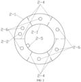
- the fluidized bed regenerator (2) includes a regenerator shell (2-1), a first gas-solid separation unit (2-2) of the regenerator, a first activation zone distributor (2-3), a baffle (2-4), a first activation zone catalyst delivery pipe (2-5), a first activation zone gas delivery pipe (2-6), a second activation zone distributor (2-7), a perforated plate (2-8), a fluidized bed regenerator cooler (2-9), a second gas-solid separation unit (2-10) of the regenerator, a regenerator gas collection chamber (2-11), a regenerator product gas delivery pipe (2-12), a regenerated catalyst inclined pipe (2-13), a regenerated catalyst slide valve (2-14), and a regenerated catalyst delivery pipe (2-15); the fluidized bed regenerator (2) is divided into a second activation zone, a first activation zone, and a gas-solid separation zone from bottom to top; the first activation zone is located in an annular zone above the second activation zone, n baffles (2-4) are arranged in the first activation zone
- the method for preparing light olefins from an oxygen-containing compound in the present application includes:
- the oxygen-containing compound is methanol;
- the spent catalyst zone fluidizing gas is nitrogen;
- the first activation zone raw material includes 10 wt% of oxygen and 90 wt% of water vapor;
- the second activation zone raw material is water vapor;
- an active component in the catalyst is an SAPO-34 molecular sieve;
- a coke content in the regenerated catalyst is about 5 wt%, where coke species include polymethylbenzene and polymethylnaphthalene, a mass of polymethylbenzene and polymethylnaphthalene accounts for about 72 wt% of a total mass of coke, a mass of coke species with a molecular weight greater than 184 accounts for about 19 wt% of a total mass of coke, and a quartile deviation of coke content distribution in the regenerated catalyst is about 0.9 wt%; a coke content in the spent catalyst is about 9 wt%;
- the reaction zone of the fluidized bed reactor (1) is a fast fluid
- the catalyst-to-alcohol ratio is about 0.3 ton of catalyst/ton of methanol;
- the product gas is composed of 55 wt% of ethylene, 37 wt% of propylene, 5 wt% of C 4 -C 6 hydrocarbon compounds, and 3 wt% of other components, where the other components include methane, ethane, propane, hydrogen, CO, CO 2 , and the like; and the unit consumption of production is 2.50 tons of methanol/ton of light olefins.
- the utilization rate of C atoms in the whole process is 99.0%.
- the oxygen-containing compound includes 82 wt% of methanol and 18 wt% of DME; the spent catalyst zone fluidizing gas is water vapor; the first activation zone raw material includes 20 wt% of air and 80 wt% of water vapor; the second activation zone raw material is water vapor; an active component in the catalyst is an SAPO-34 molecular sieve; a coke content in the regenerated catalyst is about 7 wt%, where coke species include polymethylbenzene and polymethylnaphthalene, a mass of polymethylbenzene and polymethylnaphthalene accounts for about 66 wt% of a total mass of coke, a mass of coke species with a molecular weight greater than 184 accounts for about 26 wt% of a total mass of coke, and a quartile deviation of coke content distribution in the regenerated catalyst is about 0.6 wt%; a coke content in the spent catalyst is about 11 wt%; process operating conditions of the
- the catalyst-to-alcohol ratio is about 0.5 ton of catalyst/ton of methanol;
- the product gas is composed of 38 wt% of ethylene, 54 wt% of propylene, 6 wt% of C 4 -C 6 hydrocarbon compounds, and 2 wt% of other components, where the other components include methane, ethane, propane, hydrogen, CO, CO 2 , and the like; and the unit consumption of production is 2.50 tons of methanol/ton of light olefins.
- the utilization rate of C atoms in the whole process is 99.3%.
- the oxygen-containing compound is DME;
- the spent catalyst zone fluidizing gas includes 5 wt% of nitrogen and 95 wt% of water vapor;
- the first activation zone raw material includes 1 wt% of oxygen and 99 wt% of water vapor;
- the second activation zone raw material is water vapor;
- an active component in the catalyst is an SAPO-34 molecular sieve;
- a coke content in the regenerated catalyst is about 9 wt%, where coke species include polymethylbenzene and polymethylnaphthalene, a mass of polymethylbenzene and polymethylnaphthalene accounts for about 79 wt% of a total mass of coke, a mass of coke species with a molecular weight greater than 184 accounts for about 13 wt% of a total mass of coke, and a quartile deviation of coke content distribution in the regenerated catalyst is about 0.2 wt%; a coke content in the spent catalyst is about 12 wt%; process
- the catalyst-to-alcohol ratio is about 0.8 ton of catalyst/ton of methanol;
- the product gas is composed of 45 wt% of ethylene, 51 wt% of propylene, 3 wt% of C 4 -C 6 hydrocarbon compounds, and 1 wt% of other components, where the other components include methane, ethane, propane, hydrogen, CO, CO 2 , and the like; and the unit consumption of production is 2.42 tons of methanol/ton of light olefins.
- the utilization rate of C atoms in the whole process is 99.5%.
- the oxygen-containing compound is methanol;
- the spent catalyst zone fluidizing gas is water vapor;
- the first activation zone raw material includes 5 wt% of air and 95 wt% of water vapor;
- the second activation zone raw material is water vapor;
- an active component in the catalyst is an SAPO-34 molecular sieve;
- a coke content in the regenerated catalyst is about 11 wt%, where coke species include polymethylbenzene and polymethylnaphthalene, a mass of polymethylbenzene and polymethylnaphthalene accounts for about 88 wt% of a total mass of coke, a mass of coke species with a molecular weight greater than 184 accounts for about 7 wt% of a total mass of coke, and a quartile deviation of coke content distribution in the regenerated catalyst is about 0.1 wt%; a coke content in the spent catalyst is about 13 wt%; process operating conditions of the reaction zone of the fluidized bed reactor (1)
- the catalyst-to-alcohol ratio is about 1.0 ton of catalyst/ton of methanol;
- the product gas is composed of 51 wt% of ethylene, 46 wt% of propylene, 2 wt% of C 4 -C 6 hydrocarbon compounds, and 1 wt% of other components, where the other components include methane, ethane, propane, hydrogen, CO, CO 2 , and the like; and the unit consumption of production is 2.40 tons of methanol/ton of light olefins.
- the utilization rate of C atoms in the whole process is 99.6%.
Landscapes
- Chemical & Material Sciences (AREA)
- Organic Chemistry (AREA)
- Engineering & Computer Science (AREA)
- Chemical Kinetics & Catalysis (AREA)
- Materials Engineering (AREA)
- Combustion & Propulsion (AREA)
- Organic Low-Molecular-Weight Compounds And Preparation Thereof (AREA)
- Devices And Processes Conducted In The Presence Of Fluids And Solid Particles (AREA)
- Catalysts (AREA)
- Low-Molecular Organic Synthesis Reactions Using Catalysts (AREA)
Claims (15)
- Régénérateur à lit fluidisé (2) destiné à activer un catalyseur pour préparer des oléfines légères à partir d'un composé contenant de l'oxygène, dans lequel le régénérateur à lit fluidisé comprend une première zone d'activation et une zone de séparation gaz-solide ; la première zone d'activation est une cavité annulaire ; n déflecteurs (2-4) sont disposés radialement dans la première zone d'activation, et les n déflecteurs divisent la première zone d'activation en n sous-zones de première zone d'activation ; et un trou d'écoulement de catalyseur est formé dans chacun de n-1 des déflecteurs, de telle sorte qu'un catalyseur entrant dans la première zone d'activation s'écoule dans une direction annulaire ; caractérisé en ce quele régénérateur à lit fluidisé comprend en outre une deuxième zone d'activation ; m plaques perforées (2-8) sont disposées horizontalement dans la deuxième zone d'activation, dans lequel 1 ≤ m ≤ 10 ;la deuxième zone d'activation, la première zone d'activation et la zone de séparation gaz-solide sont disposées du bas vers le haut ;la deuxième zone d'activation communique axialement avec la zone de séparation gaz-solide ; etla première zone d'activation est disposée sur une périphérie d'une jonction entre la deuxième zone d'activation et la zone de séparation gaz-solide.
- Régénérateur à lit fluidisé selon la revendication 1, dans lequel dans la première zone d'activation, les n déflecteurs comprennent un 1er déflecteur et un 2ème déflecteur à un n-ème déflecteur ;aucun trou d'écoulement de catalyseur n'est formé dans le 1er déflecteur ;un trou d'écoulement de catalyseur est formé dans chacun du 2ème déflecteur au n-ème déflecteur ;une entrée de catalyseur usé est formée dans une 1ère première sous-zone de zone d'activation formée par division par le 1er déflecteur et le 2ème déflecteur ;une conduite de distribution de catalyseur de première zone d'activation (2-5) est disposée dans une n-ème sous-zone de première zone d'activation formée par division par le 1er déflecteur et le n-ème déflecteur ;un distributeur de première zone d'activation (2-3) destiné à distribuer uniformément une matière première de première zone d'activation dans la première zone d'activation est disposé au-dessous des sous-zones de première zone d'activation ;une conduite de distribution de gaz de première zone d'activation (2-6) est disposée au niveau de parties supérieures des sous-zones de première zone d'activation.
- Régénérateur à lit fluidisé selon la revendication 1, dans lequel une première unité de séparation gaz-solide (2-2) du régénérateur est disposée dans une partie supérieure de la première zone d'activation ; et
la première unité de séparation gaz-solide du régénérateur communique avec la première zone d'activation à travers l'entrée de catalyseur usé. - Régénérateur à lit fluidisé selon la revendication 1, dans lequel n a une plage de valeurs de 2 ≤ n ≤10.
- Régénérateur à lit fluidisé selon la revendication 1, dans lequel une section transversale de chacune des sous-zones de la première zone d'activation est en secteurs annulaire.
- Régénérateur à lit fluidisé selon la revendication 1, dans lequel les plaques perforées (2-8) ont une porosité de 5% à 50%.
- Régénérateur à lit fluidisé selon la revendication 1, dans lequel un deuxième distributeur de zone d'activation (2-7) destiné à distribuer uniformément la matière première de deuxième zone d'activation dans la deuxième zone d'activation est disposé au fond de la deuxième zone d'activation.
- Régénérateur à lit fluidisé selon la revendication 1, dans lequel le régénérateur à lit fluidisé comprend une chambre de collecte de gaz de régénérateur et un refroidisseur de régénérateur à lit fluidisé ;la chambre de collecte de gaz régénérateur est située dans une partie supérieure du régénérateur à lit fluidisé ;une partie supérieure de la chambre de collecte de gaz régénérateur est pourvue d'une conduite de distribution de gaz produit de régénérateur ;la zone de séparation gaz-solide est pourvue d'une deuxième unité de séparation gaz-solide ; la chambre de collecte de gaz régénérateur est reliée à une sortie de la deuxième unité de séparation gaz-solide ; etle refroidisseur de régénérateur à lit fluidisé est situé dans une partie inférieure de la deuxième zone d'activation.
- Dispositif de préparation d'oléfines légères à partir d'un composé contenant de l'oxygène, comprenant un réacteur à lit fluidisé (1) et un régénérateur à lit fluidisé,
dans lequel le régénérateur à lit fluidisé comprend le régénérateur à lit fluidisé selon la revendication 1. - Dispositif selon la revendication 9, dans lequel le réacteur à lit fluidisé comprend une coque inférieure, une conduite de distribution (1-3) et une coque supérieure ;la coque inférieure renferme une zone de réaction ;la conduite de distribution est situé au-dessus de la zone de réaction et communique avec la zone de réaction ;la coque supérieure est disposée sur une périphérie de la conduite de distribution ;la coque supérieure et la conduite de distribution renferment une cavité ;la cavité est divisée en une zone de catalyseur usé et une zone de séparation gaz-solide du bas vers le haut.
- Dispositif selon la revendication 10, dans lequel la zone de catalyseur usé est une zone fluidisée bouillante.
- Dispositif selon la revendication 10, dans lequella zone de séparation gaz-solide est pourvue d'une première unité de séparation gaz-solide (1-4) du réacteur à lit fluidisé ;une partie supérieure de la conduite de distribution est reliée à une entrée de la première unité de séparation gaz-solide du réacteur à lit fluidisé.
- Dispositif selon la revendication 10, dans lequel le réacteur à lit fluidisé comprend un distributeur de réacteur à lit fluidisé (1-2), un refroidisseur de réacteur à lit fluidisé (1-7), un distributeur de gaz de zone de catalyseur usé (1-6), une chambre de collecte de gaz de réacteur à lit fluidisé (1-5), et une deuxième unité de séparation gaz-solide (1-8) du réacteur à lit fluidisé ;le distributeur de réacteur à lit fluidisé est situé au fond de la zone de réaction ;le refroidisseur de réacteur à lit fluidisé est situé dans une partie inférieure de la zone de catalyseur usé ;le distributeur de gaz de zone de catalyseur usé est situé dans la partie inférieure de la zone de catalyseur usé ;des sorties de gaz de la deuxième unité de séparation gaz-solide du réacteur à lit fluidisé et de la première unité de séparation gaz-solide du réacteur à lit fluidisé sont reliées à la chambre de collecte de gaz de réacteur à lit fluidisé ;la chambre de collecte de gaz de réacteur à lit fluidisé est pourvue d'une conduite de distribution de gaz produit (1-9) ; etdes sorties de catalyseur de la première unité de séparation gaz-solide du réacteur à lit fluidisé et de la deuxième unité de séparation gaz-solide du réacteur à lit fluidisé sont reliées à la zone de catalyseur usé.
- Procédé d'activation d'un catalyseur pour préparer des oléfines légères à partir d'un composé contenant de l'oxygène, en utilisant le régénérateur à lit fluidisé selon l'une quelconque des revendications 1 à 8,
dans lequel le procédé comprend :introduire une matière première de première zone d'activation et un catalyseur usé dans la première zone d'activation, dans lequel le catalyseur usé réagit chimiquement avec la matière première de première zone d'activation tout en s'écoulant dans une direction annulaire le long des sous-zones de la première zone d'activation pour générer un catalyseur partiellement activé ; etintroduire le catalyseur partiellement activé et une matière première de deuxième zone d'activation dans la deuxième zone d'activation, et permettre une réaction chimique pour générer un catalyseur régénéré ;dans lequel une composition de coke dans le catalyseur partiellement activé comprend des espèces hydrocarbonées contenant de l'oxygène et des espèces hydrocarbonées sans oxygène. - Procédé de préparation d'oléfines légères à partir d'un composé contenant de l'oxygène en utilisant le dispositif selon la revendication 9,
dans lequel le procédé comprend :introduire une matière première avec le composé contenant de l'oxygène et un catalyseur régénéré dans la zone de réaction, et permettre une réaction pour obtenir un courant A avec des oléfines légères et un catalyseur usé ;soumettre le courant A à une séparation gaz-solide, et acheminer le catalyseur usé vers la zone de catalyseur usé ; etrenvoyer une partie du catalyseur usé dans la zone de catalyseur usé vers une zone de réaction à lit fluidisé, et permettre à la partie restante du catalyseur usé d'entrer dans le régénérateur à lit fluidisé.
Applications Claiming Priority (1)
| Application Number | Priority Date | Filing Date | Title |
|---|---|---|---|
| PCT/CN2020/121577 WO2022077460A1 (fr) | 2020-10-16 | 2020-10-16 | Régénérateur à lit fluidisé, appareil pour préparer une oléfine à faible teneur en carbone et application de celui-ci |
Publications (3)
| Publication Number | Publication Date |
|---|---|
| EP4082655A1 EP4082655A1 (fr) | 2022-11-02 |
| EP4082655A4 EP4082655A4 (fr) | 2023-04-26 |
| EP4082655B1 true EP4082655B1 (fr) | 2025-01-01 |
Family
ID=81208865
Family Applications (1)
| Application Number | Title | Priority Date | Filing Date |
|---|---|---|---|
| EP20957238.7A Active EP4082655B1 (fr) | 2020-10-16 | 2020-10-16 | Régénérateur à lit fluidisé, appareil pour préparer une oléfine à faible teneur en carbone et application de celui-ci |
Country Status (5)
| Country | Link |
|---|---|
| US (1) | US12296329B2 (fr) |
| EP (1) | EP4082655B1 (fr) |
| JP (1) | JP7449415B2 (fr) |
| KR (1) | KR102803676B1 (fr) |
| WO (1) | WO2022077460A1 (fr) |
Families Citing this family (3)
| Publication number | Priority date | Publication date | Assignee | Title |
|---|---|---|---|---|
| WO2024173638A1 (fr) * | 2023-02-17 | 2024-08-22 | ExxonMobil Technology and Engineering Company | Procédé intégré et système de formation d'hydrocarbures |
| CN116426310B (zh) * | 2023-04-25 | 2025-11-11 | 中国石油大学(北京) | 具有导流结构的再生器 |
| CN120169264A (zh) * | 2023-12-19 | 2025-06-20 | 中国科学院大连化学物理研究所 | 一种高密度快速流化床反应器及其使用方法 |
Family Cites Families (23)
| Publication number | Priority date | Publication date | Assignee | Title |
|---|---|---|---|---|
| GR59847B (en) * | 1975-03-24 | 1978-03-07 | Ashland Oil Inc | Method and apparatus for disengaging particles from gases |
| IT1134169B (it) * | 1979-11-06 | 1986-07-31 | Escher Wyss Sa | Dispositivo a letto fluido |
| US4397738A (en) * | 1982-09-16 | 1983-08-09 | Uop Inc. | Process for the separation of particulate solids from vapors |
| US4851374A (en) * | 1987-05-29 | 1989-07-25 | Mobil Oil Corporation | Apparatus and method for regenerating coked fluid cracking catalyst |
| US6437208B1 (en) | 1999-09-29 | 2002-08-20 | Exxonmobil Chemical Patents Inc. | Making an olefin product from an oxygenate |
| US6673978B2 (en) | 2001-05-11 | 2004-01-06 | Exxonmobil Chemical Patents Inc. | Process for making olefins |
| US7227048B2 (en) | 2001-12-31 | 2007-06-05 | Exxonmobil Chemical Patents Inc. | Converting oxygenates to olefins over a catalyst comprising acidic molecular sieve of controlled carbon atom to acid site ratio |
| US7273960B2 (en) * | 2002-10-25 | 2007-09-25 | Exxonmobil Chemical Patents Inc | Fluid bed oxygenates to olefins reactor apparatus and process of controlling same |
| US7179427B2 (en) | 2002-11-25 | 2007-02-20 | Abb Lummus Global Inc. | Apparatus for countercurrent contacting of gas and solids |
| US7763766B2 (en) | 2005-12-22 | 2010-07-27 | Uop Llc | Methanol-to-olefins process with reduced coking |
| EP2070592A3 (fr) | 2007-12-05 | 2012-01-18 | Uop Llc | Appareil et procédé pour régénérer un catalyseur |
| RU2529021C2 (ru) | 2009-03-31 | 2014-09-27 | Чайна Петролеум & Кемикал Корпорейшн | Способ регенерации катализатора |
| CN102463138B (zh) | 2010-11-17 | 2013-08-14 | 中国石油化工股份有限公司 | Sapo-34催化剂的两段再生方法 |
| EP2785459A1 (fr) | 2011-11-28 | 2014-10-08 | Shell Internationale Research Maatschappij B.V. | Procédé de régénération oxydative d'un catalyseur désactivé et appareil pour réaliser ce procédé |
| CN104419468A (zh) | 2013-08-30 | 2015-03-18 | 中国石油化工股份有限公司 | 一种待生剂上焦炭气化方法 |
| CN104672044B (zh) | 2013-12-03 | 2016-06-08 | 中国科学院大连化学物理研究所 | 一种含氧化合物制低碳烯烃的方法 |
| CN104672040B (zh) | 2013-12-03 | 2017-06-16 | 中国科学院大连化学物理研究所 | 一种含氧化合物制低碳烯烃的方法及其使用的设备 |
| BR112016012633B1 (pt) | 2013-12-03 | 2021-07-20 | Dalian Institute Of Chemical Physics, Chinese Academy Of Sciences | Método para preparar uma olefina leve com um composto que contém oxigênio |
| CN107540492A (zh) | 2016-06-29 | 2018-01-05 | 中国石油化工股份有限公司 | 由甲醇或二甲醚生产芳烃和低碳烯烃的方法 |
| CN107540494A (zh) | 2016-06-29 | 2018-01-05 | 中国石油化工股份有限公司 | 甲醇或二甲醚制备芳烃和低碳烯烃的方法 |
| CN107963957B (zh) | 2016-10-19 | 2022-01-25 | 中国科学院大连化学物理研究所 | 一种制备丙烯和c4烃类的方法及其装置 |
| CN107961743B (zh) | 2016-10-19 | 2021-12-31 | 中国科学院大连化学物理研究所 | 一种由含氧化合物制备丙烯、c4烃类的快速流化床反应器、装置及方法 |
| CN106732823A (zh) | 2016-11-16 | 2017-05-31 | 青岛京润石化设计研究院有限公司 | 一种流化床催化剂再生方法 |
-
2020
- 2020-10-16 EP EP20957238.7A patent/EP4082655B1/fr active Active
- 2020-10-16 KR KR1020227043991A patent/KR102803676B1/ko active Active
- 2020-10-16 WO PCT/CN2020/121577 patent/WO2022077460A1/fr not_active Ceased
- 2020-10-16 US US17/777,052 patent/US12296329B2/en active Active
- 2020-10-16 JP JP2022573395A patent/JP7449415B2/ja active Active
Also Published As
| Publication number | Publication date |
|---|---|
| JP2023530853A (ja) | 2023-07-20 |
| EP4082655A4 (fr) | 2023-04-26 |
| EP4082655A1 (fr) | 2022-11-02 |
| US12296329B2 (en) | 2025-05-13 |
| KR20230013254A (ko) | 2023-01-26 |
| WO2022077460A1 (fr) | 2022-04-21 |
| KR102803676B1 (ko) | 2025-05-07 |
| JP7449415B2 (ja) | 2024-03-13 |
| US20220401905A1 (en) | 2022-12-22 |
Similar Documents
| Publication | Publication Date | Title |
|---|---|---|
| KR101847474B1 (ko) | 산소 함유 화합물을 사용하여 저급 올레핀을 제조하는 방법 | |
| US12296329B2 (en) | Fluidized bed regenerator, device for preparing low-carbon olefins, and use thereof | |
| CN114377620B (zh) | 流化床反应器、装置以及含氧化合物制备低碳烯烃的方法 | |
| CN114377729B (zh) | 流化床再生器、制备低碳烯烃的装置及其应用 | |
| US12296324B2 (en) | Regeneration device, device for preparing low-carbon olefins, and use thereof | |
| EP4082658B1 (fr) | Réacteur de contrôle de coke, dispositif de préparation d'oléfines à faible teneur en carbone à partir d'un composé contenant de l'oxygène et son utilisation | |
| CN114377730B (zh) | 再生装置、制备低碳烯烃的装置及其应用 | |
| EP4082654B1 (fr) | Réacteur à lit fluidisé, appareil et procédé de préparation d'oléfine à faible teneur en carbone à partir d'un composé contenant de l'oxygène | |
| RU2807509C1 (ru) | Регенератор с псевдоожиженным слоем, устройство для получения низкоуглеродистых олефинов и их применение | |
| RU2815512C1 (ru) | Устройство для регенерации, устройство для получения низкоуглеродистых олефинов и их применение | |
| EP4105193B1 (fr) | Procédé de régulation et de contrôle de coke pour la préparation d'oléfine légère à partir d'un composé contenant de l'oxygène | |
| EP4088811B1 (fr) | Réacteur à lit fluidisé, dispositif et application | |
| RU2812664C1 (ru) | Реактор для управления содержанием кокса, устройство для получения низкоуглеродистых олефинов из кислородсодержащего соединения и их применение | |
| RU2810794C1 (ru) | Реактор с псевдоожиженным слоем, устройство и их применение | |
| RU2798851C1 (ru) | Реактор для управления содержанием кокса, а также устройство и способ получения низкоуглеродистых олефинов из кислородсодержащего соединения | |
| CN114377624A (zh) | 一种焦调控反应器、由含氧化合物制备低碳烯烃的装置和应用 | |
| CN114377625A (zh) | 焦调控反应器、装置及含氧化合物制备低碳烯烃的方法 |
Legal Events
| Date | Code | Title | Description |
|---|---|---|---|
| STAA | Information on the status of an ep patent application or granted ep patent |
Free format text: STATUS: THE INTERNATIONAL PUBLICATION HAS BEEN MADE |
|
| PUAI | Public reference made under article 153(3) epc to a published international application that has entered the european phase |
Free format text: ORIGINAL CODE: 0009012 |
|
| STAA | Information on the status of an ep patent application or granted ep patent |
Free format text: STATUS: REQUEST FOR EXAMINATION WAS MADE |
|
| 17P | Request for examination filed |
Effective date: 20220727 |
|
| AK | Designated contracting states |
Kind code of ref document: A1 Designated state(s): AL AT BE BG CH CY CZ DE DK EE ES FI FR GB GR HR HU IE IS IT LI LT LU LV MC MK MT NL NO PL PT RO RS SE SI SK SM TR |
|
| A4 | Supplementary search report drawn up and despatched |
Effective date: 20230327 |
|
| RIC1 | Information provided on ipc code assigned before grant |
Ipc: B01J 38/14 20060101ALI20230321BHEP Ipc: B01J 38/06 20060101ALI20230321BHEP Ipc: B01J 8/26 20060101ALI20230321BHEP Ipc: C07C 4/06 20060101ALI20230321BHEP Ipc: C07C 11/02 20060101ALI20230321BHEP Ipc: C07C 1/20 20060101ALI20230321BHEP Ipc: B01J 38/16 20060101ALI20230321BHEP Ipc: B01J 29/90 20060101ALI20230321BHEP Ipc: B01J 8/24 20060101AFI20230321BHEP |
|
| STAA | Information on the status of an ep patent application or granted ep patent |
Free format text: STATUS: EXAMINATION IS IN PROGRESS |
|
| 17Q | First examination report despatched |
Effective date: 20230908 |
|
| DAV | Request for validation of the european patent (deleted) | ||
| DAX | Request for extension of the european patent (deleted) | ||
| GRAP | Despatch of communication of intention to grant a patent |
Free format text: ORIGINAL CODE: EPIDOSNIGR1 |
|
| STAA | Information on the status of an ep patent application or granted ep patent |
Free format text: STATUS: GRANT OF PATENT IS INTENDED |
|
| INTG | Intention to grant announced |
Effective date: 20240620 |
|
| GRAJ | Information related to disapproval of communication of intention to grant by the applicant or resumption of examination proceedings by the epo deleted |
Free format text: ORIGINAL CODE: EPIDOSDIGR1 |
|
| STAA | Information on the status of an ep patent application or granted ep patent |
Free format text: STATUS: EXAMINATION IS IN PROGRESS |
|
| GRAP | Despatch of communication of intention to grant a patent |
Free format text: ORIGINAL CODE: EPIDOSNIGR1 |
|
| STAA | Information on the status of an ep patent application or granted ep patent |
Free format text: STATUS: GRANT OF PATENT IS INTENDED |
|
| INTC | Intention to grant announced (deleted) | ||
| INTG | Intention to grant announced |
Effective date: 20240819 |
|
| GRAS | Grant fee paid |
Free format text: ORIGINAL CODE: EPIDOSNIGR3 |
|
| GRAA | (expected) grant |
Free format text: ORIGINAL CODE: 0009210 |
|
| STAA | Information on the status of an ep patent application or granted ep patent |
Free format text: STATUS: THE PATENT HAS BEEN GRANTED |
|
| AK | Designated contracting states |
Kind code of ref document: B1 Designated state(s): AL AT BE BG CH CY CZ DE DK EE ES FI FR GB GR HR HU IE IS IT LI LT LU LV MC MK MT NL NO PL PT RO RS SE SI SK SM TR |
|
| REG | Reference to a national code |
Ref country code: GB Ref legal event code: FG4D |
|
| REG | Reference to a national code |
Ref country code: DE Ref legal event code: R096 Ref document number: 602020044360 Country of ref document: DE |
|
| REG | Reference to a national code |
Ref country code: CH Ref legal event code: EP |
|
| REG | Reference to a national code |
Ref country code: IE Ref legal event code: FG4D |
|
| P01 | Opt-out of the competence of the unified patent court (upc) registered |
Free format text: CASE NUMBER: APP_185/2025 Effective date: 20250103 |
|
| REG | Reference to a national code |
Ref country code: LT Ref legal event code: MG9D |
|
| REG | Reference to a national code |
Ref country code: NL Ref legal event code: MP Effective date: 20250101 |
|
| REG | Reference to a national code |
Ref country code: AT Ref legal event code: MK05 Ref document number: 1755679 Country of ref document: AT Kind code of ref document: T Effective date: 20250101 |
|
| PG25 | Lapsed in a contracting state [announced via postgrant information from national office to epo] |
Ref country code: NL Free format text: LAPSE BECAUSE OF FAILURE TO SUBMIT A TRANSLATION OF THE DESCRIPTION OR TO PAY THE FEE WITHIN THE PRESCRIBED TIME-LIMIT Effective date: 20250101 |
|
| PG25 | Lapsed in a contracting state [announced via postgrant information from national office to epo] |
Ref country code: FI Free format text: LAPSE BECAUSE OF FAILURE TO SUBMIT A TRANSLATION OF THE DESCRIPTION OR TO PAY THE FEE WITHIN THE PRESCRIBED TIME-LIMIT Effective date: 20250101 |
|
| PG25 | Lapsed in a contracting state [announced via postgrant information from national office to epo] |
Ref country code: PL Free format text: LAPSE BECAUSE OF FAILURE TO SUBMIT A TRANSLATION OF THE DESCRIPTION OR TO PAY THE FEE WITHIN THE PRESCRIBED TIME-LIMIT Effective date: 20250101 |
|
| PG25 | Lapsed in a contracting state [announced via postgrant information from national office to epo] |
Ref country code: ES Free format text: LAPSE BECAUSE OF FAILURE TO SUBMIT A TRANSLATION OF THE DESCRIPTION OR TO PAY THE FEE WITHIN THE PRESCRIBED TIME-LIMIT Effective date: 20250101 |
|
| PG25 | Lapsed in a contracting state [announced via postgrant information from national office to epo] |
Ref country code: NO Free format text: LAPSE BECAUSE OF FAILURE TO SUBMIT A TRANSLATION OF THE DESCRIPTION OR TO PAY THE FEE WITHIN THE PRESCRIBED TIME-LIMIT Effective date: 20250401 Ref country code: IS Free format text: LAPSE BECAUSE OF FAILURE TO SUBMIT A TRANSLATION OF THE DESCRIPTION OR TO PAY THE FEE WITHIN THE PRESCRIBED TIME-LIMIT Effective date: 20250501 |
|
| PG25 | Lapsed in a contracting state [announced via postgrant information from national office to epo] |
Ref country code: HR Free format text: LAPSE BECAUSE OF FAILURE TO SUBMIT A TRANSLATION OF THE DESCRIPTION OR TO PAY THE FEE WITHIN THE PRESCRIBED TIME-LIMIT Effective date: 20250101 |
|
| PG25 | Lapsed in a contracting state [announced via postgrant information from national office to epo] |
Ref country code: LV Free format text: LAPSE BECAUSE OF FAILURE TO SUBMIT A TRANSLATION OF THE DESCRIPTION OR TO PAY THE FEE WITHIN THE PRESCRIBED TIME-LIMIT Effective date: 20250101 Ref country code: PT Free format text: LAPSE BECAUSE OF FAILURE TO SUBMIT A TRANSLATION OF THE DESCRIPTION OR TO PAY THE FEE WITHIN THE PRESCRIBED TIME-LIMIT Effective date: 20250502 |
|
| PG25 | Lapsed in a contracting state [announced via postgrant information from national office to epo] |
Ref country code: GR Free format text: LAPSE BECAUSE OF FAILURE TO SUBMIT A TRANSLATION OF THE DESCRIPTION OR TO PAY THE FEE WITHIN THE PRESCRIBED TIME-LIMIT Effective date: 20250402 Ref country code: BG Free format text: LAPSE BECAUSE OF FAILURE TO SUBMIT A TRANSLATION OF THE DESCRIPTION OR TO PAY THE FEE WITHIN THE PRESCRIBED TIME-LIMIT Effective date: 20250101 |
|
| PG25 | Lapsed in a contracting state [announced via postgrant information from national office to epo] |
Ref country code: AT Free format text: LAPSE BECAUSE OF FAILURE TO SUBMIT A TRANSLATION OF THE DESCRIPTION OR TO PAY THE FEE WITHIN THE PRESCRIBED TIME-LIMIT Effective date: 20250101 |
|
| PG25 | Lapsed in a contracting state [announced via postgrant information from national office to epo] |
Ref country code: CZ Free format text: LAPSE BECAUSE OF FAILURE TO SUBMIT A TRANSLATION OF THE DESCRIPTION OR TO PAY THE FEE WITHIN THE PRESCRIBED TIME-LIMIT Effective date: 20250101 |
|
| PG25 | Lapsed in a contracting state [announced via postgrant information from national office to epo] |
Ref country code: SE Free format text: LAPSE BECAUSE OF FAILURE TO SUBMIT A TRANSLATION OF THE DESCRIPTION OR TO PAY THE FEE WITHIN THE PRESCRIBED TIME-LIMIT Effective date: 20250101 |
|
| REG | Reference to a national code |
Ref country code: DE Ref legal event code: R097 Ref document number: 602020044360 Country of ref document: DE |
|
| PG25 | Lapsed in a contracting state [announced via postgrant information from national office to epo] |
Ref country code: SM Free format text: LAPSE BECAUSE OF FAILURE TO SUBMIT A TRANSLATION OF THE DESCRIPTION OR TO PAY THE FEE WITHIN THE PRESCRIBED TIME-LIMIT Effective date: 20250101 |
|
| PG25 | Lapsed in a contracting state [announced via postgrant information from national office to epo] |
Ref country code: DK Free format text: LAPSE BECAUSE OF FAILURE TO SUBMIT A TRANSLATION OF THE DESCRIPTION OR TO PAY THE FEE WITHIN THE PRESCRIBED TIME-LIMIT Effective date: 20250101 |
|
| PG25 | Lapsed in a contracting state [announced via postgrant information from national office to epo] |
Ref country code: IT Free format text: LAPSE BECAUSE OF FAILURE TO SUBMIT A TRANSLATION OF THE DESCRIPTION OR TO PAY THE FEE WITHIN THE PRESCRIBED TIME-LIMIT Effective date: 20250101 |
|
| PG25 | Lapsed in a contracting state [announced via postgrant information from national office to epo] |
Ref country code: EE Free format text: LAPSE BECAUSE OF FAILURE TO SUBMIT A TRANSLATION OF THE DESCRIPTION OR TO PAY THE FEE WITHIN THE PRESCRIBED TIME-LIMIT Effective date: 20250101 |
|
| PG25 | Lapsed in a contracting state [announced via postgrant information from national office to epo] |
Ref country code: RO Free format text: LAPSE BECAUSE OF FAILURE TO SUBMIT A TRANSLATION OF THE DESCRIPTION OR TO PAY THE FEE WITHIN THE PRESCRIBED TIME-LIMIT Effective date: 20250101 |
|
| PG25 | Lapsed in a contracting state [announced via postgrant information from national office to epo] |
Ref country code: SK Free format text: LAPSE BECAUSE OF FAILURE TO SUBMIT A TRANSLATION OF THE DESCRIPTION OR TO PAY THE FEE WITHIN THE PRESCRIBED TIME-LIMIT Effective date: 20250101 |
|
| PLBE | No opposition filed within time limit |
Free format text: ORIGINAL CODE: 0009261 |
|
| STAA | Information on the status of an ep patent application or granted ep patent |
Free format text: STATUS: NO OPPOSITION FILED WITHIN TIME LIMIT |
|
| 26N | No opposition filed |
Effective date: 20251002 |