EP4082700A1 - Procédé de fabrication d'un outil de coupe - Google Patents
Procédé de fabrication d'un outil de coupe Download PDFInfo
- Publication number
- EP4082700A1 EP4082700A1 EP21750939.7A EP21750939A EP4082700A1 EP 4082700 A1 EP4082700 A1 EP 4082700A1 EP 21750939 A EP21750939 A EP 21750939A EP 4082700 A1 EP4082700 A1 EP 4082700A1
- Authority
- EP
- European Patent Office
- Prior art keywords
- hard coating
- cutting edge
- residual stress
- cutting
- tool body
- Prior art date
- Legal status (The legal status is an assumption and is not a legal conclusion. Google has not performed a legal analysis and makes no representation as to the accuracy of the status listed.)
- Pending
Links
Images
Classifications
-
- B—PERFORMING OPERATIONS; TRANSPORTING
- B23—MACHINE TOOLS; METAL-WORKING NOT OTHERWISE PROVIDED FOR
- B23K—SOLDERING OR UNSOLDERING; WELDING; CLADDING OR PLATING BY SOLDERING OR WELDING; CUTTING BY APPLYING HEAT LOCALLY, e.g. FLAME CUTTING; WORKING BY LASER BEAM
- B23K26/00—Working by laser beam, e.g. welding, cutting or boring
- B23K26/352—Working by laser beam, e.g. welding, cutting or boring for surface treatment
- B23K26/356—Working by laser beam, e.g. welding, cutting or boring for surface treatment by shock processing
-
- B—PERFORMING OPERATIONS; TRANSPORTING
- B23—MACHINE TOOLS; METAL-WORKING NOT OTHERWISE PROVIDED FOR
- B23B—TURNING; BORING
- B23B27/00—Tools for turning or boring machines; Tools of a similar kind in general; Accessories therefor
- B23B27/14—Cutting tools of which the bits or tips or cutting inserts are of special material
- B23B27/141—Specially shaped plate-like cutting inserts, i.e. length greater or equal to width, width greater than or equal to thickness
-
- B—PERFORMING OPERATIONS; TRANSPORTING
- B23—MACHINE TOOLS; METAL-WORKING NOT OTHERWISE PROVIDED FOR
- B23K—SOLDERING OR UNSOLDERING; WELDING; CLADDING OR PLATING BY SOLDERING OR WELDING; CUTTING BY APPLYING HEAT LOCALLY, e.g. FLAME CUTTING; WORKING BY LASER BEAM
- B23K26/00—Working by laser beam, e.g. welding, cutting or boring
- B23K26/0006—Working by laser beam, e.g. welding, cutting or boring taking account of the properties of the material involved
-
- B—PERFORMING OPERATIONS; TRANSPORTING
- B23—MACHINE TOOLS; METAL-WORKING NOT OTHERWISE PROVIDED FOR
- B23K—SOLDERING OR UNSOLDERING; WELDING; CLADDING OR PLATING BY SOLDERING OR WELDING; CUTTING BY APPLYING HEAT LOCALLY, e.g. FLAME CUTTING; WORKING BY LASER BEAM
- B23K26/00—Working by laser beam, e.g. welding, cutting or boring
- B23K26/02—Positioning or observing the workpiece, e.g. with respect to the point of impact; Aligning, aiming or focusing the laser beam
- B23K26/06—Shaping the laser beam, e.g. by masks or multi-focusing
- B23K26/062—Shaping the laser beam, e.g. by masks or multi-focusing by direct control of the laser beam
- B23K26/0622—Shaping the laser beam, e.g. by masks or multi-focusing by direct control of the laser beam by shaping pulses
-
- B—PERFORMING OPERATIONS; TRANSPORTING
- B23—MACHINE TOOLS; METAL-WORKING NOT OTHERWISE PROVIDED FOR
- B23K—SOLDERING OR UNSOLDERING; WELDING; CLADDING OR PLATING BY SOLDERING OR WELDING; CUTTING BY APPLYING HEAT LOCALLY, e.g. FLAME CUTTING; WORKING BY LASER BEAM
- B23K26/00—Working by laser beam, e.g. welding, cutting or boring
- B23K26/02—Positioning or observing the workpiece, e.g. with respect to the point of impact; Aligning, aiming or focusing the laser beam
- B23K26/06—Shaping the laser beam, e.g. by masks or multi-focusing
- B23K26/062—Shaping the laser beam, e.g. by masks or multi-focusing by direct control of the laser beam
- B23K26/0622—Shaping the laser beam, e.g. by masks or multi-focusing by direct control of the laser beam by shaping pulses
- B23K26/0624—Shaping the laser beam, e.g. by masks or multi-focusing by direct control of the laser beam by shaping pulses using ultrashort pulses, i.e. pulses of 1 ns or less
-
- B—PERFORMING OPERATIONS; TRANSPORTING
- B23—MACHINE TOOLS; METAL-WORKING NOT OTHERWISE PROVIDED FOR
- B23K—SOLDERING OR UNSOLDERING; WELDING; CLADDING OR PLATING BY SOLDERING OR WELDING; CUTTING BY APPLYING HEAT LOCALLY, e.g. FLAME CUTTING; WORKING BY LASER BEAM
- B23K26/00—Working by laser beam, e.g. welding, cutting or boring
- B23K26/50—Working by transmitting the laser beam through or within the workpiece
- B23K26/53—Working by transmitting the laser beam through or within the workpiece for modifying or reforming the material inside the workpiece, e.g. for producing break initiation cracks
-
- C—CHEMISTRY; METALLURGY
- C21—METALLURGY OF IRON
- C21D—MODIFYING THE PHYSICAL STRUCTURE OF FERROUS METALS; GENERAL DEVICES FOR HEAT TREATMENT OF FERROUS OR NON-FERROUS METALS OR ALLOYS; MAKING METAL MALLEABLE, e.g. BY DECARBURISATION OR TEMPERING
- C21D10/00—Modifying the physical properties by methods other than heat treatment or deformation
- C21D10/005—Modifying the physical properties by methods other than heat treatment or deformation by laser shock processing
-
- B—PERFORMING OPERATIONS; TRANSPORTING
- B23—MACHINE TOOLS; METAL-WORKING NOT OTHERWISE PROVIDED FOR
- B23B—TURNING; BORING
- B23B2200/00—Details of cutting inserts
- B23B2200/16—Supporting or bottom surfaces
- B23B2200/166—Supporting or bottom surfaces polygonal
-
- B—PERFORMING OPERATIONS; TRANSPORTING
- B23—MACHINE TOOLS; METAL-WORKING NOT OTHERWISE PROVIDED FOR
- B23B—TURNING; BORING
- B23B2222/00—Materials of tools or workpieces composed of metals, alloys or metal matrices
- B23B2222/28—Details of hard metal, i.e. cemented carbide
-
- B—PERFORMING OPERATIONS; TRANSPORTING
- B23—MACHINE TOOLS; METAL-WORKING NOT OTHERWISE PROVIDED FOR
- B23B—TURNING; BORING
- B23B2228/00—Properties of materials of tools or workpieces, materials of tools or workpieces applied in a specific manner
- B23B2228/10—Coatings
-
- B—PERFORMING OPERATIONS; TRANSPORTING
- B23—MACHINE TOOLS; METAL-WORKING NOT OTHERWISE PROVIDED FOR
- B23B—TURNING; BORING
- B23B27/00—Tools for turning or boring machines; Tools of a similar kind in general; Accessories therefor
- B23B27/14—Cutting tools of which the bits or tips or cutting inserts are of special material
-
- B—PERFORMING OPERATIONS; TRANSPORTING
- B23—MACHINE TOOLS; METAL-WORKING NOT OTHERWISE PROVIDED FOR
- B23K—SOLDERING OR UNSOLDERING; WELDING; CLADDING OR PLATING BY SOLDERING OR WELDING; CUTTING BY APPLYING HEAT LOCALLY, e.g. FLAME CUTTING; WORKING BY LASER BEAM
- B23K2101/00—Articles made by soldering, welding or cutting
- B23K2101/20—Tools
-
- B—PERFORMING OPERATIONS; TRANSPORTING
- B23—MACHINE TOOLS; METAL-WORKING NOT OTHERWISE PROVIDED FOR
- B23K—SOLDERING OR UNSOLDERING; WELDING; CLADDING OR PLATING BY SOLDERING OR WELDING; CUTTING BY APPLYING HEAT LOCALLY, e.g. FLAME CUTTING; WORKING BY LASER BEAM
- B23K2103/00—Materials to be soldered, welded or cut
- B23K2103/16—Composite materials
- B23K2103/166—Multilayered materials
- B23K2103/172—Multilayered materials wherein at least one of the layers is non-metallic
-
- B—PERFORMING OPERATIONS; TRANSPORTING
- B23—MACHINE TOOLS; METAL-WORKING NOT OTHERWISE PROVIDED FOR
- B23K—SOLDERING OR UNSOLDERING; WELDING; CLADDING OR PLATING BY SOLDERING OR WELDING; CUTTING BY APPLYING HEAT LOCALLY, e.g. FLAME CUTTING; WORKING BY LASER BEAM
- B23K2103/00—Materials to be soldered, welded or cut
- B23K2103/50—Inorganic materials other than metals or composite materials
Definitions
- the present invention relates to a method for manufacturing a cutting tool, and more particularly to a post-treatment method for improving the fracture resistance of a cutting edge of a cutting tool.
- Patent Document 1 discloses a method of controlling residual stress by an impact force generated by allowing submillimeter-order steel balls to collide with a tool surface in shot peening.
- Patent Document 2 discloses a surface treatment method of irradiating a nanosecond laser to reduce the tensile stress of a TiCN hard coating or to apply compressive stress.
- Patent Document 4 discloses a method of applying compressive residual stress to a base material made of cemented carbide by performing so-called nanosecond laser peening using a high-energy nanosecond laser having a pulse width of about several ns and a pulse energy of several hundred mJ.
- the compressive residual stress of a hard phase of a hard coating or the surface layer of the tool body can be increased by adjusting the material and size of the media, or by increasing the projecting pressure and projecting time of shot peening.
- the vertical crack is a crack that divides the hard coating or the surface layer of the tool body, and a gap having a width of about several hundred nm is generated.
- an oxide layer (Al 2 O 3 ) which is an upper layer of the hard coating is removed by using the nanosecond laser, and a compressive residual stress of up to about 1 GPa is applied to a non-oxide layer (TiCN) which is a lower layer of the hard coating.
- This mechanism is not mentioned in the specification of Patent Document 2, but is considered to be a kind of so-called laser peening because the lower layer is impacted by the mechanical reaction that occurs when the oxide layer is instantaneously removed in a time on the order of nanoseconds and the oxide layer is scattered by fine particles, plasma, or the like.
- a compressive residual stress of about 1 GPa can be applied to the lower layer (TiCN) at a peak power density (0.02 GW/cm 2 ) close to the lower limit at which the oxide layer can be removed.
- the compressive residual stress of the lower layer is conversely decreased. It is considered that the reason for this is that the compressive residual stress is released by the effect of heat due to the excessive laser beam hitting the lower layer.
- the effect of applying compressive residual stress to the surface layer of the tool body immediately under the hard coating can hardly be obtained. That is, the fracture resistance of the tool body cannot be improved.
- Patent Document 3 although a difference is provided between the residual stress value in the direction orthogonal to the ridge portion of the cutting edge made of ⁇ -Al 2 O 3 and the residual stress value in the direction parallel to the ridge portion of the cutting edge by the shot peening, the media are uniformly projected against the rake face during the shot peening, so that it is difficult to stably apply a large residual stress difference.
- an object of the present invention is to provide a method for manufacturing a cutting tool in which a high compressive residual stress can be stably applied to a hard coating and a tool body, thereby improving the fracture resistance of a cutting edge.
- a method for manufacturing a cutting tool in which the cutting tool includes a tool body made of a sintered alloy, a hard coating which is disposed on an outer surface of the tool body and has at least a layer formed of any of a carbide, a nitride, and a carbonitride, or a composite compound thereof, and a cutting edge which is formed at a ridge portion of the tool body and includes a portion of the hard coating located at the ridge portion, the method including: a laser peening step of directly irradiating the hard coating with a pulsed laser having a pulse width of 100 ps or less to apply compressive residual stress to the hard coating and a surface region of the tool body.
- the cutting tool in which the hard coating is formed on the outer surface of the tool body is irradiated with a short pulsed laser having a pulse width of 100 ps (picosecond) or less at a peak power density of desirably 1 TW (terawatt)/cm 2 or more, for example, in the air from above the hard coating.
- This treatment is so-called ultrashort pulsed laser peening, and is a technique of applying compressive residual stress to the surface of a workpiece (cutting tool) by generating a shock wave in the workpiece by the mechanical reaction that occurs when a plasma generated by slightly processing the surface of the workpiece subjected to laser irradiation is explosively diffused, and thus applying plastic deformation and crystal defects such as dislocations.
- by performing the laser peening under the above laser conditions it is possible to stably apply compressive residual stress while suppressing the occurrence of vertical cracks in the hard coating and the tool body.
- the pulse width is 100 ps or less, the effect of heat due to the laser irradiation is significantly suppressed, so that the peak power density, that is, the energy of the shock wave can be increased.
- a residual stress of 0 or less to the layer (the layer formed of any of a carbide, a nitride, and a carbonitride, or a composite compound thereof) contributing to the fracture resistance of the hard coating, and -1000 MPa or less to WC particles of the surface region of the tool body, that is, a compressive residual stress can be applied.
- a high compressive residual stress can be applied to both the hard coating and the tool body while suppressing the occurrence of vertical cracks by the laser peening step under the special laser conditions. Accordingly, the fracture resistance of the cutting edge can be improved. Good cutting accuracy is maintained and the tool life is extended.
- the compressive residual stress can be stably applied, variation in the quality of the cutting tool can be suppressed.
- the laser irradiation can be performed in the air and pre- and post-treatment steps are not particularly required, compared to a generally known stress control technique such as wet blasting, in the present invention, the treatment can be performed easily and at high speed, and the productivity is improved.
- the hard coating is irradiated with a pulsed laser having a pulse width of 10 ps or less.
- the hard coating is irradiated with a pulsed laser having a pulse width of 10 fs or more.
- the hard coating is irradiated with a short pulsed laser having a pulse width of 10 fs (femtosecond) or more from above, an excessive decrease in the pulse width is suppressed, and the time for applying an impact to the workpiece is secured. Therefore, the impact due to the laser irradiation stably reaches the deep part of the workpiece. High compressive residual stress can be stably applied not only to the hard coating but also the surface region of the tool body.
- anisotropy is applied to the compressive residual stress of the hard coating and the tool body in a direction parallel to the cutting edge and in a direction orthogonal to the cutting edge.
- a pulsed laser irradiation point interval in the direction parallel to the cutting edge and a pulsed laser irradiation point interval in the direction orthogonal to the cutting edge are caused to be different from each other.
- anisotropy can be applied to the compressive residual stress of the hard coating and the tool body. That is, a difference of a predetermined value or more can be provided between the compressive residual stress value in the direction parallel to the cutting edge and the compressive residual stress value in the direction orthogonal to the cutting edge.
- the above configuration of the present invention compared to a case where the compressive residual stress value is increased as a whole by causing the pulsed laser irradiation point interval in the direction parallel to the cutting edge and the pulsed laser irradiation point interval in the direction orthogonal to the cutting edge to be the same value and a narrow pitch (a case where isotropy is applied), according to the above configuration of the present invention, damage to the hard coating can be suppressed, and the fracture resistance required for the cutting edge can be efficiently applied depending on the kind of cutting, the work material, and the like.
- the compressive residual stress in the direction parallel to the cutting edge can be higher than the compressive residual stress in the direction orthogonal to the cutting edge (the absolute value of the residual stress can be increased).
- the absolute value of the residual stress can be increased.
- the compressive residual stress in the direction orthogonal to the cutting edge can be higher than the compressive residual stress in the direction parallel to the cutting edge. In this case, for example, it is possible to suppress the propagation of so-called intermittent cracks in the direction parallel to the cutting edge.
- the spot diameter of the pulsed laser irradiating the hard coating is set to 10 ⁇ m or more and 200 ⁇ m or less.
- the spot diameter is 10 ⁇ m or more, local damage or peeling of the hard coating is less likely to occur during laser irradiation.
- the spot diameter is 200 ⁇ m or less, it is possible to suppress a decrease in the value of the compressive residual stress applied to the hard coating and the surface of the tool body.
- the method for manufacturing a cutting tool in the laser peening step, there are two methods, one is to scan the pulsed laser in the direction parallel to the cutting edge, and the other is to scan the pulsed laser in the direction orthogonal to the cutting edge. However, from the viewpoint of quality, it is preferable to perform scanning with the pulsed laser in the direction orthogonal to the cutting edge.
- the pulsed laser is scanned in the direction parallel to the cutting edge, according to the above configuration of the present invention, there are cases where damage to the hard coating is suppressed, and a higher compressive residual stress can be applied.
- the pulsed laser is scanned in a direction that approaches the cutting edge from the position away from the cutting edge, that is, from the rake face side toward the cutting edge in the direction orthogonal to the cutting edge.
- a high compressive residual stress can be stably applied to a hard coating and a tool body, thereby improving the fracture resistance of a cutting edge.
- a cutting tool 10 according to an embodiment of the present invention and a method for manufacturing the cutting tool 10 will be described with reference to the drawings.
- the cutting tool 10 of the present embodiment is a cutting insert.
- the cutting tool 10 of the present embodiment is used, for example, for an edge tip replaceable insert holder for turning a work material.
- the cutting tool 10 of the present embodiment has a plate shape.
- the cutting tool 10 has a polygonal plate shape, and in the shown example, has a quadrangular plate shape.
- the cutting tool 10 may have a polygonal plate shape other than the quadrangular plate shape, a disk shape, or the like.
- the direction in which a center axis C of the cutting tool 10 extends is referred to as an axial direction.
- the center axis C is located at the center of the cutting tool 10.
- the center axis C extends along the thickness direction of the cutting tool 10.
- the direction orthogonal to the center axis C is called a radial direction.
- the direction approaching the center axis C is called a radially inward side
- the direction away from the center axis C is called a radially outward side.
- the direction about the center axis C is called a peripheral direction.
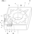
- the cutting tool 10 of the present embodiment includes a tool body 1 made of a sintered alloy, a hard coating 2 which is disposed on the outer surface of the tool body 1 and has a layer (a first layer 2a, which will be described later) formed of any of a carbide, a nitride, and a carbonitride, or a composite compound thereof, and a cutting edge 3 which is formed at the ridge portion of the tool body 1 and includes a portion of the hard coating 2 located at the ridge portion. That is, the cutting tool 10 of the present embodiment is a cutting insert in which the tool body 1 is coated with the hard coating 2. As shown in Fig. 1 , the cutting tool 10 includes a pair of plate surfaces 10a and 10b, an outer peripheral surface 10c, and a through-hole 10d.
- the pair of plate surfaces 10a and 10b have a polygonal shape and face the axial direction of the center axis C.
- the pair of plate surfaces 10a and 10b each have a quadrangular shape.
- the pair of plate surfaces 10a and 10b has one plate surface (front surface) 10a and the other plate surface (back surface) 10b.
- the one plate surface 10a and the other plate surface 10b are disposed apart from each other in the axial direction and face opposite to each other in the axial direction.
- the direction from the other plate surface 10b toward the one plate surface 10a is called one side in the axial direction
- the direction from the one plate surface 10a toward the other plate surface 10b is called the other side in the axial direction.
- a part (corner portion or the like) of the plate surface 10a faces a work material (not shown) during cutting.
- At least one plate surface 10a has a rake face 5.
- the rake face 5 forms at least a part of the plate surface 10a.
- the rake face 5 is disposed at least each of two corner portions of the four corner portions located on the peripheral edge portion of the plate surface 10a.
- the two corner portions are disposed at positions with 180-degree rotational symmetry about the center axis C.
- the rake face 5 has a land portion 5a and an inclined portion 5b.
- the land portion 5a is a portion of the rake face 5 connected to the cutting edge 3.
- the land portion 5a is disposed on the radially inward side of the cutting edge 3.
- the land portion 5a is an inclined surface that inclines toward the other side in the axial direction as it goes toward the radially inward side from the cutting edge 3.
- the land portion 5a may have a flat plate shape extending in a direction perpendicular to the center axis C.
- the inclined portion 5b is a portion of the rake face 5 located on the radially inward side of the land portion 5a.
- the inclined portion 5b is connected to the radially inner end portion of the land portion 5a.
- the inclined portion 5b is an inclined surface that inclines toward the other side in the axial direction as it goes toward the radially inward side from the land portion 5a.
- the amount of displacement in the axial direction of the inclined portion 5b per unit length along the radial direction is larger than the amount of displacement in the axial direction of the land portion 5a per unit length along the radial direction. That is, the inclination of the inclined portion 5b with respect to a virtual plane (not shown) perpendicular to the center axis C is larger than the inclination of the land portion 5a with respect to the virtual plane.
- the outer peripheral surface 10c is connected to the pair of plate surfaces 10a and 10b and faces the radially outward side. Both end portions of the outer peripheral surface 10c in the axial direction are connected to the pair of plate surfaces 10a and 10b. Specifically, the end portion of the outer peripheral surface 10c on one side in the axial direction is connected to the one plate surface 10a. The end portion of the outer peripheral surface 10c on the other side in the axial direction is connected to the other plate surface 10b.
- the outer peripheral surface 10c extends over the entire peripheral region of the cutting tool 10.
- the outer peripheral surface 10c has a flank face 6.
- the flank face 6 forms at least a part of the outer peripheral surface 10c.
- the flank face 6 is disposed in a portion of the outer peripheral surface 10c adjacent to each rake face 5.
- the through-hole 10d passes through the cutting tool 10 in the axial direction.
- the through-hole 10d opens to the pair of plate surfaces 10a and 10b and extends in the axial direction.
- the center axis of the through-hole 10d is disposed coaxially with the center axis C.
- the through-hole 10d has a circular hole shape.
- a clamp screw (not shown) or the like is inserted into the through-hole 10d.
- the cutting edge 3 is formed at a ridge portion where the rake face 5 and the flank face 6 are connected to each other, that is, an intersecting ridge portion between the rake face 5 and the flank face 6.
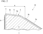
- the cutting edge 3 is disposed at least each of two corner portions of the four corner portions located on the peripheral edge portion of the plate surface 10a. As shown in Fig. 2 , in the present embodiment, the cutting edge 3 is subjected to round honing. The cutting edge 3 may also be subjected to chamfer honing.
- the cutting edge 3 has a corner edge portion 3a and a pair of straight edge portions 3b.
- the corner edge portion 3a has a convex curved shape that protrudes toward the radially outward side.
- the straight edge portions 3b have a straight line shape and are connected to the corner edge portion 3a.
- the pair of straight edge portions 3b are connected to both end portions of the corner edge portion 3a in an edge length direction.
- the edge length direction is the direction in which the cutting edge 3 extends, and specifically, the direction in which the edge portions 3a and 3b of the cutting edge 3 extend.
- the corner edge portion 3a and the pair of straight edge portions 3b are substantially V-shaped as a whole when viewed in the axial direction.
- the cutting edge 3 is formed of the ridge portion (the intersecting ridge portion) of the tool body 1 and a portion of the hard coating 2 coating the ridge portion.
- the tool body 1 has the same shape as the cutting tool 10 described above.
- the tool body 1 is made of a sintered alloy having a hard phase of at least one of a carbide or a nitride of Group 4a, 5a, and 6a metals of the periodic table and a mutual solid solution thereof, and Ni, Co, or a Ni-Co alloy.
- the tool body 1 is formed mainly of the hard phase and Ni, Co, or the Ni-Co alloy.
- the tool body 1 is made of a WC-based cemented carbide.
- the tool body 1 may be made of a TiC-based or Ti(C,N)-based cermet.
- the residual stress in a surface region of the tool body 1 is, for example, -1000 MPa or less, and preferably - 1500 MPa or less.
- the surface region (surface layer) of the tool body 1 may be a region from the surface of the tool body 1 to a depth of at least 1 ⁇ m.
- the hard coating 2 is formed on at least a part of the outer surface of the tool body 1 by a chemical vapor deposition method or a physical vapor deposition method.
- the hard coating 2 is disposed on the outer surface of the tool body 1 in a region including at least the cutting edge 3.
- the hard coating 2 is disposed on at least the cutting edge 3, the rake face 5, and the flank face 6.
- the hard coating 2 may be formed on the entire outer surface of the tool body 1.
- the film thickness of the hard coating 2 is, for example, 1 ⁇ m or more and 30 ⁇ m or less as a whole.
- the hard coating 2 is formed of a single layer or a plurality of layers.
- the hard coating 2 is formed of a plurality of layers laminated on the outer surface of the tool body 1.
- the hard coating 2 has the first layer 2a located on the outer surface of the tool body 1 and a second layer 2b located on the first layer 2a.
- the hard coating 2 may have a third layer (not shown) located on the second layer 2b.
- the hard coating 2 may be formed of four or more layers. Of the plurality of layers of the hard coating 2, the thickest layer is the first layer 2a.
- the hard coating 2 has the first layer 2a. That is, the hard coating 2 has at least the first layer (layer) 2a.
- the film thickness of the first layer 2a is, for example, 1 ⁇ m or more and 20 ⁇ m or less.
- the residual stress of the hard coating 2 specifically, the residual stress of the first layer 2a is 0 MPa or less (that is, the compressive residual stress is applied), and preferably -1000 MPa or less.
- the first layer 2a is disposed on the outer surface of the tool body 1 directly or indirectly with an intermediate layer (not shown) interposed therebetween.
- the first layer 2a is formed of any of a carbide, a nitride, and a carbonitride, or a composite compound thereof.
- the first layer 2a is, for example, a TiCN layer or the like. The TiCN layer subjected to the laser peening step described later improves the fracture resistance of the cutting edge 3.
- the second layer 2b is disposed on the outer surface of the first layer 2a directly or indirectly with an intermediate layer (not shown) interposed therebetween.
- the second layer 2b is formed of a carbide, a nitride, a carbonitride, an oxide, or a boride of Group 4a, 5a, and 6a metals of the periodic table, a carbide, a nitride, or a carbonitride of Si, an oxide or a nitride of Al, a mutual solid solution thereof, diamond, cubic boron nitride, or the like. Since the second layer 2b is not limited by the film type of the first layer 2a of the hard coating 2, those generally used as a hard coating for a cutting tool are listed here.
- the second layer 2b is, for example, an Al 2 O 3 layer or a TiN layer.
- the second layer 2b may be an Al 2 O 3 layer
- the third layer (not shown) may be a TiN layer.
- the second layer 2b is disposed at a portion other than the radially outer end portion of the inclined portion 5b, the land portion 5a, and the cutting edge 3.
- the second layer 2b may remain on the radially outer end portion of the inclined portion 5b, the land portion 5a, and the cutting edge 3 after the irradiation with the pulsed laser L.
- the method for manufacturing the cutting tool 10 of the present embodiment includes a sintering step, a film forming step, and the laser peening step.
- a green compact in the shape of the tool body 1, that is, an intermediate formed body formed by compacting in the manufacturing process of the tool body 1 is sintered.
- the green compact has a plate shape, specifically, a polygonal plate shape.
- the hard coating 2 having a layer formed of any of a carbide, a nitride, and a carbonitride, or a composite compound thereof is formed on the outer surface of the sintered tool body 1. That is, in the film forming step, the hard coating 2 having at least the first layer 2a is formed on the outer surface of the tool body 1.
- the first layer 2a is formed on the outer surface of the tool body 1 directly or indirectly with an intermediate layer (not shown) interposed therebetween
- the second layer 2b is formed on the first layer 2a directly or indirectly with an intermediate layer (not shown) interposed therebetween.
- the third layer may be formed on the second layer 2b directly or indirectly with an intermediate layer interposed therebetween.
- the hard coating 2 formed of four or more layers including the first layer 2a, the second layer 2b, and the third layer may be formed.
- the hard coating 2 is irradiated with a pulsed laser L having a pulse width of 100 ps (picosecond) or less.
- the hard coating 2 is irradiated with a pulsed laser L having a pulse width of 10 ps or less. More desirably, in the laser peening step, the hard coating 2 is irradiated with a pulsed laser L having a pulse width of 2 ps or less.
- the hard coating 2 is irradiated with a pulsed laser L having a pulse width of 10 fs (femtosecond) or more. More desirably, in the laser peening step, the hard coating 2 is irradiated with a pulsed laser L having a pulse width of 500 fs or more.
- the peak power density of the pulsed laser L is preferably 1 TW (terawatt)/cm 2 or more, more preferably 5 TW/cm 2 or more, and even more desirably 20 TW/cm 2 or more.
- the peak power density is 10 PW (petawatt)/cm 2 or less. The reason is that plasma due to air breakdown is generated from around 10 PW (petawatt)/cm 2 , and shields the laser beam.
- a range A covering the radially outer end portion of the inclined portion 5b, the land portion 5a, and the cutting edge 3 is irradiated with the pulsed laser L.
- the range A of at least 100 ⁇ m from the cutting edge 3 to the rake face 5 is irradiated with the pulsed laser L.
- the hard coating 2 is directly irradiated with the pulsed laser L instead of being indirectly irradiated with a nanosecond laser through a sacrificial film as in Patent Document 4 (Published Japanese Translation No. 2020-525301 of the PCT International Publication). That is, in the present embodiment, no sacrificial film is provided on the hard coating 2.
- laser irradiation as in the present embodiment is possible is that there is no feedback (stress release) due to heat because an ultrashort pulsed laser of 100 ps or less is used.
- the process is simple and the shock wave easily propagates, so that high compressive residual stress can be efficiently applied.
- the range A is hatched by laser beam scanning using a galvano scanner and an f ⁇ lens (not shown).
- the treatment atmosphere at this time is the air or a gas.
- the gas is, for example, an inert gas that suppresses oxidation.
- the laser beam is a pulsed laser L having a pulse width of 100 ps or less, and desirably, a laser beam adjusted by appropriately changing the pulse width and pulse energy so that the peak power density is 1 TW/cm 2 or more is used.
- the peak power density is a value calculated by pulse energy / (pulse width ⁇ spot area). It is appropriate that the spot diameter on the surface of the workpiece (the cutting tool 10) for the pulsed laser L is 10 ⁇ m or more and 200 ⁇ m or less.
- the spot diameter of the pulsed laser L irradiating the hard coating 2 is 10 ⁇ m or more and 200 ⁇ m or less.
- the spot diameter is 10 ⁇ m or more, local peeling of the hard coating 2 is less likely to occur during laser irradiation.
- the strength of the edge tip is significantly reduced. Therefore, it is necessary to suppress the occurrence of local peeling.
- the spot diameter is 200 ⁇ m or less, it is possible to suppress a decrease in the value of the compressive residual stress applied to the hard coating 2 and the surface of the tool body 1. It is more desirable that the spot diameter is set to 20 ⁇ m or more and 100 ⁇ m or less.
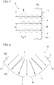
- a pulsed laser irradiation point interval Dy in the direction parallel to the cutting edge 3 and a pulsed laser irradiation point interval Dx in the direction orthogonal to the cutting edge 3 are different from each other. That is, the pulsed laser irradiation point interval Dy in the direction parallel to the cutting edge 3 may be smaller than the pulsed laser irradiation point interval Dx in the direction orthogonal to the cutting edge 3. Alternatively, the pulsed laser irradiation point interval Dx in the direction orthogonal to the cutting edge 3 may be smaller than the pulsed laser irradiation point interval Dy in the direction parallel to the cutting edge 3.
- the pulsed laser L is scanned in the direction orthogonal to the cutting edge 3.
- a scanning direction S of the pulsed laser L is a direction orthogonal to the straight edge portion 3b of the cutting edge 3.
- the scanning direction S of the pulsed laser L is a direction orthogonal to the corner edge portion 3a of the cutting edge 3.
- the scanning direction S is a direction that approaches the cutting edge 3 in the direction orthogonal to the cutting edge 3.
- the radially outer end portion of the inclined portion 5b, the land portion 5a, and the cutting edge 3 are scanned with the pulsed laser L in this order along the direction orthogonal to the cutting edge 3. That is, the pulsed laser L is scanned in a direction from the rake face 5 toward the cutting edge 3 in the direction orthogonal to the cutting edge 3.
- a plurality of circles shown by the two-dot chain lines in Fig. 3 represent spots B on the surface of the workpiece for the pulsed laser L. These spots B may not overlap each other as shown in the figure, or may overlap each other. In addition, as shown in Fig. 3 , the spots B are also located at the edge tip (end edge) of the cutting edge 3.
- the cutting tool 10 in which the hard coating 2 is formed on the outer surface of the tool body 1 is irradiated with a short pulsed laser having a pulse width of 100 ps or less, for example, in the air from above the hard coating 2.
- This treatment is so-called ultrashort pulsed laser peening, and is a technique of applying compressive residual stress to the surface of a workpiece by generating a shock wave in the workpiece by the mechanical reaction that occurs when a plasma generated by slightly processing the surface of the workpiece (cutting tool 10) subjected to laser irradiation is explosively diffused, and thus applying plastic deformation and crystal defects such as dislocations.
- the present embodiment by performing the laser peening under the above laser conditions, it is possible to stably apply compressive residual stress while suppressing the occurrence of vertical cracks in the hard coating 2 and the tool body 1.
- the pulse width to 100 ps or less, the effect of heat due to the laser irradiation is significantly suppressed, so that the peak power density, that is, the energy of the shock wave can be increased.
- a residual stress of 0 or less to the first layer 2a which is a layer contributing to the fracture resistance of the hard coating 2, and -1000 MPa or less to WC particles of the surface region of the tool body 1, that is, a compressive residual stress can be applied.
- a high compressive residual stress can be applied to both the hard coating 2 and the tool body 1 while suppressing the occurrence of vertical cracks by the laser peening step under the special laser conditions. Accordingly, the fracture resistance of the cutting edge 3 can be improved. Good cutting accuracy is maintained and the tool life is extended.
- the compressive residual stress can be stably applied, variation in the quality of the cutting tool 10 can be suppressed.
- the laser irradiation can be performed in the air and pre- and post-treatment steps are not particularly required, compared to a generally known stress control technique such as wet blasting, in the present embodiment, the treatment can be performed easily and at high speed, and the productivity is improved.
- the hard coating 2 is irradiated with a pulsed laser L having a pulse width of 10 ps or less.
- the hard coating 2 is irradiated with a pulsed laser L having a pulse width of 2 ps or less.
- a pulsed laser L having a pulse width of 2 ps or less.
- the hard coating 2 is irradiated with a pulsed laser L having a pulse width of 10 fs or more.
- the hard coating 2 is irradiated with a pulsed laser L having a pulse width of 500 fs or more. Accordingly, the above-mentioned effect becomes more remarkable.
- anisotropy is applied to the compressive residual stress of the hard coating 2 and the tool body 1 in the direction parallel to the cutting edge 3 and in the direction orthogonal to the cutting edge 3.
- the pulsed laser irradiation point interval Dy in the direction parallel to the cutting edge 3 and the pulsed laser irradiation point interval Dx in the direction orthogonal to the cutting edge 3 are caused to be different from each other.
- anisotropy can be applied to the compressive residual stress of the hard coating 2 and the tool body 1. That is, a difference of a predetermined value or more can be provided between the compressive residual stress value in the direction parallel to the cutting edge 3 and the compressive residual stress value in the direction orthogonal to the cutting edge 3.
- the compressive residual stress in the direction parallel to the cutting edge 3 can be higher than the compressive residual stress in the direction orthogonal to the cutting edge 3 (the absolute value of the residual stress can be increased). In this case, for example, it is possible to suppress the propagation of so-called thermal cracks in the direction orthogonal to the cutting edge 3.
- the compressive residual stress in the direction orthogonal to the cutting edge 3 can be higher than the compressive residual stress in the direction parallel to the cutting edge 3. In this case, for example, it is possible to suppress the propagation of so-called intermittent cracks in the direction parallel to the cutting edge 3.
- the spot diameter of the pulsed laser L irradiating the hard coating 2 is set to 10 ⁇ m or more and 200 ⁇ m or less.
- the spot diameter is 10 ⁇ m or more, local damage or peeling of the hard coating 2 is less likely to occur during laser irradiation.
- the spot diameter is 200 ⁇ m or less, it is possible to suppress a decrease in the value of the compressive residual stress applied to the hard coating 2 and the surface of the tool body 1.
- the pulsed laser L is scanned in the scanning direction S, that is, in the direction orthogonal to the cutting edge 3.
- the pulsed laser L is scanned in the direction parallel to the cutting edge 3, according to the above configuration of the present embodiment, damage to the hard coating 2 is suppressed.
- the pulsed laser L is scanned in a direction that approaches the cutting edge 3 from the position away from the cutting edge 3, that is, from the rake face 5 side toward the cutting edge 3 in the direction orthogonal to the cutting edge 3.
- the present invention is not limited to the above-described embodiment, and changes and the like in the configuration can be made without departing from the gist of the present invention, for example, as described below.
- anisotropy is applied to the compressive residual stress by causing the pulsed laser irradiation point interval Dy in the direction parallel to the cutting edge 3 and the pulsed laser irradiation point interval Dx in the direction orthogonal to the cutting edge 3 to be different from each other.
- anisotropy may be applied to the compressive residual stress by changing the peak power density in the direction orthogonal to the cutting edge 3, that is, in the scanning direction S of the pulsed laser L, or in the direction parallel to the cutting edge 3, that is, in a direction orthogonal to the scanning direction S of the pulsed laser L (for example, for each predetermined scanning unit) while setting the pulsed laser irradiation point intervals Dy and Dx to the same value (constant).
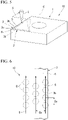
- Figs. 5 and 6 are diagrams describing a laser peening step of a modification example of the above-described embodiment.
- the pulsed laser L is scanned in a direction parallel to the cutting edge 3.
- the scanning direction S of the pulsed laser L is the direction parallel to the straight edge portion 3b and the corner edge portion 3a.
- anisotropy in the compressive residual stress can be applied by, for example, changing the ratio between the pulsed laser irradiation point intervals Dy and Dx.
- a nose portion (corner portion) of the cutting tool 10 is subjected to laser scanning in a curved shape along the corner edge portion 3a. At this time, the scanning speed becomes slow due to the curve.
- the laser peening treatment can be performed at high speed, and the production efficiency of the cutting tool 10 is high.
- the cutting tool 10 used for the edge tip replaceable insert holder is taken as an example, but the cutting tool 10 is not limited thereto.
- the cutting tool 10 may be used, for example, in an edge tip replaceable drill, an edge tip replaceable end mill, or the like for milling a work material.
- the cutting tool 10 which is a cutting insert is taken as an example, but the cutting tool 10 is not limited thereto.
- the cutting tool 10 may be, for example, a solid type drill, an end mill, a reamer, or other cutting tools.
- a plurality of laser-untreated cutting tools 10, that is, cutting inserts described in the above-described embodiment were prepared.
- these cutting tools 10 were cutting inserts having a JIS standard CNMG120408 shape.
- the tool body 1 was made of a WC cemented carbide having a composition of 7.5 mass% of Co and an average WC particle size of 1.5 ⁇ m.
- As the hard coating 2, 4 ⁇ m of a TiCN layer as the first layer 2a, 1 ⁇ m of an Al 2 O 3 layer as the second layer 2b, and 0.3 ⁇ m of a TiN layer as the third layer were formed on the outer surface of the tool body 1 in this order by a chemical vapor deposition (CVD) method.
- CVD chemical vapor deposition
- each cutting tool 10 was subjected to a laser treatment, that is, a laser peening step. Specifically, in the air, the rake face 5 of the cutting tool 10 was irradiated and scanned with a laser beam vertically, that is, in the axial direction such that the rake face 5 and the cutting edge 3 were subjected to the laser treatment. In all of the examples and comparative examples, no sacrificial film was formed on the hard coating 2, and the laser treatment was directly performed on the hard coating 2.
- the wavelength of the laser used was 1030 nm, the repetition rate was 10 kHz, the beam profile was Gaussian, and the spot diameter on the surface of the workpiece was ⁇ 30 ⁇ m.
- the laser peening step was performed on each of the cutting tools 10 under different laser conditions.
- the pulsed laser irradiation point intervals Dx and Dy were both set to 20 ⁇ m
- the pulse width was adjusted in a range of 10 fs (femtosecond) to 10 ns (nanosecond)
- the pulse energy was adjusted in a range of 0.4 mJ to 2 mJ
- the peak power density was changed in a range of 41 GW (gigawatt)/cm 2 to 5.66 PW (petawatt)/cm 2 .
- the cutting tools 10 irradiated with a pulsed laser having a pulse width of 100 ps or less (and a peak power density of 1 TW/cm 2 or more) were Examples 1 to 10 of the present invention, and the cutting tools subjected to laser irradiation under other laser conditions were Comparative Examples 1 to 4.
- the untreated cutting tool that was not subjected to laser irradiation was Comparative Example 5.
- the residual stress of each cutting tool 10 was measured as follows.
- the residual stresses of the tool body 1 and the hard coating 2 (first layer 2a) were measured by using an X-ray residual stress measuring device manufactured by Pulstec Industrial Co., Ltd. and using a cos ⁇ method.
- Using an X-ray shielding plate only a width of 0.3 mm was exposed from the tip end of the edge tip of the cutting edge 3, and measurement was performed so that the stress value was obtained only in the laser-treated portion.
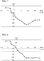
- Fig. 7 is a graph showing the relationship between the peak power density (horizontal axis) of the laser peening step and the residual stress value (vertical axis) applied to WC, that is, the tool body 1.
- Fig. 8 is a graph showing the relationship between the peak power density (horizontal axis) of the laser peening step and the residual stress value (vertical axis) applied to TiCN, that is, the first layer 2a of the hard coating 2.
- Examples 1 to 10 were determined as A, B, or C, so that the compressive residual stress was significantly increased. Specifically, it was confirmed that Examples 1 to 8 were determined as A or B, and a more significant effect was obtained. Particularly, it could be seen that Examples 4 to 6 were determined as A, and the compressive residual stress was particularly significantly increased.
- the residual stress of TiCN (hard coating) reached -2000 MPa, but the residual stress of WC (tool body) did not reach -2000 MPa. It is considered that the reason for this is that when the pulse width becomes smaller than a predetermined value, the time for which an impact is applied to the workpiece is shortened, and the impact does not sufficiently reach the deep part of the workpiece.
- Comparative Examples 1 to 4 were determined as D. Under the laser conditions of Comparative Examples 3 and 4 in which the pulse width was 1 ns or more, it was not possible to apply the compressive residual stress to WC (tool body). It is considered that the reason for this is the effect of heat.
- the laser peening step was performed on each of the cutting tools 10 under different laser conditions.
- the laser conditions all the pulsed laser irradiation point intervals Dy in the direction parallel to the cutting edge 3 were set to 15 ⁇ m, and the pulsed laser irradiation point intervals Dx in the direction orthogonal to the cutting edge 3 were changed to 25 ⁇ m, 35 ⁇ m, and 50 ⁇ m for each of the cutting tools 10 such that Examples 11 to 13 were set.
- the laser conditions other than the above were set to the same as those in Example 5 described above.
- the residual stress of each of the cutting tools 10 was measured in the same manner as in the measurement method described above. Then, the residual stress values ⁇ x and ⁇ y were measured by changing the X-ray incident direction in the x direction (the direction orthogonal to the cutting edge 3) and the y direction (the direction parallel to the cutting edge 3). The results are shown in Table 2 below.
- Example 13 As shown in Table 2, in each of Examples 11 to 13, there was a difference between the residual stress in the x direction and the residual stress in the y direction of TiCN (hard coating), and there was a difference between the residual stress in the x direction and the residual stress in the y direction of WC (tool body). That is, it was confirmed that in Examples 11 to 13, anisotropy was applied to the compressive residual stress. In addition, there was a trend that the anisotropy became more significant as the difference between the pulsed laser irradiation point intervals Dx and Dy increased. For example, in Example 13, a difference of more than 1000 MPa could be provided between the residual stress in the x direction and the residual stress in the y direction of the WC (tool body).
- a high compressive residual stress can be stably applied to a hard coating and a tool body, thereby improving the fracture resistance of a cutting edge. Therefore, industrial applicability is achieved.
Landscapes
- Engineering & Computer Science (AREA)
- Physics & Mathematics (AREA)
- Optics & Photonics (AREA)
- Mechanical Engineering (AREA)
- Plasma & Fusion (AREA)
- Chemical & Material Sciences (AREA)
- General Chemical & Material Sciences (AREA)
- Oil, Petroleum & Natural Gas (AREA)
- Chemical Kinetics & Catalysis (AREA)
- Thermal Sciences (AREA)
- Crystallography & Structural Chemistry (AREA)
- Materials Engineering (AREA)
- Metallurgy (AREA)
- Organic Chemistry (AREA)
- Laser Beam Processing (AREA)
- Cutting Tools, Boring Holders, And Turrets (AREA)
Applications Claiming Priority (3)
| Application Number | Priority Date | Filing Date | Title |
|---|---|---|---|
| JP2020017887 | 2020-02-05 | ||
| JP2021015304A JP6973672B2 (ja) | 2020-02-05 | 2021-02-02 | 切削工具の製造方法 |
| PCT/JP2021/004403 WO2021157716A1 (fr) | 2020-02-05 | 2021-02-05 | Procédé de fabrication d'un outil de coupe |
Publications (2)
| Publication Number | Publication Date |
|---|---|
| EP4082700A1 true EP4082700A1 (fr) | 2022-11-02 |
| EP4082700A4 EP4082700A4 (fr) | 2024-03-20 |
Family
ID=77200252
Family Applications (1)
| Application Number | Title | Priority Date | Filing Date |
|---|---|---|---|
| EP21750939.7A Pending EP4082700A4 (fr) | 2020-02-05 | 2021-02-05 | Procédé de fabrication d'un outil de coupe |
Country Status (4)
| Country | Link |
|---|---|
| US (1) | US20230105814A1 (fr) |
| EP (1) | EP4082700A4 (fr) |
| CN (1) | CN115052700B (fr) |
| WO (1) | WO2021157716A1 (fr) |
Families Citing this family (2)
| Publication number | Priority date | Publication date | Assignee | Title |
|---|---|---|---|---|
| TW202423586A (zh) * | 2022-10-27 | 2024-06-16 | 美商秀拉科技股份有限公司 | 雷射光束成形和圖案化的雷射製造系統及其方法 |
| CN118180429A (zh) * | 2024-04-12 | 2024-06-14 | 中国机械总院集团宁波智能机床研究院有限公司 | 刀具及刀具制备方法 |
Family Cites Families (19)
| Publication number | Priority date | Publication date | Assignee | Title |
|---|---|---|---|---|
| JPH06108258A (ja) | 1992-09-29 | 1994-04-19 | Toshiba Tungaloy Co Ltd | 高強度被覆焼結合金 |
| JP4087349B2 (ja) * | 2004-03-26 | 2008-05-21 | 株式会社東芝 | パルスレーザ表面処理方法 |
| JP4374306B2 (ja) * | 2004-10-08 | 2009-12-02 | 新日本製鐵株式会社 | 疲労特性に優れたコンロッドおよびその疲労特性向上方法 |
| JP4690895B2 (ja) * | 2005-01-11 | 2011-06-01 | 新日本製鐵株式会社 | 金属物体のレーザピーニング処理方法およびレーザピーニング処理方法で製造した金属物体 |
| JP4392405B2 (ja) * | 2005-04-19 | 2010-01-06 | 新日本製鐵株式会社 | コモンレールおよびその製造方法 |
| JP2007216327A (ja) * | 2006-02-15 | 2007-08-30 | Aisin Seiki Co Ltd | チップブレーカの形成方法 |
| JP5804354B2 (ja) | 2011-04-21 | 2015-11-04 | 住友電気工業株式会社 | 表面処理方法 |
| JP2013107143A (ja) * | 2011-11-17 | 2013-06-06 | Osg Corp | 工具および工具の製造方法 |
| RU2648719C2 (ru) * | 2012-12-21 | 2018-03-28 | Сандвик Интеллекчуал Проперти Аб | Режущий инструмент с покрытием и способ его изготовления |
| JP5729411B2 (ja) * | 2013-03-27 | 2015-06-03 | 住友電気工業株式会社 | 切削工具およびその製造方法 |
| JP6451982B2 (ja) * | 2014-12-08 | 2019-01-16 | 三菱マテリアル株式会社 | 表面被覆切削工具 |
| JP6604105B2 (ja) * | 2015-09-15 | 2019-11-13 | 日本製鉄株式会社 | 超硬工具及びその製造方法 |
| WO2018010961A1 (fr) | 2016-07-13 | 2018-01-18 | Asml Netherlands B.V. | Mesures d'erreur cyclique et procédures d'étalonnage dans des interféromètres |
| KR102232126B1 (ko) * | 2017-03-28 | 2021-03-24 | 스미또모 덴꼬오 하드메탈 가부시끼가이샤 | 절삭 공구의 제조 방법 |
| JP6521127B2 (ja) | 2017-04-21 | 2019-05-29 | 株式会社タンガロイ | 被覆切削工具 |
| NL2018981B1 (en) * | 2017-05-26 | 2018-12-07 | Univ Johannesburg Witwatersrand | Method and system for improving the surface fracture toughness of brittle materials, and a cutting tool produced by such method |
| JP6845328B2 (ja) * | 2017-07-27 | 2021-03-17 | 株式会社Subaru | レーザピーニング加工装置 |
| JP7620297B2 (ja) * | 2018-05-22 | 2025-01-23 | 国立大学法人 名古屋工業大学 | 構造部材及びその製造方法 |
| JP7096728B2 (ja) | 2018-07-26 | 2022-07-06 | シャープ株式会社 | 照明システム、照明システムの制御方法 |
-
2021
- 2021-02-05 WO PCT/JP2021/004403 patent/WO2021157716A1/fr not_active Ceased
- 2021-02-05 US US17/795,410 patent/US20230105814A1/en active Pending
- 2021-02-05 EP EP21750939.7A patent/EP4082700A4/fr active Pending
- 2021-02-05 CN CN202180012795.6A patent/CN115052700B/zh active Active
Also Published As
| Publication number | Publication date |
|---|---|
| WO2021157716A1 (fr) | 2021-08-12 |
| US20230105814A1 (en) | 2023-04-06 |
| CN115052700B (zh) | 2024-11-29 |
| CN115052700A (zh) | 2022-09-13 |
| EP4082700A4 (fr) | 2024-03-20 |
Similar Documents
| Publication | Publication Date | Title |
|---|---|---|
| EP2935647B1 (fr) | Outil de coupe revêtu et procédé pour sa fabrication | |
| EP2935653B1 (fr) | Outil de coupe revêtu et procédé de sa fabrication | |
| US20040234349A1 (en) | Throw-away tip | |
| CN108883469B (zh) | 硬质合金体的表面硬化 | |
| KR102905499B1 (ko) | 코팅된 절삭 공구의 처리 방법 | |
| EP4082700A1 (fr) | Procédé de fabrication d'un outil de coupe | |
| CN111558810A (zh) | 一种增减材和激光冲击强化复合的金属丝材增材制造工艺 | |
| JP6973672B2 (ja) | 切削工具の製造方法 | |
| WO2019065678A1 (fr) | Outil de coupe revêtu en surface ayant une excellente résistance à l'écaillage induit par l'adhérence | |
| Denkena et al. | Production of chip breakers on cemented carbide tools using laser ablation | |
| EP1477575B1 (fr) | Outil de coupe pour le travail du métal et procédé de fabrication des outils de coupe | |
| JP6191520B2 (ja) | 表面被覆切削工具 | |
| Marimuthu et al. | Picosecond laser machining of ceramic matrix composite | |
| WO2024203106A1 (fr) | Procédé de fabrication d'outil de coupe et outil de coupe | |
| JP2023095112A (ja) | 切削工具の製造方法 | |
| Nagarajan et al. | Femtosecond laser processing of cemented carbide for selective removal of cobalt | |
| JP7463772B2 (ja) | 切削工具 | |
| JP2023142141A (ja) | 切削工具及び切削工具の製造方法 | |
| JP6604105B2 (ja) | 超硬工具及びその製造方法 | |
| JP2022143008A (ja) | 切削工具および切削工具の製造方法 | |
| JP2024093295A (ja) | 切削工具 | |
| WO2023276934A1 (fr) | Procédé de fabrication d'un outil de coupe, et dispositif de traitement de martelage au laser | |
| Li et al. | Grit blast assisted laser milling/grooving of metallic alloys | |
| Jarosz | A review of the recent investigations regarding texturized cutting tools | |
| JP2022084322A (ja) | 切削工具および切削工具の製造方法 |
Legal Events
| Date | Code | Title | Description |
|---|---|---|---|
| STAA | Information on the status of an ep patent application or granted ep patent |
Free format text: STATUS: THE INTERNATIONAL PUBLICATION HAS BEEN MADE |
|
| PUAI | Public reference made under article 153(3) epc to a published international application that has entered the european phase |
Free format text: ORIGINAL CODE: 0009012 |
|
| STAA | Information on the status of an ep patent application or granted ep patent |
Free format text: STATUS: REQUEST FOR EXAMINATION WAS MADE |
|
| 17P | Request for examination filed |
Effective date: 20220728 |
|
| AK | Designated contracting states |
Kind code of ref document: A1 Designated state(s): AL AT BE BG CH CY CZ DE DK EE ES FI FR GB GR HR HU IE IS IT LI LT LU LV MC MK MT NL NO PL PT RO RS SE SI SK SM TR |
|
| DAV | Request for validation of the european patent (deleted) | ||
| DAX | Request for extension of the european patent (deleted) | ||
| REG | Reference to a national code |
Ref country code: DE Ref legal event code: R079 Free format text: PREVIOUS MAIN CLASS: B23B0027140000 Ipc: B23K0026000000 |
|
| A4 | Supplementary search report drawn up and despatched |
Effective date: 20240216 |
|
| RIC1 | Information provided on ipc code assigned before grant |
Ipc: B23K 103/16 20060101ALN20240212BHEP Ipc: B23K 101/20 20060101ALN20240212BHEP Ipc: B23B 27/14 20060101ALN20240212BHEP Ipc: C21D 10/00 20060101ALI20240212BHEP Ipc: B23K 26/356 20140101ALI20240212BHEP Ipc: B23K 26/0622 20140101ALI20240212BHEP Ipc: B23K 26/00 20140101AFI20240212BHEP |