EP4082909B1 - Buses de distribution d'air, aéronef comprenant des buses de distribution d'air et procédés d'utilisation des buses de distribution d'air - Google Patents
Buses de distribution d'air, aéronef comprenant des buses de distribution d'air et procédés d'utilisation des buses de distribution d'air Download PDFInfo
- Publication number
- EP4082909B1 EP4082909B1 EP22163359.7A EP22163359A EP4082909B1 EP 4082909 B1 EP4082909 B1 EP 4082909B1 EP 22163359 A EP22163359 A EP 22163359A EP 4082909 B1 EP4082909 B1 EP 4082909B1
- Authority
- EP
- European Patent Office
- Prior art keywords
- elongate
- outlet
- fluid flow
- inlet chamber
- chamber
- Prior art date
- Legal status (The legal status is an assumption and is not a legal conclusion. Google has not performed a legal analysis and makes no representation as to the accuracy of the status listed.)
- Active
Links
Images




Classifications
-
- B—PERFORMING OPERATIONS; TRANSPORTING
- B64—AIRCRAFT; AVIATION; COSMONAUTICS
- B64D—EQUIPMENT FOR FITTING IN OR TO AIRCRAFT; FLIGHT SUITS; PARACHUTES; ARRANGEMENT OR MOUNTING OF POWER PLANTS OR PROPULSION TRANSMISSIONS IN AIRCRAFT
- B64D13/00—Arrangements or adaptations of air-treatment apparatus for aircraft crew or passengers, or freight space
- B64D13/06—Arrangements or adaptations of air-treatment apparatus for aircraft crew or passengers, or freight space the air being conditioned
-
- B—PERFORMING OPERATIONS; TRANSPORTING
- B64—AIRCRAFT; AVIATION; COSMONAUTICS
- B64D—EQUIPMENT FOR FITTING IN OR TO AIRCRAFT; FLIGHT SUITS; PARACHUTES; ARRANGEMENT OR MOUNTING OF POWER PLANTS OR PROPULSION TRANSMISSIONS IN AIRCRAFT
- B64D13/00—Arrangements or adaptations of air-treatment apparatus for aircraft crew or passengers, or freight space
- B64D2013/003—Cabin ventilation nozzles
-
- B—PERFORMING OPERATIONS; TRANSPORTING
- B64—AIRCRAFT; AVIATION; COSMONAUTICS
- B64D—EQUIPMENT FOR FITTING IN OR TO AIRCRAFT; FLIGHT SUITS; PARACHUTES; ARRANGEMENT OR MOUNTING OF POWER PLANTS OR PROPULSION TRANSMISSIONS IN AIRCRAFT
- B64D13/00—Arrangements or adaptations of air-treatment apparatus for aircraft crew or passengers, or freight space
- B64D13/06—Arrangements or adaptations of air-treatment apparatus for aircraft crew or passengers, or freight space the air being conditioned
- B64D2013/0603—Environmental Control Systems
- B64D2013/0625—Environmental Control Systems comprising means for distribution effusion of conditioned air in the cabin
-
- B—PERFORMING OPERATIONS; TRANSPORTING
- B64—AIRCRAFT; AVIATION; COSMONAUTICS
- B64D—EQUIPMENT FOR FITTING IN OR TO AIRCRAFT; FLIGHT SUITS; PARACHUTES; ARRANGEMENT OR MOUNTING OF POWER PLANTS OR PROPULSION TRANSMISSIONS IN AIRCRAFT
- B64D13/00—Arrangements or adaptations of air-treatment apparatus for aircraft crew or passengers, or freight space
- B64D13/06—Arrangements or adaptations of air-treatment apparatus for aircraft crew or passengers, or freight space the air being conditioned
- B64D2013/0603—Environmental Control Systems
- B64D2013/0655—Environmental Control Systems with zone or personal climate controls
Definitions
- Distribution nozzles may control, direct, and/or regulate a flow of a fluid, such as air, and may be utilized in a variety of applications.
- air distribution nozzles may be utilized to form and/or define an air curtain, such as to permit and/or to facilitate different environmental controls on each side of the air curtain.
- air distribution nozzles may be utilized to regulate airflow within an aircraft.
- an air distribution nozzle may be utilized to form and/or to define an air curtain in a cockpit of the aircraft, such as to permit and/or facilitate independent environmental control of a pilot seating area and a co-pilot seating area of the aircraft.
- Conventional air distribution nozzles are relatively complex, utilize a significant number of separately manufactured and subsequently assembled parts, and/or are relatively expensive. Thus, there exists a need for improved air distribution nozzles, aswell as for aircraft that include improved air distribution nozzles and/or improved methodsof utilizing improved air distribution nozzles.
- an injector air outlet includes a temperature sensor and a smoke sensor to simultaneously carry out the functions of air recirculation and temperature and smoke monitoring within a closed interior space, such as a passenger cabin or a freight or cargo hold in an aircraft.
- the injector air outlet includes a housing wall with an injector mixing chamber therein.
- a primary supply air inlet receives primary supply air from the aircraft's air distribution duct network, and blows the primary supply air through an injection nozzle into the mixing chamber so as to create a reduced or negative pressure in the mixing chamber.
- Cabin exhaust air is sucked through asecondary air inlet and a secondary air channel into the mixing chamber, due to the reduced pressure or suction effect therein.
- WO2007/147259A1 in accordance with its abstract, states devices and systems are provided, that entrain ambient air within a primary stream of pressurised air, for use in a variety of applications including aircraft, buildings and other stationary structures.
- the ambient air isdrawn through an air treatment such a filter before entrainment within the primary stream.
- the combined streams are then delivered to a ventilation system, an air curtain or other suitable recipient of treated, thermally conditioned air.
- the systems include air curtain systems and ventilation systems for aircraft and other vehicles.
- CA3085629A1 in accordance with its abstract, states an overhead flow distribution assembly for an aircraft cabin, including a conduit defining a plenum having an inlet, upper outlets and lower outlets, the upper outlets spaced apart from each other along a longitudinal direction of the aircraft, the lower outlets spaced apart from each other along the longitudinal direction, the inlet being located between the upper outlets and the lower outlets, and a baffle extending within the plenum along the longitudinal direction, the baffle being located between the upper outlets and at least part of the inlet along a transverse direction normal to the longitudinal direction, the baffle having openings defined therethrough, the baffle configured to restrict airflow from the at least part of the inlet toward the upper outlets.
- a method of balancing a flow in an overhead flow distribution assembly for an aircraft cabin is also discussed.
- EP0292033A2 in accordance with its abstract, states a supply air ventilation system for providing symmetrical airflow distribution in the cabin of an aircraft, while avoiding excessive flow velocity.
- the ventilation system includes a supply duct from which pressurized supply air is delivered through a first nozzle at a relatively higher velocity and lower flow volume than through a second nozzle. Air flowing through the first nozzle attaches to a surface of an overhead storage bin that curves downwardly into the cabin of the aircraft due to the Coanda Effect, and mixes with the lower velocity higher volume air flowing through the second nozzle, thereby carrying it downwardly into the aircraft cabin.
- US3768394A in accordance with its abstract, states a fluid curtain generator according to the present invention comprising a generator for generating a high velocity stream of primary air and means for receiving the high velocity stream of air so as to mix the primary air with secondary air.
- the device also controls the rate of expansion of the thickness of the air curtain generated by mixing the primary and secondary air.
- the generator for generating the high velocity stream of primary air is preferably in the form of a conduit which is formed with a plurality of passageways opening outwardly therefrom. Mixing of primary and secondary air is achieved by passing the primary air through a venturi section and allowing it to expand in an expansion chamber while simultaneously inducing secondary air into the primary air stream.
- the primary air is directed between the venturi section formed at the inner end of a pair of guide plates arranged in a spaced relationship one on either side of the jet of primary air.
- the venturi section is spaced outwardly from the discharge of the primary air generator a distance sufficient to permit secondary air to be drawn in from the atmosphere on either side of the primary air stream.
- a closure plate may also be provided so that the atmosphere on one or other side of the venturi may be closed off to prevent secondary air being drawn into the venturi section from that side.
- an air distribution nozzle comprising an elongate inlet chamber extending along an elongate inlet chamber length measured along an elongate inlet chamber longitudinal axis of elongate inlet chamber, an elongate outlet chamber extending at least partially along the elongate inlet chamber length, and an elongate slot that extends between, and fluidly interconnects, the elongate inlet chamber and the elongate outlet chamber.
- the air distribution nozzle further comprises a motive fluid inlet port that extends into the elongate inlet chamber wherein the motive fluid inlet port is configured to receive a motive fluid flow along a motive flow axis, wherein the motive flow axis is parallel to the elongate inlet chamber longitudinal axis.
- the air distribution nozzle also comprises a suction inlet chamber that extends from a suction inlet port to the elongate inlet chamber.
- the suction inlet port opens into the suction inlet chamber and the suction inlet port is configured to receive a suction inlet fluid flow along a suction inlet flow axis.
- the air distribution nozzle also comprises a sensor port that extends into the suction inlet chamber.
- the air distribution nozzle further comprises an elongate outlet port that extends from the elongate outlet chamber.
- the elongate outlet port isconfigured to discharge an outlet fluid flow, which includes both the motive fluid flow and the suction inlet fluid flow, along an outlet flow axis.
- the outlet flow axis is oriented at an outlet flow skew angle relative to the motive flow axis.
- the air distribution nozzle may comprise a motive fluid acceleration structure, wherein the motive fluid acceleration structure isconfigured to accelerate the motive fluid flow to provide a target suction inlet flow rate for the suction inlet fluid flow.
- the motive fluid acceleration structure is positioned to accelerate the motive fluid flow prior to flow of the motive fluid flow past the separation structure.
- the air distribution nozzle may comprise a sensor, wherein the sensor includes, or is, a temperature sensor.
- the suction inlet flow axis is perpendicular, or at least substantially perpendicular, to: (i) the suction inlet port; and/or (ii) a transverse cross-section of the suction inlet port.
- the motive flow axis is: (i) perpendicular, or at least substantially perpendicular, to a transverse cross-section of the motive fluid inlet port; and/or (ii) parallel, or at least substantially parallel, to an elongate inlet chamber longitudinal axis of the elongate inlet chamber.
- the outlet flow axis is at least one of: (i) perpendicular, or at least substantially perpendicular, to a transverse cross-section of the elongate outlet port; (ii) perpendicular, or at least substantially perpendicular, to an outlet port longitudinal axis of the elongate outlet port; and (iii) perpendicular, or at least substantially perpendicular, to an outlet chamber longitudinal axis of the elongate outlet chamber.
- the motive fluid inlet port is oriented to direct the motive fluid flow along, or at least substantially along, an/the elongate inlet chamber longitudinal axisof the elongate inlet chamber.
- the transverse cross-section of the motive fluid inlet port is perpendicular, or at least substantially perpendicular, to a/the elongate inlet chamber longitudinal axis of the elongate inlet chamber.
- the elongate inlet chamber defines an/the elongate inlet chamber length and the elongate outlet chamber defines an outlet chamber length.
- the elongate inlet chamber is shaped to induce a pair of counter-rotating vortices in fluid flow from the elongate slot to the elongate outlet port.
- the outlet fluid flow is configured to generate an air curtain.
- the aircraft includes the air distribution nozzle and an air supply conduit configured to provide the motive fluid flow to the motive fluid inlet port.
- the air distribution nozzle is positioned within a cockpit of the aircraft, and further the outlet fluid flow is configured to generate an air curtain between a pilot seating area of the aircraft and a co-pilot seating area of the aircraft.
- the methods include providing the motive fluid flow to the elongate inlet chamber via the motive fluid inlet port and along a motive flow direction.
- the methods also include redirecting the motive fluid flow, within the elongate inlet chamber, to generate a slot fluid flow that flows through the elongate slot and into the elongate outlet chamber.
- the methods further include generating, within the elongate outlet chamber, a pair of counter-rotating vortices within the slot fluid flow.
- the methods also include discharging the outlet fluid flow from the elongate outlet port and along an outlet flow direction.
- the discharging includes discharging such that the outlet flow direction is oriented at the outlet flow skew angle relative to the motive flow direction.
- the discharging includes: (i) discharging a linear outlet fluid flow; and/or (ii) discharging a laminar outlet fluid flow.
- an air distribution nozzle may comprise using the air distribution nozzle to receive a motive fluid flow in a motive inlet direction, to redirect the motive fluid flow to an outlet flow direction that is oriented at an outlet flow skew angle relative to the motive flow direction, and to generate an outlet fluid flow that defines an air curtain.
- an air distribution nozzle is used to both detect a temperature of air within an interior of an aircraft and provide an outlet fluid flow to the interior of the aircraft.
- Figs. 1-10 provide illustrative, non-exclusive examples of air distribution nozzles 100, of aircraft 10, and/or of methods according to the present disclosure. Elementsthat serve a similar, or at least substantially similar, purpose are labeled with like numbers in each of Figs. 1-10 , and these elements may not be discussed in detail herein with reference to each of Figs. 1-10 . Similarly, all elements may not be labeled in each of Figs. 1-10 , but reference numerals associated therewith may be utilized herein for consistency. Elements, components, and/or features that are discussed herein with reference to one or more of Figs. 1-10 may be included in and/or utilized with any of Figs. 1-10 without departing from the scope of the present disclosure.
- elements that are likely to be included in agiven (i.e., a particular) example are illustrated in solid lines, while elements that are optional to a given example are illustrated in dashed lines.
- elements that are shown in solid lines are not essential to all examples, and an element shown in solid lines may be omitted from a particular example.
- Fig. 1 is a schematic illustration of examples of an aircraft 10 that may include and/or utilize an air distribution nozzle 100, according to the present disclosure.
- Aircraft 10 also may include an air supply conduit 30, which may be configured to provide a motive fluid flow 70 to air distribution nozzle 100.
- Air distribution nozzles 100 may be configured to control, to direct, and/or to regulate fluid, or air, flow within, or within an interior 11 of, aircraft 10 in any suitable manner. Examples of air distribution nozzles 100 are disclosed herein.
- air distribution nozzles 100 may be positioned within a cockpit 20 of aircraft 10. In some such examples, air distribution nozzles 100 may be configured to generate an outlet fluid flow 90 that may function as an air curtain 98. In some such examples, air curtain 98 may flow between a pilot seating area 12 and a co-pilot seating area 14 of aircraft 10, such as to permit, facilitate, and/or enable independent environmental control between the pilot seating area and the co-pilot seating area.
- air curtain 98 may decrease a potential for cross-contamination between pilot seating area 12 and co-pilot seating area 14. Stated another way, air curtain 98 may entrain airborne contaminants, such as particulate material, bacteria, and/or viruses, thereby decreasing flow of the airborne contaminants between pilot seating area 12 and co-pilot seating area 14.
- Air distribution nozzle 100 may include a sensor 282, which may be configured to detect one or more properties of air proximate and/or within air distribution nozzle 100.
- aircraft 10 further may include an environmental control system 40, which may be in communication with sensor 282.
- environmental control system 40 may be configured to control a flow rate of motive fluid flow 70 based, at least in part, on a sensor reading from sensor 282.
- FIG. 2 is a schematic illustration of examples of an air distribution nozzle 100 according to the present disclosure.
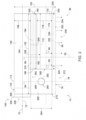
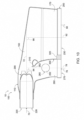
- Fig. 3 is a less schematic side view illustrating an example of an air distribution nozzle 100 according to the present disclosure
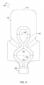
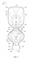
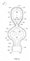
- Figs. 4-9 provide additional views of air distribution nozzle 100 of Fig. 3 .
- Fig. 4 is a bottom view of the air distribution nozzle of Fig. 3
- Fig. 5 is a left end view of the air distribution nozzle of Fig. 3
- Fig. 6 is a right end view of the air distribution nozzle of Fig. 3
- Fig. 7 is a cross-sectional view of the air distribution nozzle of Fig. 3 taken along line 7-7 of Fig. 3
- FIG. 8 is a cross-sectional view of the air distribution nozzle of Fig. 3 taken along line 8-8 of Fig. 3
- Fig. 9 is a cross-sectional view of the air distribution nozzle of Fig. 3 taken along line 9-9 of Fig. 5
- Fig. 10 is a cross-sectional view of the air distribution nozzle of Fig. 3 taken along line 10-10 of Fig. 5 .
- Air distribution nozzles 100 of Figs. 2-10 may include and/or be more detailed illustrations of air distribution nozzles 100 of Fig. 1 .
- any of the structures, functions, and/or features of air distribution nozzles 100 of Figs. 2-10 may be included in and/or utilized with aircraft 10 of Fig. 1 and/or air distribution nozzles 100 thereof without departing from the scope of the present disclosure.
- any of the structures, functions, and/or features of aircraft 10 of Fig. 1 may be utilized with air distribution nozzles 100 of Figs. 2-10 .
- air distribution nozzles 100 include an elongate inlet chamber 150 and an elongate outlet chamber 170.
- Elongate inlet chamber 150 extends along an elongate inlet chamber length 152, as illustrated in Fig. 2
- elongate outlet chamber 170 extends, or also extends, at least partially along the elongate inlet chamber length.
- Air distribution nozzles 100 also include an elongate slot 190, which also may be referred to herein and/or may be a tapered elongate slot 190.
- Elongate slot 190 extends between, and fluidly interconnects, elongate inlet chamber 150 and elongate outlet chamber 170.
- Air distribution nozzles 100 further include a motive fluid inlet port 220, which extends into elongate inlet chamber 150, and an elongate outlet port 230, which extends from elongate outlet chamber 170.
- Motive fluid inlet port 220 is configured to receive motive fluid flow 70 along a motive flow axis 72 and/or in a motive flow direction (as indicated by the arrow on motive fluid flow 70).
- Air distribution nozzles 100 also include a suction inlet chamber 260.
- Suction inlet chamber 260 extends from a suction inlet port 270 to elongate inlet chamber 150.
- Suction inlet port 270 opens into suction inlet chamber 260 and is configured to receive a suction inlet fluid flow 76 along a suction inlet flow axis 78. Additionally or alternatively, suction inlet port 270 may be configured to receive suction inlet fluid flow 76 in and/or along a suction inlet flow direction (as indicated by the arrow on suction inlet fluid flow 76), which may be oriented at a suction flow skew angle 94 relative to motive flow axis 72.
- Elongate outlet port 230 is configured to discharge outlet fluid flow 90 along an outlet flow axis 92 and/or in an outlet flow direction (as indicated by the arrow on outlet fluid flow 90).
- Outlet flow axis 92 is oriented at an outlet flow skew angle 96 relative to motive flow axis 72. Stated another way, the motive flow direction may be referred to herein as being at outlet flow skew angle 96 relative to the outlet flow direction.
- Outlet fluid flow 90 includes both motive fluid flow 70 and suction inlet fluid flow 76.
- motive fluid flow 70 may be provided to elongate inlet chamber 150 via motive fluid inlet port 220, in the motive flow direction, and/or along motive flow axis 72. This may include providing motive fluid flow 70 via air supply conduit 30 of Fig. 1 .
- Motive fluid flow 70 may be redirected, within elongate inlet chamber 150 to generate a slot fluid flow 206 that flows through elongate slot 190 and/or into elongate outlet chamber 170.
- a pair of counter-rotating vortices 80 may be generated from and/or within slot fluid flow 206.
- Outlet fluid flow 90 which may be generated from counter-rotating vortices 80, then may be discharged from elongate outlet port 230 along outlet flow axis 92 and/or in the outlet flow direction.
- air distribution nozzles 100 may be referred to herein as being configured to redirect motive fluid flow 70 from the motive flow direction to the outlet flow direction and also to redirect suction inlet fluid flow 76 from the suction inlet flow direction to the outlet flow direction, such as to produce and/or generate outlet fluid flow 90.
- This redirection may be such that outlet fluid flow 90 is uniform, or at least substantially uniform, along an outlet port length 232 of elongate outlet port 230, such that the outlet fluid flow is laminar, and/or such that the outlet fluid flow is at least substantially uniformly directed in the outlet flow direction. Additionally or alternatively, this redirection may be such that the outlet flow direction is oriented at the outlet flow skew angle relative to the motive flow direction.
- suction inlet port 270, suction inlet chamber 260, and/or sensor port 280 within air distribution nozzles 100, may provide several benefits over conventional air distribution nozzles that do not include suction inlet port 270, suction inlet chamber 260, and/or sensor port 280.
- sensor 282 which may be positioned within sensor port 280, may be configured to measure one or more properties of suction inlet fluid flow 76, such as a temperature, a pressure, and/or a moisture content of the suction inlet fluid flow.
- Suction flow skew angle 94 and/or outlet flow skew angle 96 which collectively may be referred to herein as angles 94/96 may include and/or be any suitable angle between motive flow axis 72 and suction inlet flow axis 78 and/or outlet flow axis 92, respectively.
- suction inlet flow axis 78 and outlet flow axis 92 may be parallel to one another. Additionally or alternatively, suction flow skew angle 94 may be within a threshold angle difference of outlet flow skew angle 96. Examples of the threshold angle difference include angle differences of at least 1 degree, at least 2.5 degrees, at least 5 degrees, at least 10 degrees, at least 15 degrees, at most 30 degrees, at most 25 degrees, at most 20 degrees, at most 15 degrees, at most 10 degrees, and/or at most 5 degrees.
- air distribution nozzles 100 and/or motive fluid inlet ports 220 thereof may include and/or may be associated with a motive fluid acceleration structure 290.
- Motive fluid acceleration structure 290 when present, may be adapted, configured, sized, and/or shaped to accelerate, or increase a velocity of, motive fluid flow 70 as the motive fluid flow exits motive fluid inlet port 220 and/or enters elongate inlet chamber 150.
- Examples of motive fluid acceleration structure 290 include a region of reduced cross-sectional area, an at least partially tapered region, a venturi, an orifice, and/or a plurality of orifices.
- Elongate slot 190 may have and/or define any suitable shape, configuration, and/or conformation that tapers along slot length 192 thereof, that extends between elongate inlet chamber 150 and elongate outlet chamber 170, and/or that fluidly interconnects elongate inlet chamber 150 and elongate outlet chamber 170.
- elongate slot 190 may extend, or may continuously extend, between a first slot end 196 and a second slot end 200.
- elongate slot 190 may include a plurality of slot segments 204. In such a configuration, each slot segment of the plurality of slot segments may fluidly interconnect a given region of elongate inlet chamber 150 with a corresponding region of elongate outlet chamber 170.
- first slot end 196 may be relatively proximate to motive fluid inlet port 220 and/or second slot end 200 may be relatively distal from motive fluid inlet port 220.
- first slot width 198 may be greater than second slot width 202.
- elongate slot 190 may taper, taper monotonically, taper linearly, and/or arcuately taper from first slot width 198 to second slot width 202 and/or between first slot width 198 and second slot width 202.
- first slot width 198 may differ from second slot width 202 by any suitable amount and/or proportion.
- a ratio of first slot width 198 to second slot width 202 may be at least 1.1, at least 1.2, at least 1.3, at least 1.4, at least 1.5, at least 1.6, at least 1.7, at least 1.8, at least 1.9, at least 2.0, at most 4.0, at most 3.8, at most 3.6, at most 3.4, at most 3.2, at most 3.0, at most 2.9, at most 2.8, at most 2.7, at most 2.6, at most 2.5, at most 2.4, at most 2.3, at most 2.2, at most 2.1, at most 2.0, at most 1.9, at most 1.8, at most 1.7, at most 1.6, and/or at most 1.5.
- first slot width 198 examples include widths of at least 1.5 millimeters (mm), at least 1.6 mm, at least 1.7 mm, at least 1.8 mm, at least 1.9 mm, at least 2 mm, at least 2.1 mm, at least 2.2 mm, at least 2.3 mm, at least 2.4 mm, at most 3 mm, at most 2.9 mm, at most 2.8 mm, at most 2.7 mm, at most 2.6 mm, at most 2.5 mm, at most 2.4 mm, at most 2.3 mm, at most 2.2 mm, at most 2.1 mm, and/or at most 2 mm.
- mm millimeters
- Examples of second slot width 202 include widths of at least 0.5 mm, at least 0.6 mm, at least 0.7 mm, at least 0.8 mm, at least 0.9 mm, at least 1 mm, at least 1.1 mm, at least 1.2 mm, at least 1.3 mm, at least 1.4 mm, at most 2 mm, at most 1.9 mm, at most 1.8 mm, at most 1.7 mm, at most 1.6 mm, at most 1.5 mm, at most 1.4 mm, at most 1.3 mm, at most 1.2 mm, at most 1.1 mm, and/or at most 1 mm.
- elongate inlet chamber width 160 which also may be referred to herein as a width 160 of elongate inlet chamber 150, may decrease, or monotonically decrease, along motive flow axis 72 and/or in the motive flow direction.
- a maximum value of elongate inlet chamber width 160 which also may be referred to herein as a maximum width of elongate inlet chamber 150, may be at least a threshold elongate inlet chamber width multiple of a minimum value of elongate inlet chamber width 160, which also may be referred to herein as a minimum width of the elongate inlet chamber.
- elongate exit structure 250 may define a diffuser mounting structure 252.
- Diffuser mounting structure 252 when present, may be adapted, configured, shaped, and/or sized to receive an air diffuser 254 and/or to operatively attach the air diffuser to a remainder of air distribution nozzles 100.
- air distribution nozzles 100 further include air diffuser 254, which may be operatively attached to diffuser mounting structure 252.
- Examples of diffuser mounting structure 252 include a region that is shaped to receive air diffuser 254 and/or any suitable fastener.
- Examplesof air diffuser 254 include a screen, a grill, and/or a louvre.
- air distribution nozzles 100 may include and/or may be defined by a nozzle body 110.
- Nozzle body 110 when present, may define elongate inlet chamber 150, elongate outlet chamber 170, elongate slot 190, motive fluid inlet port 220, elongate exit structure 250, suction inlet chamber 260, suction inlet port 270, sensor port 280, and/or motive fluid acceleration structure 290.
- nozzle body 110 may include and/or be a monolithic, or a unitary, nozzle body 110, such that the nozzle body 110 may be formed and/or defined by an additive manufacturing process. In some examples, and as illustrated in Fig.
- separation structure 300 may include an outlet fluid flow redirection structure 320, as illustrated in Figs. 2 and 10 .
- Outlet fluid flow redirection structure 320 may be positioned within elongate outlet port 230 and/or may at least partially define elongate outlet port 230.
- Outlet fluid flow redirection structure 320 may be shaped, sized, and/or positioned to direct outlet fluid flow 90 away, or at least partially away, from suction inlet fluid flow 76 and/or from suction inlet port 270.
- air distribution nozzles 100 may not include, or may be free from, baffles, flow straighteners, and/or flow guides that may extend and/or project within and/or between elongate inlet chamber 150, elongate outlet chamber 170, elongate slot 190, motive fluid inlet port 220, and/or elongate outlet port 230.
- an object that is at least substantially formed from a material includes objects for which at least 75%of the objects are formed from the material and also includes objects that are completely formed from the material.
- a first length that is at least substantially as long as a second length includes first lengths that are within 75% of the second length and also includes first lengthsthat are as long as the second length.
Landscapes
- Health & Medical Sciences (AREA)
- General Health & Medical Sciences (AREA)
- Pulmonology (AREA)
- Engineering & Computer Science (AREA)
- Aviation & Aerospace Engineering (AREA)
- Jet Pumps And Other Pumps (AREA)
Claims (15)
- Buse de distribution d'air (100), comprenant :une chambre d'entrée allongée (150) s'étendant le long d'une longueur de chambre d'entrée allongée (152) mesurée le long d'un axe longitudinal de chambre d'entrée allongée (154) de la chambre d'entrée allongée (150) ;une chambre de sortie allongée (170) s'étendant au moins partiellement le long de la longueur de chambre d'entrée allongée (152) ;une fente allongée (190) qui s'étend entre, et interconnecte de manière fluidique, la chambre d'entrée allongée (150) et la chambre de sortie allongée (170) ;un orifice d'entrée de fluide moteur (220) qui s'étend dans la chambre d'entrée allongée (150), dans laquelle l'orifice d'entrée de fluide moteur (220) est configuré pour recevoir un écoulement de fluide moteur (70) le long d'un axe d'écoulement moteur (72), dans laquelle l'axe d'écoulement moteur (72) est parallèle à l'axe longitudinal de chambre d'entrée allongée (154) ;une chambre d'entrée d'aspiration (260) qui s'étend d'un orifice d'entrée d'aspiration (270) à la chambre d'entrée allongée (150), dans laquelle l'orifice d'entrée d'aspiration (270) s'ouvre dans la chambre d'entrée d'aspiration (260), dans lequel l'orifice d'entrée d'aspiration (270) est configuré pour recevoir un écoulement de fluide d'entrée d'aspiration (76) le long d'un axe d'écoulement d'entrée d'aspiration (78) ;un orifice de capteur (280) qui s'étend dans la chambre d'entrée d'aspiration (260) ; etun orifice de sortie allongé (230) qui s'étend à partir de la chambre de sortie allongée (170), dans laquelle l'orifice de sortie allongé (230) est configuré pour décharger un écoulement de fluide de sortie (90), qui comprend à la fois l'écoulement de fluide moteur (70) et l'écoulement de fluide d'entrée d'aspiration (76), le long d'un axe d'écoulement de sortie (92), et dans laquelle en outre l'axe d'écoulement de sortie (92) est orienté selon un angle d'inclinaison d'écoulement de sortie (96) par rapport à l'axe d'écoulement moteur (72).
- Buse de distribution d'air (100) selon la revendication 1, comprenant en outre une structure d'accélération de fluide moteur (290) configurée pour augmenter une vitesse de l'écoulement de fluide moteur (70) lorsque l'écoulement de fluide moteur (70) entre dans la chambre d'entrée allongée (150).
- Buse de distribution d'air (100) selon la revendication 2, dans laquelle la structure d'accélération de fluide moteur (290) inclut au moins un parmi :(i) une région d'aire de section transversale réduite ;(ii) une région effilée ou au moins partiellement effilée ;(iii) une ouverture (292) ; et(iv) une pluralité d'ouvertures (292).
- Buse de distribution d'air (100) selon l'une quelconque des revendications 1 à 3, comprenant en outre une structure de séparation (300) qui s'étend entre, et isole de manière fluidique, la chambre de sortie allongée (170) et la chambre d'entrée d'aspiration (260).
- Buse de distribution d'air (100) selon la revendication 4, dans laquelle la structure de séparation (300) définit, ou définit au moins partiellement, au moins l'une de la chambre de sortie allongée (170) et de la chambre d'entrée d'aspiration (260).
- Buse de distribution d'air (100) selon la revendication 4 ou 5, dans laquelle :la structure de séparation (300) comprend une surface mise en forme de manière aérodynamique (310) qui définit, ou partiellement au moins définit, une région (262) de la chambre d'entrée d'aspiration (260) qui s'ouvre dans la chambre d'entrée allongée (150) ; et, facultativement,la région (262) de la chambre d'entrée d'aspiration (260) qui s'ouvre dans la chambre d'entrée allongée (150) comprend une surface convexe et/ou une surface à effet Coanda.
- Buse de distribution d'air (100) selon l'une quelconque des revendications 4 à 6, dans laquelle la structure de séparation (300) comprend en outre une structure de redirection d'écoulement de fluide de sortie (320) mise en forme pour diriger l'écoulement de fluide de sortie (90) à l'écart de l'écoulement de fluide d'entrée d'aspiration (76).
- Buse de distribution d'air (100) selon la revendication 7, dans laquelle la structure de redirection d'écoulement de fluide de sortie (320) est positionnée à l'intérieur de l'orifice de sortie allongé (230) et/ou définit, ou définit au moins partiellement, l'orifice de sortie allongé (230).
- Buse de distribution d'air (100) selon l'une quelconque des revendications 1 à 8, dans laquelle la buse de distribution d'air (100) comprend en outre un capteur (282) positionné à l'intérieur de l'orifice de capteur (280).
- Buse de distribution d'air (100) selon l'une quelconque des revendications 1 à 9, dans laquelle la chambre d'entrée d'aspiration (260) est mise en forme pour diriger l'écoulement de fluide d'entrée d'aspiration (76) dans la chambre d'entrée allongée (150) de sorte que l'écoulement de fluide d'entrée d'aspiration (76) se combine avec l'écoulement de fluide moteur (70) à l'intérieur de la chambre d'entrée allongée (150).
- Buse de distribution d'air (100) selon l'une quelconque des revendications 1 à 10, dans laquelle :l'orifice d'entrée d'aspiration (270) est situé sur le même plan que l'orifice de sortie allongé (230) ; et, facultativement,l'axe d'écoulement d'entrée d'aspiration (78) est parallèle à l'axe d'écoulement de sortie (92).
- Aéronef (10), comprenant :la buse de distribution d'air (100) selon l'une quelconque des revendications 1 à 11 ; etun conduit d'alimentation en air (30) configuré pour fournir l'écoulement de fluide moteur (70) à l'orifice d'entrée de fluide moteur (220) ; et, facultativement, dans lequel :
l'aéronef (10) comprend en outre un système de commande d'environnement (40) en communication avec le capteur (282), et le système de commande d'environnement (40) est configuré pour commander un débit d'écoulement de l'écoulement de fluide moteur (70) sur la base, au moins en partie, d'une lecture de capteur à partir du capteur (282). - Procédé d'utilisation de la buse de distribution d'air (100) selon l'une quelconque des revendications 1 à 12, le procédé comprenant les étapes consistant à :fournir l'écoulement de fluide moteur (70) à la chambre d'entrée allongée (150) via l'orifice d'entrée de fluide moteur (220) et le long d'une direction d'écoulement moteur ;rediriger, à l'intérieur de la chambre d'entrée allongée (150), l'écoulement de fluide moteur (70) pour générer un écoulement de fluide de fente (206) qui s'écoule à travers la fente allongée (190) et jusque dans la chambre de sortie allongée (170), en générant ainsi, à l'intérieur de la chambre de sortie allongée (170), une paire de tourbillons contrarotatifs (80) à l'intérieur de l'écoulement de fluide de fente (206) ; etdécharger, à partir de l'orifice de sortie allongé (230), l'écoulement de fluide de sortie (90) le long d'une direction d'écoulement de sortie.
- Procédé selon la revendication 13, dans lequel, en réponse à la fourniture de l'écoulement de fluide moteur (70), le procédé comprend en outre une génération d'une aspiration qui attire l'écoulement de fluide d'entrée d'aspiration (76) jusque dans la chambre d'entrée d'aspiration (260) via l'orifice d'entrée d'aspiration (270).
- Procédé selon la revendication 14, dans lequel le procédé comprend en outre les étapes consistant à :mélanger l'écoulement de fluide moteur (70) avec l'écoulement de fluide d'entrée d'aspiration (76) à l'intérieur de la chambre d'entrée allongée (150) ; et/oumesurer une température de l'écoulement de fluide d'entrée d'aspiration (76) et, facultativement, réguler sélectivement un débit d'écoulement de l'écoulement de fluide moteur (70) sur la base, au moins en partie, de la température de l'écoulement de fluide d'entrée d'aspiration (76).
Applications Claiming Priority (2)
| Application Number | Priority Date | Filing Date | Title |
|---|---|---|---|
| US202163181084P | 2021-04-28 | 2021-04-28 | |
| US17/361,116 US11958616B2 (en) | 2020-09-09 | 2021-06-28 | Air distribution nozzles, aircraft that include air distribution nozzles, and methods of utilizing air distribution nozzles |
Publications (2)
| Publication Number | Publication Date |
|---|---|
| EP4082909A1 EP4082909A1 (fr) | 2022-11-02 |
| EP4082909B1 true EP4082909B1 (fr) | 2024-07-03 |
Family
ID=80928966
Family Applications (1)
| Application Number | Title | Priority Date | Filing Date |
|---|---|---|---|
| EP22163359.7A Active EP4082909B1 (fr) | 2021-04-28 | 2022-03-21 | Buses de distribution d'air, aéronef comprenant des buses de distribution d'air et procédés d'utilisation des buses de distribution d'air |
Country Status (1)
| Country | Link |
|---|---|
| EP (1) | EP4082909B1 (fr) |
Family Cites Families (6)
| Publication number | Priority date | Publication date | Assignee | Title |
|---|---|---|---|---|
| US3768394A (en) * | 1971-06-18 | 1973-10-30 | Powlesland Eng Ltd | Device for producing dynamic flow in fluids to form curtains of the fluid |
| US4819548A (en) * | 1987-05-07 | 1989-04-11 | The Boeing Company | Dual nozzle cabin ventilation system |
| JPH09122428A (ja) * | 1995-11-02 | 1997-05-13 | Daikin Ind Ltd | 空気清浄機 |
| DE19728595C1 (de) * | 1997-07-04 | 1998-09-17 | Daimler Benz Aerospace Airbus | Injektorluftauslaß zur Temperatur- und Rauchgasüberwachung |
| CA2655553C (fr) * | 2006-06-23 | 2013-04-02 | Veft Aerospace Technology Inc. | Controle de courant d'air d'entrainement et dispositifs de filtration |
| EP3728036B1 (fr) * | 2017-12-18 | 2023-07-19 | MHI RJ Aviation ULC | Ensemble de distribution de circulation de plafond pour cabine d'aéronef |
-
2022
- 2022-03-21 EP EP22163359.7A patent/EP4082909B1/fr active Active
Also Published As
| Publication number | Publication date |
|---|---|
| EP4082909A1 (fr) | 2022-11-02 |
Similar Documents
| Publication | Publication Date | Title |
|---|---|---|
| US4819548A (en) | Dual nozzle cabin ventilation system | |
| US6024639A (en) | Injector air outlet with a sensor for temperature and smoke monitoring | |
| US8206475B2 (en) | Entrainment air flow control and filtration devices | |
| US20230202263A1 (en) | Passenger cabin air distribution system and method of using | |
| US4742760A (en) | Aircraft cabin ventilation system | |
| US11999490B2 (en) | Air curtain systems and methods for vehicle cabins | |
| CN106240287B (zh) | 用于车辆的个人空气流动装置 | |
| CN101378957B (zh) | 具有旋风排气装置的飞行器空调系统 | |
| CA2351294C (fr) | Orifices de ventilation de cabine d'avion montes au plafond | |
| EP3967603B1 (fr) | Buses de distribution d'air, aéronef comprenant des buses de distribution d'air et procédés d'utilisation des buses de distribution d'air | |
| CN214396748U (zh) | 具有空调系统的交通工具 | |
| CA2890773A1 (fr) | Mecanismes de diffuseur d'air, methodes et appareils | |
| US11142264B2 (en) | Draft turbulence reduction system and method | |
| US9011216B1 (en) | Diversion directional nozzle | |
| EP4082909B1 (fr) | Buses de distribution d'air, aéronef comprenant des buses de distribution d'air et procédés d'utilisation des buses de distribution d'air | |
| CN210792743U (zh) | 车辆的空调出风口结构和车辆 | |
| US9505498B2 (en) | Aircraft cabin airflow nozzles and associated systems and methods | |
| JP2016011858A (ja) | 風洞実験装置 | |
| US3895567A (en) | Air outlet arrangement for air conditioning and ventilating apparatus | |
| US20100317277A1 (en) | Air outlet | |
| US11548647B2 (en) | Air-conditioning duct structure of aircraft, aircraft, and method of manufacturing aircraft | |
| RU2052732C1 (ru) | Устройство для распределения воздуха | |
| KR20140124449A (ko) | 항공기 좌석용 공기막 형성장치 | |
| EP3294627B1 (fr) | Dispositif d'aération pour une soufflerie verticale | |
| US20250262915A1 (en) | System for Supplying an Air Flow to an Air Diffuser and Air Diffuser System for a Vehicle |
Legal Events
| Date | Code | Title | Description |
|---|---|---|---|
| PUAI | Public reference made under article 153(3) epc to a published international application that has entered the european phase |
Free format text: ORIGINAL CODE: 0009012 |
|
| STAA | Information on the status of an ep patent application or granted ep patent |
Free format text: STATUS: THE APPLICATION HAS BEEN PUBLISHED |
|
| AK | Designated contracting states |
Kind code of ref document: A1 Designated state(s): AL AT BE BG CH CY CZ DE DK EE ES FI FR GB GR HR HU IE IS IT LI LT LU LV MC MK MT NL NO PL PT RO RS SE SI SK SM TR |
|
| RAP3 | Party data changed (applicant data changed or rights of an application transferred) |
Owner name: THE BOEING COMPANY |
|
| STAA | Information on the status of an ep patent application or granted ep patent |
Free format text: STATUS: REQUEST FOR EXAMINATION WAS MADE |
|
| 17P | Request for examination filed |
Effective date: 20230321 |
|
| RBV | Designated contracting states (corrected) |
Designated state(s): AL AT BE BG CH CY CZ DE DK EE ES FI FR GB GR HR HU IE IS IT LI LT LU LV MC MK MT NL NO PL PT RO RS SE SI SK SM TR |
|
| GRAP | Despatch of communication of intention to grant a patent |
Free format text: ORIGINAL CODE: EPIDOSNIGR1 |
|
| STAA | Information on the status of an ep patent application or granted ep patent |
Free format text: STATUS: GRANT OF PATENT IS INTENDED |
|
| RIC1 | Information provided on ipc code assigned before grant |
Ipc: B64D 13/06 20060101ALN20240118BHEP Ipc: B64D 13/00 20060101AFI20240118BHEP |
|
| INTG | Intention to grant announced |
Effective date: 20240207 |
|
| P01 | Opt-out of the competence of the unified patent court (upc) registered |
Effective date: 20240301 |
|
| GRAS | Grant fee paid |
Free format text: ORIGINAL CODE: EPIDOSNIGR3 |
|
| GRAA | (expected) grant |
Free format text: ORIGINAL CODE: 0009210 |
|
| STAA | Information on the status of an ep patent application or granted ep patent |
Free format text: STATUS: THE PATENT HAS BEEN GRANTED |
|
| AK | Designated contracting states |
Kind code of ref document: B1 Designated state(s): AL AT BE BG CH CY CZ DE DK EE ES FI FR GB GR HR HU IE IS IT LI LT LU LV MC MK MT NL NO PL PT RO RS SE SI SK SM TR |
|
| REG | Reference to a national code |
Ref country code: CH Ref legal event code: EP |
|
| REG | Reference to a national code |
Ref country code: DE Ref legal event code: R096 Ref document number: 602022004221 Country of ref document: DE |
|
| REG | Reference to a national code |
Ref country code: LT Ref legal event code: MG9D |
|
| REG | Reference to a national code |
Ref country code: NL Ref legal event code: MP Effective date: 20240703 |
|
| PG25 | Lapsed in a contracting state [announced via postgrant information from national office to epo] |
Ref country code: PT Free format text: LAPSE BECAUSE OF FAILURE TO SUBMIT A TRANSLATION OF THE DESCRIPTION OR TO PAY THE FEE WITHIN THE PRESCRIBED TIME-LIMIT Effective date: 20241104 |
|
| REG | Reference to a national code |
Ref country code: AT Ref legal event code: MK05 Ref document number: 1699578 Country of ref document: AT Kind code of ref document: T Effective date: 20240703 |
|
| PG25 | Lapsed in a contracting state [announced via postgrant information from national office to epo] |
Ref country code: NL Free format text: LAPSE BECAUSE OF FAILURE TO SUBMIT A TRANSLATION OF THE DESCRIPTION OR TO PAY THE FEE WITHIN THE PRESCRIBED TIME-LIMIT Effective date: 20240703 |
|
| PG25 | Lapsed in a contracting state [announced via postgrant information from national office to epo] |
Ref country code: PT Free format text: LAPSE BECAUSE OF FAILURE TO SUBMIT A TRANSLATION OF THE DESCRIPTION OR TO PAY THE FEE WITHIN THE PRESCRIBED TIME-LIMIT Effective date: 20241104 Ref country code: NL Free format text: LAPSE BECAUSE OF FAILURE TO SUBMIT A TRANSLATION OF THE DESCRIPTION OR TO PAY THE FEE WITHIN THE PRESCRIBED TIME-LIMIT Effective date: 20240703 |
|
| PG25 | Lapsed in a contracting state [announced via postgrant information from national office to epo] |
Ref country code: NO Free format text: LAPSE BECAUSE OF FAILURE TO SUBMIT A TRANSLATION OF THE DESCRIPTION OR TO PAY THE FEE WITHIN THE PRESCRIBED TIME-LIMIT Effective date: 20241003 |
|
| PG25 | Lapsed in a contracting state [announced via postgrant information from national office to epo] |
Ref country code: GR Free format text: LAPSE BECAUSE OF FAILURE TO SUBMIT A TRANSLATION OF THE DESCRIPTION OR TO PAY THE FEE WITHIN THE PRESCRIBED TIME-LIMIT Effective date: 20241004 Ref country code: PL Free format text: LAPSE BECAUSE OF FAILURE TO SUBMIT A TRANSLATION OF THE DESCRIPTION OR TO PAY THE FEE WITHIN THE PRESCRIBED TIME-LIMIT Effective date: 20240703 Ref country code: FI Free format text: LAPSE BECAUSE OF FAILURE TO SUBMIT A TRANSLATION OF THE DESCRIPTION OR TO PAY THE FEE WITHIN THE PRESCRIBED TIME-LIMIT Effective date: 20240703 |
|
| PG25 | Lapsed in a contracting state [announced via postgrant information from national office to epo] |
Ref country code: BG Free format text: LAPSE BECAUSE OF FAILURE TO SUBMIT A TRANSLATION OF THE DESCRIPTION OR TO PAY THE FEE WITHIN THE PRESCRIBED TIME-LIMIT Effective date: 20240703 |
|
| PG25 | Lapsed in a contracting state [announced via postgrant information from national office to epo] |
Ref country code: LV Free format text: LAPSE BECAUSE OF FAILURE TO SUBMIT A TRANSLATION OF THE DESCRIPTION OR TO PAY THE FEE WITHIN THE PRESCRIBED TIME-LIMIT Effective date: 20240703 |
|
| PG25 | Lapsed in a contracting state [announced via postgrant information from national office to epo] |
Ref country code: IS Free format text: LAPSE BECAUSE OF FAILURE TO SUBMIT A TRANSLATION OF THE DESCRIPTION OR TO PAY THE FEE WITHIN THE PRESCRIBED TIME-LIMIT Effective date: 20241103 Ref country code: AT Free format text: LAPSE BECAUSE OF FAILURE TO SUBMIT A TRANSLATION OF THE DESCRIPTION OR TO PAY THE FEE WITHIN THE PRESCRIBED TIME-LIMIT Effective date: 20240703 |
|
| PG25 | Lapsed in a contracting state [announced via postgrant information from national office to epo] |
Ref country code: HR Free format text: LAPSE BECAUSE OF FAILURE TO SUBMIT A TRANSLATION OF THE DESCRIPTION OR TO PAY THE FEE WITHIN THE PRESCRIBED TIME-LIMIT Effective date: 20240703 Ref country code: CZ Free format text: LAPSE BECAUSE OF FAILURE TO SUBMIT A TRANSLATION OF THE DESCRIPTION OR TO PAY THE FEE WITHIN THE PRESCRIBED TIME-LIMIT Effective date: 20240703 |
|
| PG25 | Lapsed in a contracting state [announced via postgrant information from national office to epo] |
Ref country code: RS Free format text: LAPSE BECAUSE OF FAILURE TO SUBMIT A TRANSLATION OF THE DESCRIPTION OR TO PAY THE FEE WITHIN THE PRESCRIBED TIME-LIMIT Effective date: 20241003 Ref country code: ES Free format text: LAPSE BECAUSE OF FAILURE TO SUBMIT A TRANSLATION OF THE DESCRIPTION OR TO PAY THE FEE WITHIN THE PRESCRIBED TIME-LIMIT Effective date: 20240703 |
|
| PG25 | Lapsed in a contracting state [announced via postgrant information from national office to epo] |
Ref country code: RS Free format text: LAPSE BECAUSE OF FAILURE TO SUBMIT A TRANSLATION OF THE DESCRIPTION OR TO PAY THE FEE WITHIN THE PRESCRIBED TIME-LIMIT Effective date: 20241003 Ref country code: PL Free format text: LAPSE BECAUSE OF FAILURE TO SUBMIT A TRANSLATION OF THE DESCRIPTION OR TO PAY THE FEE WITHIN THE PRESCRIBED TIME-LIMIT Effective date: 20240703 Ref country code: NO Free format text: LAPSE BECAUSE OF FAILURE TO SUBMIT A TRANSLATION OF THE DESCRIPTION OR TO PAY THE FEE WITHIN THE PRESCRIBED TIME-LIMIT Effective date: 20241003 Ref country code: LV Free format text: LAPSE BECAUSE OF FAILURE TO SUBMIT A TRANSLATION OF THE DESCRIPTION OR TO PAY THE FEE WITHIN THE PRESCRIBED TIME-LIMIT Effective date: 20240703 Ref country code: IS Free format text: LAPSE BECAUSE OF FAILURE TO SUBMIT A TRANSLATION OF THE DESCRIPTION OR TO PAY THE FEE WITHIN THE PRESCRIBED TIME-LIMIT Effective date: 20241103 Ref country code: HR Free format text: LAPSE BECAUSE OF FAILURE TO SUBMIT A TRANSLATION OF THE DESCRIPTION OR TO PAY THE FEE WITHIN THE PRESCRIBED TIME-LIMIT Effective date: 20240703 Ref country code: GR Free format text: LAPSE BECAUSE OF FAILURE TO SUBMIT A TRANSLATION OF THE DESCRIPTION OR TO PAY THE FEE WITHIN THE PRESCRIBED TIME-LIMIT Effective date: 20241004 Ref country code: FI Free format text: LAPSE BECAUSE OF FAILURE TO SUBMIT A TRANSLATION OF THE DESCRIPTION OR TO PAY THE FEE WITHIN THE PRESCRIBED TIME-LIMIT Effective date: 20240703 Ref country code: ES Free format text: LAPSE BECAUSE OF FAILURE TO SUBMIT A TRANSLATION OF THE DESCRIPTION OR TO PAY THE FEE WITHIN THE PRESCRIBED TIME-LIMIT Effective date: 20240703 Ref country code: CZ Free format text: LAPSE BECAUSE OF FAILURE TO SUBMIT A TRANSLATION OF THE DESCRIPTION OR TO PAY THE FEE WITHIN THE PRESCRIBED TIME-LIMIT Effective date: 20240703 Ref country code: BG Free format text: LAPSE BECAUSE OF FAILURE TO SUBMIT A TRANSLATION OF THE DESCRIPTION OR TO PAY THE FEE WITHIN THE PRESCRIBED TIME-LIMIT Effective date: 20240703 Ref country code: AT Free format text: LAPSE BECAUSE OF FAILURE TO SUBMIT A TRANSLATION OF THE DESCRIPTION OR TO PAY THE FEE WITHIN THE PRESCRIBED TIME-LIMIT Effective date: 20240703 |
|
| REG | Reference to a national code |
Ref country code: DE Ref legal event code: R097 Ref document number: 602022004221 Country of ref document: DE |
|
| PG25 | Lapsed in a contracting state [announced via postgrant information from national office to epo] |
Ref country code: DK Free format text: LAPSE BECAUSE OF FAILURE TO SUBMIT A TRANSLATION OF THE DESCRIPTION OR TO PAY THE FEE WITHIN THE PRESCRIBED TIME-LIMIT Effective date: 20240703 Ref country code: SM Free format text: LAPSE BECAUSE OF FAILURE TO SUBMIT A TRANSLATION OF THE DESCRIPTION OR TO PAY THE FEE WITHIN THE PRESCRIBED TIME-LIMIT Effective date: 20240703 Ref country code: RO Free format text: LAPSE BECAUSE OF FAILURE TO SUBMIT A TRANSLATION OF THE DESCRIPTION OR TO PAY THE FEE WITHIN THE PRESCRIBED TIME-LIMIT Effective date: 20240703 |
|
| PG25 | Lapsed in a contracting state [announced via postgrant information from national office to epo] |
Ref country code: EE Free format text: LAPSE BECAUSE OF FAILURE TO SUBMIT A TRANSLATION OF THE DESCRIPTION OR TO PAY THE FEE WITHIN THE PRESCRIBED TIME-LIMIT Effective date: 20240703 |
|
| PG25 | Lapsed in a contracting state [announced via postgrant information from national office to epo] |
Ref country code: SK Free format text: LAPSE BECAUSE OF FAILURE TO SUBMIT A TRANSLATION OF THE DESCRIPTION OR TO PAY THE FEE WITHIN THE PRESCRIBED TIME-LIMIT Effective date: 20240703 Ref country code: IT Free format text: LAPSE BECAUSE OF FAILURE TO SUBMIT A TRANSLATION OF THE DESCRIPTION OR TO PAY THE FEE WITHIN THE PRESCRIBED TIME-LIMIT Effective date: 20240703 |
|
| PLBE | No opposition filed within time limit |
Free format text: ORIGINAL CODE: 0009261 |
|
| STAA | Information on the status of an ep patent application or granted ep patent |
Free format text: STATUS: NO OPPOSITION FILED WITHIN TIME LIMIT |
|
| 26N | No opposition filed |
Effective date: 20250404 |
|
| PG25 | Lapsed in a contracting state [announced via postgrant information from national office to epo] |
Ref country code: SE Free format text: LAPSE BECAUSE OF FAILURE TO SUBMIT A TRANSLATION OF THE DESCRIPTION OR TO PAY THE FEE WITHIN THE PRESCRIBED TIME-LIMIT Effective date: 20240703 |
|
| PG25 | Lapsed in a contracting state [announced via postgrant information from national office to epo] |
Ref country code: MC Free format text: LAPSE BECAUSE OF FAILURE TO SUBMIT A TRANSLATION OF THE DESCRIPTION OR TO PAY THE FEE WITHIN THE PRESCRIBED TIME-LIMIT Effective date: 20240703 |
|
| REG | Reference to a national code |
Ref country code: CH Ref legal event code: H13 Free format text: ST27 STATUS EVENT CODE: U-0-0-H10-H13 (AS PROVIDED BY THE NATIONAL OFFICE) Effective date: 20251023 |
|
| PG25 | Lapsed in a contracting state [announced via postgrant information from national office to epo] |
Ref country code: LU Free format text: LAPSE BECAUSE OF NON-PAYMENT OF DUE FEES Effective date: 20250321 |
|
| REG | Reference to a national code |
Ref country code: BE Ref legal event code: MM Effective date: 20250331 |
|
| PG25 | Lapsed in a contracting state [announced via postgrant information from national office to epo] |
Ref country code: BE Free format text: LAPSE BECAUSE OF NON-PAYMENT OF DUE FEES Effective date: 20250331 |
|
| PG25 | Lapsed in a contracting state [announced via postgrant information from national office to epo] |
Ref country code: CH Free format text: LAPSE BECAUSE OF NON-PAYMENT OF DUE FEES Effective date: 20250331 |
|
| PG25 | Lapsed in a contracting state [announced via postgrant information from national office to epo] |
Ref country code: IE Free format text: LAPSE BECAUSE OF NON-PAYMENT OF DUE FEES Effective date: 20250321 |
|
| PGFP | Annual fee paid to national office [announced via postgrant information from national office to epo] |
Ref country code: GB Payment date: 20260327 Year of fee payment: 5 |
|
| PGFP | Annual fee paid to national office [announced via postgrant information from national office to epo] |
Ref country code: DE Payment date: 20260327 Year of fee payment: 5 |
|
| PGFP | Annual fee paid to national office [announced via postgrant information from national office to epo] |
Ref country code: FR Payment date: 20260325 Year of fee payment: 5 |